JP2017185902A - Vehicular hood - Google Patents
Vehicular hood Download PDFInfo
- Publication number
- JP2017185902A JP2017185902A JP2016076407A JP2016076407A JP2017185902A JP 2017185902 A JP2017185902 A JP 2017185902A JP 2016076407 A JP2016076407 A JP 2016076407A JP 2016076407 A JP2016076407 A JP 2016076407A JP 2017185902 A JP2017185902 A JP 2017185902A
- Authority
- JP
- Japan
- Prior art keywords
- skeleton
- sub
- outer panel
- hood
- panel
- Prior art date
- Legal status (The legal status is an assumption and is not a legal conclusion. Google has not performed a legal analysis and makes no representation as to the accuracy of the status listed.)
- Granted
Links
Images




Landscapes
- Superstructure Of Vehicle (AREA)
Abstract
【課題】 フード剛性を高く維持できるとともに衝突時にアウタパネルが変形し易い車両用フードを提供する。【解決手段】車両用フード1は、フード外表面を構成するアウタパネル10と、アウタパネル10の裏面側に設けられたインナパネル20と、を備える。インナパネル20は、アウタパネル10の外周に沿って環状に延在し内側領域に開口部22を有する外周骨格21と、両端部がいずれも外周骨格21に連結された状態で開口部22においてアウタパネル10に接合されることなく延在する主骨格23と、主骨格23よりも剛性が低く、両端部がいずれも外周骨格21に連結された状態で開口部22において延在する副骨格24,25と、を含み、副骨格24,25は、主骨格23よりもアウタパネル10に近い位置においてアウタパネル10に接合されている。【選択図】 図1PROBLEM TO BE SOLVED: To provide a hood for a vehicle that can maintain high hood rigidity and easily deform an outer panel at the time of a collision. A vehicle hood (1) includes an outer panel (10) constituting an outer surface of the hood and an inner panel (20) provided on the back side of the outer panel (10). The inner panel 20 extends annularly along the outer periphery of the outer panel 10 and has an outer peripheral skeleton 21 having an opening 22 in the inner region, and the outer panel 10 at the opening 22 with both ends connected to the outer peripheral skeleton 21. A main skeleton 23 that is not joined to the main skeleton 23, and sub skeletons 24 and 25 that are lower in rigidity than the main skeleton 23 and that extend at the opening 22 with both ends connected to the outer peripheral skeleton 21. The sub skeletons 24 and 25 are joined to the outer panel 10 at a position closer to the outer panel 10 than the main skeleton 23. [Selection] Figure 1
Description
本発明は、車両用フードに関する。 The present invention relates to a vehicle hood.
下記の特許文献1には、車両用フード(以下、単に「フード」ともいう。)の一例が開示されている。このフードは、車両の前方側に配置されるフロントフード(フロントエンジン車の場合はエンジンフード)であり、フード外表面を構成するアウタパネルと、アウタパネルの裏面側に設けられたインナパネルと、を備えている。このフードにおいて、アウタパネルは、インナパネルによって裏面側から支持されている。このため、フードは、歩行者(典型的には歩行者の頭部)がアウタパネルに衝突したときに、該アウタパネルがインナパネルの支持力に抗してインナパネル側に変形するように構成されている。 Patent Document 1 below discloses an example of a vehicle hood (hereinafter also simply referred to as “hood”). This hood is a front hood (an engine hood in the case of a front engine vehicle) disposed on the front side of the vehicle, and includes an outer panel that forms the outer surface of the hood, and an inner panel provided on the back side of the outer panel. ing. In this hood, the outer panel is supported from the back side by an inner panel. For this reason, the hood is configured such that when a pedestrian (typically a pedestrian's head) collides with the outer panel, the outer panel deforms toward the inner panel against the supporting force of the inner panel. Yes.
ところで、歩行者に対する保護性能を向上させるためには、歩行者がアウタパネルから受ける反力を小さく抑える必要がある。そこで、アウタパネルを変形し易くして衝突時の変形量を増やすようにフードを設計するのが好ましい。この場合、インナパネルによるアウタパネルの支持力を弱めることによって、アウタパネルを変形し易くできる。
しかしながら、インナパネルによる支持力を単に弱めると、今度はアウタパネルの張り剛性やフード全体での剛性(以下、単に「フード剛性」という。)が下がり、フード剛性を所望のレベルに維持するのが難しいという問題が生じ得る。
By the way, in order to improve the protection performance with respect to a pedestrian, it is necessary to suppress the reaction force which a pedestrian receives from an outer panel small. Therefore, it is preferable to design the hood so that the outer panel can be easily deformed and the amount of deformation at the time of collision is increased. In this case, the outer panel can be easily deformed by weakening the supporting force of the outer panel by the inner panel.
However, if the supporting force by the inner panel is simply weakened, the rigidity of the outer panel and the rigidity of the entire hood (hereinafter simply referred to as “hood rigidity”) will be lowered, and it will be difficult to maintain the hood rigidity at a desired level. The problem can arise.
本発明は、かかる課題に鑑みてなされたものであり、フード剛性を高く維持できるとともに衝突時にアウタパネルが変形し易い車両用フードを提供しようとするものである。 The present invention has been made in view of such a problem, and an object of the present invention is to provide a vehicle hood that can maintain high hood rigidity and easily deforms an outer panel at the time of a collision.
本発明の一態様は、
フード外表面を構成するアウタパネルと、上記アウタパネルの裏面側に設けられたインナパネルと、を備える車両用フードであって、
上記インナパネルは、
上記アウタパネルの外周に沿って環状に延在し内側領域に開口部を有する外周骨格と、
両端部がいずれも上記外周骨格に連結された状態で上記開口部において上記アウタパネルに接合されることなく延在する主骨格と、
上記主骨格よりも剛性が低く、両端部がいずれも上記外周骨格に連結された状態で上記開口部において延在する副骨格と、
を含み、
上記副骨格は、上記主骨格よりも上記アウタパネルに近い位置において上記アウタパネルに接合されている、車両用フードにある。
One embodiment of the present invention provides:
A vehicle hood comprising: an outer panel constituting an outer surface of the hood; and an inner panel provided on the back side of the outer panel,
The inner panel
An outer peripheral skeleton extending annularly along the outer periphery of the outer panel and having an opening in the inner region;
A main skeleton that extends without being joined to the outer panel at the opening in a state where both ends are connected to the outer peripheral skeleton,
A sub-skeleton that is lower in rigidity than the main skeleton and extends at the opening in a state where both ends are connected to the outer peripheral skeleton;
Including
The sub skeleton is in a vehicle hood that is joined to the outer panel at a position closer to the outer panel than the main skeleton.
上記の車両用フードにおいて、インナパネルの主骨格及び副骨格はともに、それぞれの両端部が外周骨格に連結されている。即ち、主骨格及び副骨格はともに外周骨格によって両持ち支持される。 In the above vehicle hood, both the main skeleton and the sub skeleton of the inner panel are connected to the outer peripheral skeleton at both ends. That is, both the main skeleton and the sub skeleton are both supported by the outer peripheral skeleton.
主骨格は、フード全体の剛性を維持する機能を果たす一方で、アウタパネルに接合されていないため歩行者との衝突初期にアウタパネルの変形部位から受ける荷重が小さい。このため、歩行者がアウタパネルに衝突したとき、アウタパネルの変形がインナパネルの主骨格によって阻害されにくい。これに対して、副骨格は、主骨格よりもアウタパネルに近い位置においてアウタパネルに接合されている。このため、主骨格がアウタパネルに接合されていなくても、アウタパネルの張り剛性を副骨格によって維持することができる。従って、フードを閉めた際などにアウタパネルに生じる歪を小さく抑えることができる。 While the main skeleton serves to maintain the rigidity of the entire hood, it is not joined to the outer panel, so that the load received from the deformed portion of the outer panel at the beginning of the collision with the pedestrian is small. For this reason, when a pedestrian collides with the outer panel, the deformation of the outer panel is not easily inhibited by the main skeleton of the inner panel. On the other hand, the sub skeleton is joined to the outer panel at a position closer to the outer panel than the main skeleton. For this reason, even if the main skeleton is not joined to the outer panel, the tension rigidity of the outer panel can be maintained by the sub skeleton. Therefore, distortion generated in the outer panel when the hood is closed can be reduced.
また、アウタパネルは、主骨格よりも剛性が低い副骨格によって支持されるため、歩行者との衝突時のアウタパネルの変形が副骨格によって阻害されにくい。このため、歩行者がアウタパネルから受ける反力を小さく抑えることができる。 In addition, since the outer panel is supported by the sub skeleton having lower rigidity than the main skeleton, the deformation of the outer panel at the time of collision with the pedestrian is not easily inhibited by the sub skeleton. For this reason, the reaction force which a pedestrian receives from an outer panel can be restrained small.
更に、主骨格及び副骨格のそれぞれが外周骨格に両持ち支持される構造であるため、片持ち支持される場合に比べて剛性を高くできる分、各骨格を細くすることができ、また外周骨格の開口部の開口面積を広げる(換言すれば、外周骨格の断面積を小さく抑える)ことができる。その結果、少ない断面の外周骨格によってアウタパネルを効率的に支持するとともに、フードの軽量化を図ることができる。 Furthermore, since each of the main skeleton and the sub skeleton is supported at both ends by the outer peripheral skeleton, each skeleton can be made thinner as much as the rigidity can be increased compared to the case where the main skeleton and the sub skeleton are supported by the cantilever. The opening area of the opening can be increased (in other words, the cross-sectional area of the outer peripheral skeleton can be kept small). As a result, the outer panel can be efficiently supported by the outer peripheral skeleton having a small cross section, and the weight of the hood can be reduced.
以上の態様によれば、フード剛性を高く維持できるとともに衝突時にアウタパネルが変形し易い車両用フードを提供することが可能になる。 According to the above aspect, it is possible to provide a hood for a vehicle that can maintain high hood rigidity and easily deform the outer panel at the time of a collision.
上記の車両用フードにおいて、上記副骨格は、上記アウタパネルに向けて傾斜しつつ延在する傾斜部を備えるのが好ましい。これにより、歩行者との衝突時にアウタパネルに対して副骨格が突っ張りにくくなり、副骨格がアウタパネルから受けた衝突荷重を傾斜部によって逃がすことができる。 In the above vehicle hood, the sub skeleton preferably includes an inclined portion that extends while inclining toward the outer panel. Thereby, it becomes difficult for the sub skeleton to stick to the outer panel at the time of a collision with a pedestrian, and the collision load received by the sub skeleton from the outer panel can be released by the inclined portion.
上記の車両用フードにおいて、上記インナパネルは、上記副骨格として、上記主骨格と交差する方向に延在する第1副骨格と、上記主骨格に沿って延在する第2副骨格と、を備えるのが好ましい。この場合、フードの大きさや形状等に応じて第1副骨格及び第2副骨格の数や配置を適宜に選択することによって、アウタパネルを適正に支持することが可能になる。 In the vehicle hood, the inner panel includes, as the sub skeleton, a first sub skeleton extending in a direction intersecting the main skeleton and a second sub skeleton extending along the main skeleton. It is preferable to provide. In this case, the outer panel can be properly supported by appropriately selecting the number and arrangement of the first subframe and the second subframe according to the size and shape of the hood.
上記の車両用フードにおいて、上記第1副骨格は、上記アウタパネルから遠ざかる方向に段差状に凹んだ凹部を備え、上記凹部において上記主骨格と交差し且つ上記主骨格に連結されているのが好ましい。この場合、第1副骨格は、主骨格に連結されることによって外周骨格に加えて主骨格にも支持される。このため、アウタパネルの衝突荷重を第1副骨格が安定して受けることができる。 In the vehicle hood, it is preferable that the first sub skeleton includes a concave portion that is stepped in a direction away from the outer panel, intersects the main skeleton in the concave portion, and is connected to the main skeleton. . In this case, the first sub skeleton is supported by the main skeleton in addition to the outer skeleton by being connected to the main skeleton. For this reason, the first subframe can stably receive the collision load of the outer panel.
上記の車両用フードにおいて、上記第1副骨格の上記凹部は、上記主骨格と上記アウタパネルとの間に該アウタパネルの変形を許容する隙間を形成するのが好ましい。この場合、隙間は、アウタパネルとの干渉を回避するための干渉回避空間として設けられる。これにより、歩行者との衝突時に塑性変形したアウタパネルが隙間によって主骨格に干渉しにくくなり、アウタパネルの変形が主骨格によって阻害されにくい。これにより、アウタパネルの変形可能な領域が広がる。また、第1副骨格の凹部を利用して隙間を形成することができ合理的である。 In the vehicle hood, it is preferable that the concave portion of the first sub skeleton forms a gap that allows deformation of the outer panel between the main skeleton and the outer panel. In this case, the gap is provided as an interference avoidance space for avoiding interference with the outer panel. Accordingly, the outer panel that is plastically deformed at the time of a collision with a pedestrian is less likely to interfere with the main skeleton due to the gap, and deformation of the outer panel is less likely to be inhibited by the main skeleton. Thereby, the area | region which can deform | transform a outer panel spreads. Further, it is rational that a gap can be formed by using the concave portion of the first sub skeleton.
上記の車両用フードにおいて、上記第1副骨格は、上記第2副骨格と交差し且つ上記第2副骨格に連結されているのが好ましい。これにより、第1副骨格及び第2副骨格が互いに支持し合う関係になり、アウタパネルの支持に必要な副骨格の数を少なくできる。 In the above vehicle hood, it is preferable that the first sub skeleton intersects the second sub skeleton and is connected to the second sub skeleton. Thereby, the first sub skeleton and the second sub skeleton support each other, and the number of sub skeletons necessary for supporting the outer panel can be reduced.
上記の車両用フードにおいて、上記主骨格は、車両前後方向を長手方向として長尺状に延在しているのが好ましい。これにより、主骨格が車両左右方向に延在する場合に比べて、主骨格の長さを短く抑えることができる。 In the above vehicle hood, it is preferable that the main skeleton is elongated in the longitudinal direction of the vehicle. Thereby, compared with the case where the main skeleton extends in the vehicle left-right direction, the length of the main skeleton can be reduced.
上記の車両用フードにおいて、上記主骨格は、車両左右方向の中央部に1つのみ設けられているのが好ましい。これにより、主骨格の数を最小限に抑えた上でフード全体の左右の剛性バランスを整えることができる。 In the vehicle hood described above, it is preferable that only one main skeleton is provided at the center in the vehicle left-right direction. As a result, the right and left stiffness balance of the entire hood can be adjusted while minimizing the number of main skeletons.
上記の車両用フードにおいて、上記インナパネルは、上記副骨格がマスチック接着剤を介して上記アウタパネルに接合されているのが好ましい。マスチック接着剤は、合成ゴムを主成分とした弾性接着剤である。従って、インナパネルとアウタパネルとの接合にマスチック接着剤を用いることによって、フードの振動と騒音を低く抑えることが可能になる。 In the vehicle hood described above, it is preferable that the inner skeleton of the inner panel is joined to the outer panel via a mastic adhesive. The mastic adhesive is an elastic adhesive mainly composed of synthetic rubber. Therefore, by using the mastic adhesive for joining the inner panel and the outer panel, it is possible to keep the vibration and noise of the hood low.
以下、本実施形態の車両用フードについて、図面を参照しつつ説明する。 Hereinafter, the vehicle hood of this embodiment will be described with reference to the drawings.
なお、本明細書の図面では、特に断わらない限り、フード前後方向である第1方向を矢印Xで示し、フード左右方向である第2方向を矢印Yで示し、第1方向及び第2方向の双方と直交する第3方向(フード厚み方向)を矢印Zで示すものとする。 In the drawings of this specification, unless otherwise specified, the first direction that is the hood front-rear direction is indicated by an arrow X, the second direction that is the left-right direction of the hood is indicated by an arrow Y, and the first direction and the second direction A third direction (hood thickness direction) orthogonal to both is indicated by an arrow Z.
(実施形態1)
図1に示されるように、実施形態1の車両用フード1(以下、単に「フード1」ともいう。)は、アウタパネル10及びインナパネル20を備えている。このフード1は、車両前部のエンジンルーム(図示省略)の開口を開閉可能に構成されたエンジンフード(フロントフード)である。このフード1は、「ボンネット」とも称呼される。
(Embodiment 1)
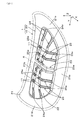
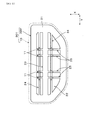
As shown in FIG. 1, the vehicle hood 1 of the first embodiment (hereinafter also simply referred to as “hood 1”) includes an
アウタパネル10は、フード外表面(外側意匠面)を構成している。このアウタパネル10は、「フードアウタ」とも称呼される。インナパネル20は、アウタパネル10の裏面側に重なるように設けられている。このインナパネル20は、「フードインナ」とも称呼される。これらアウタパネル10及びインナパネル20はともに、板材によって構成されている。
The
インナパネル20は、アウタパネル10の外周に沿って環状に延在する外周骨格21を備えている。外周骨格21は、アウタパネル10の裏面に接合されている。この外周骨格21は、その内側領域に開口部22を有する。この場合、外周骨格21は、開口部22の前側を区画する前縁部21aと、開口部22の後側を区画する後縁部21bと、開口部22の左側を区画する左縁部21cと、開口部22の右側を区画する右縁部21dと、に大別される。
The
インナパネル20は、外周骨格21の開口部22に架け渡されるように延在する複数の骨格を備えている。この複数の骨格には、1つの主骨格23と、複数の副骨格24,25と、が含まれている。本実施形態では、主骨格23に対する補助的な副骨格として、複数(図1では2つ)の第1副骨格24と、複数(図1では4つ)の第2副骨格25と、が設けられている。
The
主骨格23は、外周骨格21の前縁部21aと後縁部21bを繋ぐ骨格である。この主骨格23は、その両端部23a,23aがいずれも外周骨格21に連結された状態で開口部22においてアウタパネル10に接合されることなく車両前後方向である第1方向Xを長手方向として長尺状に延在している。この場合、主骨格23は、少なくとも外周骨格21によって両持ち支持される。本実施形態において、この主骨格23は1つのみ設けられ、且つ副骨格24,25よりも剛性が高くなるように構成されている。
The
第1副骨格24は、外周骨格21の左縁部21cと右縁部21dを繋ぐ骨格である。この第1副骨格24は、その両端部24a,24aがいずれも外周骨格21に連結された状態で開口部22において第2方向Yに長尺状に延在している。この第1副骨格24は、1つの主骨格23及び4つの第2副骨格25のそれぞれと交差し、且つその交差部分において交差した骨格に連結されている。この場合、第1副骨格24は、少なくとも外周骨格21によって両持ち支持される。
The
第2副骨格25は、主骨格23と同様に外周骨格21の前縁部21aと後縁部21bを繋ぐ骨格である。この第2副骨格25は、その両端部25a,25aがいずれも外周骨格21に連結された状態で開口部22において第1方向Xに長尺状に延在している。この第2副骨格25は、2つの第1副骨格24のそれぞれと交差し、且つその交差部分において交差した骨格に連結されている。この場合、第2副骨格25は、少なくとも外周骨格21によって両持ち支持される。
Like the
副骨格24,25はいずれも、主骨格23よりも剛性が高くなるように構成されている。本構成を実現するために、例えば骨格幅、骨格厚み、断面係数などの、剛性に関するパラメータについて、副骨格24,25が主骨格23を下回る(相対的に剛性が低くなる)ように構成される。
The
副骨格24,25はいずれも、接合層11を介してアウタパネル10の裏面10aに接合されている。この接合層11は、マスチック接着剤(合成ゴムを主成分とした弾性接着剤)からなるのが好ましい。マスチック接着剤は、車体工程で塗布されて、塗装焼付け炉で硬化する。マスチック接着剤は、フード1全体の剛性を増すとともに、被接着体であるアウタパネル10及びインナパネル20の振動と騒音を低く抑えるのに有効である。
The
以下に、上記の主骨格23及び副骨格24,25の更なる具体的な構造について説明する。
Hereinafter, further specific structures of the
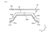
図2に示されるように、主骨格23は、アウタパネル10の裏面10aとの間に隙間12を隔てて延在している。この主骨格23は、傾斜部23b,23cと、水平部23dと、を備えている。傾斜部23bは、外周骨格21の前縁部21aからアウタパネル10に向けて傾斜しつつ延在する部位である。傾斜部23cは、外周骨格21の後縁部21bからアウタパネル10に向けて傾斜しつつ延在する部位である。水平部23dは、傾斜部23bと傾斜部23cとを連結する部位である。この水平部23dは、主骨格23の各部位のうちアウタパネル10の裏面10aに最も近い部位である。
As illustrated in FIG. 2, the
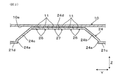
図3に示されるように、第1副骨格24は、傾斜部24b,24cと、水平部24dと、を備えている。傾斜部24bは、外周骨格21の左縁部21cからアウタパネル10に向けて傾斜しつつ延在する部位である。傾斜部24cは、外周骨格21の右縁部21dからアウタパネル10に向けて傾斜しつつ延在する部位である。水平部24dは、傾斜部24bと傾斜部24cとを連結する部位である。この水平部24dは、第1副骨格24の各部位のうちアウタパネル10の裏面10aに最も近い位置であり、且つ主骨格23の水平部23dよりもアウタパネル10の裏面10aに近い位置にある。
As shown in FIG. 3, the
第1副骨格24は、水平部24dに設けられた接合部26,27のそれぞれにおいて、上記の接合層11を介してアウタパネル10の裏面10aに接合されている。即ち、第1副骨格24は、フード厚み方向である第3方向Zについて主骨格23よりもアウタパネル10に近い位置においてアウタパネル10に接合されている。ここで、接合部26は、第1副骨格24と第2副骨格25との連結部分である。このため、接合部26は、第1副骨格24の一部と第2副骨格25の一部とによって構成されている。接合部27は、水平部24dにおいて接合部26よりも主骨格23に近い位置に設けられている。
The
図4に示されるように、第2副骨格25は、傾斜部25b,25cと、水平部25dと、を備えている。傾斜部25bは、外周骨格21の前縁部21aからアウタパネル10に向けて傾斜しつつ延在する部位である。傾斜部25cは、外周骨格21の後縁部21bからアウタパネル10に向けて傾斜しつつ延在する部位である。水平部25dは、傾斜部25bと傾斜部25cとを連結する部位である。この水平部25dは、第2副骨格25の各部位のうちアウタパネル10の裏面10aに最も近い位置であり、且つ主骨格23の水平部23dよりもアウタパネル10の裏面10aに近い位置にある。
As shown in FIG. 4, the
第2副骨格25は、水平部25dに設けられた上記の接合部26において、上記の接合層11を介してアウタパネル10の裏面10aに接合されている。即ち、第2副骨格25は、フード厚み方向である第3方向Zについて主骨格23よりもアウタパネル10に近い位置においてアウタパネル10に接合されている。
The
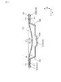
図5及び図6が参照されるように、第1副骨格24は、水平部24dに凹部28を備えている。この凹部28は、アウタパネル10の裏面10aから遠ざかる方向に段差状に凹んだ部位である。そして、第1副骨格24は、この凹部28において主骨格23と交差し且つ主骨格23に連結されている。即ち、インナパネル20は、主骨格23から枝状に延びる第1副骨格24においてアウタパネル10に接合されている。
As shown in FIGS. 5 and 6, the
凹部28は、第1副骨格24の水平部24dの一部であるとともに、主骨格23の水平部23dの一部でもあり、主骨格23とアウタパネル10との間に該アウタパネル10の変形を許容する隙間12(図2参照)を形成するように構成されている。この隙間12(凹部28)は、第3方向Zについてアウタパネル10と主骨格23との間に一定の距離を確保することによって、アウタパネル10と主骨格23との干渉を回避するための干渉回避空間として設けられる。
The
主骨格23は、その水平部23dに長手方向に沿って延びる溝部23eを備えている。この溝部23eは、主骨格23の中央部を段差状に凹ませることによって形成される。これにより、主骨格23自体の剛性を高めることができる。
The
上記の実施形態1によれば、以下のような作用効果が得られる。 According to said Embodiment 1, the following effects are obtained.
上記のフード1において、インナパネル20の主骨格23は、フード1全体の剛性を維持する機能を果たす一方で、アウタパネル10に接合されていないため歩行者(典型的には歩行者の頭部)との衝突初期にアウタパネル10の変形部位から受ける荷重が小さい。このため、歩行者がアウタパネル10に衝突したとき、アウタパネル10の変形が主骨格23によって阻害されにくい。これに対して、副骨格24,25はいずれも、主骨格23よりもアウタパネル10に近い位置においてアウタパネル10に接合されている。このため、主骨格23がアウタパネル10に接合されていなくても、アウタパネル10の張り剛性を副骨格24,25によって維持することができる。従って、フード1を閉めた際などにアウタパネル10に生じる歪を小さく抑えることができる。
In the hood 1 described above, the
また、アウタパネル10は、主骨格23よりも剛性が低い副骨格24,25によって支持されるため、歩行者との衝突時のアウタパネル10の変形が副骨格24,25によって阻害されいくい。このため、歩行者がアウタパネル10から受ける反力を小さく抑えることができる。
Further, since the
その結果、フード剛性を高く維持できるとともに衝突時にアウタパネル10が変形し易いフード1を提供できる。ここでいう「フード剛性」とは、アウタパネル10の張り剛性及びフード1全体での剛性をいう。
As a result, it is possible to provide the hood 1 that can maintain the hood rigidity high and the
更に、インナパネル20の主骨格23及び副骨格24,25のそれぞれが外周骨格21によって両持ち支持される構造であるため、片持ち支持される場合に比べて剛性を高くできる分、各骨格を細くすることができ、また外周骨格21の開口部22の開口面積を広げる(換言すれば、外周骨格21の断面積を小さく抑える)ことができる。その結果、少ない断面の外周骨格21によってアウタパネル10を効率的に支持するとともに、フード1の軽量化を図ることができる。
Further, since each of the
また、外周骨格21の断面積を減らした分を、副骨格24,25によってインナパネル20の全体にバランス良く細分化して配置している。このため、インナパネル20は、アウタパネル10から入力された衝突荷重をパネル全体で受けることがなく、衝突荷重の入力点に対応した位置で受けて局部的に変形し易い。
In addition, the portion of the
また、上記のフード1によれば、インナパネル20において、第1副骨格24が傾斜部24b,24cを備え、第2副骨格25が傾斜部25b,25cを備えるため、歩行者との衝突時にアウタパネル10に対して副骨格24,25が突っ張りにくくなり、副骨格24,25がアウタパネル10から受けた衝突荷重をこれら傾斜部24b,24c,25b,25cによって逃がすことができる。
Moreover, according to said hood 1, in the
また、上記のフード1によれば、該フード1の大きさや形状等に応じて第1副骨格24及び第2副骨格25を適宜に組み合わせることによって、アウタパネル10を適正に支持することが可能になる。
Further, according to the hood 1 described above, the
また、上記のフード1によれば、第1副骨格24が主骨格23に連結されることによって外周骨格21に加えて主骨格23にも支持されるため、アウタパネル10の衝突荷重を第1副骨格24が安定して受けることができる。
Further, according to the hood 1 described above, since the
また、上記のフード1によれば、アウタパネル10に歩行者が衝突したとき、図7に示されるように、このアウタパネル10は、初期位置(二点鎖線で示される位置)から変形位置(実線で示される位置)へと塑性変形する。このとき、アウタパネル10は隙間12によって主骨格23に干渉しにくく、アウタパネル10の塑性変形が主骨格23によって阻害されにくい。これにより、アウタパネル10の変形可能な領域が広がる。また、第1副骨格24の凹部28を利用して隙間12を形成することができ合理的である。
Moreover, according to said hood 1, when a pedestrian collides with the
また、上記のフード1によれば、第1副骨格24が第2副骨格25と交差し且つ第2副骨格25に連結されているため、第1副骨格24及び第2副骨格25が互いに支持し合う関係になり、アウタパネル10の支持に必要な副骨格の数を少なくできる。
Further, according to the hood 1 described above, the
また、上記のフード1によれば、インナパネル20の主骨格23は車両前後方向を長手方向として長尺状に延在しているため、主骨格23が車両左右方向に延在する場合に比べて、主骨格23の長さを短く抑えることができる。
Further, according to the hood 1 described above, the
また、上記のフード1によれば、インナパネル20の主骨格23は、車両左右方向の中央部に1つのみ設けられているため、主骨格23の数を最小限に抑えた上でフード1全体の左右の剛性バランスを整えることができる。
Further, according to the hood 1 described above, only one
上述の実施形態1において、主骨格23及び副骨格24,25の数や配置を、例えば以下の実施形態2〜4のように変更することもできる。
In the above-described first embodiment, the number and arrangement of the
(実施形態2)
図8に示されるように、実施形態2のフード101は、アウタパネル10及びインナパネル120を備えている。インナパネル120は、実施形態1におけるインナパネル20と比べた場合、主骨格23の数及び配置のみが異なる。即ち、このインナパネル120は、2つの主骨格23と、2つの第1副骨格24と、4つの第2副骨格25と、を備えている。2つの主骨格23は、第2方向Yの中央部から若干両側に外れた位置において延在している。その他の構成は、インナパネル20の構成と同様である。
(Embodiment 2)
As shown in FIG. 8, the
実施形態2のフード101によれば、上記のインナパネル20の場合よりも主骨格23の数を増やすことによってフード101全体の剛性を高めることができる。
その他、実施形態1と同様の作用効果を奏する。
According to the
In addition, the same effects as those of the first embodiment are obtained.
(実施形態3)
図9に示されるように、実施形態3のフード201は、アウタパネル10及びインナパネル220を備えている。インナパネル220は、実施形態1におけるインナパネル20と比べた場合、第1副骨格24が省略されている。即ち、このインナパネル220は、1つの主骨格23と、4つの第2副骨格25と、を備え、第1副骨格24のような骨格を備えていない。その他の構成は、インナパネル20の構成と同様である。
(Embodiment 3)
As shown in FIG. 9, the
実施形態3のフード201によれば、アウタパネル10の張り剛性を低下させることが可能な場合に、第1副骨格24を省略してフード201の軽量化を図ることができる。
その他、実施形態1と同様の作用効果を奏する。
According to the
In addition, the same effects as those of the first embodiment are obtained.
(実施形態4)
図10に示されるように、実施形態4のフード301は、アウタパネル10及びインナパネル320を備えている。インナパネル320は、実施形態1におけるインナパネル20と比べた場合、主骨格23の延在方向が異なる。即ち、このインナパネル320は、1つの主骨格23が2つの第1副骨格24の間において第2方向Yに延在するように構成されている。その他の構成は、インナパネル20の構成と同様である。
(Embodiment 4)
As shown in FIG. 10, the
実施形態4のフード301によれば、フード301全体の左右の剛性バランスを高めることができる。
その他、実施形態1と同様の作用効果を奏する。
According to the
In addition, the same effects as those of the first embodiment are obtained.
本発明は、上記の典型的な実施形態のみに限定されるものではなく、本発明の目的を逸脱しない限りにおいて種々の応用や変形が考えられる。例えば、上記の実施形態を応用した次の各形態を実施することもできる。 The present invention is not limited to the above-described exemplary embodiments, and various applications and modifications can be considered without departing from the object of the present invention. For example, the following embodiments applying the above-described embodiment can be implemented.
上記の実施形態1では、第1副骨格24が傾斜部24b,24cを備え、第2副骨格25が傾斜部25b,25cを備える場合について例示したが、必要に応じて傾斜部24b,24c及び傾斜部25b,25cの少なくとも一方を省略することもできる。
In the first embodiment, the case where the
上記の実施形態1では、第1副骨格24が主骨格23と交差し且つ主骨格23に連結される場合について例示したが、第1副骨格24が主骨格23に連結されることなく主骨格23と立体的に交差する構造を採用することもできる。同様に、上記の実施形態1では、第1副骨格24が第2副骨格25と交差し且つ第2副骨格25に連結される場合について例示したが、第1副骨格24が第2副骨格25に連結されることなく第2副骨格25と立体的に交差する構造を採用することもできる。
In the first embodiment, the case where the
上記の実施形態1〜4のように、第1副骨格24及び第2副骨格25の少なくとも一方が、主骨格23よりもアウタパネル10に近い位置においてアウタパネル10に接合されていれば、各骨格の数や配置を必要に応じて種々変更することができる。
If at least one of the
上記の実施形態1〜4のフードの構造を、エンジンフードのみならず、エンジンルーム以外を覆うテールゲート、ドア、トランクリッド等の蓋体の構造に適用することもできる。 The structure of the hood of the first to fourth embodiments can be applied not only to the engine hood but also to the structure of a lid body such as a tailgate, a door, or a trunk lid that covers other than the engine room.
1,101,201,301 車両用フード
10 アウタパネル
11 接合層
12 隙間
20,120,220,320 インナパネル
21 外周骨格
22 開口部
23 主骨格
24 第1副骨格(副骨格)
24b,24c 傾斜部
25 第2副骨格(副骨格)
25b,25c 傾斜部
26,27 接合部
28 凹部
1, 101, 201, 301 Hood for
22
24b, 24c Inclined
25b, 25c Inclined
Claims (9)
上記インナパネルは、
上記アウタパネルの外周に沿って環状に延在し内側領域に開口部を有する外周骨格と、
両端部がいずれも上記外周骨格に連結された状態で上記開口部において上記アウタパネルに接合されることなく延在する主骨格と、
上記主骨格よりも剛性が低く、両端部がいずれも上記外周骨格に連結された状態で上記開口部において延在する副骨格と、
を含み、
上記副骨格は、上記主骨格よりも上記アウタパネルに近い位置において上記アウタパネルに接合されている、車両用フード。 A vehicle hood comprising: an outer panel constituting an outer surface of the hood; and an inner panel provided on the back side of the outer panel,
The inner panel
An outer peripheral skeleton extending annularly along the outer periphery of the outer panel and having an opening in the inner region;
A main skeleton that extends without being joined to the outer panel at the opening in a state where both ends are connected to the outer peripheral skeleton,
A sub-skeleton that is lower in rigidity than the main skeleton and extends at the opening in a state where both ends are connected to the outer peripheral skeleton;
Including
The vehicular hood, wherein the sub skeleton is joined to the outer panel at a position closer to the outer panel than the main skeleton.
Priority Applications (1)
| Application Number | Priority Date | Filing Date | Title |
|---|---|---|---|
| JP2016076407A JP6536456B2 (en) | 2016-04-06 | 2016-04-06 | Vehicle hood |
Applications Claiming Priority (1)
| Application Number | Priority Date | Filing Date | Title |
|---|---|---|---|
| JP2016076407A JP6536456B2 (en) | 2016-04-06 | 2016-04-06 | Vehicle hood |
Publications (2)
| Publication Number | Publication Date |
|---|---|
| JP2017185902A true JP2017185902A (en) | 2017-10-12 |
| JP6536456B2 JP6536456B2 (en) | 2019-07-03 |
Family
ID=60044569
Family Applications (1)
| Application Number | Title | Priority Date | Filing Date |
|---|---|---|---|
| JP2016076407A Active JP6536456B2 (en) | 2016-04-06 | 2016-04-06 | Vehicle hood |
Country Status (1)
| Country | Link |
|---|---|
| JP (1) | JP6536456B2 (en) |
Cited By (2)
| Publication number | Priority date | Publication date | Assignee | Title |
|---|---|---|---|---|
| CN109292005A (en) * | 2018-11-21 | 2019-02-01 | 奇瑞汽车股份有限公司 | Automobile front hatch cover |
| US20220105989A1 (en) * | 2020-10-02 | 2022-04-07 | GM Global Technology Operations LLC | Enclosed volume sandwich hood |
Citations (8)
| Publication number | Priority date | Publication date | Assignee | Title |
|---|---|---|---|---|
| JP2005239092A (en) * | 2004-02-27 | 2005-09-08 | Kanto Auto Works Ltd | Hood structure for automobile |
| JP2006321314A (en) * | 2005-05-18 | 2006-11-30 | Nissan Motor Co Ltd | Automotive engine hood structure |
| JP2007210495A (en) * | 2006-02-10 | 2007-08-23 | Mazda Motor Corp | Automotive engine hood structure |
| JP2007223414A (en) * | 2006-02-22 | 2007-09-06 | Toyota Motor Corp | Vehicle hood structure |
| JP2008110668A (en) * | 2006-10-30 | 2008-05-15 | Kanto Auto Works Ltd | Vehicle hood structure |
| JP2009035088A (en) * | 2007-08-01 | 2009-02-19 | Mazda Motor Corp | Vehicle bonnet structure |
| US20150028624A1 (en) * | 2013-07-25 | 2015-01-29 | GM Global Technology Operations LLC | Vehicle hood assembly |
| JP2015107701A (en) * | 2013-12-04 | 2015-06-11 | スズキ株式会社 | Vehicle hood structure |
-
2016
- 2016-04-06 JP JP2016076407A patent/JP6536456B2/en active Active
Patent Citations (8)
| Publication number | Priority date | Publication date | Assignee | Title |
|---|---|---|---|---|
| JP2005239092A (en) * | 2004-02-27 | 2005-09-08 | Kanto Auto Works Ltd | Hood structure for automobile |
| JP2006321314A (en) * | 2005-05-18 | 2006-11-30 | Nissan Motor Co Ltd | Automotive engine hood structure |
| JP2007210495A (en) * | 2006-02-10 | 2007-08-23 | Mazda Motor Corp | Automotive engine hood structure |
| JP2007223414A (en) * | 2006-02-22 | 2007-09-06 | Toyota Motor Corp | Vehicle hood structure |
| JP2008110668A (en) * | 2006-10-30 | 2008-05-15 | Kanto Auto Works Ltd | Vehicle hood structure |
| JP2009035088A (en) * | 2007-08-01 | 2009-02-19 | Mazda Motor Corp | Vehicle bonnet structure |
| US20150028624A1 (en) * | 2013-07-25 | 2015-01-29 | GM Global Technology Operations LLC | Vehicle hood assembly |
| JP2015107701A (en) * | 2013-12-04 | 2015-06-11 | スズキ株式会社 | Vehicle hood structure |
Cited By (4)
| Publication number | Priority date | Publication date | Assignee | Title |
|---|---|---|---|---|
| CN109292005A (en) * | 2018-11-21 | 2019-02-01 | 奇瑞汽车股份有限公司 | Automobile front hatch cover |
| CN109292005B (en) * | 2018-11-21 | 2021-03-30 | 奇瑞汽车股份有限公司 | car front hatch |
| US20220105989A1 (en) * | 2020-10-02 | 2022-04-07 | GM Global Technology Operations LLC | Enclosed volume sandwich hood |
| US11628888B2 (en) * | 2020-10-02 | 2023-04-18 | GM Global Technology Operations LLC | Enclosed volume sandwich hood |
Also Published As
| Publication number | Publication date |
|---|---|
| JP6536456B2 (en) | 2019-07-03 |
Similar Documents
| Publication | Publication Date | Title |
|---|---|---|
| JP3838125B2 (en) | Fender structure | |
| JP6507816B2 (en) | Vehicle rear structure | |
| JP2020199904A (en) | Vehicle hood | |
| CN113260531B (en) | Trunk lid of vehicle | |
| JP5352741B2 (en) | Body front structure | |
| JP4092484B2 (en) | Vehicle front structure | |
| JP7360627B2 (en) | Vehicle bonnet structure | |
| WO2011162089A1 (en) | Structure of front section of vehicle body | |
| JP2019098988A (en) | Floor panel structure | |
| JP2019038301A (en) | Body structure | |
| JP6536456B2 (en) | Vehicle hood | |
| JP2015089788A (en) | Front body structure | |
| JP2020147255A (en) | Vehicle rear structure | |
| JP5618329B2 (en) | Vehicle body superstructure | |
| JP6320121B2 (en) | Anti-vibration structure for automotive back panel | |
| JP7081393B2 (en) | Front structure of the passenger compartment | |
| JP5741420B2 (en) | Vehicle back door structure | |
| JP6094364B2 (en) | Body front structure | |
| JP6237670B2 (en) | Upper body structure of the vehicle | |
| JP5251368B2 (en) | Body superstructure | |
| JP6508575B2 (en) | Vehicle roof structure | |
| JP6981187B2 (en) | Body structure | |
| JP6048184B2 (en) | Front body structure of the vehicle | |
| JP6576419B2 (en) | Body superstructure | |
| JP2019055677A (en) | Vehicle back door inner panel |
Legal Events
| Date | Code | Title | Description |
|---|---|---|---|
| A621 | Written request for application examination |
Free format text: JAPANESE INTERMEDIATE CODE: A621 Effective date: 20180625 |
|
| A977 | Report on retrieval |
Free format text: JAPANESE INTERMEDIATE CODE: A971007 Effective date: 20190405 |
|
| TRDD | Decision of grant or rejection written | ||
| A01 | Written decision to grant a patent or to grant a registration (utility model) |
Free format text: JAPANESE INTERMEDIATE CODE: A01 Effective date: 20190507 |
|
| A61 | First payment of annual fees (during grant procedure) |
Free format text: JAPANESE INTERMEDIATE CODE: A61 Effective date: 20190520 |
|
| R150 | Certificate of patent or registration of utility model |
Ref document number: 6536456 Country of ref document: JP Free format text: JAPANESE INTERMEDIATE CODE: R150 |
|
| R250 | Receipt of annual fees |
Free format text: JAPANESE INTERMEDIATE CODE: R250 |
|
| R250 | Receipt of annual fees |
Free format text: JAPANESE INTERMEDIATE CODE: R250 |
|
| R250 | Receipt of annual fees |
Free format text: JAPANESE INTERMEDIATE CODE: R250 |
|
| R250 | Receipt of annual fees |
Free format text: JAPANESE INTERMEDIATE CODE: R250 |
|
| R250 | Receipt of annual fees |
Free format text: JAPANESE INTERMEDIATE CODE: R250 |