JP2017187624A - projector - Google Patents
projector Download PDFInfo
- Publication number
- JP2017187624A JP2017187624A JP2016076371A JP2016076371A JP2017187624A JP 2017187624 A JP2017187624 A JP 2017187624A JP 2016076371 A JP2016076371 A JP 2016076371A JP 2016076371 A JP2016076371 A JP 2016076371A JP 2017187624 A JP2017187624 A JP 2017187624A
- Authority
- JP
- Japan
- Prior art keywords
- wind direction
- unit
- liquid crystal
- crystal panel
- light
- Prior art date
- Legal status (The legal status is an assumption and is not a legal conclusion. Google has not performed a legal analysis and makes no representation as to the accuracy of the status listed.)
- Pending
Links
- 230000003287 optical effect Effects 0.000 claims abstract description 103
- 239000004973 liquid crystal related substance Substances 0.000 claims abstract description 97
- 238000000926 separation method Methods 0.000 claims description 27
- 230000008859 change Effects 0.000 abstract description 6
- 238000010586 diagram Methods 0.000 description 11
- 238000001816 cooling Methods 0.000 description 9
- 238000000034 method Methods 0.000 description 8
- 230000006870 function Effects 0.000 description 5
- 229910052751 metal Inorganic materials 0.000 description 5
- 239000002184 metal Substances 0.000 description 5
- 238000001514 detection method Methods 0.000 description 4
- 238000005286 illumination Methods 0.000 description 4
- 238000003780 insertion Methods 0.000 description 4
- 230000037431 insertion Effects 0.000 description 4
- 238000005452 bending Methods 0.000 description 3
- 238000006243 chemical reaction Methods 0.000 description 3
- 230000007423 decrease Effects 0.000 description 3
- 239000011521 glass Substances 0.000 description 3
- 230000010287 polarization Effects 0.000 description 3
- 239000000853 adhesive Substances 0.000 description 2
- 230000001070 adhesive effect Effects 0.000 description 2
- 238000013459 approach Methods 0.000 description 2
- 239000011159 matrix material Substances 0.000 description 2
- 230000004043 responsiveness Effects 0.000 description 2
- 230000008901 benefit Effects 0.000 description 1
- 230000006866 deterioration Effects 0.000 description 1
- 230000000694 effects Effects 0.000 description 1
- 230000006872 improvement Effects 0.000 description 1
- 239000000463 material Substances 0.000 description 1
- 230000007246 mechanism Effects 0.000 description 1
- QSHDDOUJBYECFT-UHFFFAOYSA-N mercury Chemical compound [Hg] QSHDDOUJBYECFT-UHFFFAOYSA-N 0.000 description 1
- 229910052753 mercury Inorganic materials 0.000 description 1
- 229910001507 metal halide Inorganic materials 0.000 description 1
- 150000005309 metal halides Chemical class 0.000 description 1
- 230000004048 modification Effects 0.000 description 1
- 238000012986 modification Methods 0.000 description 1
- 230000008569 process Effects 0.000 description 1
- 238000012545 processing Methods 0.000 description 1
- 230000005855 radiation Effects 0.000 description 1
- 230000001105 regulatory effect Effects 0.000 description 1
- 239000000758 substrate Substances 0.000 description 1
- 230000002194 synthesizing effect Effects 0.000 description 1
Images






Landscapes
- Liquid Crystal (AREA)
- Mounting And Adjusting Of Optical Elements (AREA)
- Projection Apparatus (AREA)
- Transforming Electric Information Into Light Information (AREA)
Abstract
Description
本発明は、プロジェクターに関する。 The present invention relates to a projector.
従来、光源から射出された光を画像情報に応じて変調し、変調した光をスクリーン等の投写面に投写するプロジェクターが知られている。このプロジェクターには、液晶パネル等の光変調装置や、光変調装置の前後に配置される入射側偏光板や射出側偏光板等の光学部品が備えられている。
ところで、近年、投写される画像のコントラスト特性等を向上させるために、光変調装置の光入射側や光射出側に補償素子等の光学素子を配置した構成が用いられるようになってきている。この構成においては、光変調装置に対して光学素子が正しい位置に配置されていないと、所望の特性を得ることができないため、光変調装置に対して光学素子の位置を調整可能とする技術が提案されている(例えば、特許文献1参照)。
また、近年、より明るい画像の投写が可能なプロジェクターが望まれており、光源からの光で発熱する光変調装置を効率的に冷却する技術が提案されている(例えば、特許文献2参照)。
Conventionally, a projector that modulates light emitted from a light source in accordance with image information and projects the modulated light onto a projection surface such as a screen is known. This projector includes a light modulation device such as a liquid crystal panel, and optical components such as an incident side polarizing plate and an emission side polarizing plate arranged before and after the light modulation device.
Incidentally, in recent years, in order to improve the contrast characteristics and the like of a projected image, a configuration in which an optical element such as a compensation element is arranged on the light incident side or the light emission side of a light modulation device has been used. In this configuration, since a desired characteristic cannot be obtained unless the optical element is arranged at a correct position with respect to the light modulation device, there is a technique that makes it possible to adjust the position of the optical element with respect to the light modulation device. It has been proposed (see, for example, Patent Document 1).
In recent years, a projector capable of projecting a brighter image has been desired, and a technique for efficiently cooling a light modulation device that generates heat by light from a light source has been proposed (for example, see Patent Document 2).
特許文献1に記載のプロジェクターは、光変調装置と、光変調装置を介した光の位相差を補償する光学補償素子と、光学補償素子が取り付けられ、光学補償素子の位置を調整する調整部材と、調整部材を支持する支持部材とを備える。調整部材は、互いに離間する方向に突出する一対の腕部を有する。そして、調整部材は、一対の腕部の先端が支持部材に係合し、回転可能に支持部材に支持されるように構成されている。そして、光学補償素子は、支持部材に対して調整部材が回転されることで姿勢(位置)が調整される。
特許文献2には、3枚の液晶パネルの透過光を合成するための合成プリズムを有する液晶プロジェクターに用いられる液晶パネル冷却装置が記載されている。
この液晶パネル冷却装置は、液晶パネル(光変調装置)の光の出射側表示面および合成プリズムの光入射面との間を、ファンの回転により生じる風を通し、合成プリズムの光の入射面側に、液晶パネル出射側表示面方向に風向きを変えるための風向板を備えている。
The projector described in Patent Document 1 includes an optical modulation device, an optical compensation element that compensates for a phase difference of light that passes through the optical modulation device, an adjustment member that is attached with the optical compensation element and adjusts the position of the optical compensation element, And a support member that supports the adjustment member. The adjustment member has a pair of arms that protrude in directions away from each other. And the adjustment member is comprised so that the front-end | tip of a pair of arm part may engage with a support member, and it is supported by the support member rotatably. The posture (position) of the optical compensation element is adjusted by rotating the adjustment member with respect to the support member.
This liquid crystal panel cooling device passes the air generated by the rotation of the fan between the light emission side display surface of the liquid crystal panel (light modulation device) and the light incident surface of the synthetic prism, and the light incident surface side of the synthetic prism In addition, a wind direction plate for changing the wind direction toward the liquid crystal panel emission side display surface is provided.
特許文献1には光変調装置の冷却方法については記載されていないが、特許文献2に記載の技術を用いて光変調装置を冷却する構成が考えられる。しかしながら、この技術では、光変調装置を充分冷却できない場合がある。すなわち、特許文献1に記載の技術は、光学補償素子の姿勢によっては、光変調装置と光学補償素子との隙間が狭くなる場合があるため、特許文献2に記載の風向板を備える構成であっても、光変調装置と光学補償素子との間に流通する冷却空気の風量が不十分で、光変調装置が許容の温度を超える恐れがある。
Patent Document 1 does not describe a method for cooling the light modulation device, but a configuration in which the light modulation device is cooled using the technique described in
本発明は、上述の課題の少なくとも一部を解決するためになされたものであり、以下の形態または適用例として実現することが可能である。 SUMMARY An advantage of some aspects of the invention is to solve at least a part of the problems described above, and the invention can be implemented as the following forms or application examples.
[適用例1]本適用例に係るプロジェクターは、光源と、前記光源から射出された光を画像情報に応じて変調する光変調装置と、前記光変調装置を保持する保持部と、前記光変調装置に対向して配置され、入射する光を光学的に変換する光学素子と、前記光学素子を保持する素子保持体と、前記光変調装置と前記光学素子との間に流通する空気の風量を調整する風向調整部と、を備え、前記素子保持体は、前記光変調装置の光軸に対する前記光学素子の傾きを調整可能に前記保持部に支持され、前記風向調整部は、一端が前記素子保持体に回動可能に支持され、前記光学素子に向かう空気の流れを変える風向変更部を備えることを特徴とする。 Application Example 1 A projector according to this application example includes a light source, a light modulation device that modulates light emitted from the light source according to image information, a holding unit that holds the light modulation device, and the light modulation. An optical element that is disposed opposite to the apparatus and optically converts incident light, an element holder that holds the optical element, and an air volume that flows between the light modulator and the optical element. A wind direction adjusting unit for adjusting, and the element holding body is supported by the holding unit so as to be capable of adjusting an inclination of the optical element with respect to an optical axis of the light modulation device, and one end of the wind direction adjusting unit is the element. A wind direction changing unit is provided that is rotatably supported by the holding body and changes a flow of air toward the optical element.
この構成によれば、プロジェクターは、光変調装置に対向して配置された光学素子の傾きを調整できるので、画質を高めた画像の投写が可能となる。また、プロジェクターは、上述した風向調整部を備えているので、ファンから送風され、光学素子に向かう空気の流れを変え、光変調装置と光学素子との間に流通する空気の風量を調整することができる。よって、光学素子の傾き調整に伴って変わる光変調装置と光学素子との離間距離に対応して双方の部材間に空気を流通させ、光変調装置および光学素子を適切に冷却することが可能となる。
したがって、長期に亘って高画質の画像を投写するプロジェクターの提供が可能となる。
According to this configuration, since the projector can adjust the inclination of the optical element disposed facing the light modulation device, it is possible to project an image with improved image quality. In addition, since the projector includes the wind direction adjusting unit described above, the flow of air that is blown from the fan and directed toward the optical element is changed, and the amount of air flowing between the light modulation device and the optical element is adjusted. Can do. Accordingly, it is possible to appropriately cool the light modulation device and the optical element by allowing air to flow between both members in accordance with the separation distance between the light modulation device and the optical element that changes in accordance with the tilt adjustment of the optical element. Become.
Therefore, it is possible to provide a projector that projects high-quality images over a long period of time.
[適用例2]上記適用例に係るプロジェクターにおいて、前記風向変更部は、前記一端に前記素子保持体に回動可能に支持される軸支部を有し、前記風向調整部は、前記風向変更部の前記軸支部とは離れた位置に接続された移動部を備え、前記移動部は、前記軸支部の回転中心軸に交差する方向に移動可能であることが好ましい。 Application Example 2 In the projector according to the application example described above, the wind direction changing unit has a shaft support part rotatably supported by the element holding body at the one end, and the wind direction adjusting unit is the wind direction changing unit. It is preferable that a moving part connected to a position away from the shaft support part is provided, and the moving part is movable in a direction intersecting the rotation center axis of the shaft support part.
この構成によれば、移動部を移動させることで風向変更部を回動させることができる。よって、光変調装置と光学素子との間に流通させる空気の風量を容易に調整することが可能となる。 According to this configuration, the wind direction changing unit can be rotated by moving the moving unit. Therefore, it is possible to easily adjust the air volume of the air flowing between the light modulation device and the optical element.
[適用例3]上記適用例に係るプロジェクターにおいて、前記素子保持体は、前記光学素子が取り付けられる取付部、および前記取付部から前記光軸に交差する方向に延出し、前記傾きを調整するために操作される第1操作部を有し、前記移動部は、前記風向変更部に接続され、前記光軸に交差する方向に延出する延出部、および前記延出部の前記風向変更部に接続された部位とは反対側となる端部側に設けられ、移動のために操作される第2操作部を有し、前記第1操作部および前記第2操作部は、前記光学素子に対し、同じ側に配置されていることが好ましい。 Application Example 3 In the projector according to the application example described above, the element holding body is attached to the optical element, and extends from the attachment part in a direction intersecting the optical axis to adjust the inclination. A first operation unit that is operated by the extension unit, the moving unit being connected to the wind direction changing unit and extending in a direction intersecting the optical axis, and the wind direction changing unit of the extending unit A second operation unit that is provided on an end side opposite to the part connected to the optical system and is operated for movement, wherein the first operation unit and the second operation unit are provided on the optical element. On the other hand, they are preferably arranged on the same side.
この構成によれば、第1操作部および第2操作部が光学素子に対して同じ側に配置されている。これによって、作業者は、光学素子の傾き調整、および風向調整部による空気の風量調整を、光学素子の同一側から行うことができるので、2つの調整作業を効率的に行うことが可能となる。
また、光学素子に対して第1操作部および第2操作部が配置されていない側に部材を配置できるので、光学素子の傾き調整を可能に素子保持体が保持部に支持される構造等をスペース効率よく構成することが可能となる。
According to this configuration, the first operation unit and the second operation unit are arranged on the same side with respect to the optical element. Thereby, since the operator can perform the inclination adjustment of the optical element and the air volume adjustment by the wind direction adjusting unit from the same side of the optical element, the two adjustment operations can be efficiently performed. .
In addition, since the member can be arranged on the side where the first operation unit and the second operation unit are not arranged with respect to the optical element, the structure in which the element holding body is supported by the holding unit so that the inclination of the optical element can be adjusted. It is possible to configure the space efficiently.
[適用例4]上記適用例に係るプロジェクターにおいて、前記風向調整部は、前記風向変更部が所定の姿勢で配置される所定の状態を有し、前記風向変更部は、前記一端とは反対側となる他端と前記光変調装置との離間距離が前記所定の状態における前記離間距離より大きくなる回動が可能であることが好ましい。 Application Example 4 In the projector according to the application example, the wind direction adjusting unit has a predetermined state in which the wind direction changing unit is arranged in a predetermined posture, and the wind direction changing unit is opposite to the one end. It is preferable that the separation distance between the other end and the light modulation device can be turned so as to be larger than the separation distance in the predetermined state.
この構成によれば、光学素子の傾き調整によって光変調装置と光学素子との距離が小さくなる場合に、風向変更部の他端と光変調装置との離間距離が大きくなるように風向変更部を回動させることができる。これによって、光変調装置と光学素子との間に適切に空気を流通させ、光変調装置および光学素子を効率よく冷却することができる。 According to this configuration, when the distance between the light modulation device and the optical element is reduced by adjusting the tilt of the optical element, the wind direction changing unit is set so that the separation distance between the other end of the wind direction changing unit and the light modulation device is increased. It can be rotated. Thereby, air can be appropriately circulated between the light modulation device and the optical element, and the light modulation device and the optical element can be efficiently cooled.
[適用例5]上記適用例に係るプロジェクターにおいて、前記風向変更部は、前記離間距離が前記所定の状態における前記離間距離より小さくなる回動が可能であることが好ましい。 Application Example 5 In the projector according to the application example described above, it is preferable that the wind direction changing unit can rotate such that the separation distance is smaller than the separation distance in the predetermined state.
この構成によれば、光学素子の傾き調整によって光変調装置と光学素子との距離が大きくなる場合に、風向変更部の他端と光変調装置との離間距離が小さくなるように風向変更部を回動させることができる。これによって、光変調装置と光学素子との間に流通させる空気の風量を制限することができるので、光変調装置の過冷却を抑制することが可能となる。 According to this configuration, when the distance between the light modulation device and the optical element is increased by adjusting the tilt of the optical element, the wind direction changing unit is set so that the separation distance between the other end of the wind direction changing unit and the light modulation device is reduced. It can be rotated. As a result, the amount of air flowing between the light modulation device and the optical element can be restricted, so that overcooling of the light modulation device can be suppressed.
[適用例6]上記適用例に係るプロジェクターにおいて、前記光変調装置は、液晶パネルであり、前記光学素子は、前記液晶パネルの光射出側に配置され、前記液晶パネルから射出された光の位相差を補償する補償素子であり、前記傾きの調整は、前記補償素子の対角方向に延出する対角軸を中心とする回転方向の調整により行われることが好ましい。 Application Example 6 In the projector according to the application example described above, the light modulation device is a liquid crystal panel, and the optical element is disposed on a light emission side of the liquid crystal panel, and a level of light emitted from the liquid crystal panel. It is a compensation element that compensates for a phase difference, and the adjustment of the tilt is preferably performed by adjusting a rotation direction about a diagonal axis extending in a diagonal direction of the compensation element.
この構成によれば、液晶パネルのプレチルト角(ラビング方向)に対応させて、補償素子の傾きを調整できるので、投写される画像のコントラスト比や視野角特性を向上させることができる。よって、長期に亘って高画質の画像を投写するプロジェクターの提供が可能となる。 According to this configuration, since the tilt of the compensation element can be adjusted in accordance with the pretilt angle (rubbing direction) of the liquid crystal panel, the contrast ratio and viewing angle characteristics of the projected image can be improved. Therefore, it is possible to provide a projector that projects high-quality images over a long period of time.
以下、本実施形態に係るプロジェクターについて、図面を参照して説明する。
本実施形態のプロジェクターは、光源から射出された光を画像情報に応じて変調してスクリーン等の投写面に拡大投写する。
〔プロジェクターの主な構成〕
図1は、本実施形態のプロジェクター1の概略構成を示す模式図である。
プロジェクター1は、図1に示すように、外装を構成する外装筐体2、制御部(図示省略)、光源装置31を有する光学ユニット3、および冷却装置4を備える。なお、図示は省略するが、外装筐体2の内部には、さらに、光源装置31や制御部に電力を供給する電源装置等が配置されている。
Hereinafter, the projector according to the present embodiment will be described with reference to the drawings.
The projector according to the present embodiment modulates light emitted from a light source according to image information and enlarges and projects the light onto a projection surface such as a screen.
[Main components of the projector]
FIG. 1 is a schematic diagram illustrating a schematic configuration of a projector 1 according to the present embodiment.
As shown in FIG. 1, the projector 1 includes an
外装筐体2は、詳細な説明は省略するが、複数の部材で構成されている。そして、外装筐体2には、外気を取り込むための吸気口、および外装筐体2内部の温まった空気を外部に排気する排気口等が設けられている。
Although the detailed description is omitted, the
制御部は、CPU(Central Processing Unit)やROM(Read Only Memory)、RAM(Random Access Memory)等を備え、コンピューターとして機能するものであり、プロジェクター1の動作の制御、例えば、画像の投写に関わる制御等を行う。 The control unit includes a CPU (Central Processing Unit), a ROM (Read Only Memory), a RAM (Random Access Memory), and the like, and functions as a computer, and is related to control of the operation of the projector 1, for example, image projection. Control and so on.
光学ユニット3は、制御部による制御の下、光源装置31から射出された光を光学的に処理して投写する。
光学ユニット3は、図1に示すように、光源装置31に加え、インテグレーター照明光学系32、色分離光学系33、リレー光学系34、光学装置5、投写レンズ35、およびこれらの部材を光路上の所定位置に配置する光学部品用筐体36やヘッド体37を備える。
The optical unit 3 optically processes and projects the light emitted from the
As shown in FIG. 1, in addition to the
光源装置31は、超高圧水銀ランプやメタルハライドランプ等からなる放電型の光源311およびリフレクター312等を備え、光源311から射出された光をリフレクター312にて反射し、インテグレーター照明光学系32に向けて射出する。
The
インテグレーター照明光学系32は、第1レンズアレイ321、第2レンズアレイ322、偏光変換素子323、および重畳レンズ324を備える。第1レンズアレイ321は、小レンズがマトリックス状に配列された構成を有しており、光源装置31から射出された光を複数の部分光に分割する。第2レンズアレイ322は、第1レンズアレイ321と略同様の構成を有しており、重畳レンズ324とともに、部分光を後述する液晶パネル52の表面に略重畳させる。偏光変換素子323は、第2レンズアレイ322から射出されたランダム光を液晶パネル52で利用可能な略1種類の偏光光に揃える機能を有している。
The integrator illumination
色分離光学系33は、2枚のダイクロイックミラー331,332、および反射ミラー333を備え、インテグレーター照明光学系32から射出された光を赤色光(以下「R光」という)、緑色光(以下「G光」という)、青色光(以下「B光」という)の3色の色光に分離する。
The color separation
リレー光学系34は、入射側レンズ341、リレーレンズ343、および反射ミラー342,344を備え、色分離光学系33で分離されたR光をR光用の液晶パネル52まで導く機能を有する。なお、光学ユニット3は、リレー光学系34がR光を導く構成としているが、これに限らず、例えば、B光を導く構成としてもよい。
The relay
光学装置5は、各色光用に設けられた電気光学装置50(R光用の電気光学装置を50R、G光用の電気光学装置を50G、B光用の電気光学装置を50Bとする)、および色合成光学装置としてのクロスダイクロイックプリズム55を備える。
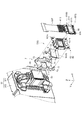
図2は、ヘッド体37および光学装置5を示す斜視図である。図3は、クロスダイクロイックプリズム55および電気光学装置50Gの分解斜視図である。
各電気光学装置50は、図1、図3に示すように、入射側偏光板51、光変調装置としての液晶パネル52、補償素子53、射出側偏光板54、保持部6、支持部7、素子保持体8、および風向調整部9を備える。
The
FIG. 2 is a perspective view showing the
As shown in FIGS. 1 and 3, each electro-
入射側偏光板51は、色分離光学系33で分離された色光のうち、偏光変換素子323で揃えられた偏光光を透過し、その偏光光と異なる偏光光を吸収して液晶パネル52に射出する。入射側偏光板51は、ガラス板に貼り付けられて光学部品用筐体36に配置される。
The incident-side
液晶パネル52は、一対の透明なガラス基板に電気光学物質である液晶が密閉封入された構成を有し、図示しない微小画素がマトリックス状に形成された矩形状の画素領域が形成されている。そして、液晶パネル52の端部には、フレキシブルプリント基板52F(図3参照)が接続されている。
The
液晶パネル52は、フレキシブルプリント基板52Fを介して制御部から入力された駆動信号に応じて液晶の配向状態が制御され、画素領域内に表示画像を形成する。そして、液晶パネル52は、入射側偏光板51から射出された色光を画像情報に応じて変調する。
液晶パネル52は、保持部6に保持される。
In the
The
補償素子53は、液晶パネル52の光射出側に配置される。補償素子53は、液晶パネル52に対向して配置され、入射する光を光学的に変換する光学素子に相当する。補償素子53は、液晶パネル52から射出された光の位相差を補償(液晶パネル52にて正確に変調できなかった位相変調量を微調整)し、投写される画像のコントラスト比や視野角特性の向上に寄与する。補償素子53は、素子保持体8に保持され、液晶パネル52の光軸に対して傾いて配置されている。また、後で詳細に説明するが、補償素子53は、液晶パネル52の光軸に対する傾きが調整可能に構成されている。
The
射出側偏光板54は、補償素子53から射出された光のうち一定方向の偏光光を透過し、その偏光光と異なる偏光光を吸収してクロスダイクロイックプリズム55に射出する。射出側偏光板54は、平面視矩形状に形成され、ガラス板を介してクロスダイクロイックプリズム55に接着固定される。
The exit-side
支持部7は、クロスダイクロイックプリズム55に固定された射出側偏光板54に接着固定され、液晶パネル52が保持された保持部6を支持する。
風向調整部9は、図3に示すように、素子保持体8に支持される風向変更部91を備え、冷却装置4の後述するファン411から送風され、液晶パネル52と補償素子53との間に流通する空気の風量を調整する。なお、図3に示す風向調整部9は、風向変更部91を模式的に示したものである。保持部6、支持部7、素子保持体8および風向調整部9については、後で詳細に説明する。
The
As shown in FIG. 3, the wind
クロスダイクロイックプリズム55は、4つの直角プリズムを貼り合わせた平面視略正方形状をなし、3つの光入射側端面、1つの光射出側端面を有している。各光入射側端面には、各色光用の電気光学装置50が対向して配置される。ここで、図1に示すように、R光用の液晶パネル52の光軸を52Rj、G光用の液晶パネル52の光軸を52Gj、およびB光用の液晶パネル52の光軸を52Bjとする。
The cross
そして、クロスダイクロイックプリズム55は、直角プリズム同士を貼り合わせた界面に誘電体多層膜が形成され、各色光用の電気光学装置50から射出された各色光を合成する。具体的に、クロスダイクロイックプリズム55は、電気光学装置50R,50Bにて変調された色光を反射し、電気光学装置50Gにて変調された色光を透過して、各色光を合成する。
In the cross
投写レンズ35は、複数のレンズ(図示省略)を有し、クロスダイクロイックプリズム55にて合成された光をスクリーン上に拡大投写する。
The
ヘッド体37は、図3に示すように、プリズム支持体371およびヘッド本体372を備える。
プリズム支持体371は、クロスダイクロイックプリズム55の上面に接着固定され、クロスダイクロイックプリズム55を支持する。
ヘッド本体372は、プリズム支持体371および投写レンズ35が固定され、光学部品用筐体36に取り付けられる。
As shown in FIG. 3, the
The
The head
冷却装置4は、詳細な説明は省略するが、吸気装置41、排気装置、および光源装置31等に冷却空気を送風する送風ファン等を備える。吸気装置41は、図1に示すように、ファン411やダクト部材412等を備え、外装筐体2の吸気口から外部の空気を取り込み、取り込んだ空気を光学装置5に送風する。排気装置は、排気ファンやダクト部材等を備え、外装筐体2内部の温まった空気を排気口から排出させる。
Although a detailed description is omitted, the
〔保持部、支持部、素子保持体、および風向調整部の構成〕
ここで保持部6、支持部7、素子保持体8および風向調整部9の具体的な構成について説明する。ここでは、G光用の保持部6、支持部7、素子保持体8および風向調整部9に注目して説明する。なお、以下では、説明の便宜上、図3に示すように、光軸52Gjに沿う方向をY方向、Y方向に直交する上下方向をZ方向、Y方向およびZ方向に直交する方向をX方向(左右方向)とする。また、Y方向において、クロスダイクロイックプリズム55に向かう側を+Y側、図3の図面視において、Z方向における上側を+Z側、X方向における右側を+X側として記載する。
[Configuration of holding part, supporting part, element holding body, and wind direction adjusting part]
Here, specific configurations of the holding
先ず、保持部6について説明する。
保持部6は、図3に示すように、液晶パネル52を収納するフレーム61、およびフレーム61が固定される固定板62を備える。
フレーム61は、金属製であり、液晶パネル52を収納する枠部611、および放熱部612を有している。また、図示は省略するが、フレーム61には、液晶パネル52の温度を検出する温度センサーTE(図示せず)が配置されている。温度センサーTEは、制御部に接続されている。制御部は、温度センサーTEからの検出結果に基づいて、各種ファンの駆動等の制御を行う。
First, the holding
As shown in FIG. 3, the holding
The
枠部611は、図3に示すように、平面視矩形状に形成され、中央部には、入射側偏光板51(図1参照)を透過した色光が入射する開口部6111が形成されている。そして、枠部611には、開口部6111の周囲に、Y方向に貫通する複数の貫通孔61hが設けられている。
放熱部612は、枠部611の上端から突出して平面視矩形状に形成されている。フレキシブルプリント基板52Fの基端側は、この放熱部612に沿うように配置される。
As shown in FIG. 3, the
The
固定板62は、フレーム61のクロスダイクロイックプリズム55側に配置され、液晶パネル52が収納されたフレーム61が固定される。
図4は、クロスダイクロイックプリズム55側から見た電気光学装置50Gの分解斜視図であり、保持部6および素子保持体8を示す図である。
固定板62は、板金からプレス加工等により形成されており、図4に示すように、平面視矩形状に形成されたベース部621、ベース部621の左右両側から屈曲された一対の第1屈曲部622L,622R、およびベース部621の上側から屈曲された一対の第2屈曲部623を有している。
The fixing
FIG. 4 is an exploded perspective view of the electro-
The fixed
ベース部621には、液晶パネル52を透過した色光が通過する矩形状の開口部621aが設けられ、開口部621aの周囲には、貫通孔61hに対応するネジ穴621b(図3参照)が形成されている。また、ベース部621の四隅には、挿通孔621cが形成されている。液晶パネル52が収納されたフレーム61は、貫通孔61hから挿通されたネジがネジ穴621bに挿通されてベース部621に固定される。
The
第1屈曲部622Lは、ベース部621の左側(−X側)に設けられ、第1屈曲部622Rは、ベース部621の右側(+X側)に設けられている。一対の第1屈曲部622L,622Rは、ベース部621からクロスダイクロイックプリズム55側に略90°屈曲されており、互いが左右対称となるように形成されており、素子保持体8を回転可能に支持する機能を有している。また、一対の第1屈曲部622L,622Rは、ベース部621の剛性を高める機能も有している。
The first
そして、各第1屈曲部622L,622Rの上端部には、互いに隣接する方向に屈曲された凸部622La,622Raが設けられている。そして、凸部622La,622Raには、スリット622Ls,622Rsが形成されている。また、各第1屈曲部622L,622Rの下端部には、互いに隣接する方向に屈曲された凸部622Lb,622Rbが設けられている。そして、凸部622Lb,622Rbには、丸孔622Lh,622Rhが形成されている。
And convex part 622La, 622Ra bent in the mutually adjacent direction is provided in the upper end part of each 1st bending
一対の第2屈曲部623は、ベース部621からクロスダイクロイックプリズム55側に略90°屈曲されており、左右方向において、ベース部621の中央で、互いに所定の距離隔てて形成されている。
The pair of second
次に、支持部7について説明する。
支持部7は、前述したように、液晶パネル52が保持された保持部6を支持する。支持部7は、板金からプレス加工等により形成されており、図3に示すように、平面視矩形状のベース部71、ベース部71から保持部6側に屈曲されたパネル支持部72、押圧部73を有している。
ベース部71には、補償素子53を透過した光が通過する矩形状の開口部711が形成されている。
Next, the
As described above, the
The
パネル支持部72は、ベース部71の左右両側でベース部71の四隅近傍から屈曲されており、先端部がベース部621の四隅に設けられた挿通孔621cに遊嵌状態で挿通されるように形成されている。
押圧部73は、ベース部71の左右両側に一対設けられ、それぞれがパネル支持部72の間に設けられている。押圧部73の先端には、V字状の切欠きが設けられている。
The
A pair of
支持部7は、押圧部73が治具等で押圧され、ベース部71が射出側偏光板54に接着固定される。
液晶パネル52を保持する保持部6は、挿通孔621cにパネル支持部72の先端部が遊嵌状態で挿通された状態で位置の調整が行われた後、挿通孔621cとパネル支持部72との間に接着剤が充填されて支持部7に固定される(図2参照)。
In the
The holding
次に、素子保持体8について説明する。
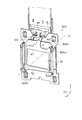
図5は、電気光学装置50Gにおける固定板62および素子保持体8をクロスダイクロイックプリズム55側から見た斜視図である。図6は、素子保持体8および風向調整部9を模式的に示す平面図である。
素子保持体8は、図5に示すように、補償素子53を保持し、固定板62に回動可能に支持される。素子保持体8は、板金からプレス加工等により形成されており、図4に示すように、補償素子53が取り付けられる取付部81、取付部81から突出する腕部82,83、および第1操作部84を有している。
Next, the
FIG. 5 is a perspective view of the fixing
As shown in FIG. 5, the
取付部81は、平面サイズが補償素子53より大きい矩形状に形成されている。補償素子53は、取付部81の−Y側の面に接着固定される。取付部81の中央には、補償素子53を透過した光が通過する開口部811が設けられている。
また、取付部81の下端部には、図6に示すように、左右方向において所定の距離隔てて形成された一対の軸受部812が設けられている。一対の軸受部812は、曲げ加工により、断面の内面が円形となるように形成されている。
The
In addition, as shown in FIG. 6, a pair of bearing
腕部82,83は、取付部81の対向する角部から互いに離間する方向、すなわち、矩形状の補償素子53における対角方向に沿って延出している。具体的に、図4、図5に示すように、腕部82は、補償素子53の右下(+X側および−Z側)の角部近傍から延出している。腕部83は、補償素子53の左上(−X側および+Z側)の角部近傍から延出している。
The
腕部82は、図4に示すように、取付部81に倣って延出した後、+Y側(クロスダイクロイックプリズム55側)に屈曲され、さらに取付部81と略平行に屈曲され、断面がクランク状に形成されている。そして、取付部81と略平行に屈曲された部位の先端部821は、固定板62の丸孔622Rhに挿入されるように形成されている(図4、図5参照)。
腕部83は、取付部81に倣って延出した後、+Y側(クロスダイクロイックプリズム55側)に屈曲され、さらに取付部81と略平行に屈曲され、断面がクランク状に形成されている。そして、取付部81と略平行に屈曲された先端部831は、固定板62のスリット622Lsに挿入されるように形成されている(図4、図5参照)。
As shown in FIG. 4, the
The
そして、素子保持体8は、図5に示すように、腕部82,83の先端部821,831が固定板62に支持され、補償素子53における対角方向に沿う対角軸7Jを中心とする回転方向の調整が可能に構成されている。すなわち、素子保持体8は、光軸52Gjに対する補償素子53の傾きを調整可能に保持部6に支持されている。換言すると、素子保持体8は、光軸52Gjに対する補償素子53の法線53Vの角度θ(図4参照)を調整可能に保持部6に支持される。また、素子保持体8は、先端部831がスリット622Ls内で移動可能な範囲で回動可能となる。
As shown in FIG. 5, the
図7は、電気光学装置50Gの断面図である。
素子保持体8は、液晶パネル52のプレチルト角(ラビング方向)に対応して、補償素子53が光軸52Gjに対して傾斜して配置されように設定されている。そのため、素子保持体8は、調整可能な範囲の中心となる状態(中間状態)においても、補償素子53が光軸52Gjに対して傾斜して配置される。具体的に、素子保持体8は、図5、図7に示すように、クロスダイクロイックプリズム55側(+Y側)から見て、補償素子53の左上側(+X側および+Z側)が右下側(―X側および−Z側)より、液晶パネル52側に位置するように傾斜して配置される。
FIG. 7 is a cross-sectional view of the electro-
The
なお、R光用およびB光用の液晶パネル52のプレチルト角の方向は、G光用の液晶パネル52のプレチルト角の方向と逆方向のものが用いられている。これは、クロスダイクロイックプリズム55を透過または反射させる際に、左右の反転を補償して視野角特性を一致させるためであり、補償素子53の傾斜も、G光用の液晶パネル52に対応する素子保持体8と、B光用およびR光用の液晶パネル52に対応する素子保持体(図示省略)とでは左右反転させる必要がある。そのため、電気光学装置50R,50B用の素子保持体は、一対の腕部が素子保持体8の腕部82,83と左右反転した対称な形状を成している。そして、電気光学装置50R,50B用の素子保持体は、一対の腕部がG光用、B光用およびR光用で共通の形状を有する固定板62の丸孔622Lhとスリット622Rsとに挿入されて固定板62に支持される。
The direction of the pretilt angle of the
第1操作部84は、補償素子53の傾きの調整が行われる際に作業者に操作される部位であり、取付部81から光軸52Gjに交差する方向に延出している。具体的に、第1操作部84は、図5に示すように、取付部81の+Z側端部から突出しており、固定板62における一対の第2屈曲部623間から上側に飛び出すように延出している。また、第1操作部84には、一対の第2屈曲部623それぞれの上側に位置する一対の曲げ部841が設けられている。
素子保持体8は、先端部821が丸孔622Rhに挿入され、先端部831がスリット622Lsに挿入されて固定板62に支持されるので、補償素子53の傾き調整の際には、第1操作部84がY方向に移動される。
The
The
そして、電気光学装置50Gは、補償素子53の傾きが調整されると、調整された傾斜に応じて、補償素子53と液晶パネル52との距離、すなわち補償素子53とベース部621との距離が変わる。なお、中間状態における補償素子53とベース部621との距離をL0とする。
図8、図9は、電気光学装置50Gを+Z側から見た平面図である。具体的に、図8は、中間状態より補償素子53の傾きが大きくなるように調整された状態(第1状態)を示す図であり、図9は、中間状態より補償素子53の傾きが小さくなるように調整された状態(第2状態)を示す図である。
In the electro-
8 and 9 are plan views of the electro-
電気光学装置50Gは、中間状態から第1状態に操作されると、角度θ(図4参照)が大きくなると共に、第1操作部84がベース部621に近づくように移動するので、図8に示すように、補償素子53とベース部621との距離L1は、L0より小さなものとなる。一方、電気光学装置50Gは、中間状態から第2状態に操作されると、角度θが小さくなると共に、第1操作部84がベース部621から遠ざかる方向に移動するので、図9に示すように、補償素子53とベース部621との距離L2は、L0より大きなものとなる。
そして、素子保持体8は、補償素子53の傾きの調整後に一対の曲げ部841と一対の第2屈曲部623とに接着剤が塗布されて固定板62に固定される。
When the electro-
The
次に、風向調整部9について説明する。
風向調整部9は、前述したように、素子保持体8に支持され、液晶パネル52と補償素子53との間に流通する空気の風量を調整する。
図6に戻って、風向調整部9は、素子保持体8の一端(取付部81の下方側の端部)に回動可能に接続される風向変更部91、および風向変更部91に接続される移動部92A,92Bを備える。
Next, the wind
As described above, the wind
Returning to FIG. 6, the wind
風向変更部91は、素子保持体8(補償素子53)に向かう空気の流れを変える。風向変更部91は、例えば板金からプレス加工等により形成されており、図6に示すように、平面視略矩形状の本体部911、軸支部912、および突起部913を有している。
本体部911は、左右方向が上下方向より長い長尺状に形成されている。
The wind
The
軸支部912は、本体部911の上端部に設けられ、曲げ加工によって断面の内面が円形となるように形成されている。また、軸支部912は、左右方向において素子保持体8の一対の軸受部812の間に位置するように形成されている。そして、風向変更部91は、一対の軸受部812および軸支部912に断面が円形のシャフト(図示省略)が挿通されて素子保持体8に回動可能に支持される。すなわち、風向変更部91は、シャフトを介して一端(軸支部912)が素子保持体8に回動可能に支持され、蝶番のような構造で素子保持体8に連結されている。なお、本体部911における一端(軸支部912)とは反対側となる他端を端部911eとする。
突起部913は、腕部82近傍の本体部911の下端部から補償素子53が配置されている側とは反対側に屈曲されている。
The
The
移動部92Aは、風向変更部91に接続されるワイヤー921a、および作業者に把持される操作部922aを備える。
ワイヤー921aは、一端が風向変更部91の軸支部912とは離れた位置に接続されている。具体的に、ワイヤー921aは、図6に示すように、風向変更部91の左下側(−X側および−Z側)の端部近傍に接続されている。そして、ワイヤー921aは、補償素子53の側方(−X側)を通り、上方に向かって延出している。すなわち、ワイヤー921aは、光軸52Gjに交差する方向に延出している。
操作部922aは、ワイヤー921aの他端、すわなち、ワイヤー921aの風向変更部91に接続された部位とは反対側となる端部側に設けられている。
The moving
One end of the
The
移動部92Bは、移動部92Aと同様に、風向変更部91に接続されるワイヤー921b、および作業者に把持される操作部922bを備える。
ワイヤー921bは、ワイヤー921aと同様に、一端が風向変更部91の軸支部912とは離れた位置に接続されている。具体的に、ワイヤー921bは、図6に示すように、突起部913に接続されている。そして、ワイヤー921bは、素子保持体8の補償素子53が配置されている側とは反対側を通り、上方に向かって延出している。すなわち、ワイヤー921bは、光軸52Gjに交差する方向に延出している。
Similarly to the moving
One end of the
操作部922bは、ワイヤー921bの他端、すわなち、ワイヤー921bの風向変更部91に接続された部位とは反対側となる端部側に設けられている。ワイヤー921a,921bは、延出部に相当し、操作部922a,922bは、第2操作部に相当する。また、操作部922a,922bおよび第1操作部84は、補償素子53に対し、同じ側(上側)に配置されている。
そして、移動部92A,92Bそれぞれは、上下方向、すなわち、軸支部912の回転中心軸に交差する方向に移動可能に構成されている。
The
Each of the moving
風向変更部91は、操作部922aまたは操作部922bが上方に移動されることで、軸支部912を中心に回動する。
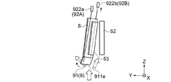
図10〜図12は、風向調整部9の動作を説明するための模式図であり、素子保持体8および風向調整部9の側面図である。具体的に、図10は、操作部922a,922bが操作されていない状態を示す図である。図11は、操作部922bが上方に移動された状態を示す図であり、図12は、操作部922aが上方に移動された状態を示す図である。
The wind
10 to 12 are schematic diagrams for explaining the operation of the wind
図10に示すように、風向調整部9は、操作部922a,922bが操作されていない状態で、風向変更部91の自重により本体部911が上下方向に沿った姿勢(所定の姿勢)で配置される所定の状態となる。
そして、所定の状態から操作部922bが上方に移動されると、風向変更部91は、ワイヤー921bに牽引され、図11に示すように、端部911eが液晶パネル52から遠ざかる方向に回動する。すなわち、風向変更部91は、端部911eと液晶パネル52との離間距離が所定の状態における離間距離より大きくなるように回動する。
As shown in FIG. 10, the wind
Then, when the
一方、所定の状態から操作部922aが上方に移動されると、風向変更部91は、図12に示すように、ワイヤー921aに牽引され、端部911eが液晶パネル52に近づく方向に回動する。すなわち、風向変更部91は、端部911eと液晶パネル52との離間距離が所定の状態における離間距離より小さくなるように回動する。
On the other hand, when the
また、移動部92A,92Bは、図示しない規制部によって移動可能な範囲が設定されている。そして、風向変更部91は、移動部92A,92Bの移動可能な範囲に対応する範囲で回動可能となる。
このように、風向調整部9は、操作部922a,922bの操作に応じて風向変更部91の回動する方向、および回動する量が調整される。これによって、液晶パネル52と補償素子53との間に流通する空気の風量が調整される。
In addition, the
Thus, the wind
風向調整部9を調整する作業者は、温度センサーTEの検出結果を確認しながら操作部922a,922bを操作する。
前述したように、第1状態においては、補償素子53とベース部621との距離が小さくなるので(図8参照)、所定の状態のままでは補償素子53と液晶パネル52との間に流通する風量が少なくなり、液晶パネル52は、温度が上昇する。そのため、作業者は、図11に示すように、操作部922bを上方に移動させ、補償素子53と液晶パネル52との間に流れる空気の風量を増加させる。その結果、液晶パネル52の温度上昇が抑制される。
An operator who adjusts the wind
As described above, in the first state, the distance between the
一方、第2状態においては、補償素子53とベース部621との距離が大きくなるので(図9参照)、所定の状態のままでは補償素子53と液晶パネル52との間に流通する空気の風量が多くなり、液晶パネル52は、温度が下降する。そのため、作業者は、図12に示すように、操作部922aを上方に移動させ、補償素子53と液晶パネル52との間に流れる空気の風量を減少させる。その結果、液晶パネル52の温度低下が抑制される。
なお、風向変更部91は、調整後に操作部922a,922bが図示しない部材に接着固定されることによって、調整された姿勢が維持される。
On the other hand, in the second state, the distance between the
The wind
このように、プロジェクター1は、風向調整部9が調整されることによって、ファンの駆動制御だけでは実現できなかった液晶パネル52の温度範囲をより狭い温度範囲で冷却することが可能となる。具体的には、応答性が良好で、かつ、熱劣化が抑制される温度範囲(例えば、約70°C〜約80°Cの範囲)で液晶パネル52を動作させることが可能となる。
As described above, the projector 1 can cool the temperature range of the
以上説明したように、本実施形態によれば、以下の効果を得ることができる。
(1)プロジェクター1は、補償素子53の傾きを調整できるので、画質を高めた画像の投写が可能となる。また、プロジェクター1は、風向調整部9を備えているので、ファンから送風された空気の流れを変え、液晶パネル52と補償素子53との間に流通する空気の風量を調整することができる。よって、補償素子53の傾き調整に伴って変わる液晶パネル52と補償素子53との離間距離に対応して双方の部材間に空気を流通させ、液晶パネル52および補償素子53を適切に冷却することが可能となる。
したがって、長期に亘って高画質の画像を投写するプロジェクター1の提供が可能となる。
As described above, according to the present embodiment, the following effects can be obtained.
(1) Since the projector 1 can adjust the inclination of the
Therefore, it is possible to provide the projector 1 that projects a high-quality image over a long period of time.
(2)風向調整部9は、風向変更部91に接続された移動部92A,92Bを備えているので、風向変更部91を簡素な構成で回動させ、液晶パネル52と補償素子53との間に流通させる空気の風量を容易に調整することが可能となる。
(2) Since the wind
(3)プロジェクター1は、第1操作部84および操作部922a,922b(第2操作部)が補償素子53に対して同じ側に配置されている。これによって、作業者は、補償素子53の傾き調整、および風向調整部9による空気の風量調整を、補償素子53の同一側から行うことができるので、2つの調整作業を効率的に行うことが可能となる。
また、補償素子53に対して第1操作部および操作部922a,922b(第2操作部)が配置されていない側に部材を配置できるので、素子保持体8が回動可能に保持部6に支持される構造や、保持部6が支持部7に支持される構造等をスペース効率よく構成することが可能となる。
(3) In the projector 1, the
Moreover, since a member can be arrange | positioned with respect to the
(4)風向変更部91は、端部911eと液晶パネル52との離間距離が所定の状態における離間距離より大きくなる回動が可能に構成されている。これによって、補償素子53の傾き調整によって液晶パネル52と補償素子53との距離が小さくなる場合であっても、液晶パネル52と補償素子53との間に適切に空気を流通させ、液晶パネル52と補償素子53を効率よく冷却することが可能となる。
(4) The wind
(5)風向変更部91は、端部911eと液晶パネル52との離間距離が所定の状態における離間距離より小さくなる回動が可能に構成されている。これによって、補償素子53の傾き調整によって液晶パネル52と補償素子53との距離が大きくなる場合であっても、液晶パネル52と補償素子53との間に流通させる空気の風量を制限し、液晶パネル52の過冷却を抑制することが可能となる。よって、プロジェクター1は、液晶パネル52を良好な応答性で駆動させることができるので、高速で切り替わる画像(例えば、3D画像(立体画像))の投写においても、良好な画像として観察者に視認させることが可能となる。
(5) The wind
(6)補償素子53の傾き調整は、対角方向に延出する対角軸7Jを中心とする回転方向の調整により行われる。これによって、液晶パネル52のプレチルト角(ラビング方向)に対応させて、補償素子53の傾きを調整できるので、投写される画像のコントラスト比や視野角特性を向上させることができる。よって、長期に亘って高画質の画像を投写するプロジェクター1の提供が可能となる。
(6) The inclination adjustment of the
(7)プロジェクター1は、温度センサーTEを備え、風向調整部9の調整は、この温度センサーTEの検出結果を確認しながら行われる。これによって、液晶パネル52を適正な温度範囲で冷却することをより確実に行うことが可能となる。
(7) The projector 1 includes the temperature sensor TE, and the adjustment of the wind
(変形例)
なお、前記実施形態は、以下のように変更してもよい。
前記実施形態の風向調整部9は、風向変更部91の端部911eと液晶パネル52との離間距離が所定の状態より大きくなる風向変更部91の回動、および所定の状態より小さくなる風向変更部91の回動を可能として構成されているが、この構成に限らない。風向変更部91が所定の状態における離間距離より大きくなる回動のみが可能となるように風向調整部を構成してもよい。この構成によれば、前述した実施形態の構成より簡素に風向調整部を構成し、補償素子53の傾き調整に伴って離間距離が小さくなる場合に液晶パネル52と補償素子53との間に空気を流通させ、液晶パネル52と補償素子53を冷却することが可能となる。
(Modification)
In addition, you may change the said embodiment as follows.
In the embodiment, the wind
前記実施形態の風向調整部9は、2つの移動部92A,92Bを備えているが、リンク機構等を利用して、1つの移動部で風向変更部91を回動させる構成であってもよい。
Although the wind
前記実施形態では、温度センサーTEの検出結果を確認しながら風向変更部91を調整するように構成されているが、この調整方法に限らない。例えば、第2屈曲部623(図8、図9参照)に目盛を施し、曲げ部841の位置に応じて風向変更部91を回動させる量を設定する等の構成が可能である。この構成の場合、プロジェクター1が温度センサーTEを備えない構成であっても、補償素子53の傾きに応じた風向変更部91の調整が可能となる。
In the above embodiment, the wind
前記実施形態の風向調整部9は、風向変更部91の自重で所定の状態(所定の姿勢)が設定されるように構成されているが、風向変更部が所定の位置で係止される構成とし、この係止される状態を所定の状態とする構成であってもよい。
The wind
前記実施形態の風向調整部9は、手動によって風向変更部91を回動させるように構成されているが、モーター等を備えた構成とし、電動で風向変更部91を回動させる態様であってもよい。
Although the wind
前記実施形態のプロジェクター1は、3つの電気光学装置50R,50G,50Bそれぞれが補償素子53を備えているが、3つのうちのいずれかが補償素子53を備える構成であってもよい。例えば、電気光学装置50Gが補償素子53を備え、電気光学装置50R,50Bが補償素子53を備えない構成であってもよい。この構成の場合、電気光学装置50Gは、素子保持体8および風向調整部9を備え、電気光学装置50R,50Bは、素子保持体8および風向調整部9を備えない構成となる。
In the projector 1 of the embodiment, each of the three electro-
前記実施形態では、液晶パネル52に対向し、光軸52Gjに対する傾きを調整可能な光学素子として補償素子53が用いられているが、補償素子53に限らず他の光学部品を光学素子として構成してもよい。
また、前記実施形態では、光学素子が液晶パネル52の光射出側に配置されているが、液晶パネル52の光入射側に配置されるように構成してもよい。
In the embodiment, the
In the embodiment, the optical element is disposed on the light emission side of the
前記実施形態では、対角方向に延出する対角軸7Jを中心とする回動で補償素子53の傾きが調整されるように構成されているが、X方向やZ方向に沿う軸を中心とする回動で傾きが調整される構成であってもよい。
In the above embodiment, the tilt of the
前記実施形態のプロジェクター1は、光変調装置として透過型の液晶パネル52を用いているが、反射型の液晶パネルを利用したものであってもよい。
The projector 1 according to the embodiment uses the transmissive
前記実施形態の光源装置31は、放電型の光源311を採用しているが、その他の方式の光源や発光ダイオード、レーザー等の固体光源で構成してもよい。
The
1…プロジェクター、6…保持部、7…支持部、7J…対角軸、8…素子保持体、9…風向調整部、31…光源装置、52…液晶パネル(光変調装置)、52Gj…光軸、53…補償素子(光学素子)、81…取付部、84…第1操作部、91…風向変更部、92A,92B…移動部、311…光源、912…軸支部、921a,921b…ワイヤー(延出部)、922a,922b…操作部(第2操作部)。
DESCRIPTION OF SYMBOLS 1 ... Projector, 6 ... Holding part, 7 ... Supporting part, 7J ... Diagonal axis, 8 ... Element holding body, 9 ... Wind direction adjusting part, 31 ... Light source device, 52 ... Liquid crystal panel (light modulation device), 52Gj ... Light Axis 53: Compensating element (optical element) 81 ... Mounting
Claims (6)
前記光源から射出された光を画像情報に応じて変調する光変調装置と、
前記光変調装置を保持する保持部と、
前記光変調装置に対向して配置され、入射する光を光学的に変換する光学素子と、
前記光学素子を保持する素子保持体と、
前記光変調装置と前記光学素子との間に流通する空気の風量を調整する風向調整部と、
を備え、
前記素子保持体は、前記光変調装置の光軸に対する前記光学素子の傾きを調整可能に前記保持部に支持され、
前記風向調整部は、一端が前記素子保持体に回動可能に支持され、前記光学素子に向かう空気の流れを変える風向変更部を備えることを特徴とするプロジェクター。 A light source;
A light modulation device that modulates light emitted from the light source according to image information;
A holding unit for holding the light modulation device;
An optical element disposed opposite to the light modulator and optically converting incident light;
An element holder for holding the optical element;
A wind direction adjusting unit that adjusts the amount of air flowing between the light modulation device and the optical element;
With
The element holding body is supported by the holding portion so that the inclination of the optical element with respect to the optical axis of the light modulation device can be adjusted,
The projector is characterized in that one end of the wind direction adjusting unit is rotatably supported by the element holding body and includes a wind direction changing unit that changes a flow of air toward the optical element.
前記風向変更部は、前記一端に前記素子保持体に回動可能に支持される軸支部を有し、
前記風向調整部は、前記風向変更部の前記軸支部とは離れた位置に接続された移動部を備え、
前記移動部は、前記軸支部の回転中心軸に交差する方向に移動可能であることを特徴とするプロジェクター。 The projector according to claim 1,
The wind direction changing part has a shaft support part rotatably supported by the element holding body at the one end.
The wind direction adjusting unit includes a moving unit connected to a position away from the shaft support unit of the wind direction changing unit,
The projector according to claim 1, wherein the moving unit is movable in a direction intersecting with a rotation center axis of the shaft support.
前記素子保持体は、前記光学素子が取り付けられる取付部、および前記取付部から前記光軸に交差する方向に延出し、前記傾きを調整するために操作される第1操作部を有し、
前記移動部は、前記風向変更部に接続され、前記光軸に交差する方向に延出する延出部、および前記延出部の前記風向変更部に接続された部位とは反対側となる端部側に設けられ、移動のために操作される第2操作部を有し、
前記第1操作部および前記第2操作部は、前記光学素子に対し、同じ側に配置されていることを特徴とするプロジェクター。 The projector according to claim 2,
The element holding body includes a mounting portion to which the optical element is mounted, and a first operation portion that extends from the mounting portion in a direction intersecting the optical axis and is operated to adjust the inclination.
The moving part is connected to the wind direction changing part and extends in a direction crossing the optical axis, and an end of the extending part opposite to the part connected to the wind direction changing part A second operating unit that is provided on the part side and is operated for movement;
The projector according to claim 1, wherein the first operation unit and the second operation unit are disposed on the same side with respect to the optical element.
前記風向調整部は、前記風向変更部が所定の姿勢で配置される所定の状態を有し、
前記風向変更部は、前記一端とは反対側となる他端と前記光変調装置との離間距離が前記所定の状態における前記離間距離より大きくなる回動が可能であることを特徴とするプロジェクター。 It is a projector as described in any one of Claims 1-3, Comprising:
The wind direction adjusting unit has a predetermined state in which the wind direction changing unit is arranged in a predetermined posture,
The projector is characterized in that the wind direction changing unit is capable of rotating such that a separation distance between the other end opposite to the one end and the light modulation device is larger than the separation distance in the predetermined state.
前記風向変更部は、前記離間距離が前記所定の状態における前記離間距離より小さくなる回動が可能であることを特徴とするプロジェクター。 The projector according to claim 4,
The projector is characterized in that the wind direction changing unit can be rotated so that the separation distance is smaller than the separation distance in the predetermined state.
前記光変調装置は、液晶パネルであり、
前記光学素子は、前記液晶パネルの光射出側に配置され、前記液晶パネルから射出された光の位相差を補償する補償素子であり、
前記傾きの調整は、前記補償素子の対角方向に延出する対角軸を中心とする回転方向の調整により行われることを特徴とするプロジェクター。 It is a projector as described in any one of Claims 1-5, Comprising:
The light modulation device is a liquid crystal panel,
The optical element is a compensation element that is disposed on a light emission side of the liquid crystal panel and compensates for a phase difference of light emitted from the liquid crystal panel.
The projector is characterized in that the tilt adjustment is performed by adjusting a rotation direction around a diagonal axis extending in a diagonal direction of the compensation element.
Priority Applications (1)
| Application Number | Priority Date | Filing Date | Title |
|---|---|---|---|
| JP2016076371A JP2017187624A (en) | 2016-04-06 | 2016-04-06 | projector |
Applications Claiming Priority (1)
| Application Number | Priority Date | Filing Date | Title |
|---|---|---|---|
| JP2016076371A JP2017187624A (en) | 2016-04-06 | 2016-04-06 | projector |
Publications (1)
| Publication Number | Publication Date |
|---|---|
| JP2017187624A true JP2017187624A (en) | 2017-10-12 |
Family
ID=60045509
Family Applications (1)
| Application Number | Title | Priority Date | Filing Date |
|---|---|---|---|
| JP2016076371A Pending JP2017187624A (en) | 2016-04-06 | 2016-04-06 | projector |
Country Status (1)
| Country | Link |
|---|---|
| JP (1) | JP2017187624A (en) |
-
2016
- 2016-04-06 JP JP2016076371A patent/JP2017187624A/en active Pending
Similar Documents
| Publication | Publication Date | Title |
|---|---|---|
| KR200314521Y1 (en) | Rear projector | |
| CN101261358B (en) | Projection display device | |
| KR100643977B1 (en) | Optical device and projector having the optical device | |
| US20120008097A1 (en) | Manufacturing method of projection apparatus, manufacturing equipment of projection apparatus, and projection apparatus | |
| JP5002319B2 (en) | Projection display | |
| JP5790206B2 (en) | projector | |
| CN104169780A (en) | Vehicle display device | |
| JP3702890B2 (en) | Optical assembly and projector | |
| JP6958062B2 (en) | Image generation unit, image projection device and heat sink | |
| US8840252B2 (en) | Image display apparatus and portable information processing apparatus having the same | |
| JP2017187624A (en) | projector | |
| JP2009192971A (en) | Projector and adjustment method | |
| JP5725221B2 (en) | projector | |
| JP6668635B2 (en) | Optical compensation element adjustment mechanism and projector | |
| EP3707545B1 (en) | Projector and operating method thereof | |
| JP5516168B2 (en) | projector | |
| JP2009198539A (en) | Projector and adjusting method | |
| JP5644142B2 (en) | projector | |
| JP5540929B2 (en) | projector | |
| JP2014041176A (en) | Projector | |
| JP5115365B2 (en) | Optical device and projector | |
| JP2004246059A (en) | Optical component housing, optical unit, and projector | |
| JP2004205715A (en) | Lens support structure, projection optical device, and projector | |
| JP2018017961A (en) | projector | |
| JP2016012135A (en) | projector |
Legal Events
| Date | Code | Title | Description |
|---|---|---|---|
| RD05 | Notification of revocation of power of attorney |
Free format text: JAPANESE INTERMEDIATE CODE: A7425 Effective date: 20180906 |
|
| RD03 | Notification of appointment of power of attorney |
Free format text: JAPANESE INTERMEDIATE CODE: A7423 Effective date: 20181119 |