JP2017187677A - Sound absorbing material mounting structure, sound absorbing material mounting method, and portable container - Google Patents
Sound absorbing material mounting structure, sound absorbing material mounting method, and portable container Download PDFInfo
- Publication number
- JP2017187677A JP2017187677A JP2016077303A JP2016077303A JP2017187677A JP 2017187677 A JP2017187677 A JP 2017187677A JP 2016077303 A JP2016077303 A JP 2016077303A JP 2016077303 A JP2016077303 A JP 2016077303A JP 2017187677 A JP2017187677 A JP 2017187677A
- Authority
- JP
- Japan
- Prior art keywords
- absorbing material
- sound absorbing
- angle member
- wall surface
- portable container
- Prior art date
- Legal status (The legal status is an assumption and is not a legal conclusion. Google has not performed a legal analysis and makes no representation as to the accuracy of the status listed.)
- Granted
Links
Images






Landscapes
- Soundproofing, Sound Blocking, And Sound Damping (AREA)
Abstract
Description
本開示は、吸音材の取付け構造、吸音材の取付け方法、および該吸音材の取付け構造を備える可搬式容器に関する。 The present disclosure relates to a sound absorbing material mounting structure, a sound absorbing material mounting method, and a portable container including the sound absorbing material mounting structure.
近年、非常・緊急対応用の電源需要および分散型の電源需要に対応する発電設備として、コンテナなどの可搬式容器に発電設備が収容された可搬式発電ユニットが注目を浴びている。かかる発電ユニットは、発電機や、発電機を駆動するための動力発生源(例えばエンジンやタービン)などの発電設備が収容されたコンテナ(発電コンテナ)を、トレーラなどの輸送機器によって現地まで搬送されることで、使用される。また、発電設備が収容されたコンテナとは別に、動力発生源から排出される排熱を回収するための熱交換器(例えば排熱回収ボイラ)などの周辺機器類が収容されたコンテナ(排熱回収コンテナ)を併用することで、コジェネレーション(熱電併給)にも対応することが出来るようになっている。 2. Description of the Related Art In recent years, portable power generation units in which power generation facilities are accommodated in portable containers such as containers have attracted attention as power generation facilities that respond to emergency and emergency power demands and distributed power demands. Such a power generation unit is transported to the site by a transport device such as a trailer, in which a power generation facility such as a power generator or a power generation source (for example, an engine or a turbine) for driving the power generator is accommodated. Used. In addition to containers that contain power generation equipment, containers that contain peripheral equipment such as heat exchangers (for example, waste heat recovery boilers) that recover exhaust heat exhausted from power generation sources (exhaust heat) By using a collection container in combination, cogeneration (cogeneration) can be supported.
このような発電コンテナや排熱回収コンテナには、エンジンやタービン、および排熱回収ボイラなどの騒音発生源から発生する騒音が、コンテナの外部に漏れ伝わるのを防ぐ目的で、その内壁パネルに吸音材が設置されている。 In such a power generation container and exhaust heat recovery container, the noise generated from noise sources such as engines, turbines, and exhaust heat recovery boilers is not absorbed into the inner wall panel for the purpose of preventing the noise from leaking outside the container. The material is installed.
従来、内壁パネルに吸音材を取付ける方法として、補強用のアングル部材をその全長に亘って内壁パネルに溶接(TIG溶接、MIG溶接、またはMAG溶接)によって固定し、この固定された補強用のアングル部材に対して吸音材をリベットなどで取付ける方法が採られていた。 Conventionally, as a method of attaching a sound absorbing material to an inner wall panel, a reinforcing angle member is fixed to the inner wall panel by welding (TIG welding, MIG welding, or MAG welding) over the entire length thereof, and this fixed reinforcing angle. A method of attaching a sound absorbing material to a member with a rivet or the like has been adopted.
しかしながら、上述した従来の取付け方法では、アングル部材の溶接作業に多大な労力を要していた他、溶接による焼け跡を除去するためにグラインダ研磨などを行う必要があるなど、大変手間のかかるものであった。また、アングル部材が、その全長に亘って内壁パネルに溶接されるため、内壁パネルに残留ひずみが生じる場合があった。内壁パネルに残留ひずみが生じた場合には、そのひずみを除去する工程が必要となり、さらに手間を要していた。また、アングル部材を取り外すことが出来ないため、吸音材を交換する際には内壁パネル自体を取り外す必要があり、交換性に劣るものであった。 However, in the conventional mounting method described above, much work is required for the welding work of the angle member, and it is necessary to perform grinder polishing in order to remove burn marks caused by welding. there were. Moreover, since the angle member is welded to the inner wall panel over the entire length thereof, residual strain may occur in the inner wall panel. When residual strain occurs in the inner wall panel, a process for removing the strain is required, and further labor is required. Further, since the angle member cannot be removed, it is necessary to remove the inner wall panel itself when exchanging the sound absorbing material, resulting in poor exchangeability.
特許文献1には、自動車などの車室内に吸音材を取付ける吸音材取付け構造に関する発明が開示されている。この特許文献1に開示されている吸音材の取付け構造では、吸音材にスリット部を形成するとともに、内装パネル部材の裏面側に、スリット部と対応してスリット部内へ挿入可能な縦リブ部を立設し、この縦リブの先端部に吸音材を係止可能な横リブを設けている。しかしながら、この特許文献1に開示されている吸音材の取付け構造では、複数の縦リブの各々を内装パネル部材にそれぞれ立設する必要があり、その製作に手間のかかるものであった。また、吸音材にスリット部を形成するため、吸音性能が低下するとの問題があった。
本発明は、上述したような従来の課題の下になされた発明であって、その目的とするところは、簡単かつ迅速な方法で内壁パネルに吸音材を取付けることの出来る吸音材の取付け構造、吸音材の取付け方法、および該吸音材の取付け構造を備える可搬式容器を提供することにある。 The present invention is an invention made under the conventional problems as described above, and its object is to attach a sound absorbing material to an inner wall panel in a simple and quick manner, An object of the present invention is to provide a method for attaching a sound absorbing material and a portable container provided with a structure for attaching the sound absorbing material.
(1)本発明の一実施形態にかかる吸音材の取付け構造は、
壁面に吸音材を取付ける吸音材取付け構造であって、
前記壁面にスタッド溶接されたスタッドバーと、
前記スタッドバーが挿通される貫通穴を有するアングル部材であって、前記貫通穴に前記スタッドバーが挿通された状態で前記スタッドバーと結合されることで、前記壁面に固定されるアングル部材と、
前記アングル部材に設けられ、前記壁面との間で前記吸音材を挟持するための押え部と、を備える。
(1) A sound absorbing material mounting structure according to an embodiment of the present invention is as follows:
A sound absorbing material mounting structure for attaching a sound absorbing material to a wall surface,
A stud bar stud-welded to the wall surface;
An angle member having a through hole through which the stud bar is inserted, and an angle member fixed to the wall surface by being coupled to the stud bar in a state where the stud bar is inserted into the through hole;
A presser portion provided on the angle member and sandwiching the sound absorbing material between the wall surface.
上記(1)に記載の実施形態によれば、壁面にスタッド溶接されたスタッドバーにアングル部材が結合されることで、アングル部材が壁面に固定される。そして、この壁面に固定されたアングル部材に設けられた押え部と壁面との間に吸音材が挟持されることで、吸音材が壁面に取付けられる。 According to the embodiment described in (1) above, the angle member is fixed to the wall surface by coupling the angle member to the stud bar stud-welded to the wall surface. And a sound-absorbing material is attached to a wall surface by pinching a sound-absorbing material between the press part provided in the angle member fixed to this wall surface, and a wall surface.
したがって、従来の取付け方法と比べて、アングル部材をその全長に亘って壁面に溶接する必要がないことから、溶接に要していた時間を大幅に短縮することが出来る。また、スタッド溶接を採用したことにより、従来の取付け方法と比べて、溶接による熱影響を最小限に抑えることができる。このため、溶接による焼け跡の除去や、残留ひずみの除去を行う必要がなく、作業時間を更に低減することが出来る。また、スタッド溶接を採用したことにより、従来の取付け方法のように溶接資格といった組立工員の制限がなくなる。 Therefore, compared with the conventional attachment method, it is not necessary to weld the angle member to the wall surface over the entire length thereof, so that the time required for welding can be greatly shortened. In addition, by adopting stud welding, the thermal effect due to welding can be minimized as compared with the conventional attachment method. For this reason, it is not necessary to remove the burn mark by welding or to remove the residual strain, and the working time can be further reduced. In addition, by adopting stud welding, there is no restriction on assembly personnel such as welding qualification as in the conventional mounting method.
これらにより、従来の取付け方法と比べて、簡単かつ迅速な方法で壁面に吸音材を取付けることが出来るようになっている。 As a result, it is possible to attach the sound-absorbing material to the wall surface in a simpler and quicker manner than the conventional attachment method.
しかも、壁面とアングル部材とが直接溶接されているのではなく、壁面にスタッド溶接されたスタッドバーに対してアングル部材が固定される。このため、従来の取付け方法と比べて、アングル部材の取り外しが容易となり、吸音材を交換する際の作業性を大幅に向上させることが出来る。 Moreover, the wall surface and the angle member are not directly welded, but the angle member is fixed to a stud bar that is stud welded to the wall surface. For this reason, compared with the conventional attachment method, removal of an angle member becomes easy and workability | operativity at the time of replacing | exchanging a sound absorption material can be improved significantly.
(2)幾つかの実施形態では、上記(1)に記載の吸音材の取付け構造において、上記アングル部材は、壁面に対して交差する方向に延在するウェブ部と、貫通穴が形成された、ウェブ部の一端側に接続する基端側フランジ部と、を含む。そして、押え部は、ウェブ部の他端側に設けられた、壁面に対して平行な方向に延在する板状部材からなる。 (2) In some embodiments, in the sound absorbing material mounting structure according to (1), the angle member has a web portion extending in a direction intersecting the wall surface and a through hole. And a proximal end flange portion connected to one end side of the web portion. And the press part consists of a plate-shaped member provided in the other end side of the web part and extending in a direction parallel to the wall surface.
上記(2)に記載の実施形態によれば、上記アングル部材は、壁面に対して交差する方向に延在するウェブ部と、貫通穴が形成された、ウェブ部の一端側に接続する基端側フランジ部と、を含む。このようなアングル部材としては、例えば、H形鋼、I形鋼、L形鋼、Z形鋼、C形(溝形)鋼などの一般に流通する形鋼、および平板からプレス加工などで曲げを形成した各種のアングル部材を使用することが出来る。さらに、アングル部材は補強材としての役割を持たせることもでき、必要な強度が確保できる形状を適宜選択できる。 According to the embodiment described in the above (2), the angle member includes a web portion extending in a direction intersecting the wall surface, and a proximal end connected to one end side of the web portion in which a through hole is formed. A side flange portion. As such angle members, for example, H-shaped steel, I-shaped steel, L-shaped steel, Z-shaped steel, C-shaped (grooved) steel, and other commonly used shape steel, and bending from a flat plate by pressing, etc. Various formed angle members can be used. Furthermore, the angle member can also have a role as a reinforcing material, and a shape that can ensure the necessary strength can be selected as appropriate.
また、上記押え部が、ウェブ部の他端側に設けられた、壁面に対して平行な方向に延在する板状部材からなる。このため、押え部と壁面との間に吸音材を安定して保持することができる。 Moreover, the said press part consists of a plate-shaped member provided in the other end side of the web part, and extended in the direction parallel to a wall surface. For this reason, a sound-absorbing material can be stably held between the presser portion and the wall surface.
(3)幾つかの実施形態では、上記(2)に記載の吸音材の取付け構造において、上記押え部は、アングル部材と一体に形成された、ウェブ部の他端側に接続する先端側フランジ部からなる。 (3) In some embodiments, in the sound absorbing material mounting structure according to (2), the pressing portion is formed integrally with the angle member, and is connected to the other end side of the web portion. Consists of parts.
上記(3)に記載の実施形態によれば、押え部として、アングル部材と一体に形成された、ウェブ部の他端側に接続する先端側フランジ部を採用することで、押え部をアングル部材とは別体の部材から構成する場合と比べて、部品点数を少なくすることができる。 According to the embodiment described in the above (3), by adopting the front end side flange portion that is integrally formed with the angle member and connected to the other end side of the web portion as the press portion, the press portion is attached to the angle member. The number of parts can be reduced compared with the case where it comprises from a separate member.
(4)幾つかの実施形態では、上記(2)に記載の吸音材の取付け構造において、上記押え部は、アングル部材と別体に形成された、ウェブ部の他端側に固定された押え板からなる。 (4) In some embodiments, in the sound absorber mounting structure described in (2) above, the presser portion is formed separately from the angle member and is fixed to the other end side of the web portion. It consists of a plate.
上記(4)に記載の実施形態によれば、押え部として、アングル部材と別体に形成された、ウェブ部の他端側に取付けられた押え板を採用することで、押え板と壁面との間で吸音材を挟持することができる。また、押え板が取付けられていない状態のアングル部材をスタッドバーに固定することで、アングル部材をスタッドバーに固定する際の作業性が向上する。また、アングル部材に吸音材が取付けられた状態で、押え板をアングル部材に固定することで、吸音材に厚みや大きさに柔軟に対応可能な取付け構造とすることができる。 According to the embodiment described in the above (4), the presser plate and the wall surface are formed by adopting the presser plate attached to the other end side of the web part, which is formed separately from the angle member, as the presser part. Sound absorbing material can be held between the two. Moreover, workability | operativity at the time of fixing an angle member to a stud bar improves by fixing the angle member in the state where the presser plate is not attached to a stud bar. Further, by fixing the presser plate to the angle member in a state where the sound absorbing material is attached to the angle member, it is possible to provide an attachment structure that can flexibly cope with the thickness and size of the sound absorbing material.
(5)幾つかの実施形態では、上記(2)に記載の吸音材の取付け構造において、上記押え部は、アングル部材と一体に形成された、ウェブ部の他端側に接続する先端側フランジ部と、アングル部材と別体に形成された、先端側フランジ部に固定された押え板と、からなる。 (5) In some embodiments, in the sound absorbing material mounting structure according to (2), the pressing portion is formed integrally with the angle member, and is connected to the other end side of the web portion. And a presser plate formed separately from the angle member and fixed to the flange portion on the front end side.
上記(5)に記載の実施形態によれば、押え部として、アングル部材と一体に形成された、ウェブ部の他端側に接続する先端側フランジ部、およびアングル部材と別体に形成された、先端側フランジ部に固定された押え板、の両方を採用することで、上述した(3)および(4)に記載した両方の作用効果を奏し得るとともに、先端側フランジ部と押え板との両方によって、壁面との間で吸音材を挟持することができる。 According to the embodiment described in the above (5), the presser portion is formed integrally with the angle member, and is formed separately from the front end side flange portion connected to the other end side of the web portion and the angle member. By adopting both of the presser plate fixed to the front end side flange portion, both the effects described in (3) and (4) above can be achieved, and the front end side flange portion and the presser plate By both, a sound-absorbing material can be clamped between the wall surfaces.
(6)幾つかの実施形態では、上記(3)または(5)に記載の吸音材の取付け構造において、上記基端側フランジ部は、ウェブ部から一方側に向かって延在する。そして、先端側フランジ部は、ウェブ部から、一方側とは反対側である他方側に向かって延在する。 (6) In some embodiments, in the sound absorbing material mounting structure according to (3) or (5), the proximal end flange portion extends from the web portion toward one side. The distal flange portion extends from the web portion toward the other side opposite to the one side.
上記(6)に記載の実施形態によれば、アングル部材の基端側フランジ部と先端側フランジ部とが互いに逆向きにウェブ部から延在している。これにより、スタッドバーの延在方向の延長線上に先端側フランジ部が位置しないため、アングル部材をスタッドバーに固定する際に、先端側フランジ部が固定作業の障害とはならない。よって、アングル部材をスタッドバーに固定する際の作業性が優れている。 According to the embodiment described in (6) above, the proximal end flange portion and the distal end flange portion of the angle member extend from the web portion in opposite directions. Thereby, since a front end side flange part is not located on the extension line of the extension direction of a stud bar, when fixing an angle member to a stud bar, a front end side flange part does not become an obstacle of fixing work. Therefore, workability when fixing the angle member to the stud bar is excellent.
(7)幾つかの実施形態では、上記(4)に記載の吸音材の取付け構造において、上記押え板は、ウェブ部に対して垂直な方向に挿通されたリベットまたはビスによって、ウェブ部に固定される。そして、リベットまたはビスの先端は、吸音材に当接する。 (7) In some embodiments, in the sound absorbing material mounting structure according to the above (4), the pressing plate is fixed to the web portion by rivets or screws inserted in a direction perpendicular to the web portion. Is done. The tip of the rivet or screw comes into contact with the sound absorbing material.
上記(7)に記載の実施形態によれば、リベットまたはビスによって、押え板をアングル部材のウェブ部に容易に固定することができるとともに、このリベットまたはビスの先端を吸音材に当接させることで、吸音材のズレや脱落などを効果的に防止することができる。 According to the embodiment described in (7) above, the holding plate can be easily fixed to the web portion of the angle member by the rivet or the screw, and the tip of the rivet or the screw is brought into contact with the sound absorbing material. Therefore, it is possible to effectively prevent the sound absorbing material from shifting or dropping off.
(8)幾つかの実施形態では、上記(5)に記載の吸音材の取付け構造において、上記押え板は、先端側フランジ部に対して垂直な方向に挿通されたリベットまたはビスによって、先端側フランジ部に固定される。そして、リベットまたはビスの先端は、吸音材に当接する。 (8) In some embodiments, in the sound absorbing material mounting structure according to (5), the pressing plate has a distal end side formed by a rivet or a screw inserted in a direction perpendicular to the distal end flange portion. Fixed to the flange. The tip of the rivet or screw comes into contact with the sound absorbing material.
上記(8)に記載の実施形態によれば、リベットまたはビスによって、押え板をアングル部材の先端側フランジ部に容易に固定することができるとともに、このリベットまたはビスの先端を吸音材に当接させることで、吸音材のズレや脱落などを効果的に防止することができる。 According to the embodiment described in the above (8), the presser plate can be easily fixed to the front end side flange portion of the angle member by the rivet or the screw, and the front end of the rivet or the screw is brought into contact with the sound absorbing material. By doing so, it is possible to effectively prevent the sound absorbing material from shifting or dropping off.
(9)幾つかの実施形態では、上記(1)から(8)のいずれか1つに記載の取付け構造において、上記スタッドバーは、軸部にネジ溝が形成されたスタッドボルトからなる。アングル部材は、スタッドボルトに螺着されたナットによって、スタッドボルトに結合される。そして、ネジ溝のピッチは、JIS
B 0207(1999)に規定される細目ネジのピッチと同じか、それ未満である。
(9) In some embodiments, in the attachment structure described in any one of (1) to (8) above, the stud bar is formed of a stud bolt in which a thread groove is formed in a shaft portion. The angle member is coupled to the stud bolt by a nut screwed to the stud bolt. And the pitch of the thread groove is JIS
It is the same as or less than the pitch of the fine thread defined in B 0207 (1999).
上記(9)に記載の実施形態によれば、スタッドバー(スタッドボルト)とアングル部材とをボルト締結によって簡単に結合することができる。また、ネジ溝のピッチを細目ネジのピッチと同じか、それ未満とすることで、スタッドバーとアングル部材とを強固に結合することができ、振動などによって締結部が緩んでしまうことを防ぐことができる。 According to the embodiment described in (9) above, the stud bar (stud bolt) and the angle member can be easily coupled by bolt fastening. In addition, by setting the pitch of the thread groove to be the same as or less than the pitch of the fine screw, the stud bar and the angle member can be firmly coupled to prevent the fastening portion from being loosened due to vibration or the like. Can do.
(10)本発明の一実施形態にかかる可搬式容器は、
輸送機器によって搬送可能な可搬式容器であって、
前記可搬式容器は、騒音発生源を収容し、
前記可搬式容器の内壁パネルには、上記(1)から(9)の何れか1つに記載の吸音材の取付け構造によって吸音材が取付けられている。
(10) A portable container according to an embodiment of the present invention is:
A portable container that can be transported by a transport device,
The portable container contains a noise source,
The sound absorbing material is attached to the inner wall panel of the portable container by the sound absorbing material mounting structure described in any one of (1) to (9) above.
上記(10)に記載の実施形態によれば、輸送機器によって搬送可能な可搬式容器において、その内壁パネルに吸音材を取付けることで、可搬式容器の内部に収容される騒音発生源からの騒音が外部に漏れ伝わるのを防止することができる。 According to the embodiment described in the above (10), in the portable container that can be transported by the transport equipment, the noise from the noise generation source housed in the portable container can be obtained by attaching the sound absorbing material to the inner wall panel. Can be prevented from leaking to the outside.
また、可搬式容器は、想定される各種の荷重に耐え得るような強度を有している必要がある。特に可搬式容器は、例えばトレーラなどの輸送機器によって搬送されるため、輸送時における振動荷重などに対して耐え得るような強度を有している必要がある。
この点、上記(10)に記載の実施形態によれば、スタッドバーを介して内壁パネルに固定されるアングル部材が補強材としての役割を果たすため、内壁パネルの剛性を高めることができる。
Moreover, the portable container needs to have a strength that can withstand various loads assumed. In particular, since the portable container is transported by a transportation device such as a trailer, it needs to have a strength that can withstand a vibration load during transportation.
In this regard, according to the embodiment described in (10) above, the angle member fixed to the inner wall panel via the stud bar plays a role as a reinforcing material, and therefore the rigidity of the inner wall panel can be increased.
(11)幾つかの実施形態では、上記(10)に記載の可搬式容器において、上記可搬式容器は、発電機を収容する。そして、騒音発生源は、発電機を駆動するための動力発生源からなる。 (11) In some embodiments, in the portable container described in (10) above, the portable container houses a generator. The noise generation source includes a power generation source for driving the generator.
上記(11)に記載の実施形態によれば、可搬式容器が、発電機や、発電機を駆動するための動力発生源(例えばエンジンやタービン)などの発電設備が収容された可搬式発電ユニットの可搬式容器として構成される。このように、本発明の可搬式容器は、可搬式発電ユニットの可搬式容器としても、好適に用いられるものである。 According to the embodiment described in (11) above, the portable container is a portable power generation unit in which power generation equipment such as a power generator or a power generation source (for example, an engine or a turbine) for driving the power generator is accommodated. It is configured as a portable container. Thus, the portable container of this invention is used suitably also as a portable container of a portable power generation unit.
(12)幾つかの実施形態では、上記(10)に記載の可搬式容器において、上記可搬式容器は、動力発生源から排出される排熱を回収するための排熱回収装置を収容する。そして、騒音発生源は、排熱回収装置からなる。 (12) In some embodiments, in the portable container described in (10) above, the portable container accommodates an exhaust heat recovery device for recovering exhaust heat exhausted from a power generation source. The noise generation source includes an exhaust heat recovery device.
上記(12)に記載の実施形態によれば、可搬式容器は、排熱回収装置を収容し、騒音発生源は、動力発生源から排出される排熱を回収するための排熱回収装置(例えば排熱回収ボイラ)からなる。すなわち、本実施形態の可搬式容器は、排熱回収装置などの周辺機器類が収容された可搬式熱回収ユニットの可搬式容器として構成される。このように、本発明の可搬式容器は、可搬式熱回収ユニットの可搬式容器としても、好適に用いられるものである。 According to the embodiment described in the above (12), the portable container accommodates the exhaust heat recovery device, and the noise generation source recovers the exhaust heat exhausted from the power generation source ( For example, an exhaust heat recovery boiler). That is, the portable container of this embodiment is configured as a portable container of a portable heat recovery unit in which peripheral devices such as an exhaust heat recovery device are accommodated. Thus, the portable container of this invention is used suitably also as a portable container of a portable heat recovery unit.
(13)幾つかの実施形態では、上記(11)または(12)の何れか1つに記載の可搬式容器において、上記可搬式容器は、鉛直方向に開口する通気口を有するフード部を有する。そして、上記アングル部材は、フード部において、少なくともアングル部材の一部が鉛直方向に沿って延在する。 (13) In some embodiments, in the portable container according to any one of (11) and (12), the portable container includes a hood portion having a vent opening that opens in a vertical direction. . In the hood portion, at least a part of the angle member extends along the vertical direction.
エンジンやタービンなどの動力発生源や、排熱回収ボイラなどの排熱回収装置を収容する可搬式容器においては、それら機器を冷却するための冷却空気を外部から導入する必要がある。
上記(13)に記載の実施形態によれば、水平方向ではなく鉛直方向に通気口を開口させることで、通気口から漏れ伝わる騒音が可搬式容器の周囲に響くのを防止している。また、鉛直方向に開口する通気口を有するフード部の内部では、空気は鉛直方向に沿って流れることとなる。よって、空気の流れる鉛直方向に沿って少なくともアングル部材の一部を延在させることで、アングル部材が空気流に対して抵抗になることを抑制することができる。
In a portable container that houses a power generation source such as an engine or a turbine, or a waste heat recovery device such as a waste heat recovery boiler, it is necessary to introduce cooling air for cooling these devices from the outside.
According to the embodiment described in (13) above, by opening the vent in the vertical direction instead of in the horizontal direction, noise leaking from the vent is prevented from reverberating around the portable container. Moreover, in the inside of the hood part which has a vent hole opened in a perpendicular direction, air will flow along a perpendicular direction. Therefore, by extending at least a part of the angle member along the vertical direction in which the air flows, the angle member can be prevented from becoming resistant to the air flow.
(14)本発明の一実施形態にかかる吸音材の取付け方法は、
壁面に吸音材を取付ける吸音材取付け方法であって、
前記壁面にスタッドバーをスタッド溶接するステップと、
前記スタッドバーが挿通される貫通穴を有するアングル部材を、前記貫通穴に前記スタッドバーが挿通された状態で前記スタッドバーと結合し、前記壁面に固定するステップと、
前記アングル部材に設けられる押え部と、前記壁面との間で、前記吸音材を挟持するステップと、を備える。
(14) A method for attaching a sound absorbing material according to an embodiment of the present invention is as follows:
A sound absorbing material mounting method for attaching a sound absorbing material to a wall surface,
Stud welding a stud bar to the wall surface;
An angle member having a through-hole through which the stud bar is inserted, and the stud bar is coupled to the stud bar in a state where the stud bar is inserted into the through-hole, and fixed to the wall surface;
A step of sandwiching the sound absorbing material between a pressing portion provided in the angle member and the wall surface.
上記(14)に記載の実施形態によれば、上記(1)に記載の吸音材の取付け構造と同様に、簡単かつ迅速な方法で壁面に吸音材を取付けることが出来る。 According to the embodiment described in the above (14), the sound absorbing material can be attached to the wall surface by a simple and quick method, similarly to the sound absorbing material mounting structure described in the above (1).
(15)幾つかの実施形態では、上記(14)に記載の吸音材の取付け方法において、上記溶接ステップの前に、壁面におけるスタッドバーが溶接される位置に、予めポンチ穴を加工するステップをさらに備える。 (15) In some embodiments, in the method for attaching the sound absorbing material according to (14), a step of machining a punch hole in advance at a position where the stud bar on the wall surface is welded is performed before the welding step. Further prepare.
上記(15)に記載の実施形態によれば、壁面におけるスタッドバーが溶接される位置に、予めポンチ穴が加工される。このため、スタッドバーをスタッド溶接する際に、その位置出しおよび位置決めが容易となる。 According to the embodiment described in (15) above, the punch hole is processed in advance at the position where the stud bar on the wall surface is welded. For this reason, when the stud bar is stud welded, its positioning and positioning are facilitated.
本発明の少なくとも一つの実施形態によれば、簡単かつ迅速な方法で内壁パネルに吸音材を取付けることの出来る吸音材の取付け構造、吸音材の取付け方法、および該吸音材の取付け構造を備える可搬式容器を提供することができる。 According to at least one embodiment of the present invention, it is possible to provide a sound-absorbing material mounting structure, a sound-absorbing material mounting method, and a sound-absorbing material mounting structure capable of mounting the sound-absorbing material to the inner wall panel in a simple and quick manner. A portable container can be provided.
以下、添付図面を参照して本発明の幾つかの実施形態について説明する。ただし、実施形態として記載されている又は図面に示されている構成部品の寸法、材質、形状、その相対的配置等は、本発明の範囲をこれに限定する趣旨ではなく、単なる説明例にすぎない。
例えば、「ある方向に」、「ある方向に沿って」、「平行」、「直交」、「中心」、「同心」或いは「同軸」等の相対的或いは絶対的な配置を表す表現は、厳密にそのような配置を表すのみならず、公差、若しくは、同じ機能が得られる程度の角度や距離をもって相対的に変位している状態も表すものとする。
例えば、「同一」、「等しい」および「均質」等の物事が等しい状態であることを表す表現は、厳密に等しい状態を表すのみならず、公差、若しくは、同じ機能が得られる程度の差が存在している状態も表すものとする。
例えば、四角形状や円筒形状等の形状を表す表現は、幾何学的に厳密な意味での四角形状や円筒形状等の形状を表すのみならず、同じ効果が得られる範囲で、凹凸部や面取り部等を含む形状も表すものとする。
一方、一の構成要素を「備える」、「具える」、「具備する」、「含む」、又は、「有する」という表現は、他の構成要素の存在を除外する排他的な表現ではない。
また、以下の説明において、同じ構成には同じ符号を付してその詳細な説明を省略する場合がある。
Hereinafter, some embodiments of the present invention will be described with reference to the accompanying drawings. However, the dimensions, materials, shapes, relative arrangements, etc. of the components described in the embodiments or shown in the drawings are not intended to limit the scope of the present invention, but are merely illustrative examples. Absent.
For example, expressions expressing relative or absolute arrangements such as “in a certain direction”, “along a certain direction”, “parallel”, “orthogonal”, “center”, “concentric” or “coaxial” are strictly In addition to such an arrangement, it is also possible to represent a state of relative displacement with an angle or a distance such that tolerance or the same function can be obtained.
For example, an expression indicating that things such as “identical”, “equal” and “homogeneous” are in an equal state not only represents an exactly equal state, but also has a tolerance or a difference to the extent that the same function can be obtained. It also represents the existing state.
For example, expressions representing shapes such as quadrangular shapes and cylindrical shapes represent not only geometrically strict shapes such as quadrangular shapes and cylindrical shapes, but also irregularities and chamfers as long as the same effects can be obtained. A shape including a part or the like is also expressed.
On the other hand, the expressions “comprising”, “comprising”, “comprising”, “including”, or “having” one constituent element are not exclusive expressions for excluding the existence of the other constituent elements.
In the following description, the same components may be denoted by the same reference numerals and detailed description thereof may be omitted.
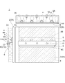
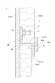
図1は、本発明の一実施形態にかかる吸音材の取付け構造を示した概略図であり、(a)は平面図、(b)は正面図、(c)が側面図となっている。図2は、本発明の一実施形態にかかる吸音材の断面を拡大して示した模式図である。図3は、本発明の一実施形態にかかるスタッドバー(スタッドボルト)を示した図である。図4〜図7は、本発明の一実施形態にかかる吸音材の取付け構造を拡大して示した断面図である。 FIG. 1 is a schematic view showing a sound absorbing material mounting structure according to an embodiment of the present invention, in which (a) is a plan view, (b) is a front view, and (c) is a side view. FIG. 2 is an enlarged schematic view showing a cross section of the sound absorbing material according to the embodiment of the present invention. FIG. 3 is a view showing a stud bar (stud bolt) according to an embodiment of the present invention. 4 to 7 are enlarged cross-sectional views showing a sound absorbing material mounting structure according to an embodiment of the present invention.
本発明の一実施形態にかかる吸音材の取付け構造1は、図1に示したように、壁面2に吸音材4を取付ける吸音材取付け構造である。そして、スタッドボルト6と、アングル部材8と、押え部10と、を備えている。
A sound absorbing
壁面2は、鉄製のスタッドバー6がスタッド溶接可能な材質からなり、例えば亜鉛メッキ鋼板からなる。後述する幾つかの実施形態では、壁面2は、可搬式容器100の内壁面を構成する内壁パネル2Aからなる。
The
吸音材4は、後述する騒音発生源からの騒音を吸音するための部材であり、例えばグラスウールやロックウールなどの繊維状の素材からなる。図2に示した実施形態では、吸音材4は、綿状のグラスウール4aの外表面をガラスクロス4bで包み込むことにより形成されている。なお、幾つかの実施形態では、吸音材4はガラスクロス4bを有していなくてもよい。
The
スタッドバー6は、図3の(a)に示すように、棒状の軸部6Aと、軸部6Aの一端部に設けられた、軸部6Aよりも大径に形成された頭部6Bと、からなる。頭部6Bの先端面6bは中心部から外周縁に向かって軸部6A側に傾斜するテーパ形状を有するとともに、その中心位置には凸部6cが形成されている。そして、図3の(b)に示すように、凸部6cが壁面2に形成されているポンチ穴2aの挿入された状態で、頭部6Bが壁面2に対してスタッド溶接により固定される。スタッド溶接によって先端面6bが溶融して平滑化することで、先端面6bが壁面2に対して面着される。また、図示した実施形態では、スタッドバー6は、壁面2の幅方向において、間隔をあけて複数配置されている。
As shown in FIG. 3A, the
アングル部材8は、図4〜図7に示したように、スタッドバー6の軸部6Aが挿通される貫通穴8aを有する。そして、貫通穴8aにスタッドバー6が挿通された状態でスタッドバー6と結合されることで、壁面2に固定されるようになっている。
As shown in FIGS. 4 to 7, the
押え部10は、図1及び図4〜図7に示したように、上述したアングル部材8に設けられており、壁面2との間で吸音材4を挟持するように構成されている。
As shown in FIGS. 1 and 4 to 7, the
このような本発明の一実施形態にかかる吸音材の取付け構造1によれば、壁面2にスタッド溶接されたスタッドバー6にアングル部材8が結合されることで、アングル部材8が壁面2に固定される。そして、この壁面2に固定されたアングル部材8に設けられた押え部10と壁面2との間に吸音材4が挟持されることで、吸音材4が壁面2に取付けられる。
According to the sound
したがって、従来の取付け方法と比べて、アングル部材8をその全長に亘って壁面2に溶接する必要がないことから、溶接に要していた時間を大幅に短縮することが出来る。また、スタッド溶接を採用したことにより、従来の取付け方法と比べて、溶接による熱影響を最小限に抑えることができる。このため、溶接による焼け跡の除去や、残留ひずみの除去を行う必要がなく、作業時間を更に低減することが出来る。また、スタッド溶接を採用したことにより、従来の取付け方法のように溶接資格といった組立工員の制限がなくなる。
Therefore, compared with the conventional attachment method, since it is not necessary to weld the
これらにより、従来の取付け方法と比べて、簡単かつ迅速な方法で壁面2に吸音材4を取付けることが出来るようになっている。
Thus, it is possible to attach the
しかも、壁面2とアングル部材8とが直接溶接されているのではなく、壁面2にスタッド溶接されたスタッドバー6に対してアングル部材8が固定される。このため、従来の取付け方法と比べて、アングル部材8の取り外しが容易となり、吸音材4を交換する際の作業性を大幅に向上させることが出来る。
In addition, the
上述した吸音材の取付け構造1を後述する可搬式容器100に適用する場合において、可搬式容器100の使用場所に応じて吸音材4の種類を異なるものに変更する場合がある。例えば、可搬式容器100を騒音規制がより厳しい場所で使用する場合は、吸音材4をより高性能なものに変更する場合がある。上述した実施形態によれば、このような場合であっても、吸音材4を交換する際の作業が容易である。
When the above-described sound absorbing
幾つかの実施形態では、図1及び図4〜図7に示したように、上述したアングル部材8は、壁面2に対して交差する方向に延在するウェブ部8Aと、貫通穴8aが形成された、ウェブ部8Aの一端側に接続する基端側フランジ部8Bと、を含む。そして、押え部10は、ウェブ部8Aの他端側に設けられた、壁面2に対して平行な方向に延在する板状部材からなる。
In some embodiments, as shown in FIGS. 1 and 4 to 7, the
図示した実施形態では、ウェブ部8Aは、壁面2に対して垂直な方向に延在している。すなわち、押え部10は、ウェブ部8Aに対して垂直な方向に延在している。また、基端側フランジ部8Bは、壁面2に対して平行な方向に延在している。これにより、壁面2と基端側フランジ部8Bとが面接触するため、アングル部材8が壁面2に対して強固に固定される。
In the illustrated embodiment, the
また、図示した実施形態では、スタッドバー8は、基端側フランジ部8Bの裏面(壁面2と反対側の面)から壁面2から離れる方向に突出している。そして、その先端部が、吸音材4の内部にめり込むように(吸音材4の表面を凹ますように)して、吸音材4と当接している。これにより、吸音材4のズレや脱落などを効果的に防止することができる。
Further, in the illustrated embodiment, the
このような実施形態によれば、上述したアングル部材8は、壁面2に対して交差する方向に延在するウェブ部8Aと、貫通穴8aが形成された、ウェブ部8Aの一端側に接続する基端側フランジ部8Bと、を含む。このようなアングル部材8としては、例えば、H形鋼、I形鋼、L形鋼、Z形鋼、C形(溝形)鋼などの一般に流通する各種のアングル部材8を使用することが出来る。
According to such an embodiment, the
幾つかの実施形態では、図5および図6に示したように、上述した押え部10は、アングル部材8と一体に形成された、ウェブ部8Aの他端側に接続する先端側フランジ部8Cからなる。
In some embodiments, as shown in FIGS. 5 and 6, the above-described
図5に示した実施形態では、先端側フランジ部8Cは、基端側フランジ部8Bが延在する方向と反対方向に延在している。そして、アングル部材8は、断面Z形状に形成されている。このような断面Z形状からなるアングル部材8によれば、基端側フランジ部8Bと先端側フランジ部8Cとが、互いに反対方向に延在しているため、1つのアングル部材8によって、隣接する2つの吸音材4A、4Bを壁面2に対して取付けることができる。
In the embodiment shown in FIG. 5, the distal end
一方、図6に示した実施形態では、先端側フランジ部8Cは、基端側フランジ部8Bが延在する方向と反対方向に延在している。そして、アングル部材8は、断面C形状(溝形状)に形成されている。このような断面C形状からなるアングル部材8によれば、基端側フランジ部8Bと先端側フランジ部8Cとが、互いに同じ方向に延在しているため、これら基端側フランジ部8Bと先端側フランジ部8Cとの間に吸音材4を保持することにより、吸音材4のズレや脱落などが生じ難くなっている。
On the other hand, in the embodiment shown in FIG. 6, the distal end
このような実施形態によれば、押え部10として、アングル部材8と一体に形成された、ウェブ部8Aの他端側に接続する先端側フランジ部8Cを採用することで、押え部10をアングル部材8とは別体の部材から構成する場合と比べて、部品点数を少なくすることができる。
According to such an embodiment, by adopting the front end
幾つかの実施形態では、図7に示したように、上述した押え部10は、アングル部材8と別体に形成された、ウェブ部8Aの他端側に固定された押え板11Bからなる。
In some embodiments, as shown in FIG. 7, the above-described
図示した実施形態では、アングル部材8は、ウェブ部8Aと、ウェブ部8Aの一端側から延在する基端側フランジ部8Bと、を有する断面L形状からなる。
In the illustrated embodiment, the
また、図示した実施形態では、押え板11Bは、壁面2に対して平行な方向に延在する延在部11Baと、延在部11Baの一端側から延在部11Baに対して直交する方向に延在する固定部11Bbと、を有する板状のL字状部材からなる。延在部11Baは、基端側フランジ部8Bと同じ方向に延在している。そして、固定部11Bbがウェブ部8Aの他端側に固定されている。
Further, in the illustrated embodiment, the
このような実施形態によれば、上述した押え部10として、アングル部材8と別体に形成された、ウェブ部8Aの他端側に取付けられた押え板11Bを採用することで、押え板11Bと壁面2との間で吸音材4を挟持することができる。また、押え板11Bが取付けられていない状態のアングル部材8をスタッドバー6に固定することで、アングル部材8をスタッドバー6に固定する際の作業性が向上する。また、アングル部材8に吸音材4が取付けられた状態で、押え板11Bをアングル部材8に固定することで、吸音材4に厚みや大きさに柔軟に対応可能な取付け構造とすることができる。
According to such an embodiment, the
幾つかの実施形態では、図4に示したように、上述した押え部10は、アングル部材8と一体に形成された、ウェブ部8Aの他端側に接続する先端側フランジ部8Cと、アングル部材8と別体に形成された、先端側フランジ部8Cに固定された押え板11Aと、からなる。
In some embodiments, as shown in FIG. 4, the
図示した実施形態では、先端側フランジ部8Cは、基端側フランジ部8Bが延在する方向と反対方向に延在している。そして、アングル部材8は、断面Z形状に形成されている。
In the illustrated embodiment, the
また、図示した実施形態では、押え板11Aは、壁面2に対して平行な方向に延在する平板状部材からなる。押え板11Aは、先端側フランジ部8Cに固定されるとともに、先端側フランジ部8Cが延在する方向とは反対方向に延在している。
In the illustrated embodiment, the presser plate 11 </ b> A is made of a flat plate member extending in a direction parallel to the
このような実施形態によれば、押え部10として、アングル部材8と一体に形成された、ウェブ部8Aの他端側に接続する先端側フランジ部8C、およびアングル部材8と別体に形成された、先端側フランジ部8Cに固定された押え板11A、の両方を採用することで、先端側フランジ部8Cと押え板11Aとの両方によって、壁面2との間で吸音材4を挟持することができる。
According to such an embodiment, the
また、押え板11Aが、先端側フランジ部8Cが延在する方向とは反対方向に延在しているため、先端側フランジ部8Cと押え板11Aの両方によって、アングル部材8を挟んで隣接する2つの吸音材4A、4Bをまとめて保持できるようになっている。
Further, since the
幾つかの実施形態では、図4および図5に示したように、上述した基端側フランジ部8Bは、ウェブ部8Aから一方側に向かって延在する。そして、先端側フランジ部8Cは、ウェブ部8Aから、一方側とは反対側である他方側に向かって延在する。
In some embodiments, as shown in FIGS. 4 and 5, the above-described proximal
このような実施形態によれば、アングル部材8の基端側フランジ部8Bと先端側フランジ部8Cとが互いに逆向きにウェブ部8Aから延在している。これにより、スタッドバー6の延在方向の延長線上に先端側フランジ部8Cが位置しないため、アングル部材8をスタッドバー6に固定する際に、先端側フランジ部8Cが固定作業の障害とはならない。よって、アングル部材8をスタッドバー6に固定する際の作業性が優れている。
According to such an embodiment, the proximal end
幾つかの実施形態では、図7に示したように、上述した押え板11Bは、ウェブ部8Aに対して垂直な方向に挿通されたリベット12によって、ウェブ部8Aに取付けられる。そして、リベット12の先端は、吸音材4に当接する。
In some embodiments, as shown in FIG. 7, the above-described
図示した実施形態では、ウェブ部8Aの先端側に形成されている貫通孔8Ah、および押え板11Bの固定部11Bbに形成されている貫通孔11Bbhにリベット12が挿通され、その頭部が加締められることで、押え板11Bがウェブ部8Aに固定されている。そして、リベット12の先端部が、吸音材4の内部にめり込むように(吸音材4の表面を凹ますように)して、吸音材4と当接している。
In the illustrated embodiment, the
なお、押え板11Aを頻繁に取り外す必要があるような部位においては、リベット12に替えてビスを用いてもよい。
It should be noted that a screw may be used in place of the
このような実施形態によれば、リベット12によって、押え板11Bをアングル部材8のウェブ部8Aに容易に固定することができるとともに、このリベット12の先端を吸音材4に当接させることで、吸音材4のズレや脱落などを効果的に防止することができる。
According to such an embodiment, the holding
幾つかの実施形態では、図4に示したように、上述した押え板11Aは、先端側フランジ部8Cに対して垂直な方向に挿通されたリベット12によって、先端側フランジ部8Cに固定される。そして、リベット12の先端は、吸音材4に当接する。
In some embodiments, as shown in FIG. 4, the above-described
図示した実施形態では、先端側フランジ部8Cに形成されている貫通孔8Ch、および押え板11Aに形成されている貫通孔11Ahにリベット12が挿通され、その頭部が加締められることで、押え板11Aが先端側フランジ部8Cに固定されている。そして、リベット12の先端部が、吸音材4の内部にめり込むように(吸音材4の表面を凹ますように)して、吸音材4と当接している。
In the illustrated embodiment, the
このような実施形態によれば、リベット12によって、押え板11Aをアングル部材8の先端側フランジ部8Cに容易に固定することができるとともに、このリベット12の先端を吸音材4に当接させることで、吸音材4のズレや脱落などを効果的に防止することができる。
According to such an embodiment, the holding
幾つかの実施形態では、図3に示したように、上述したスタッドバー6は、軸部6Aにネジ溝6aが形成されたスタッドボルト6からなる。図4〜図7に示したように、アングル部材8は、スタッドボルト6に螺着されたナット7によって、スタッドボルト6に結合される。そして、ネジ溝6aのピッチtは、JIS
B 0207(1999)に規定される細目ネジのピッチと同じか、それ未満である。
In some embodiments, as shown in FIG. 3, the above-described
It is the same as or less than the pitch of the fine thread defined in B 0207 (1999).
このような実施形態によれば、スタッドボルト6とアングル部材8とをボルト締結によって簡単に結合することができる。また、ネジ溝6aのピッチtを細目ネジのピッチと同じか、それ未満とすることで、スタッドボルト6とアングル部材8とを強固に結合することができ、振動などによって締結部が緩んでしまうことを防ぐことができる。
According to such an embodiment, the
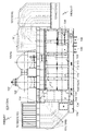
図8は、本発明の一実施形態にかかる可搬式容器を示した側面図である。図9は、本発明の一実施形態にかかる可搬式容器を示した上面図である。 FIG. 8 is a side view showing a portable container according to an embodiment of the present invention. FIG. 9 is a top view showing a portable container according to an embodiment of the present invention.
本発明の一実施形態にかかる可搬式容器は、例えばトレーラなどの輸送機器によって搬送可能な可搬式容器100である。そして、可搬式容器100は、騒音発生源102を収容するとともに、可搬式容器100の内壁パネル2Aには、上述した実施形態にかかる吸音材の取付け構造1によって吸音材4が取付けられている。
A portable container according to an embodiment of the present invention is a
図示した実施形態では、可搬式容器100は、規格サイズのコンテナ本体100Ab(例えば40fコンテナ)に、吸気側フード部101Aおよび排気側フード部101Bが結合されることで構成されている。
In the illustrated embodiment, the
なお、図示した実施形態において、符号102は騒音発生源(エンジン102A)、103は発電機、104はラジエータ、105はマフラ、106はバッテリ、107は排気出口、108は高圧用配線口、109は制御用配線口、110は冷却水ドレン、111は潤滑油ドレン、112は燃料入口、113は燃料戻り口、114は油気出口、115はスラッジ排出口、116は雨水ドレン、である。
In the illustrated embodiment,
このような実施形態によれば、輸送機器によって搬送可能な可搬式容器100において、その内壁パネル2Aに吸音材4を取付けることで、可搬式容器100の内部に収容される騒音発生源102からの騒音が外部に漏れ伝わるのを防止することができる。
According to such an embodiment, in the
幾つかの実施形態では、図8および図9に示したように、上述した可搬式容器100(100A)は、発電機103を収容する。そして、騒音発生源102は、発電機103を駆動するためのエンジン102Aからなる。
In some embodiments, as shown in FIGS. 8 and 9, the portable container 100 (100 </ b> A) described above houses the
なお、図示しないが、騒音発生源102としては、エンジン102Aに替えて、例えば蒸気タービン、ガスタービン、燃料電池などを、発電機103を駆動するための動力発生源として用いてもよい。
Although not shown, as the
このような実施形態によれば、可搬式容器100が、発電機103や、発電機103を駆動するための動力発生源などの発電設備が収容された可搬式発電ユニットの可搬式容器100Aとして構成される。このように、本発明の可搬式容器100は、可搬式発電ユニットの可搬式容器100Aとしても、好適に用いられるものである。
According to such an embodiment, the
また、可搬式容器100は、想定される各種の荷重に耐え得るような強度を有している必要がある。特に可搬式容器100は、例えばトレーラなどの輸送機器によって搬送されるため、輸送時における振動荷重などに対して耐え得るような強度を有している必要がある。
この点、上述した実施形態によれば、スタッドバー6を介して内壁パネル2Aに固定されるアングル部材8が補強材としての役割を果たすため、内壁パネル2Aの剛性を高めることができる。
Moreover, the
In this regard, according to the above-described embodiment, the
なお、アングル部材8が内壁パネル2Aの補強材としての役割を果たすためには、アングル部材8が所定以上の長さで内壁パネル2Aに固定されている必要があり、好ましくは、アングル部材8が、内壁パネル2Aの一端縁から他端縁に亘って、内壁パネル2Aの全幅(全高)に亘って延在しているとよい。
In order for the
図10は、本発明の一実施形態にかかる可搬式容器を示した概略平面図である。
幾つかの実施形態では、図10に示したように、上述した可搬式容器100(100B)は、動力発生源(不図示)から排出される排熱を回収するための排熱回収装置120を収容する。そして、騒音発生源は、排熱回収装置120からなる。
FIG. 10 is a schematic plan view showing a portable container according to an embodiment of the present invention.
In some embodiments, as shown in FIG. 10, the portable container 100 (100B) described above includes an exhaust
なお、排熱回収装置120によって、上述した可搬式発電ユニットの可搬式容器100Aに収容される動力発生源から排出される排熱を回収するように構成することで、すなわち、上述した可搬式発電ユニットの可搬式容器100Aと併用することで、コジェネレーション(熱電併給)にも対応することが出来るようになっている。
The exhaust
図示した実施形態では、可搬式容器100は、規格サイズのコンテナ本体100Bb(例えば20fコンテナ)からなる。また、排熱回収装置120は、排熱回収ボイラ120Aからなる。排熱回収ボイラ120Aは、例えば上述したエンジン102Aなどの可搬式容器100の外部に配置されている動力発生源から、排ガス導入口120aを介して排ガスを導入する。そして、導入した排ガスの排熱から蒸気を生成するように構成されている。
In the illustrated embodiment, the
また、図示した実施形態では、可搬式容器100には、熱交換器122、マフラ装置124、連結管126、及びダンパー128などの各種の周辺機器類が収容されている。
In the illustrated embodiment, the
このような実施形態によれば、可搬式容器100は、排熱回収装置120を収容し、騒音発生源は、動力発生源から排出される排熱を回収するための排熱回収装置120(例えば排熱回収ボイラ120A)からなる。すなわち、本実施形態の可搬式容器100は、排熱回収装置120などの周辺機器類が収容された可搬式熱回収ユニットの可搬式容器100Bとして構成される。このように、本発明の可搬式容器100は、可搬式熱回収ユニットの可搬式容器100Bとしても、好適に用いられるものである。
According to such an embodiment, the
幾つかの実施形態では、図8に示したように、上述した可搬式容器100は、鉛直方向(重力の作用する方向)に開口する通気口101Oを有するフード部101を有する。そして、アングル部材8は、少なくともアングル部材8の一部がフード部101において、鉛直方向に沿って延在する。
In some embodiments, as shown in FIG. 8, the
図示した実施形態では、可搬式容器100は、吸気側フード部101Aおよび排気側フード部101Bの2つのフード部101を有している。そして、吸気側フード部101Aでは、その吸気側通気口101AOは鉛直下方に向けて開口している。吸気側通気口101AOから鉛直上方に向かって流入した空気は、吸気側フード部101Aの内部においてその方向が転向され、鉛直下方に向かってコンテナ本体100Abに流入する。そして、コンテナ本体100Abの内部を水平方向に沿って流れていく。
In the illustrated embodiment, the
一方、排気側フード部101Bでは、その排気側通気口101BOは鉛直上方に向けて開口している。そして、これら吸気側フード部101Aおよび排気側フード部101Bの内部には、その内壁パネル2Aに固定されてアングル部材8は鉛直方向に沿って延在している。コンテナ本体100Abの内部を水平方向に沿って流れた空気は、排気側通気口101BOから鉛直上方に向かって流出する。
On the other hand, in the exhaust
エンジン102Aなどの動力発生源や、排熱回収ボイラ120Aなどの排熱回収装置120を収容する可搬式容器100においては、それら機器を冷却するための冷却空気を外部から導入する必要がある。
よって、このような実施形態によれば、水平方向ではなく鉛直方向に通気口101Oを開口させることで、通気口101Oから漏れ伝わる騒音が可搬式容器100の周囲に響くのを防止している。また、鉛直方向に開口する通気口101Oを有するフード部101の内部では、空気は鉛直方向に沿って流れることとなる。よって、空気の流れる鉛直方向に沿ってアングル部材8を延在させることで、アングル部材8が空気流の流れ方向に沿って配置されることとなり、アングル部材8が空気流に対して抵抗になることを抑制することができる。
In the
Therefore, according to such an embodiment, by opening the vent 101O in the vertical direction instead of the horizontal direction, it is possible to prevent noise transmitted from the vent 101O from reverberating around the
図11および図12は、本発明の一実施形態にかかる吸音材の取付け方法を示したフロー図である。
本発明の一実施形態にかかる吸音材の取付け方法は、壁面2に吸音材4を取付ける吸音材取付け方法である。そして、図11に示したように、壁面2にスタッドバー6をスタッド溶接するステップ(スタッドバー溶接ステップS2)と、スタッドバー6が挿通される貫通穴8aを有するアングル部材8を、貫通穴8aにスタッドバー6が挿通された状態でスタッドバー6と結合し、壁面2に固定するステップ(アングル剤固定ステップS3)と、アングル部材8に設けられる押え部10と、壁面2との間で、吸音材4を挟持するステップ(吸音材取付けステップS4)と、を備えている。
FIG. 11 and FIG. 12 are flowcharts showing a method for attaching a sound absorbing material according to an embodiment of the present invention.
The method for attaching the sound absorbing material according to the embodiment of the present invention is a sound absorbing material attaching method for attaching the
また、図12に示した実施形態は、図4および図7に示したように、押え部10がアングル部材8とは別体の押え板11A、11Bからなるものに対応するフロー図である。そして、上述した吸音材取付けステップS4は、壁面2に固定されているアングル部材8に対して吸音材4を位置決めする吸音材位置決めステップ(S41)と、吸音材4が位置決めされた状態で、アングル部材8に押え板11A、11Bを固定することで、吸音材4を挟持するステップ(押え板固定ステップS42)を含んでいる。
Further, the embodiment shown in FIG. 12 is a flowchart corresponding to a structure in which the
このような実施形態によれば、上述した吸音材の取付け構造1と同様に、簡単かつ迅速な方法で壁面2に吸音材4を取付けることが出来る。
According to such an embodiment, the
幾つかの実施形態では、図11に示しように、上述した溶接ステップS1の前に、壁面2におけるスタッドバー6が溶接される位置に、予めポンチ穴2aを加工するステップをさらに備える。
In some embodiments, as shown in FIG. 11, the
ポンチ穴2aは、例えば、図3の(b)に示したように、スタッドバー6の頭部6Bに形成されている凸部6cの高さと同じ程度の深さhを有している。このようなポンチ穴は、例えば、タレッドポンチプレスなどのプレス機械によって、壁面2(内壁パネル2A)に対して形成することができる。
For example, as shown in FIG. 3B, the
このような実施形態によれば、壁面2におけるスタッドバー6が溶接される位置に、予めポンチ穴2aが加工される。このため、スタッドバー6をスタッド溶接する際に、その位置出しおよび位置決めが容易となる。
According to such an embodiment, the
以上、本発明の好ましい形態について説明したが、本発明は上記の形態に限定されるものではなく、本発明の目的を逸脱しない範囲での種々の変更が可能である。 As mentioned above, although the preferable form of this invention was demonstrated, this invention is not limited to said form, A various change in the range which does not deviate from the objective of this invention is possible.
1 吸音材の取付け構造
2 壁面
2A 内壁パネル
2a ポンチ穴
4,4A,4B 吸音材
4a グラスウール
4b ガラスクロス
6 スタッドバー(スタッドボルト)
6A 軸部
6B 頭部
6a ネジ溝
6b 先端面
6c 凸部
7 ナット
8 アングル部材
8A ウェブ部
8Ah 貫通孔
8B 基端側フランジ部
8C 先端側フランジ部
8Ch 貫通孔
10 押え部
11A 押え板
11A 押え板
11Ah 貫通孔
11B 押え板
11Ba 延在部
11Bb 固定部
11Bbh 貫通孔
12 リベット
100,100A,100B 可搬式容器
100Ab,100Bb コンテナ本体
101 フード部
101A 吸気側フード部
101B 排気側フード部
101O 通気口
101AO 吸気側通気口
101BO 排気側通気口
102 騒音発生源
102A エンジン
103 発電機
120 排熱回収装置
120A 排熱回収ボイラ
120a 排ガス導入口
122 熱交換器
124 マフラ装置
126 連結管
128 ダンパー
1 Sound absorbing
6A
Claims (15)
前記壁面にスタッド溶接されたスタッドバーと、
前記スタッドバーが挿通される貫通穴を有するアングル部材であって、前記貫通穴に前記スタッドバーが挿通された状態で前記スタッドバーと結合されることで、前記壁面に固定されるアングル部材と、
前記アングル部材に設けられ、前記壁面との間で前記吸音材を挟持するための押え部と、を備える吸音材の取付け構造。 A sound absorbing material mounting structure for attaching a sound absorbing material to a wall surface,
A stud bar stud-welded to the wall surface;
An angle member having a through hole through which the stud bar is inserted, and an angle member fixed to the wall surface by being coupled to the stud bar in a state where the stud bar is inserted into the through hole;
A sound absorbing material mounting structure comprising: a pressing portion provided on the angle member and sandwiching the sound absorbing material with the wall surface.
前記壁面に対して交差する方向に延在するウェブ部と、
前記貫通穴が形成された、前記ウェブ部の一端側に接続する基端側フランジ部と、を含み、
前記押え部は、前記ウェブ部の他端側に設けられた、前記壁面に対して平行な方向に延在する板状部材からなる、請求項1に記載の吸音材の取付け構造。 The angle member is
A web portion extending in a direction intersecting the wall surface;
A proximal flange portion formed on the through hole and connected to one end side of the web portion;
2. The sound absorbing material mounting structure according to claim 1, wherein the pressing portion is formed of a plate-like member provided on the other end side of the web portion and extending in a direction parallel to the wall surface.
前記アングル部材と一体に形成された、前記ウェブ部の他端側に接続する先端側フランジ部と、
前記アングル部材と別体に形成された、前記先端側フランジ部に固定された押え板と、からなる、請求項2に記載の吸音材の取付け構造。 The presser part is
A flange portion formed integrally with the angle member and connected to the other end side of the web portion; and
The sound absorbing material mounting structure according to claim 2, comprising: a presser plate formed separately from the angle member and fixed to the front end side flange portion.
前記先端側フランジ部は、前記ウェブ部から、前記一方側とは反対側である他方側に向かって延在する、請求項3または5に記載の吸音材の取付け構造。 The proximal end flange portion extends from the web portion toward one side,
The sound absorbing material mounting structure according to claim 3 or 5, wherein the front end flange portion extends from the web portion toward the other side opposite to the one side.
前記リベットまたは前記ビスの先端は、前記吸音材に当接する、請求項4に記載の吸音材の取付け構造。 The presser plate is fixed to the web part by rivets or screws inserted in a direction perpendicular to the web part,
The sound absorbing material mounting structure according to claim 4, wherein a tip of the rivet or the screw comes into contact with the sound absorbing material.
前記リベットまたは前記ビスの先端は、前記吸音材に当接する、請求項5に記載の吸音材の取付け構造。 The presser plate is fixed to the front end side flange portion by rivets or screws inserted in a direction perpendicular to the front end side flange portion,
The sound absorbing material mounting structure according to claim 5, wherein a tip of the rivet or the screw abuts on the sound absorbing material.
前記アングル部材は、前記スタッドボルトに螺着されたナットによって、前記スタッドボルトに結合され、
前記ネジ溝のピッチは、JIS B 0207(1999)に規定される細目ネジのピッチと同じか、それ未満である、請求項1から8の何れか1項に記載の吸音材の取付け構造。 The stud bar is composed of a stud bolt in which a thread groove is formed in a shaft portion,
The angle member is coupled to the stud bolt by a nut screwed to the stud bolt,
The sound absorbing material mounting structure according to any one of claims 1 to 8, wherein a pitch of the thread groove is equal to or less than a pitch of a fine screw defined in JIS B 0207 (1999).
前記可搬式容器は、騒音発生源を収容し、
前記可搬式容器の内壁パネルには、請求項1から9の何れか1項に記載の吸音材の取付け構造によって前記吸音材が取付けられている、可搬式容器。 A portable container that can be transported by a transport device,
The portable container contains a noise source,
The portable container by which the said sound-absorbing material is attached to the inner wall panel of the said portable container by the sound-absorbing-material attachment structure of any one of Claim 1 to 9.
前記騒音発生源は、前記発電機を駆動するための動力発生源からなる、請求項10に記載の可搬式容器。 The portable container contains a generator,
The portable container according to claim 10, wherein the noise generation source is a power generation source for driving the generator.
前記騒音発生源は、前記排熱回収装置からなる、請求項10に記載の可搬式容器。 The portable container accommodates an exhaust heat recovery device for recovering exhaust heat exhausted from a power generation source,
The portable container according to claim 10, wherein the noise generation source includes the exhaust heat recovery device.
前記アングル部材は、前記フード部において、少なくとも前記アングル部材の一部が前記鉛直方向に沿って延在する、請求項11または12の何れか1項に記載の可搬式容器。 The portable container has a hood portion having a vent opening in a vertical direction,
13. The portable container according to claim 11, wherein at least a part of the angle member extends along the vertical direction in the hood portion.
前記壁面にスタッドバーをスタッド溶接する溶接ステップと、
前記スタッドバーが挿通される貫通穴を有するアングル部材を、前記貫通穴に前記スタッドバーが挿通された状態で前記スタッドバーと結合し、前記壁面に固定するステップと、
前記アングル部材に設けられる押え部と、前記壁面との間で、前記吸音材を挟持する吸音材取付けステップと、を備える吸音材の取付け方法。 A sound absorbing material mounting method for attaching a sound absorbing material to a wall surface,
Welding step for stud welding a stud bar to the wall surface;
An angle member having a through-hole through which the stud bar is inserted, and the stud bar is coupled to the stud bar in a state where the stud bar is inserted into the through-hole, and fixed to the wall surface;
A sound absorbing material mounting method, comprising: a sound absorbing material mounting step for sandwiching the sound absorbing material between a pressing portion provided in the angle member and the wall surface.
Priority Applications (1)
| Application Number | Priority Date | Filing Date | Title |
|---|---|---|---|
| JP2016077303A JP6690981B2 (en) | 2016-04-07 | 2016-04-07 | Sound absorbing material mounting structure, sound absorbing material mounting method, and portable container |
Applications Claiming Priority (1)
| Application Number | Priority Date | Filing Date | Title |
|---|---|---|---|
| JP2016077303A JP6690981B2 (en) | 2016-04-07 | 2016-04-07 | Sound absorbing material mounting structure, sound absorbing material mounting method, and portable container |
Publications (2)
| Publication Number | Publication Date |
|---|---|
| JP2017187677A true JP2017187677A (en) | 2017-10-12 |
| JP6690981B2 JP6690981B2 (en) | 2020-04-28 |
Family
ID=60044891
Family Applications (1)
| Application Number | Title | Priority Date | Filing Date |
|---|---|---|---|
| JP2016077303A Active JP6690981B2 (en) | 2016-04-07 | 2016-04-07 | Sound absorbing material mounting structure, sound absorbing material mounting method, and portable container |
Country Status (1)
| Country | Link |
|---|---|
| JP (1) | JP6690981B2 (en) |
Citations (6)
| Publication number | Priority date | Publication date | Assignee | Title |
|---|---|---|---|---|
| JPH0464122U (en) * | 1990-10-16 | 1992-06-01 | ||
| JP3067521U (en) * | 1999-09-17 | 2000-04-07 | Noise barrier | |
| JP2000282596A (en) * | 1999-03-29 | 2000-10-10 | Mitsubishi Heavy Ind Ltd | Ceramic sound absorption board panel structure |
| JP2003055919A (en) * | 2001-08-10 | 2003-02-26 | Odakyu Dentetsu Kk | How to build a noise barrier |
| JP2005240448A (en) * | 2004-02-27 | 2005-09-08 | Sumitomo Metal Steel Products Inc | Soundproofing device for bridge expansion and contraction |
| KR20130097027A (en) * | 2012-02-23 | 2013-09-02 | 예손기업주식회사 | A complex board panel for decoration panel of inner and outer wall and a construction method thereof |
-
2016
- 2016-04-07 JP JP2016077303A patent/JP6690981B2/en active Active
Patent Citations (6)
| Publication number | Priority date | Publication date | Assignee | Title |
|---|---|---|---|---|
| JPH0464122U (en) * | 1990-10-16 | 1992-06-01 | ||
| JP2000282596A (en) * | 1999-03-29 | 2000-10-10 | Mitsubishi Heavy Ind Ltd | Ceramic sound absorption board panel structure |
| JP3067521U (en) * | 1999-09-17 | 2000-04-07 | Noise barrier | |
| JP2003055919A (en) * | 2001-08-10 | 2003-02-26 | Odakyu Dentetsu Kk | How to build a noise barrier |
| JP2005240448A (en) * | 2004-02-27 | 2005-09-08 | Sumitomo Metal Steel Products Inc | Soundproofing device for bridge expansion and contraction |
| KR20130097027A (en) * | 2012-02-23 | 2013-09-02 | 예손기업주식회사 | A complex board panel for decoration panel of inner and outer wall and a construction method thereof |
Also Published As
| Publication number | Publication date |
|---|---|
| JP6690981B2 (en) | 2020-04-28 |
Similar Documents
| Publication | Publication Date | Title |
|---|---|---|
| JP5113597B2 (en) | Corrugated steel shear wall | |
| US7017334B2 (en) | Compact fastening collar and stud for connecting walls of a nozzle liner and method associated therewith | |
| US6896042B2 (en) | Structure of pipe plate unit for heat exchangers and method of replacement for the pipe plate unit | |
| US6345927B1 (en) | Weld reinforcement | |
| US20150053299A1 (en) | Uncoupling element | |
| JP2017187677A (en) | Sound absorbing material mounting structure, sound absorbing material mounting method, and portable container | |
| CN205806756U (en) | A kind of bearing-type bellow-type expansion joint | |
| CN217442334U (en) | Heat exchanger with flow path short circuit reduction guide cylinder structure | |
| CN213828188U (en) | Novel protective cover for numerical control drilling machine | |
| JP2014159883A (en) | Steam condenser | |
| JP2007120927A (en) | Condenser and condenser assembly method | |
| AU2009271038B2 (en) | Sootblower with modular canopy | |
| JP2018192950A (en) | Wiring structure of cross member | |
| CN222760275U (en) | Combined fixing support of auxiliary radiator and oil cooler and mining dump truck | |
| JP4988622B2 (en) | Water heater | |
| CN220666488U (en) | A connecting component for steel structures | |
| CN220892295U (en) | Lining structure capable of freely expanding along design direction and waste heat boiler | |
| KR200411657Y1 (en) | Tube for heat exchanger | |
| CN221079618U (en) | Detachable muffler of noise elimination original paper | |
| CN223878084U (en) | Taillight board of vehicle and vehicle | |
| CN113501124B (en) | Ship structural air pipe with silencer, installation method of ship structural air pipe and ship | |
| KR102823852B1 (en) | Steam boiler liquid separator and method for manufacturing the same | |
| JP4760948B2 (en) | Combination steel sheet pile and steel sheet pile wall using the combination steel sheet pile | |
| CN109654715A (en) | A kind of nuclear power station Combined type muffler | |
| CN104514605B (en) | For the muffler shell in the exhaust system of vehicle |
Legal Events
| Date | Code | Title | Description |
|---|---|---|---|
| A711 | Notification of change in applicant |
Free format text: JAPANESE INTERMEDIATE CODE: A712 Effective date: 20180517 |
|
| A621 | Written request for application examination |
Free format text: JAPANESE INTERMEDIATE CODE: A621 Effective date: 20181115 |
|
| A977 | Report on retrieval |
Free format text: JAPANESE INTERMEDIATE CODE: A971007 Effective date: 20190906 |
|
| A131 | Notification of reasons for refusal |
Free format text: JAPANESE INTERMEDIATE CODE: A131 Effective date: 20190917 |
|
| A521 | Request for written amendment filed |
Free format text: JAPANESE INTERMEDIATE CODE: A523 Effective date: 20191112 |
|
| TRDD | Decision of grant or rejection written | ||
| A01 | Written decision to grant a patent or to grant a registration (utility model) |
Free format text: JAPANESE INTERMEDIATE CODE: A01 Effective date: 20200310 |
|
| A61 | First payment of annual fees (during grant procedure) |
Free format text: JAPANESE INTERMEDIATE CODE: A61 Effective date: 20200409 |
|
| R150 | Certificate of patent or registration of utility model |
Ref document number: 6690981 Country of ref document: JP Free format text: JAPANESE INTERMEDIATE CODE: R150 |
|
| R250 | Receipt of annual fees |
Free format text: JAPANESE INTERMEDIATE CODE: R250 |
|
| R250 | Receipt of annual fees |
Free format text: JAPANESE INTERMEDIATE CODE: R250 |
|
| R250 | Receipt of annual fees |
Free format text: JAPANESE INTERMEDIATE CODE: R250 |
|
| R250 | Receipt of annual fees |
Free format text: JAPANESE INTERMEDIATE CODE: R250 |