JP2017190105A - Vehicle front structure - Google Patents
Vehicle front structure Download PDFInfo
- Publication number
- JP2017190105A JP2017190105A JP2016082214A JP2016082214A JP2017190105A JP 2017190105 A JP2017190105 A JP 2017190105A JP 2016082214 A JP2016082214 A JP 2016082214A JP 2016082214 A JP2016082214 A JP 2016082214A JP 2017190105 A JP2017190105 A JP 2017190105A
- Authority
- JP
- Japan
- Prior art keywords
- water
- vehicle
- support member
- impervious
- water shielding
- Prior art date
- Legal status (The legal status is an assumption and is not a legal conclusion. Google has not performed a legal analysis and makes no representation as to the accuracy of the status listed.)
- Granted
Links
Images
Landscapes
- Body Structure For Vehicles (AREA)
- Cooling, Air Intake And Gas Exhaust, And Fuel Tank Arrangements In Propulsion Units (AREA)
Abstract
【課題】 吸気ダクトへの水の侵入を抑制するとともに、前方衝突時に歩行者が受ける反力を低く抑えることができる、車両の前部構造を提供する。【解決手段】 車両100の前部構造1は、エンジン供給用の空気を導入する吸気口10aを有する吸気ダクト10と、吸気ダクト10の吸気口10aよりも低所に設けられ、吸気口10aに向かう上向きの水の流れを遮る遮水部材21と、を備え、遮水部材21は、車両100の前方衝突時の衝突荷重によって、遮水部材21の車両後方側に予め設けられた干渉回避空間8を車両後方へ移動するように構成されている。【選択図】 図1PROBLEM TO BE SOLVED: To provide a front structure of a vehicle capable of suppressing the intrusion of water into an intake duct and suppressing a reaction force received by a pedestrian at the time of a frontal collision. SOLUTION: A front structure 1 of a vehicle 100 is provided at a position lower than an intake duct 10 having an intake port 10a for introducing air for supplying an engine and an intake port 10a of the intake duct 10, and is provided in the intake port 10a. A water-impervious member 21 that blocks the upward flow of water is provided, and the water-impervious member 21 is provided in advance in an interference avoidance space on the rear side of the vehicle due to a collision load at the time of a frontal collision of the vehicle 100. It is configured to move 8 to the rear of the vehicle. [Selection diagram] Fig. 1
Description
本発明は、車両の前部構造に関する。 The present invention relates to a front structure of a vehicle.
下記の特許文献1には、車両の前部構造の一例が開示されている。この前部構造を構成する遮水板は、エンジンルームにおいてバンパの開口部よりも高所に取付けられている。この遮水板は、車両が冠水路などを走行したときにバンパの開口部からエンジンルームに入り込んで上向きに流れた水が吸気ダクトに侵入するのを防ぐためのものである。また、この遮水板は、バンパと放熱装置(コンデンサ、補助ファン等からなる装置)との前後間隔を塞ぐように車両前後方向に延在している。
ところで、車両の前側に歩行者が衝突した場合、歩行者が車両から反力を受ける。この反力が過大になると歩行者が受ける衝撃も大きくなる。そこで、車両の前部構造を設計する際には、歩行者の保護を図るために、衝突した歩行者が車両から受ける反力を極力小さく抑える点に留意する必要がある。 By the way, when a pedestrian collides with the front side of the vehicle, the pedestrian receives a reaction force from the vehicle. If this reaction force becomes excessive, the impact on the pedestrian will increase. Therefore, when designing the front structure of the vehicle, it is necessary to keep in mind that the reaction force that the colliding pedestrian receives from the vehicle is minimized to protect the pedestrian.
しかしながら、歩行者の保護を図るという観点に基づいた場合、上記の特許文献1に開示の前部構造は、以下のような問題点を抱えている。
即ち、この前部構造を構成する遮水板は、エンジンルームにおいて歩行者の脚部(典型的には、歩行者の脚部のうち膝や脛の周辺部位)に相当する高さを車両前後方向に延在し、且つバンパと放熱装置との間に介装されている。このため、この遮水板は、車両の前方衝突時の衝突荷重によって車両後方へ移動しようとしても、この移動が放熱装置によって制限される。従って、車両の前方衝突時の衝突荷重に対して遮水板が抵抗になって反力が生じるため、歩行者の脚部が車両から受ける反力(衝撃)が増大するという問題が生じ得る。
However, when based on the viewpoint of protecting pedestrians, the front structure disclosed in
That is, the water shielding plate constituting the front structure has a height corresponding to the pedestrian's legs (typically, the pedestrian's legs around the knees and shins) in the engine room. It extends in the direction and is interposed between the bumper and the heat dissipation device. For this reason, even if this water shielding board tries to move to the rear of the vehicle due to a collision load at the time of a frontal collision of the vehicle, this movement is limited by the heat dissipation device. Therefore, since the water shielding plate becomes a resistance against a collision load at the time of a frontal collision of the vehicle and a reaction force is generated, there may be a problem that a reaction force (impact) that the pedestrian's leg receives from the vehicle increases.
本発明は、かかる課題に鑑みてなされたものであり、吸気ダクトへの水の侵入を抑制するとともに、前方衝突時に歩行者が受ける反力を低く抑えることができる、車両の前部構造を提供しようとするものである。 The present invention has been made in view of such a problem, and provides a vehicle front structure that can suppress the intrusion of water into an intake duct and can reduce the reaction force that a pedestrian receives during a frontal collision. It is something to try.
本発明の一態様は、
エンジン供給用の空気を導入する吸気口を有する吸気ダクトと、
上記吸気ダクトの上記吸気口よりも低所に設けられ、上記吸気口に向かう上向きの水の流れを遮る遮水部材と、
を備え、
上記遮水部材は、車両の前方衝突時の衝突荷重によって、該遮水部材の車両後方側に予め設けられた干渉回避空間を車両後方へ移動するように構成されている、車両の前部構造にある。
One embodiment of the present invention provides:
An intake duct having an intake port for introducing air for engine supply;
A water-impervious member that is provided at a lower position than the intake port of the intake duct and blocks an upward flow of water toward the intake port;
With
The front structure of the vehicle is configured such that the water shielding member is configured to move to an interference avoidance space provided in advance on the vehicle rear side of the water shielding member due to a collision load at the time of a frontal collision of the vehicle. It is in.
上記の車両の前部構造において、遮水部材は、吸気ダクトの吸気口に向かう上向きの水の流れを遮ることによって吸気ダクトへの水の侵入を抑制することができる。一方で、車両の前方衝突時に衝突荷重を受けた遮水部材は、干渉回避空間を車両後方へ移動する。このため、車両の前方衝突時の衝突荷重に対して遮水部材が抵抗になるのを回避できる。 In the vehicle front structure described above, the water-impervious member can prevent water from entering the intake duct by blocking upward water flow toward the intake port of the intake duct. On the other hand, the water-impervious member that has received a collision load at the time of a frontal collision of the vehicle moves rearward in the interference avoidance space. For this reason, it can avoid that a water shielding member becomes resistance with respect to the collision load at the time of the front collision of a vehicle.
上記の態様によれば、吸気ダクトへの水の侵入を抑制するとともに、前方衝突時に歩行者が車両から受ける反力を低く抑えることが可能になる。即ち、遮水部材による遮水性能と歩行者保護性能との両立が可能になる。 According to the above aspect, it is possible to suppress the intrusion of water into the intake duct and to reduce the reaction force that the pedestrian receives from the vehicle at the time of a forward collision. That is, it is possible to achieve both the water shielding performance by the water shielding member and the pedestrian protection performance.
上記の車両の前部構造において、上記遮水部材を上記干渉回避空間に向けてスライド可能に支持する支持部材を備えるのが好ましい。これにより、遮水部材を支持部材によって干渉回避空間に確実に移動させることができる。 The vehicle front structure preferably includes a support member that slidably supports the water shielding member toward the interference avoidance space. Thereby, the water-impervious member can be reliably moved to the interference avoidance space by the support member.
上記の車両の前部構造において、上記遮水部材は、車体のバンパ側から上記干渉回避空間に向けて車両後方へ延出した後方延出部を有し、上記支持部材は、車体の上記吸気ダクト側から車両前方へ延出した前方延出部を有し、上記前方延出部が上記遮水部材の上記後方延出部と車両上下方向について重なり且つ上記後方延出部を下方から支持するように構成されているのが好ましい。
この場合、遮水部材を支持する支持部材が上向きの水の流れによって遮水部材に押し付けられるため、遮水部材の後方延出部と支持部材の前方延出部との重なり部における水シール性を向上させることができる。また、遮水部材は、バンパ側の固定部を固定端とし後方延出部を自由端とした片持ち構造となるが、この後方延出部が支持部材の前方延出部によって下方から支持されるため、遮水部材の片持ち長さ(車両前後方向の長さ)を短く抑えることができる。
In the vehicle front structure, the water shielding member has a rearward extending portion that extends rearward from the bumper side of the vehicle body toward the interference avoidance space, and the support member includes the intake air of the vehicle body. A front extension extending from the duct side to the front of the vehicle, wherein the front extension overlaps the rear extension of the water shielding member in the vehicle vertical direction and supports the rear extension from below; It is preferable to be configured as described above.
In this case, since the support member that supports the water shielding member is pressed against the water shielding member by the upward flow of water, the water sealing property at the overlapping portion of the rearward extension portion of the water shielding member and the front extension portion of the support member. Can be improved. Further, the water shielding member has a cantilever structure in which the fixed portion on the bumper side is a fixed end and the rear extending portion is a free end, and the rear extending portion is supported from below by the front extending portion of the support member. Therefore, the cantilever length (length in the vehicle front-rear direction) of the water shielding member can be kept short.
上記の車両の前部構造において、上記支持部材の前方延出部は、上記遮水部材の上記後方延出部との重なり部から下向きに屈曲した屈曲部を備えるのが好ましい。これにより、支持部材の重なり部と屈曲部との境界部分である隅部に上向きの水の流れによる荷重を集中的に作用させることができ、遮水部材の後方延出部と支持部材の前方延出部との重なり部における水シール性を更に向上させることができる。 In the front structure of the vehicle described above, it is preferable that the front extension portion of the support member includes a bent portion that is bent downward from an overlapping portion with the rear extension portion of the water shielding member. As a result, the load caused by the upward water flow can be concentrated on the corner portion that is the boundary portion between the overlapping portion and the bent portion of the support member, and the rear extension portion of the water shielding member and the front portion of the support member can be applied. It is possible to further improve the water sealability in the overlapping portion with the extending portion.
上記の車両の前部構造において、上記遮水部材の上記後方延出部と上記支持部材の上記前方延出部との重なり部が互いに平行に延在しているのが好ましい。これにより、遮水部材が車両後方へスライドする動作が支持部材によって邪魔されにくく、遮水部材を干渉回避空間に向けて円滑に移動させることができる。 In the front structure of the vehicle described above, it is preferable that an overlapping portion of the rearward extension portion of the water shielding member and the forward extension portion of the support member extend in parallel with each other. Thereby, the operation of sliding the water shielding member toward the rear of the vehicle is not easily disturbed by the support member, and the water shielding member can be smoothly moved toward the interference avoidance space.
上記の車両の前部構造において、上記遮水部材の上記後方延出部と上記支持部材の上記前方延出部との間に合成ゴムを主成分とした発泡体からなるシール部材が介装されているのが好ましい。この発泡体は、水及び音等に対するシール性を有する柔軟な材料である。従って、この発泡体からなるシール部材によれば、遮水部材の上記後方延出部と上記支持部材の上記前方延出部との重なり領域を通って水や音が侵入するのが抑制される。 In the vehicle front structure, a seal member made of a foam mainly composed of synthetic rubber is interposed between the rearward extension portion of the water-impervious member and the forward extension portion of the support member. It is preferable. This foam is a flexible material having a sealing property against water and sound. Therefore, according to the sealing member made of this foam, water and sound are prevented from entering through the overlapping region of the rearward extension portion of the water-impervious member and the forward extension portion of the support member. .
上記の車両の前部構造において、上記遮水部材を第1の遮水部材としたとき、上記支持部材は、上記吸気口に向かう上向きの水の流れを遮る第2の遮水部材として構成されるのが好ましい。この場合、遮水部材を支持するための支持部材にこの遮水部材と同様の機能を付与することによって、2つの遮水部材を用いて吸気ダクトの吸気口に向かう上向きの水の流れを広範囲にわたって遮ることができる。 In the vehicle front structure described above, when the water shielding member is a first water shielding member, the support member is configured as a second water shielding member that blocks the upward flow of water toward the intake port. It is preferable. In this case, by providing the support member for supporting the water-impervious member with the same function as the water-impervious member, the upward water flow toward the intake port of the intake duct is widened using two water-impervious members. Can be blocked.
上記の車両の前部構造において、上記支持部材は、空調用のコンデンサ及びエンジン冷却用のラジエータの少なくとも一方の上部を覆うシュラウドアッパーカバーによって構成されるのが好ましい。この場合、支持部材がその機能とシュラウドアッパーカバーの機能とを兼務しており合理的である。 In the vehicle front structure, the support member is preferably constituted by a shroud upper cover that covers at least one upper part of an air conditioning condenser and an engine cooling radiator. In this case, it is reasonable that the support member has both the function and the function of the shroud upper cover.
以下、本実施形態の車両の前部構造について、図面を参照しつつ説明する。 Hereinafter, the front structure of the vehicle according to the present embodiment will be described with reference to the drawings.
なお、本明細書の図面では、特に断わらない限り、車両の前後方向である第1方向を矢印Xで示し、車両の左右方向(車幅方向)である第2方向を矢印Yで示し、車両の上下方向(車高方向)である第3方向を矢印Zで示すものとする。 In the drawings of the present specification, unless otherwise specified, the first direction that is the front-rear direction of the vehicle is indicated by an arrow X, the second direction that is the left-right direction of the vehicle (the vehicle width direction) is indicated by an arrow Y, and the vehicle The third direction which is the vertical direction (vehicle height direction) is indicated by an arrow Z.
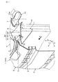
図1及び図2に示されるように、本実施形態の、車両100の前部構造1は、車両100の前側部分を構成するものであり、バンパ2、グリル部材3、フード4、吸気ダクト10、コンデンサ11、ラジエータ12、及び遮水機構20を備えている。
As shown in FIGS. 1 and 2, the
バンパ2は、車両100の最前部に設けられている。このバンパ2は、車両100の前方衝突時の衝撃や振動を和らげる機能を有する。このバンパ2は、合成樹脂材料からなる一体成型品として構成されている。
The
グリル部材3は、バンパ2の裏面側に取付けられている。このグリル部材3は、バンパ2の剛性を高めバンパ2の撓み変形を小さく抑える機能を有する。このグリル部材3は、合成樹脂材料からなる。
The grill member 3 is attached to the back side of the
フード4は、バンパ2の上方に配置され、エンジンルーム7を開閉可能に覆うように構成されている。このフード4を「ボンネット」ともいう。
The
上記のグリル部材3は、外気をエンジンルーム7に導入するための外気導入開口部5を備えている。また、上記のバンパ2は、外気をエンジンルーム7に導入するための外気導入開口部6を備えている。
The grill member 3 includes an outside
外気導入開口部6は、第3方向Zについて外気導入開口部5の下方に配置され、且つその開口面積が外気導入開口部5の開口面積を上回るように構成されている。このため、車両100の冠水路などの走行時(以下、「冠水走行時」という。)においては、外気導入開口部6から侵入する水の勢いが外気導入開口部5から侵入する水の勢いを上回る。
The outside
エンジンルーム7には、吸気ダクト10、空調用のコンデンサ11、エンジン冷却用のラジエータ12、及び遮水機構20が配置されている。
An
吸気ダクト10は、エンジン(図示省略)に供給されるエンジン供給用の空気を導入する吸気口10aを有する。この吸気口10aは、車両前方或いは車両上方に向けて開口している。
The
遮水機構20は、外気導入開口部6からエンジンルーム7に入り込んだ水の流れを遮る機能を有する。この遮水機構20は、第3方向Zについて外気導入開口部5と外気導入開口部6との間の位置に配置されている。
The
遮水機構20は、エンジンルーム7において吸気ダクト10の吸気口10aよりも前方且つ低所に設けられた遮水部材21と、遮水部材21の後方側に設けられた支持部材22と、シール部材23と、を備えている。遮水部材21及び支持部材22はいずれも、軽量化のために合成樹脂材料によって構成されるのが好ましい。
The water-
遮水部材21は、吸気ダクト10の吸気口10aに向かう上向きの水の流れを遮る機能(以下、単に「遮水機能」ともいう。)を有する。この遮水部材21は、エンジンルーム7において歩行者の脚部(脚部のうち膝や脛の周辺部位)に相当する高さに位置するように構成されている。
The water-
また、この遮水部材21の車両後方側には干渉回避空間8が予め設けられている。この干渉回避空間8は、コンデンサ11及びラジエータ12よりも上方の空間を利用して形成されており、遮水部材21と他部材との干渉を回避するための空間である。換言すれば、この干渉回避空間8から他部材が排除されている。
Further, an
この干渉回避空間8の大きさは、遮水部材21の寸法(第2方向Y及び第3方向Zについての寸法)、及び車両100の前方衝突時に遮水部材21が移動すると予測される領域に関する情報(典型的には、予め実施された衝突実験から得られる情報)などに基づいて予め設定されるのが好ましい。
The size of the
遮水部材21は、車両100の前方衝突時の衝突荷重(車両100の前方衝突時に車体のバンパ2側から受ける荷重)を受けたとき、この衝突荷重によって干渉回避空間8を車両後方へ移動することができる。このとき、遮水部材21は、干渉回避空間8を利用することによって他部材との干渉が回避されおり、この遮水部材21による反力が殆ど生じることがない。
When the water-
支持部材22は、遮水部材21を干渉回避空間8に向けて車両後方へスライド可能に支持する機能(以下、単に「支持機能」ともいう。)と、遮水部材21と同様の遮水機能と、を有する。
The
シール部材23は、遮水部材21と支持部材22との間に介装されており、遮水部材21と支持部材22との間をシールする機能を有する。
The
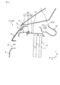
図3に示されるように、遮水部材21は、バンパ2側の固定部21aにおいて車体に固定されるとともに、この固定部21aから干渉回避空間8に向けて車両後方へ延出した後方延出部21bを有する。このため、遮水部材21は、固定部21aを固定端とし且つ後方延出部21bを自由端とした構造、所謂「片持ち支持構造」を有する。
As shown in FIG. 3, the water-
遮水部材21の固定部21aは、第2方向Y及び第3方向Zの双方によって規定される平面に沿って延在する平板状の部位として構成されている。遮水部材21の後方延出部21bは、第1方向X及び第2方向Yの双方によって規定される平面に沿って延在する平板状の部位として構成されている。
The fixing
更に、遮水部材21の後方延出部21bは、延出先端に向かうにつれて上向きに傾斜した重なり部21cを有する。即ち、重なり部21cは、後方延出部21bの延出先端側が高所となり、固定部21a側が低所となるように傾斜している。
Furthermore, the
支持部材22は、吸気ダクト10側の固定部22aにおいて車体に固定されるとともに、この固定部22aから車両前方へ延出した前方延出部22bを有する。このため、支持部材22は、固定部22aを固定端とし且つ前方延出部22bを自由端とした構造、所謂「片持ち支持構造」を有する。支持部材22の前方延出部22bは、第1方向X及び第2方向Yの双方によって規定される平面に沿って延在する平板状の部位として構成されている。
The
支持部材22は、その前方延出部22bが遮水部材21の後方延出部21bと車両上下方向である第3方向Zについて重なり且つ後方延出部21bを下方から支持するとともに、コンデンサ11及びラジエータ12の双方の上部を覆うように構成されている。この構成に関して、支持部材22の一部である前方延出部22bが既知のシュラウドアッパーカバー(カバー部材)を兼務している。
The
支持部材22の前方延出部22bは更に、延出先端に向かうにつれて下向きに傾斜した重なり部22cと、この重なり部22cから下向きに屈曲した屈曲部22dと、を有する。重なり部22cは、遮水部材21の重なり部21cと車両上下方向である第3方向Zについて互いに重なるように構成されている。このとき、遮水部材21及び支持部材22は、重なり部21cと重なり部22cとが互いに平行に延在し、重なり部22cが例えば水平面Sに対して傾斜角度θで延在するように構成されている。屈曲部22dは、第2方向Y及び第3方向Zの双方によって規定される平面に沿って延在する平板状の部位として構成されている。
The front extending
シール部材23は、遮水部材21の重なり部21cと支持部材22の重なり部22cとの間の介装されている。このシール部材23は、合成ゴムであるエチレン・プロピレン・ジエンゴム(EPDMゴム)を主成分とした発泡体(「スポンジ」もいう)からなる。この発泡体は、水及び音等に対するシール性を有する柔軟な材料である。従って、このシール部材23は、水シール部材であるとともに吸音部材でもある。
The
このシール部材23は、支持部材22の重なり部22cに固定されるとともに、遮水部材21の重なり部21cに対しては固定されることなく密着している。このため、遮水部材21が支持部材22に対して第1のスライド方向R1或いは第2のスライド方向R2に移動したとき、シール部材23はその柔軟性によって遮水部材21の重なり部21cとの密着状態を維持した状態でこの重なり部21cと摺動する。このため、このシール部材23による上記のシール性を維持できる。
The
次に、図3を参照しつつ、車両100のエンジンルーム7に侵入した水の流れについて説明する。
Next, the flow of water that has entered the
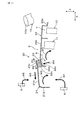
車両100の冠水走行時において、外気導入開口部6からエンジンルーム7に侵入した水は、その勢いによって上昇しながら第1流れW1にしたがって上向きに流れる。その後、遮水部材21まで達した水は、この遮水部材21の下面によって下方に跳ね返され、第2流れW2にしたがって流下する。同様に、支持部材22まで達した水は、この支持部材22の下面によって下方に跳ね返され、第3流れW3にしたがって流下する。これにより、吸気口10aに向かって流れる水の流れが遮水部材21及び支持部材22の双方によって遮られる。この場合、遮水部材21を第1の遮水部材としたとき、支持部材22は第2の遮水部材として構成されている。
When the
また、支持部材22に対しては、上向きの第4流れW4によってこの支持部材22の重なり部22cを遮水部材21の重なり部21cに向けて押圧する荷重が作用する。従って、支持部材22の重なり部22cは、この第4流れW4によってシール部材23を介して遮水部材21の重なり部21cに押し付けられる。このため、遮水部材21の重なり部21cと支持部材22の重なり部22cとの間の水シール性が向上する。
Further, a load that presses the overlapping
このとき、支持部材22の重なり部22cと屈曲部22dとの境界である隅部22eには上向きの第4流れW4による荷重が集中し易い。従って、屈曲部22dの助けによって、重なり部22cを重なり部21cに向けてより強く押し付けることが可能になる。なお、重なり部21cと重なり部22cとの間の水シール性を所望のレベルに維持できる場合には、支持部材22の屈曲部22dを省略することができる。
At this time, the load due to the upward fourth flow W4 tends to concentrate on the
これに対して、外気導入開口部5からエンジンルーム7に侵入した水は、重力により第5流れW5にしたがって下向きに流れる。その後、遮水部材21まで達した水は、この遮水部材21の上面を第6流れW6にしたがって流れる。ここで、遮水部材21の重なり部21cは、固定部21a側が低所となるように傾斜しているため、遮水部材21まで達した水は、この傾斜にしたがって固定部21a側へ流れ易い。
On the other hand, the water that has entered the
上記の実施形態によれば、以下のような作用効果が得られる。 According to said embodiment, the following effects are obtained.
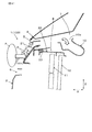
車両100の前部構造1において、遮水部材21は、吸気ダクト10の吸気口10aに向かう上向きの水の流れを遮ることによって吸気ダクト10への水の侵入を抑制することができる。一方で、図4に示されるように、車両100が前方衝突によって歩行者Pの脚部(脚部のうち膝や脛の周辺部位)と衝突した場合、衝突荷重を受けた遮水部材21は、シール部材23との間の僅かな摺動抵抗を除いて、干渉回避空間8を他部材からの抵抗を受けることなく車両後方へ移動する。このとき、遮水部材21は、前方衝突前の状態から殆ど変形することがない。なお、図4では、バンパ2及び遮水部材21について、前方衝突前の位置を二点鎖線で示し、前方衝突後の位置を実線で示している。
In the
このため、前方衝突時の衝突荷重に対して遮水部材21が抵抗になるのを回避できる。その結果、吸気ダクト10への水の侵入を抑制するとともに、前方衝突時に歩行者Pの脚部が車両100から受ける反力(衝撃)を低く抑えることが可能になる。即ち、遮水部材21による遮水性能と歩行者保護性能との両立が可能になる。
For this reason, it can avoid that the water-
また、上記の前部構造1によれば、遮水部材21を支持部材22によって干渉回避空間8に確実に移動させることができる。
Further, according to the
また、上記の前部構造1によれば、遮水部材21を支持する支持部材22が上向きの水の流れによって遮水部材21に押し付けられるため、遮水部材21の重なり部21cと支持部材22の重なり部22cとの間の水シール性を向上させることができる。また、遮水部材21は、バンパ2側の固定部21aを固定端とし後方延出部21bを自由端とした片持ち構造となるが、この後方延出部21bが支持部材22の前方延出部22bによって下方から支持されるため、遮水部材21の片持ち長さ(車両前後方向の長さ)を短く抑えることができる。
Moreover, according to said
また、上記の前部構造1によれば、支持部材22の重なり部22cと屈曲部22dとの境界部分である隅部22eに上向きの水の流れによる荷重を集中的に作用させることができ、遮水部材21の重なり部21cと支持部材22の重なり部22cとの間の水シール性を更に向上させることができる。
Further, according to the
また、上記の前部構造1によれば、遮水部材21の重なり部21cと支持部材22の重なり部22cとが互いに平行に延在しているため、遮水部材21が車両後方へスライドする動作が支持部材22によって邪魔されにくく、遮水部材21を干渉回避空間8に向けて円滑に移動させることができる。
Moreover, according to said
また、上記の前部構造1によれば、遮水部材21と支持部材22との間にシール部材23が介装されているため、遮水部材21の重なり部21cと支持部材22の重なり部22cとの間を通って水や音が侵入するのを抑制できる。
Moreover, according to said
また、上記の前部構造1によれば、遮水部材21を支持するための支持部材22にこの遮水部材21と同様の機能を付与することによって、2つの遮水部材21,22を用いて吸気ダクト10の吸気口10aに向かう上向きの水の流れを広範囲にわたって遮ることができる。
Moreover, according to said
また、上記の前部構造1によれば、支持部材22がその機能とシュラウドアッパーカバーの機能とを兼務しており合理的である。
Moreover, according to said
本発明は、上記の典型的な実施形態のみに限定されるものではなく、本発明の目的を逸脱しない限りにおいて種々の応用や変形が考えられる。例えば、上記の実施形態を応用した次の各形態を実施することもできる。 The present invention is not limited to the above-described exemplary embodiments, and various applications and modifications can be considered without departing from the object of the present invention. For example, the following embodiments applying the above-described embodiment can be implemented.
上記の実施形態では、遮水部材21及び支持部材22の双方を備える遮水機構20について例示したが、遮水機構20において支持部材22を省略することもできる。この場合、遮水部材21のみが遮水機能を果たす。
In the above embodiment, the
上記の実施形態では、支持部材22が支持機能及び遮水機能の両機能を備える場合について例示したが、支持部材22が支持機能及び遮水機能のいずれか一方のみを有する構成を採用することもできる。
In said embodiment, although illustrated about the case where the
上記の実施形態では、遮水部材21と支持部材22との間にシール部材23が介装される場合について例示したが、必要に応じてこのシール部材23を省略することもできる。シール部材23を省略した場合、遮水部材21が支持部材22によって支持される構成や、遮水部材21と支持部材22が隙間を介して対向する構成を採用することができる。
In the above embodiment, the case where the
上記の実施形態では、支持部材22がシュラウドアッパーカバーを兼務する場合について例示したが、シュラウドアッパーカバーとは別の部材、例えば吸気ダクト10の一部を利用して支持部材22を構成することもできる。また、支持部材22は、コンデンサ11及びラジエータ12の少なくとも一方の上部を覆うように構成されていればよい。
In the above-described embodiment, the case where the
上記の実施形態では、遮水部材21の重なり部21cと支持部材22の重なり部22cとが互いに平行に延在する場合について例示したが、必要に応じて重なり部21cと重なり部22cが互いに異なる方向に延在する構成を採用することもできる。
In the above embodiment, the case where the overlapping
1 前部構造
2 バンパ
8 干渉回避空間
10 吸気ダクト
10a 吸気口
11 コンデンサ
12 ラジエータ
20 遮水機構
21 遮水部材(第1の遮水部材)
21b 後方延出部
21c 重なり部
22 支持部材(シュラウドアッパーカバー、第2の遮水部材)
22b 前方延出部
22c 重なり部
22d 屈曲部
23 シール部材
100 車両
DESCRIPTION OF
21b
22b
Claims (8)
上記吸気ダクトの上記吸気口よりも低所に設けられ、上記吸気口に向かう上向きの水の流れを遮る遮水部材と、
を備え、
上記遮水部材は、車両の前方衝突時の衝突荷重によって、該遮水部材の車両後方側に予め設けられた干渉回避空間を車両後方へ移動するように構成されている、車両の前部構造。 An intake duct having an intake port for introducing air for engine supply;
A water-impervious member that is provided at a lower position than the intake port of the intake duct and blocks an upward flow of water toward the intake port;
With
The front structure of the vehicle is configured such that the water shielding member is configured to move to an interference avoidance space provided in advance on the vehicle rear side of the water shielding member due to a collision load at the time of a frontal collision of the vehicle. .
Priority Applications (1)
| Application Number | Priority Date | Filing Date | Title |
|---|---|---|---|
| JP2016082214A JP6725791B2 (en) | 2016-04-15 | 2016-04-15 | Vehicle front structure |
Applications Claiming Priority (1)
| Application Number | Priority Date | Filing Date | Title |
|---|---|---|---|
| JP2016082214A JP6725791B2 (en) | 2016-04-15 | 2016-04-15 | Vehicle front structure |
Publications (2)
| Publication Number | Publication Date |
|---|---|
| JP2017190105A true JP2017190105A (en) | 2017-10-19 |
| JP6725791B2 JP6725791B2 (en) | 2020-07-22 |
Family
ID=60086114
Family Applications (1)
| Application Number | Title | Priority Date | Filing Date |
|---|---|---|---|
| JP2016082214A Active JP6725791B2 (en) | 2016-04-15 | 2016-04-15 | Vehicle front structure |
Country Status (1)
| Country | Link |
|---|---|
| JP (1) | JP6725791B2 (en) |
Citations (8)
| Publication number | Priority date | Publication date | Assignee | Title |
|---|---|---|---|---|
| JPS6220952U (en) * | 1985-07-22 | 1987-02-07 | ||
| JPH074133U (en) * | 1993-06-17 | 1995-01-20 | マツダ株式会社 | Air intake structure of automobile |
| JP2002337552A (en) * | 2001-05-22 | 2002-11-27 | Toyoda Gosei Co Ltd | Automotive opening weather strip |
| JP2003072396A (en) * | 2001-08-31 | 2003-03-12 | Honda Motor Co Ltd | Air intake structure around the front grill of the vehicle |
| JP2006027596A (en) * | 2004-07-12 | 2006-02-02 | Honda Motor Co Ltd | Inlet air system for bulkhead for automobile |
| JP2008247122A (en) * | 2007-03-29 | 2008-10-16 | Mazda Motor Corp | Body front structure |
| JP2015113042A (en) * | 2013-12-12 | 2015-06-22 | 富士重工業株式会社 | Body front structure |
| JP2015116888A (en) * | 2013-12-17 | 2015-06-25 | マツダ株式会社 | Front part structure of vehicle |
-
2016
- 2016-04-15 JP JP2016082214A patent/JP6725791B2/en active Active
Patent Citations (8)
| Publication number | Priority date | Publication date | Assignee | Title |
|---|---|---|---|---|
| JPS6220952U (en) * | 1985-07-22 | 1987-02-07 | ||
| JPH074133U (en) * | 1993-06-17 | 1995-01-20 | マツダ株式会社 | Air intake structure of automobile |
| JP2002337552A (en) * | 2001-05-22 | 2002-11-27 | Toyoda Gosei Co Ltd | Automotive opening weather strip |
| JP2003072396A (en) * | 2001-08-31 | 2003-03-12 | Honda Motor Co Ltd | Air intake structure around the front grill of the vehicle |
| JP2006027596A (en) * | 2004-07-12 | 2006-02-02 | Honda Motor Co Ltd | Inlet air system for bulkhead for automobile |
| JP2008247122A (en) * | 2007-03-29 | 2008-10-16 | Mazda Motor Corp | Body front structure |
| JP2015113042A (en) * | 2013-12-12 | 2015-06-22 | 富士重工業株式会社 | Body front structure |
| JP2015116888A (en) * | 2013-12-17 | 2015-06-25 | マツダ株式会社 | Front part structure of vehicle |
Also Published As
| Publication number | Publication date |
|---|---|
| JP6725791B2 (en) | 2020-07-22 |
Similar Documents
| Publication | Publication Date | Title |
|---|---|---|
| JP5227063B2 (en) | Intake duct for vehicle | |
| JP5758233B2 (en) | Automotive front structure | |
| JP6614191B2 (en) | Vehicle front structure | |
| CN102092422A (en) | Air guide plate for automobile and sealing structure | |
| JP5474151B2 (en) | Intake duct for vehicle | |
| JP6527551B2 (en) | Intake duct module | |
| JP6131838B2 (en) | Vehicle front structure | |
| JP6048389B2 (en) | Automotive front structure | |
| JP6725791B2 (en) | Vehicle front structure | |
| US9676354B2 (en) | Bumper absorber structure | |
| JP5767842B2 (en) | Body front structure | |
| JP5801122B2 (en) | Pedestrian protection device for vehicles | |
| JP6004182B2 (en) | Front pillar air noise reduction structure | |
| KR101443198B1 (en) | Bumper module | |
| JP6339481B2 (en) | Bumper absorber and seal structure | |
| US20170057554A1 (en) | Cowl structure | |
| JP2008049935A (en) | Body front structure | |
| JP5715180B2 (en) | Automobile intake duct structure | |
| JP2016030522A (en) | Radiator grill | |
| JP6863239B2 (en) | Vehicle front structure | |
| JP5746542B2 (en) | Vehicle cooling air introduction device | |
| JP6090264B2 (en) | Automotive front structure | |
| KR101846920B1 (en) | Bumper beam for vehicles | |
| JP6048388B2 (en) | Automotive front structure | |
| JP6056674B2 (en) | Body front structure |
Legal Events
| Date | Code | Title | Description |
|---|---|---|---|
| A621 | Written request for application examination |
Free format text: JAPANESE INTERMEDIATE CODE: A621 Effective date: 20180625 |
|
| A977 | Report on retrieval |
Free format text: JAPANESE INTERMEDIATE CODE: A971007 Effective date: 20190419 |
|
| A131 | Notification of reasons for refusal |
Free format text: JAPANESE INTERMEDIATE CODE: A131 Effective date: 20190507 |
|
| A521 | Request for written amendment filed |
Free format text: JAPANESE INTERMEDIATE CODE: A523 Effective date: 20190612 |
|
| A131 | Notification of reasons for refusal |
Free format text: JAPANESE INTERMEDIATE CODE: A131 Effective date: 20191112 |
|
| A521 | Request for written amendment filed |
Free format text: JAPANESE INTERMEDIATE CODE: A523 Effective date: 20191216 |
|
| TRDD | Decision of grant or rejection written | ||
| A01 | Written decision to grant a patent or to grant a registration (utility model) |
Free format text: JAPANESE INTERMEDIATE CODE: A01 Effective date: 20200519 |
|
| A61 | First payment of annual fees (during grant procedure) |
Free format text: JAPANESE INTERMEDIATE CODE: A61 Effective date: 20200601 |
|
| R150 | Certificate of patent or registration of utility model |
Ref document number: 6725791 Country of ref document: JP Free format text: JAPANESE INTERMEDIATE CODE: R150 |
|
| R250 | Receipt of annual fees |
Free format text: JAPANESE INTERMEDIATE CODE: R250 |
|
| R250 | Receipt of annual fees |
Free format text: JAPANESE INTERMEDIATE CODE: R250 |
|
| R250 | Receipt of annual fees |
Free format text: JAPANESE INTERMEDIATE CODE: R250 |