JP2017190470A - Heat treatment equipment - Google Patents
Heat treatment equipment Download PDFInfo
- Publication number
- JP2017190470A JP2017190470A JP2016078743A JP2016078743A JP2017190470A JP 2017190470 A JP2017190470 A JP 2017190470A JP 2016078743 A JP2016078743 A JP 2016078743A JP 2016078743 A JP2016078743 A JP 2016078743A JP 2017190470 A JP2017190470 A JP 2017190470A
- Authority
- JP
- Japan
- Prior art keywords
- light irradiation
- heat treatment
- irradiation unit
- treatment apparatus
- heating
- Prior art date
- Legal status (The legal status is an assumption and is not a legal conclusion. Google has not performed a legal analysis and makes no representation as to the accuracy of the status listed.)
- Pending
Links
Images


Landscapes
- Heat Treatments In General, Especially Conveying And Cooling (AREA)
- Waste-Gas Treatment And Other Accessory Devices For Furnaces (AREA)
- Furnace Details (AREA)
Abstract
Description
本発明は、金属板を加熱処理する熱処理装置に関するものである。 The present invention relates to a heat treatment apparatus for heat-treating a metal plate.
従来、鋼板を高強度に加工する手段としてホットプレス(ダイクエンチ)がある。これは、鋼板を高温に加熱し、高温域でプレス加工する技術であり、特に鋼板を変態温度以上(約900℃以上)でプレス加工し、金型で急速に冷却することによってプレス圧がかかった状態で変態を生じさせることにより、高強度のプレス加工品を製造する技術である。
鋼板を高温に加熱する手段としては、赤外線の照射による加熱手段が期待されている。例えば、特許文献1には、鋼板の一面に赤外線を照射する直管型の加熱ランプが多数設けられ、鋼板の輪郭形状に応じて各々の加熱ランプの出力強度を調整することによって、所望の領域を高温に加熱する手段が開示されている。
Conventionally, there is a hot press (die quench) as a means for processing a steel plate with high strength. This is a technology that heats a steel plate to a high temperature and presses it in a high temperature range, and in particular, presses the steel plate at a transformation temperature or higher (about 900 ° C or higher) and rapidly cools it with a mold. This is a technique for producing a high-strength press-processed product by causing transformation in a heated state.
As a means for heating the steel sheet to a high temperature, a heating means by infrared irradiation is expected. For example, Patent Document 1 includes a large number of straight tube-type heating lamps that irradiate one surface of a steel plate with infrared rays, and by adjusting the output intensity of each heating lamp according to the contour shape of the steel plate, a desired region can be obtained. Means for heating to a high temperature is disclosed.
また、プレス加工品の生産性や品質を向上させるために、厚みの異なる部分を有する鋼板(以下、「差厚鋼板」ともいう。)をプレス加工する技術が提案されている(例えば、特許文献2参照)。このように差厚鋼板に対してプレス加工を行うことができると、溶接工程が不要となって生産時間を大きく短縮することができる。
しかしながら、差厚鋼板を加熱処理する場合は、鋼板の厚みによって到達する加熱温度が異なり易く、鋼板全体を均質に所望の温度に加熱することが難しい、という問題がある。
また上記の差厚鋼板に限らず、輪郭が特殊な形状の鋼板を加熱する際にも、部分的な温度ムラが生じ易く、このような温度ムラがプレス加工時の鋼板の品質に影響を及ぼしてしまう、という問題もある。
In addition, in order to improve the productivity and quality of a press-processed product, a technique for pressing a steel plate having portions with different thicknesses (hereinafter also referred to as “different thickness steel plate”) has been proposed (for example, patent document). 2). Thus, if a press work can be performed with respect to a difference thickness steel plate, a welding process will become unnecessary and production time can be reduced significantly.
However, when heat-treating a differential thickness steel plate, there is a problem that the heating temperature reached easily depends on the thickness of the steel plate, and it is difficult to uniformly heat the entire steel plate to a desired temperature.
Also, not only the above-mentioned differential thickness steel plates, but also when heating a steel plate with a special outline, partial temperature unevenness is likely to occur, and such temperature unevenness affects the quality of the steel plate during press working. There is also a problem that it ends up.
本発明は、以上のような事情に基づいてなされたものであって、その目的は、差厚鋼板や輪郭が特殊な形状の鋼板などの異形状の加熱対象物を加熱処理する場合においても、その全体を均質に所望の温度に加熱処理することができる熱処理装置を提供することにある。 The present invention has been made based on the circumstances as described above, and its purpose is to heat-treat an irregularly shaped heating object such as a differential thickness steel plate or a steel plate having a special contour. An object of the present invention is to provide a heat treatment apparatus capable of uniformly heat-treating the whole to a desired temperature.
本発明の熱処理装置は、処理室と、当該処理室内において略平板状の加熱対象物を局所的に接するよう支持する支持部と、前記処理室内において前記支持部に支持される加熱対象物の一面と対向するよう設けられた光照射部とを備え、前記光照射部から赤外線を照射して前記支持部に支持された加熱対象物を加熱処理する熱処理装置において、
前記光照射部は、前記加熱対象物が伸びるべき面方向に沿って縦横に並設された複数の点光源型の加熱ランプよりなり、
前記各加熱ランプからの赤外線の出力強度が、前記加熱対象物の形状に応じて各々独立に制御されることを特徴とする。
The heat treatment apparatus of the present invention includes a processing chamber, a support portion that supports a substantially flat heating target object locally in the processing chamber, and one surface of the heating target object that is supported by the support portion in the processing chamber. In a heat treatment apparatus for heat-treating a heating target object supported by the support unit by irradiating infrared light from the light irradiation unit,
The light irradiation unit is composed of a plurality of point light source type heating lamps arranged side by side in the vertical and horizontal directions along the surface direction to which the heating object should extend,
Infrared output intensity from each heating lamp is controlled independently according to the shape of the heating object.
本発明の熱処理装置においては、前記加熱対象物がその下面に前記支持部が局所的に接するよう載置されることにより支持され、
前記処理室内に、加熱対象物が載置される載置領域を介して前記光照射部と対向する状態に、当該載置領域に向かって赤外線を照射する反対側光照射部が設けられ、
前記反対側光照射部からの赤外線の出力量が、前記光照射部からの赤外線の出力量よりも大きいことが好ましい。
In the heat treatment apparatus of the present invention, the object to be heated is supported by being placed so that the support portion locally contacts the lower surface thereof,
In the processing chamber, an opposite light irradiation unit that irradiates infrared light toward the mounting region is provided in a state of facing the light irradiation unit via the mounting region on which the heating object is mounted,
It is preferable that the amount of infrared light output from the opposite side light irradiation unit is larger than the amount of infrared light output from the light irradiation unit.
本発明の熱処理装置においては、前記加熱対象物がその下面に前記支持部が局所的に接するよう支持され、
前記処理室内に、加熱対象物が載置される載置領域を介して前記光照射部と対向する状態に、当該載置領域に向かって赤外線を照射する反対側光照射部が設けられ、
前記載置領域における、前記光照射部および前記反対側光照射部からの赤外線が照射される領域が、前記支持部によって赤外線が遮断されて照射されない領域よりも大きいことが好ましい。
In the heat treatment apparatus of the present invention, the object to be heated is supported so that the support portion locally contacts the lower surface thereof,
In the processing chamber, an opposite light irradiation unit that irradiates infrared light toward the mounting region is provided in a state of facing the light irradiation unit via the mounting region on which the heating object is mounted,
It is preferable that the region where the infrared rays from the light irradiation unit and the opposite side light irradiation unit are irradiated in the placement region is larger than a region where the infrared rays are blocked by the support unit and not irradiated.
本発明の熱処理装置においては、前記支持部が、保持台と当該保持台の上面から突出する複数の突起部とからなり、
前記加熱対象物が前記複数の突起部に接して支持されることが好ましい。
In the heat treatment apparatus of the present invention, the support portion comprises a holding base and a plurality of protrusions protruding from the upper surface of the holding base,
It is preferable that the heating object is supported in contact with the plurality of protrusions.
本発明の熱処理装置においては、前記支持部が、内部に冷却媒体を流動させるための冷却流路を有することが好ましい。 In the heat processing apparatus of this invention, it is preferable that the said support part has a cooling flow path for making a cooling medium flow inside.
本発明の熱処理装置においては、前記支持部が、赤外線を透過する材料により形成されることが好ましい。 In the heat treatment apparatus of the present invention, it is preferable that the support portion is formed of a material that transmits infrared rays.
本発明の熱処理装置においては、前記光照射部を構成する複数の点光源型の加熱ランプが、シングルエンド型のフィラメントランプであることが好ましい。 In the heat treatment apparatus of the present invention, it is preferable that the plurality of point light source type heating lamps constituting the light irradiation unit are single-ended filament lamps.
本発明の熱処理装置においては、前記点光源型の加熱ランプが、略球型の封体に発光部が収容されたものであり、前記封体の内表面または外表面に反射コーティングが施されていることが好ましい。 In the heat treatment apparatus of the present invention, the point light source type heating lamp has a light emitting part accommodated in a substantially spherical envelope, and a reflective coating is applied to an inner surface or an outer surface of the envelope. Preferably it is.
本発明の熱処理装置においては、前記点光源型の加熱ランプが、筒形状の封体に発光部が収容されたものであり、前記封体の内周面または外周面に反射コーティングが施されていることが好ましい。 In the heat treatment apparatus of the present invention, the point light source type heating lamp has a light emitting part housed in a cylindrical envelope, and a reflective coating is applied to an inner peripheral surface or an outer peripheral surface of the envelope. Preferably it is.
本発明の熱処理装置においては、前記反対側光照射部が、棒状のダブルエンド型のフィラメントランプが並設されて構成されることが好ましい。 In the heat treatment apparatus of the present invention, it is preferable that the opposite side light irradiation unit is configured by arranging rod-shaped double-ended filament lamps in parallel.
本発明の熱処理装置においては、前記加熱対象物が、互いに厚みの異なる部分を有し、
前記光照射部が配置された平面と同じ平面上に、当該平面が伸びる方向に伸びるよう配置された棒状の加熱ランプよりなる同側光照射部が設けられ、
前記光照射部を構成する点光源型の加熱ランプが、前記加熱対象物の厚みの異なる部分の境界を含む領域に対応する領域に配置されると共に、
前記同側光照射部を構成する棒状の加熱ランプが、前記加熱対象物の厚みの異なる部分の境界を含まない領域に対応する領域に配置されることが好ましい。
In the heat treatment apparatus of the present invention, the heating object has portions having different thicknesses,
On the same plane as the plane on which the light irradiation unit is disposed, a same-side light irradiation unit made of a rod-shaped heating lamp disposed to extend in the direction in which the plane extends is provided,
The point light source type heating lamp constituting the light irradiation unit is disposed in a region corresponding to a region including a boundary of a portion having a different thickness of the heating object,
It is preferable that the rod-shaped heating lamp which comprises the said ipsilateral light irradiation part is arrange | positioned in the area | region corresponding to the area | region which does not include the boundary of the part from which the thickness of the said heating target object differs.
本発明の熱処理装置は、縦横に並設された複数の点光源型の加熱ランプの各々の赤外線の出力強度が、加熱対象物の形状に応じて各々独立に制御されるものである。従って、差厚鋼板や輪郭が特殊な形状の鋼板などの異形状の加熱対象物を加熱処理する場合においても、各点光源型の加熱ランプの赤外線の出力強度を個別に制御することにより、加熱温度分布を当該加熱対象物の厚みや輪郭に応じたものとすることができるので、全体を均質に所望の温度に加熱処理することができる。 In the heat treatment apparatus of the present invention, the infrared output intensity of each of the plurality of point light source type heating lamps arranged side by side is controlled independently according to the shape of the object to be heated. Therefore, even when heating an irregularly shaped object to be heated, such as a differential thickness steel plate or a specially shaped steel plate, by controlling the infrared output intensity of each point light source type heating lamp individually, Since the temperature distribution can be made according to the thickness and contour of the heating object, the whole can be uniformly heat-treated at a desired temperature.
以下、本発明の実施の形態について説明する。 Embodiments of the present invention will be described below.
〔第1の実施の形態〕
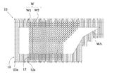
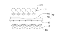
図1は、本発明の第1の実施の形態の熱処理装置の一例における構成の概略を示す平面図であり、図2は、図1の熱処理装置の断面の一部を拡大して示す断面図である。
この熱処理装置10は、処理室(図示せず)を有し、この処理室内において支持部15上に支持される略平板状の加熱対象物(以下、「ワーク」ともいう。)Wの上面および下面とそれぞれ対向するよう設けられた上側光照射部12および下側光照射部13とを備える。
この熱処理装置10において、ワークWは、処理室内において、例えばその下面が局所的に接するよう支持部15上に支持されることにより、ワークWが載置されるべき載置領域(以下、「ワーク載置領域」ともいう。)に載置されている。
この熱処理装置10は、上側光照射部12および下側光照射部13からそれぞれワーク載置領域に向かって赤外線を照射することにより、ワーク載置領域に載置されたワークWを両面から加熱して加熱処理するものである。
[First Embodiment]
FIG. 1 is a plan view schematically showing the configuration of an example of a heat treatment apparatus according to the first embodiment of the present invention, and FIG. 2 is an enlarged cross-sectional view showing a part of the cross section of the heat treatment apparatus of FIG. It is.
The
In the
The
〔ワーク〕
この熱処理装置10において加熱処理されるワークWは、略平板状の鋼板であればその詳細な形状について限定されず、厚みが均一な平板状の鋼板であっても差厚鋼板であってもよく、また、輪郭が長方形や正方形のものであっても輪郭が特殊な形状のものであってもよい。
具体的には、長方形の輪郭のもの(図3(a))、尖った部位を有する輪郭のもの(図3(b))、輪郭に曲線を有するもの(図3(c))、辺の長さが互いに異なる輪郭のもの(図3(d)や図3(e))、穴を有するもの(図3(f))などや、これらの異なる2種を積層させた、厚みの異なる部分を有する差厚鋼板などが挙げられる。
差厚鋼板としては、例えば図1および図2に示されるように、互いに形状が異なる下層ワークW1および上層ワークW2が積層されたワークWが挙げられる。
〔work〕
The work W to be heat-treated in the
Specifically, those having a rectangular outline (FIG. 3A), those having a sharp part (FIG. 3B), those having a curved line in the outline (FIG. 3C), Parts with different thicknesses with different lengths (Fig. 3 (d) and Fig. 3 (e)), with holes (Fig. 3 (f)), etc., or by stacking these two different types And a differential thickness steel plate having
Examples of the differential thickness steel plate include a workpiece W in which a lower layer workpiece W1 and an upper layer workpiece W2 having different shapes are stacked as shown in FIGS.
〔上側光照射部〕
上側光照射部12は、ワーク載置領域における異なる略円状の加熱領域にそれぞれ対応するよう、ワークWが伸びる面方向に沿って縦横に並設された複数の点光源型の加熱ランプ(以下、「点状ランプ」ともいう。)12aよりなる。
上側光照射部12においては、温度制御性の観点から、隣接する点状ランプ12aの距離が全て等間隔となるよう設置されていることが好ましい。
点状ランプ12aの加熱領域は狭いので、熱処理装置10に点状ランプ12aが用いられることによってワークWの部分的な加熱がし易い。
[Upper light irradiation part]
The
In the upper
Since the heating area of the
上側光照射部12には、各点状ランプ12aからの赤外線の出力強度を、ワークWの厚み形状および輪郭形状に応じて各々独立に制御する制御手段(図示せず)が設けられている。
制御手段においては、ワーク載置領域における各略円状の加熱領域に対応する各点状ランプ12aに対して、赤外線の出力強度を調整する制御が行われる。具体的には、例えば、ワーク載置領域における一の略円状の加熱領域における、載置されるワークWの厚みが厚い場合には対応する点状ランプ12aの赤外線の出力強度を大きくし、当該ワークWの厚みが薄い場合には対応する点状ランプ12aの赤外線の出力強度を小さくする。
制御手段においては、各点状ランプ12aについて点灯または消灯を選択することにより、赤外線の出力強度を制御する構成であってもよい。
The upper
In the control means, control for adjusting the output intensity of infrared rays is performed on each of the
The control means may be configured to control the output intensity of infrared rays by selecting lighting or extinguishing for each
点状ランプ12aとしては、例えばシングルエンド型のフィラメントランプを用いることができる。
As the
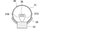
図4は、シングルエンド型のフィラメントランプの構成の一例を示す断面図である。
このシングルエンド型のフィラメントランプは、例えば石英ガラスよりなる球欠体状の封体(バルブ)21を備え、当該バルブ21の割平面がセラミックよりなるソケット25によって封止されている。
バルブ21内には、例えばタングステンよりなる1本の線材がコイル状に巻回されて形成されたフィラメント26よりなる発光部がその巻回軸がバルブ21の割平面に沿って伸びるよう配置されると共に、例えばハロゲンガスが封入されている。
フィラメント26の一端部は、一方の内部リード27Aの一端側部分に接続されており、他端部は他方の内部リード27Bの一端部に接続されている。
一方の内部リード27Aおよび他方の内部リード27Bの他端部は、それぞれ、ソケット25内に設けられた2つの電極(図示せず)に接続されている。
FIG. 4 is a cross-sectional view showing an example of the configuration of a single-ended filament lamp.
This single-ended filament lamp includes a spherically shaped envelope (bulb) 21 made of, for example, quartz glass, and a split plane of the
In the
One end of the
The other end portions of one
シングルエンド型のフィラメントランプにおいては、バルブ21の内表面または外表面における、ワークWと対向する側と反対側に位置する領域に、当該シングルエンド型のフィラメントランプからの光を反射させて当該ワークWに向かって放射する反射部材29が設けられることが好ましい。バルブ21の外表面における反射部材29が形成されていない領域によって光取り出し部28が形成されている。
反射部材29は、具体的には、例えばソケット25からバルブ21の外表面に沿って伸びる球帯状の反射コーティングや反射板よりなるものとすることができる。
シングルエンド型のフィラメントランプは、光取り出し部28がワークWと対向するように配置される。
このような反射部材29を備えるシングルエンド型のフィラメントランプを用いることにより、高い加熱効率が得られる。
In the single-ended filament lamp, light from the single-ended filament lamp is reflected on a region located on the inner surface or outer surface of the
Specifically, the reflecting
The single-ended filament lamp is arranged so that the
By using a single-ended filament lamp including such a reflecting
〔下側光照射部〕
下側光照射部13は、例えばワーク載置領域における異なる棒状の加熱領域にそれぞれ対応するよう、複数の棒状の加熱ランプ(以下、「棒状ランプ」ともいう。)13aが、各々のランプ中心軸がワークWの伸びる面と平行となるように一平面内に位置された状態で、互いに離間して並設されている。
棒状ランプ13aの各々は、隣接する棒状ランプ13aの距離が全て等間隔となるよう設置されていることが好ましい。
(Lower light irradiation part)
The lower
Each of the rod-shaped
下側光照射部13は、各棒状ランプ13aとして、ワークWの輪郭形状に応じて異なる長さのものを組み合わせて用いて構成されていてもよい。具体的には、例えば図1に示されるように、輪郭が端部になるに従って幅(図1において上下方向長さ)の短くなる形状の鋭角部WAを有するワークWを加熱処理する場合は、4種類の長さのものを当該鋭角部の輪郭に応じて並べられた構成とすることができる。
The lower
下側光照射部13においては、各棒状ランプ13aの赤外線の出力強度は、全て同じとされる。
In the lower
棒状ランプ13aとしては、例えばダブルエンド型のフィラメントランプを用いることができる。
As the rod-shaped
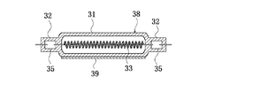
図5は、ダブルエンド型のフィラメントランプの構成の一例を示す断面図である。
このダブルエンド型のフィラメントランプは、両端に封止部32,32が形成された、例えばガラス材料よりなる直管状の発光管31を有し、この発光管31の内部空間に、例えばハロゲンガスが封入されると共に、例えばタングステン素線がコイル状に巻回されて形成されたコイル状のフィラメント33が、発光管31の管軸に沿って伸びるよう配置されてなる。このダブルエンド型のフィラメントランプにおける封止部32,32にはフィラメント33に電気的に接続された金属箔35,35の各々が埋設されている。
ダブルエンド型のフィラメントランプには、当該ダブルエンド型のフィラメントランプの管軸(発光管31の管軸)に沿って伸びる帯状の反射部材39が、発光管31の外周面におけるワークWに対向する側と反対側に位置する領域に形成されており、発光管31の外周面における反射部材39が形成されていない領域によって光取り出し部38が形成されている。
ダブルエンド型のフィラメントランプは、光取り出し部38がワークWと対向するように配置される。
FIG. 5 is a cross-sectional view showing an example of the configuration of a double-ended filament lamp.
This double-ended filament lamp has a straight
In the double-ended filament lamp, a strip-shaped reflecting
The double-ended filament lamp is arranged so that the
〔支持部〕
本発明の熱処理装置10においては、上側光照射部12と下側光照射部13との間にワークWが載置される支持部15が存在することから、ワーク載置領域には当該支持部15によって赤外線が遮断される領域が存在することがある。このため、支持部15は、ワーク載置領域における、上側光照射部12および下側光照射部13からの赤外線が照射される領域が、赤外線が遮断されて照射されない領域よりも大きくなる構成とされることが好ましい。
このような構成を有する熱処理装置10によれば、支持部15による赤外線の遮断を小さく抑制することができるので、ワークWを確実に均質に加熱処理することができる。
また、加熱処理においてワークWに発生した熱は、当該ワークWを載置する支持部15に伝熱されて除熱されてしまう。このため、支持部15は、ワークWの除熱を抑制する観点から、ワークWの支持部15との接触面積を小さく抑制することができる構成とされることが好ましい。
(Support part)
In the
According to the
In addition, the heat generated in the workpiece W in the heat treatment is transferred to the
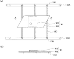
例えば支持部15は、図6に示されるように、2本の平行に設けられた梁部材15A,15Bと、当該梁部材15A,15Bと鉛直に伸びてこれらの梁部材15A,15Bに支持される複数の支持棒15Cとからなるものとすることができる。この支持部15には、ワークWが梁部材15A,15Bには接さずに支持棒15Cのみに接する状態で支持される。
支持棒15Cは、その両端が、一方の梁部材15Aに形成された凹部15Hおよび他方の梁部材15Bに形成された凹部15Hに嵌合されることによって支持されている。
支持部15における支持棒15Cの数は、ワークWの重量によっても異なるが、例えば3本とすることができる。
梁部材15A,15Bにおける支持棒15Cの存在位置は、ワークWの輪郭形状によって適宜に変更することができる。具体的には、梁部材15A,15Bにおいては、互いに所定の距離を隔てて多数の凹部15Hが形成されており、加熱処理すべきワークWの輪郭形状によって支持棒15Cの梁部材15A,15Bにおける嵌合位置を選択することができる。
For example, as shown in FIG. 6, the
The
The number of
The position of the
支持部15を構成する部材、特に上記の例の支持部15における支持棒15CなどのワークWと下側光照射部13との間に介在される部材は、赤外線を透過する材料により形成されていることが好ましい。
The members constituting the
また、支持部15を構成する部材としては、ワークWの重量が大きい場合には、ワークWを所望のワーク載置領域に精確に載置することができるよう、金属製のものを用いることが好ましい。この場合、ワークWに接する部材は熱によって劣化し易いので、支持部15には、ワークWの加熱処理を損なわない程度に冷却する冷却機構が設けられていてもよい。
Moreover, as a member which comprises the
上記の熱処理装置10の点状ランプ12aおよび棒状ランプ13aの寸法の一例、および、これらの配置位置の一例を挙げると、点状ランプ12aのバルブ21の外径が26mm、フィラメント26の長さが7.6mm、配置ピッチが30mmであり、棒状ランプ13aの外径が15mm、フィラメント33の長さがそれぞれ700mm、350m、300mmおよび250mm、配置ピッチが20mmである。
As an example of the dimensions of the
上記の熱処理装置10においては、ワークWの上面および下面に、それぞれ上側光照射部12および下側光照射部13から赤外線が照射される。このとき、下側光照射部13からの赤外線の出力量(合計の赤外線の出力強度)は、上側光照射部12からの赤外線の出力量(合計の赤外線の出力強度)よりも大きくされる。このように赤外線の出力量が制御されることにより、加熱処理においてワークW全体の昇温レートを高めながら当該ワークW全体を均質に所望の温度に加熱処理することができる。
この熱処理装置10においては、異なる形状のワークが積層されたワークWを加熱する場合は、小さな形状のワークが上側となるよう支持部15に載置する。そして、まず、下側光照射部13を構成する各棒状ランプ13aのフィラメント33から放射された赤外線が、直接または反射部材39によって反射されることにより光取り出し部38から出射されて、ワークWの下面に照射される。これにより、基本的にワークW全体が加熱される。一方、上側光照射部12においては、各点状ランプ12aからの赤外線の出力強度がワークWの厚み形状および輪郭形状に応じて制御手段によって各々独立に制御された状態において、各点状ランプ12aのフィラメント26から放射された赤外線が、直接または反射部材29によって反射されることにより光取り出し部28から出射されて、ワークWの上面に照射され、当該ワークWの形状に応じた加熱温度分布で加熱される。
加熱処理の加熱温度は、例えば1000℃±50℃とされる。
In the
In this
The heating temperature of the heat treatment is, for example, 1000 ° C. ± 50 ° C.
以上のような第1の実施の形態の熱処理装置10によれば、縦横に並設された複数の点状ランプ12aの各々の赤外線の出力強度が、ワークWの形状に応じて各々独立に制御されるものである。従って、差厚鋼板や輪郭が特殊な形状の鋼板などの異形状のワークWを加熱処理する場合においても、各点状ランプ12aの赤外線の出力強度を個別に制御することにより、加熱温度分布を当該ワークWに応じたものとすることができるので、全体を均質に所望の温度に加熱処理することができる。
According to the
〔第2の実施の形態〕
図7は、本発明の第2の実施の形態の熱処理装置の一例における構成の概略を示す平面図である。
この熱処理装置60は、熱処理の対象となるワークWが互いに厚みの異なる部分を有する差厚鋼板であるものである。そして、下側光照射部13が設けられておらず、上側光照射部12の代わりに、ワークWの形状および厚みに応じて、第1光照射部62および第2光照射部63が、それぞれ単数または複数設けられていること以外は第1の実施の形態に係る熱処理装置と同様の構成である。第1の実施の形態に係る熱処理装置10と同様の構成を有するものを同じ符号で示す。
この熱処理装置60は、第1光照射部62および第2光照射部63からそれぞれワーク載置領域に向かって赤外線を照射することにより、ワーク載置領域に載置されたワークWを上面から加熱して加熱処理するものである。
[Second Embodiment]
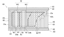
FIG. 7 is a plan view schematically showing the configuration of an example of the heat treatment apparatus according to the second embodiment of the present invention.
This
The
この熱処理装置60は、具体的には、第1光照射部62は、ワーク載置領域における異なる略円状の加熱領域にそれぞれ対応するよう、ワークWが伸びる面方向に沿って縦横に並設された点状ランプ12aよりなる。
第1光照射部62においては、温度制御性の観点から、隣接する点状ランプ12aの距離が全て等間隔となるよう設置されていることが好ましい。
第1光照射部62には、各点状ランプ12aからの赤外線の出力強度を、ワークWの厚み形状および輪郭形状に応じて各々独立に制御する制御手段(図示せず)が設けられている。
制御手段においては、ワーク載置領域における各略円状の加熱領域に対応する各点状ランプ12aに対して、赤外線の出力強度を調整する制御が行われる。具体的には、例えば、ワーク載置領域における一の略円状の加熱領域における、載置されるワークWの厚みが厚い場合には対応する点状ランプ12aの赤外線の出力強度を大きくし、当該ワークWの厚みが薄い場合には対応する点状ランプ12aの赤外線の出力強度を小さくする。
制御手段においては、各点状ランプ12aについて点灯または消灯を選択することにより、赤外線の出力強度を制御する構成であってもよい。
Specifically, in the
In the 1st
The first
In the control means, control for adjusting the output intensity of infrared rays is performed on each of the
The control means may be configured to control the output intensity of infrared rays by selecting lighting or extinguishing for each
また、第2光照射部63は、点状ランプ12aが配置された平面と同じ平面上に、ワーク載置領域における異なる棒状の加熱領域にそれぞれ対応するよう、ワークWが伸びる面方向に沿って並設された複数の棒状ランプ13aよりなる。
棒状ランプ13aの各々は、隣接する棒状ランプ13aの距離が全て等間隔となるよう設置されていることが好ましい。
第2光照射部63は、各棒状ランプ13aとして、ワークWの輪郭形状に応じて異なる長さのものを組み合わせて用いて構成されていてもよい。
第2光照射部63においては、各棒状ランプ13aの赤外線の出力強度は、全て同じとされる。
In addition, the second
Each of the rod-shaped
The 2nd
In the 2nd
そして、この熱処理装置60においては、ワークWの厚み形状および輪郭形状に応じて、ワーク載置領域における各ランプからの赤外線の出力強度が各々独立に制御されるべき加熱領域に対応するよう、第1光照射部62が設けられると共に、残りのワーク載置領域に対応するよう第2光照射部63が設けられる。
具体的には、第1光照射部62は、ワークWの厚みの異なる部分の境界を含む段差領域に対応する領域(図7の鎖線で囲った領域A1)や、ワークWの端部を含む端部領域に対応する領域(図7の鎖線で囲った領域A2)、ワークWの輪郭が端部になるに従って幅の短くなる形状の鋭角部WAを含む異形領域に対応する領域、および、これらの複合領域に対応する領域(図7の鎖線で囲った領域A3)に設けられる。
また、ワークWが存在するがワークWの厚みの異なる部分の境界を含まないフラット領域に対応する領域(図7の鎖線で囲った領域A4a、A4b)や、ワークWが存在しない周辺領域に対応する領域(図7の鎖線で囲った領域A5)に、第2光照射部63が設けられる。
And in this
Specifically, the first
Further, it corresponds to a flat region (the regions A4a and A4b surrounded by a chain line in FIG. 7) corresponding to a flat region where the workpiece W exists but does not include the boundary of the portions having different thicknesses of the workpiece W, and a peripheral region where the workpiece W does not exist. The second
複数の第2光照射部63を構成する棒状ランプ13a同士は、同じ方向に伸びていなくてもよい。
The rod-shaped
このような熱処理装置60によれば、第1の実施の形態に係る熱処理装置10と同様の効果が得られ、さらに、点状ランプおよび棒状ランプの合計のランプ本数の低減を行うことができる。
According to such a
以上、本発明の第1の実施の形態および第2の実施の形態について説明したが、本発明は上記の実施形態に限定されるものではなく、種々の変更を加えることができる。
例えば、第1の実施の形態の熱処理装置においては、赤外線の出力強度が各々独立に制御される点状ランプの複数よりなる光照射部が上側光照射部12としてワーク載置領域の上側に設けられていることに限定されず、ワーク載置領域の下側に設けられて当該ワーク載置領域に載置されるワークの下面に赤外線を照射する構成とされていてもよい。
また例えば、第1の実施の形態の熱処理装置においては、赤外線の出力強度が各々独立に制御される点状ランプの複数よりなる光照射部が備えられていれば、反対側光照射部すなわち棒状ランプ13aよりなる下側光照射部13が設けられることに限定されない。
The first embodiment and the second embodiment of the present invention have been described above. However, the present invention is not limited to the above-described embodiment, and various modifications can be made.
For example, in the heat treatment apparatus according to the first embodiment, a light irradiation unit including a plurality of point lamps whose infrared output intensity is independently controlled is provided as an upper
Further, for example, in the heat treatment apparatus according to the first embodiment, if a light irradiation unit composed of a plurality of point lamps each independently controlling the output intensity of infrared rays is provided, the opposite side light irradiation unit, that is, a rod shape It is not limited to the lower side
また例えば、第1の実施の形態および第2の実施の形態の熱処理装置においては、点状ランプ12aとして、短躯筒形状の封体に発光部が収容されたランプを用いてもよい。このようなランプにおいては、封体の内周面または外周面に反射コーティングが施されていることが好ましい。
Further, for example, in the heat treatment apparatuses of the first embodiment and the second embodiment, a lamp in which a light emitting part is accommodated in a short rod-shaped envelope may be used as the
また例えば、第2の実施の形態の熱処理装置においては、一の第2光照射部63を構成する棒状ランプ13は1本であってもよい。
Further, for example, in the heat treatment apparatus according to the second embodiment, the number of the rod-shaped
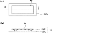
また例えば、第1の実施の形態および第2の実施の形態の熱処理装置においては、支持部は上記の構成に限定されず、図8に示されるように、保持台45Aと当該保持台45Aの上面から突出する複数の突起部45Bとからなるものとすることができる。この支持部45において、ワークWは保持台45Aと接しない状態において、複数の突起部45Bに接して支持される。
また、支持部は、図9に示されるように、例えば内部が冷却媒体を流動させるための冷却流路とされた銅管55Aが同一平面上において多数のU字が形成されるよう、いわゆるつづら折り状に伸びてなる支持部55であってもよい。
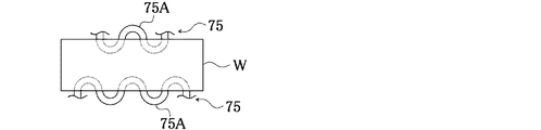
また、下側光照射部13からワーク載置領域への赤外線が遮断される領域を小さくする観点から、図10に示されるように、例えば内部に冷却流路を有する銅管75Aがつづら折り状に伸びてなる支持部75が、ワークWの両端部のみを接触してするよう設けられていてもよい。
さらに、支持部によって赤外線が遮断されることによってワークWの加熱が抑制されることを防止する観点から、支持部を構成する部材を、耐熱性のセラミックからなるセラミックヒータからなるものとしてもよい。
Further, for example, in the heat treatment apparatuses according to the first embodiment and the second embodiment, the support portion is not limited to the above configuration, and as shown in FIG. 8, the holding table 45A and the holding table 45A It can be composed of a plurality of
In addition, as shown in FIG. 9, the support portion is so-called zigzag folded so that, for example, a
Further, from the viewpoint of reducing the area where infrared rays from the lower
Furthermore, from the viewpoint of preventing the heating of the workpiece W from being suppressed by the infrared ray being blocked by the support portion, the member constituting the support portion may be made of a ceramic heater made of heat-resistant ceramic.
さらに例えば、第1の実施の形態の熱処理装置において下側光照射部13が設けられない構成を有する場合、および第2の実施の形態の熱処理装置においては、ワークWが支持部上に載置されて支持される構成に限定されず、ワークが鉛直方向に伸びる姿勢で、上部から吊り下げる、若しくは、加熱処理中のワークの反りを吸収するために上下から張力をかけた状態で支持される垂直支持方式で支持される構成とされていてもよい。
Furthermore, for example, in the case where the lower
10 熱処理装置
12 上側光照射部
12a 点状ランプ
13 下側光照射部
13a 棒状ランプ
15 支持部
15A,15B 梁部材
15C 支持棒
15H 凹部
21 バルブ
25 ソケット
26 フィラメント
27A,27B 内部リード
28 光取り出し部
29 反射部材
31 発光管
32 封止部
33 フィラメント
35 金属箔
38 光取り出し部
39 反射部材
45 支持部
45A 保持台
45B 突起部
55 支持部
55A 銅管
60 熱処理装置
62 第1光照射部
63 第2光照射部
75 支持部
75A 銅管
W ワーク
W1 下層ワーク
W2 上層ワーク
WA 鋭角部
DESCRIPTION OF
Claims (11)
前記光照射部は、前記加熱対象物が伸びるべき面方向に沿って縦横に並設された複数の点光源型の加熱ランプよりなり、
前記各加熱ランプからの赤外線の出力強度が、前記加熱対象物の形状に応じて各々独立に制御されることを特徴とする熱処理装置。 A processing chamber, a support portion that supports a substantially flat heating target object locally in the processing chamber, and a surface of the heating target object that is supported by the support portion in the processing chamber. In a heat treatment apparatus comprising a light irradiation unit, and heat-treating a heating object supported by the support unit by irradiating infrared light from the light irradiation unit,
The light irradiation unit is composed of a plurality of point light source type heating lamps arranged side by side in the vertical and horizontal directions along the surface direction to which the heating object should extend,
Infrared output intensity from each heating lamp is independently controlled according to the shape of the heating object.
前記処理室内に、加熱対象物が載置される載置領域を介して前記光照射部と対向する状態に、当該載置領域に向かって赤外線を照射する反対側光照射部が設けられ、
前記反対側光照射部からの赤外線の出力量が、前記光照射部からの赤外線の出力量よりも大きいことを特徴とする請求項1に記載の熱処理装置。 The heated object is supported by being placed so that the support portion locally contacts the lower surface thereof,
In the processing chamber, an opposite light irradiation unit that irradiates infrared light toward the mounting region is provided in a state of facing the light irradiation unit via the mounting region on which the heating object is mounted,
2. The heat treatment apparatus according to claim 1, wherein an output amount of infrared rays from the opposite-side light irradiation unit is larger than an output amount of infrared rays from the light irradiation unit.
前記処理室内に、加熱対象物が載置される載置領域を介して前記光照射部と対向する状態に、当該載置領域に向かって赤外線を照射する反対側光照射部が設けられ、
前記載置領域における、前記光照射部および前記反対側光照射部からの赤外線が照射される領域が、前記支持部によって赤外線が遮断されて照射されない領域よりも大きいことを特徴とする請求項1または請求項2に記載の熱処理装置。 The object to be heated is supported so that the support portion locally contacts the lower surface thereof,
In the processing chamber, an opposite light irradiation unit that irradiates infrared light toward the mounting region is provided in a state of facing the light irradiation unit via the mounting region on which the heating object is mounted,
The area where the infrared rays from the light irradiation part and the opposite light irradiation part in the placement area are irradiated is larger than the area where the infrared rays are blocked by the support part and not irradiated. Or the heat processing apparatus of Claim 2.
前記加熱対象物が前記複数の突起部に接して支持されることを特徴とする請求項1〜請求項3のいずれかに記載の熱処理装置。 The support portion includes a holding table and a plurality of protrusions protruding from the upper surface of the holding table.
The heat treatment apparatus according to claim 1, wherein the object to be heated is supported in contact with the plurality of protrusions.
前記光照射部が配置された平面と同じ平面上に、当該平面が伸びる方向に伸びるよう配置された棒状の加熱ランプよりなる同側光照射部が設けられ、
前記光照射部を構成する点光源型の加熱ランプが、前記加熱対象物の厚みの異なる部分の境界を含む領域に対応する領域に配置されると共に、
前記同側光照射部を構成する棒状の加熱ランプが、前記加熱対象物の厚みの異なる部分の境界を含まない領域に対応する領域に配置されることを特徴とする請求項1に記載の熱処理装置。
The heating object has portions with different thicknesses,
On the same plane as the plane on which the light irradiation unit is disposed, a same-side light irradiation unit made of a rod-shaped heating lamp disposed to extend in the direction in which the plane extends is provided,
The point light source type heating lamp constituting the light irradiation unit is disposed in a region corresponding to a region including a boundary of a portion having a different thickness of the heating object,
2. The heat treatment according to claim 1, wherein the bar-shaped heating lamp constituting the same-side light irradiation unit is disposed in a region corresponding to a region not including a boundary between portions having different thicknesses of the heating object. apparatus.
Priority Applications (1)
| Application Number | Priority Date | Filing Date | Title |
|---|---|---|---|
| JP2016078743A JP2017190470A (en) | 2016-04-11 | 2016-04-11 | Heat treatment equipment |
Applications Claiming Priority (1)
| Application Number | Priority Date | Filing Date | Title |
|---|---|---|---|
| JP2016078743A JP2017190470A (en) | 2016-04-11 | 2016-04-11 | Heat treatment equipment |
Publications (1)
| Publication Number | Publication Date |
|---|---|
| JP2017190470A true JP2017190470A (en) | 2017-10-19 |
Family
ID=60086069
Family Applications (1)
| Application Number | Title | Priority Date | Filing Date |
|---|---|---|---|
| JP2016078743A Pending JP2017190470A (en) | 2016-04-11 | 2016-04-11 | Heat treatment equipment |
Country Status (1)
| Country | Link |
|---|---|
| JP (1) | JP2017190470A (en) |
Citations (5)
| Publication number | Priority date | Publication date | Assignee | Title |
|---|---|---|---|---|
| JP2002134430A (en) * | 2000-10-24 | 2002-05-10 | Tokyo Electron Ltd | Lamp having high reflectivity film for improving directivity and heat treatment apparatus |
| US20090320968A1 (en) * | 2008-06-30 | 2009-12-31 | Johannes Boeke | Differential heat shaping and hardening using infrared light |
| JP2011099567A (en) * | 2009-11-03 | 2011-05-19 | Ken Kk | Infrared heating device, infrared irradiating device, and infrared irradiating direction adjusting device |
| WO2013145229A1 (en) * | 2012-03-29 | 2013-10-03 | アイシン高丘株式会社 | Metal processing method and metal article processed thereby |
| JP2014522911A (en) * | 2011-06-30 | 2014-09-08 | エープナー インドゥストリーオーフェンバウ ゲー・エム・ベー・ハー | Method for heating a molded part for subsequent press hardening and a continuous furnace for partially heating a molded part preheated to a predetermined temperature |
-
2016
- 2016-04-11 JP JP2016078743A patent/JP2017190470A/en active Pending
Patent Citations (5)
| Publication number | Priority date | Publication date | Assignee | Title |
|---|---|---|---|---|
| JP2002134430A (en) * | 2000-10-24 | 2002-05-10 | Tokyo Electron Ltd | Lamp having high reflectivity film for improving directivity and heat treatment apparatus |
| US20090320968A1 (en) * | 2008-06-30 | 2009-12-31 | Johannes Boeke | Differential heat shaping and hardening using infrared light |
| JP2011099567A (en) * | 2009-11-03 | 2011-05-19 | Ken Kk | Infrared heating device, infrared irradiating device, and infrared irradiating direction adjusting device |
| JP2014522911A (en) * | 2011-06-30 | 2014-09-08 | エープナー インドゥストリーオーフェンバウ ゲー・エム・ベー・ハー | Method for heating a molded part for subsequent press hardening and a continuous furnace for partially heating a molded part preheated to a predetermined temperature |
| WO2013145229A1 (en) * | 2012-03-29 | 2013-10-03 | アイシン高丘株式会社 | Metal processing method and metal article processed thereby |
Similar Documents
| Publication | Publication Date | Title |
|---|---|---|
| US9678428B2 (en) | Light irradiating appatarus | |
| JP5937524B2 (en) | Infrared furnace, infrared heating method, and steel plate manufactured using the same | |
| JP5322358B2 (en) | Apparatus and method for heat treatment of substrate | |
| JP5931769B2 (en) | Infrared furnace and infrared heating method | |
| JP5267765B2 (en) | Filament lamp and light irradiation type heat treatment equipment | |
| JP2011099567A (en) | Infrared heating device, infrared irradiating device, and infrared irradiating direction adjusting device | |
| JP2017190470A (en) | Heat treatment equipment | |
| US7700899B2 (en) | Heating device of the light irradiation type | |
| JP2009238552A (en) | Filament lamp | |
| KR100902633B1 (en) | Heating unit and substrate processing apparatus having same | |
| JP4040030B2 (en) | Semiconductor manufacturing equipment | |
| KR100807120B1 (en) | Rapid heat treatment device | |
| JP5349802B2 (en) | Heat treatment equipment | |
| JP6183692B2 (en) | Heat treatment equipment | |
| JP4670886B2 (en) | Filament lamp | |
| JP6926603B2 (en) | Heating device | |
| CN113545166A (en) | Heat treatment method and light heating device | |
| US20250357157A1 (en) | Susceptor for supporting substrate, method of manufacturing susceptor, and heat treatment apparatus equipped with susceptor | |
| JP5274846B2 (en) | Heat treatment equipment | |
| KR101772180B1 (en) | Substrate supporting apparatus and substrate processing apparatus having the same | |
| JP5176782B2 (en) | Filament lamp | |
| JP2009231608A (en) | Heat treatment equipment | |
| JP2009302131A (en) | Heat treatment apparatus | |
| JP6502713B2 (en) | Heat treatment equipment | |
| KR101796214B1 (en) | Apparatus for processing substrate |
Legal Events
| Date | Code | Title | Description |
|---|---|---|---|
| RD03 | Notification of appointment of power of attorney |
Free format text: JAPANESE INTERMEDIATE CODE: A7423 Effective date: 20190131 |
|
| A621 | Written request for application examination |
Free format text: JAPANESE INTERMEDIATE CODE: A621 Effective date: 20190312 |
|
| A977 | Report on retrieval |
Free format text: JAPANESE INTERMEDIATE CODE: A971007 Effective date: 20191121 |
|
| A131 | Notification of reasons for refusal |
Free format text: JAPANESE INTERMEDIATE CODE: A131 Effective date: 20191224 |
|
| A521 | Request for written amendment filed |
Free format text: JAPANESE INTERMEDIATE CODE: A523 Effective date: 20200210 |
|
| RD04 | Notification of resignation of power of attorney |
Free format text: JAPANESE INTERMEDIATE CODE: A7424 Effective date: 20200706 |
|
| A02 | Decision of refusal |
Free format text: JAPANESE INTERMEDIATE CODE: A02 Effective date: 20200714 |