JP2017190575A - Sound insulation method - Google Patents
Sound insulation method Download PDFInfo
- Publication number
- JP2017190575A JP2017190575A JP2016079217A JP2016079217A JP2017190575A JP 2017190575 A JP2017190575 A JP 2017190575A JP 2016079217 A JP2016079217 A JP 2016079217A JP 2016079217 A JP2016079217 A JP 2016079217A JP 2017190575 A JP2017190575 A JP 2017190575A
- Authority
- JP
- Japan
- Prior art keywords
- vertical
- hole
- sound insulation
- urethane foam
- sound
- Prior art date
- Legal status (The legal status is an assumption and is not a legal conclusion. Google has not performed a legal analysis and makes no representation as to the accuracy of the status listed.)
- Granted
Links
Images

Landscapes
- Building Environments (AREA)
- Load-Bearing And Curtain Walls (AREA)
Abstract
Description
本発明は、後施工でカーテンウォールの中空形状の方立の遮音性能を向上させる遮音工法に関する。 The present invention relates to a sound insulation method for improving the sound insulation performance of a hollow shape of a curtain wall in post-construction.
従来より、外壁面にアルミニウム製のウォール(以下、ACWと呼ぶ)が採用された建物において、上下階間で特定の周波数の音が伝わってしまう場合があった。例えば、通常の会話はほとんど伝わらないが、マイクを通した声や拍手の音が伝わる場合があった。 Conventionally, in a building in which an aluminum wall (hereinafter referred to as ACW) is adopted as an outer wall surface, a sound having a specific frequency may be transmitted between upper and lower floors. For example, a normal conversation is hardly transmitted, but a voice through a microphone or a sound of applause may be transmitted.
そこで、本発明者らは、上階に音源、下階に音測定装置を設置し、ACWのガラスおよび方立に振動測定装置を取り付けて、音源で発生させた音の周波数、下階で測定した音圧レベル、ACWのガラス面および方立の振動数の相関関係を調査した。その結果、以下のような事実が判明した。 Therefore, the present inventors installed a sound source on the upper floor and a sound measuring device on the lower floor, and attached a vibration measuring device on the ACW glass and the vertical, and measured the frequency of the sound generated by the sound source on the lower floor. The correlation between the measured sound pressure level, the ACW glass surface and the vertical frequency was investigated. As a result, the following facts were found.
1.拍手の周波数帯域は、1kHz〜2kHzの間である。
2.上下階間の層間塞ぎの状況によらず、2kHz付近の周波数において、音圧レベルが高くなる。また、2kHz付近の周波数では、ACWのガラス面はほとんど振動しないが、方立が大きく振動している。
1. The frequency band of applause is between 1 kHz and 2 kHz.
2. Regardless of the situation of interlayer blocking between the upper and lower floors, the sound pressure level becomes high at a frequency near 2 kHz. Further, at a frequency of about 2 kHz, the ACW glass surface hardly vibrates, but the direction is greatly vibrated.
以上より、ACWの方立が音の伝搬経路となっているため、方立を囲んで遮音性能の高いシートやボードを配置することで、上下階間での遮音性能を高める方法が考えられる(例えば、特許文献1参照)。 From the above, since the ACW stand is the sound propagation path, a method of enhancing the sound insulation performance between the upper and lower floors by placing a sheet or board having a high sound insulation performance around the stand is considered ( For example, see Patent Document 1).
しかしながら、方立を遮音性能の高いシートやボードで囲むと、方立の外径が大きくなるため、意匠上の問題が生じるうえに、室内空間の使用形態に制約が生じる、という問題があった。 However, if the vertical is surrounded by a sheet or board with high sound insulation performance, the outer diameter of the vertical becomes large, which causes a problem in terms of design and a restriction in the usage form of the indoor space. .
本発明は、方立の外径を大きくすることなく、上下階間での遮音性能を向上できる遮音工法を提供することを目的とする。 An object of this invention is to provide the sound-insulation method which can improve the sound-insulation performance between the upper and lower floors, without enlarging the outer diameter of a vertical.
請求項1に記載の遮音工法は、後施工で、中空形状の方立(例えば、後述の方立20)を有するカーテンウォール(例えば、後述のカーテンウォール1、1A)の遮音性能を向上させる遮音工法であって、前記方立の所定箇所に、当該方立内部と外部とを連通する貫通孔(例えば、後述の貫通孔50A、50B)を形成する工程(例えば、後述のステップS2、S12)と、弾性変形可能な受け材(例えば、後述の受け材51)を用意し、当該受け材を前記貫通孔から前記方立の内部に挿入して、当該受け材により前記貫通孔よりも下側の高さ位置で前記方立の内部を閉塞する工程(例えば、後述のステップS3、S13)と、前記貫通孔から発泡ウレタン(例えば、後述の発泡ウレタン52)を注入して、前記方立の内部を閉塞する工程(例えば、後述のステップS4、S14)と、を備えることを特徴とする。
The sound insulation method according to claim 1 is a sound insulation method for improving the sound insulation performance of a curtain wall (for example,
この発明によれば、発泡ウレタンで方立の内部を閉塞したので、方立の外径を大きくすることなく、方立内部を通って上下階間で音が抜けるのを防止して、遮音性能を向上できる。また、方立内部に発泡ウレタンを注入するだけでよいので、低コストで施工可能である。 According to this invention, since the interior of the vertical is closed with urethane foam, the sound insulation performance is prevented by preventing the sound from passing between the upper and lower floors through the vertical without increasing the outer diameter of the vertical. Can be improved. In addition, since it is only necessary to inject urethane foam into the vertical interior, construction is possible at low cost.
請求項2に記載の遮音工法は、前記貫通孔を形成する工程では、前記貫通孔に加えて、当該貫通孔より上側に第2の貫通孔(例えば、後述の貫通孔50B)を形成し、前記発泡ウレタンを注入する工程の後に、当該第2の貫通孔からグラウト材(例えば、後述のグラウト材53)を注入して、前記発泡ウレタンの上に充填する工程(例えば、後述のステップS5)をさらに備えることを特徴とする。
In the sound insulation method according to claim 2, in the step of forming the through hole, in addition to the through hole, a second through hole (for example, a through
この発明によれば、グラウト材で方立の内部を閉塞したので、方立内部を通って上下階間で音が抜けるのをより確実に防止できる。また、方立内部にグラウト材を注入するだけでよいので、低コストで施工可能である。 According to this invention, since the interior of the vertical is closed with the grout material, it is possible to more reliably prevent sound from passing between the upper and lower floors through the interior of the vertical. Moreover, since it is only necessary to inject the grout material into the vertical, it can be constructed at low cost.
本発明によれば、方立の外径を大きくすることなく、上下階間での遮音性能を向上できる。 According to the present invention, it is possible to improve the sound insulation performance between the upper and lower floors without increasing the vertical outer diameter.
以下、本発明の実施形態を図面に基づいて説明する。なお、以下の実施形態の説明にあたって、同一構成要件については同一符号を付し、その説明を省略もしくは簡略化する。
〔第1実施形態〕
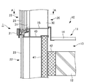
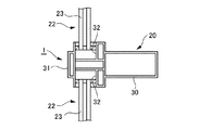
図1は、本発明の第1実施形態に係る遮音工法の適用対象となるカーテンウォール1を備える建物10の縦断面図である。図2は、図1のA−A断面図である。
カーテンウォール1は、建物10の外壁面を構成しており、この建物10の各フロア11の床スラブ12に設けられた図示しないブラケットおよびファスナで支持されている。
カーテンウォール1は、水平方向に所定間隔おきに配置されて上下方向に延びる方立20と、方立20同士の間に上下方向に所定間隔おきに配置されて水平方向に延びる無目21と、方立20および無目21で囲まれた開口部22に嵌め込まれた矩形状のガラスパネル23と、を備える。
Hereinafter, embodiments of the present invention will be described with reference to the drawings. In the following description of the embodiments, the same constituent elements are denoted by the same reference numerals, and the description thereof is omitted or simplified.
[First Embodiment]
FIG. 1 is a longitudinal sectional view of a
The curtain wall 1 constitutes the outer wall surface of the
The curtain wall 1 is arranged in the horizontal direction at predetermined intervals and extending in the vertical direction. The curtain wall 1 is arranged between the vertical 20 in the vertical direction at predetermined intervals and extending in the horizontal direction. A
方立20および無目21は、金属製であり、アルミニウムの押出成形等によって一体成形(長手方向に同一断面形状のまま連続して形成)されている。これら方立20および無目21は、角筒状の中空形状の本体30と、この本体30の屋外側に設けられた略H形状の取付部31と、を備える。
取付部31の両側面には、凹溝32が設けられ、この凹溝32には、ガラスパネル23の四辺が挿入されている。凹溝32とガラスパネル23との隙間には、バックアップ材が挿入された後、シーリング材が打設されており、これにより、ガラスパネル23が方立20および無目21に保持されている。
The vertical 20 and the
各フロア11は、二重床構造であり、床スラブ12の上には、OAフロア13が設けられている。OAフロア13は、床スラブ12の上に所定間隔おきに配置された図示しない支柱と、これら支柱の上に支持される矩形状の床パネル14と、を備える。
Each
無目21には、床スラブ12の端縁に沿って金属製で板状の耐火ボード受け40が取り付けられており、この耐火ボード受け40には、耐火材である耐火ボード41が取り付けられている。耐火ボード41の内壁面と床スラブ12の端面との隙間は、耐火材であるロックウール42で塞がれている。
無目21には、耐火ボード受け40および耐火ボード41を隠蔽する膳板15が設けられており、OAフロア13の床パネル14の端部は、この膳板15の端部まで延びている。
A metal plate-like
The blind 21 is provided with a
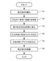
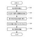
本発明では、建物10の完成後に後施工で、カーテンウォール1の遮音性能を向上させる遮音工事を行う。以下、この遮音工事の手順について、図3のフローチャートを参照しながら説明する。
ステップS1では、図4および図5に示すように、準備工事として、遮音工事を行う施工箇所を露出させる。具体的には、膳板15に取り合う床パネル14を取り外し、その後、膳板15を取り外して、方立20の床スラブ12の近傍の部分を露出させる。
In the present invention, the sound insulation work for improving the sound insulation performance of the curtain wall 1 is performed by post-construction after the
In step S1, as shown in FIG. 4 and FIG. 5, the construction site where the sound insulation work is performed is exposed as a preparation work. Specifically, the
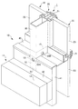
ステップS2では、図4および図5に示すように、方立20の上下二箇所に、方立20内部と外部とを連通する貫通孔50A、50Bを形成する。
具体的には、方立20の床スラブ12側の側面に、ドリルで貫通孔50Aを開ける。また、方立20の耐火ボード受け40側の側面のうち、耐火ボード受け40の上側でかつ膳板15よりも下側の位置に、ドリルで貫通孔50Bを開ける。この貫通孔50Bの高さ位置は、貫通孔50Aの高さ位置よりも高くしておく。
In step S2, as shown in FIGS. 4 and 5, through
Specifically, a
ステップS3では、図4および図5に示すように、弾性変形可能な樹脂製の受け材51を用意し、この受け材51を丸めて下側の貫通孔50Aから方立20の内部に挿入し、挿入後に復元させて拡げて、この受け材51により、貫通孔50Aよりも下側の高さ位置で方立20の内部を閉塞する。
In step S3, as shown in FIGS. 4 and 5, an elastically deformable
ステップS4では、図4および図5に示すように、下側の貫通孔50Aから方立20内部に発泡ウレタン52を注入して、方立20の内部を閉塞する。この発泡ウレタン52の上端の高さ位置は、上側の貫通孔50Bよりも低くする。充填した発泡ウレタン52は、発泡して硬化するまで、受け材51により下から支持される。
また、このとき、作業員がファイバースコープを貫通孔50Bから挿入して、発泡ウレタン52が方立20の内部に隙間なく充填されていることを確認する。発泡ウレタン52が方立20の内部との間に隙間が生じている場合には、貫通孔50Aや貫通孔50Bからへらを挿入し、このへらで発泡ウレタン52を寄せて隙間を塞ぐ。
In step S4, as shown in FIG. 4 and FIG. 5, the
At this time, the operator inserts the fiberscope from the through
ステップS5では、図4および図5に示すように、上側の貫通孔50Bから方立20内部にグラウト材53を注入して、方立20の内部でかつ発泡ウレタン52の上に充填する。充填したグラウト材53は、硬化するまで、発泡ウレタン52により下から支持される。
ステップS6では、遮音工事を行った施工箇所を隠蔽する。具体的には、膳板15および床パネル14を復旧して、方立20に設けた貫通孔50A、50Bを覆う。
In step S5, as shown in FIGS. 4 and 5, the
In step S6, the construction site where the sound insulation work has been performed is concealed. Specifically, the
本実施形態によれば、以下のような効果がある。
(1)発泡ウレタン52で方立20の内部を閉塞したので、方立20の外径を大きくすることなく、方立20の内部を通って上下階間で音が抜けるのを防止して、遮音性能を向上できる。また、方立20の内部に発泡ウレタン52を注入するだけでよいので、低コストで施工可能である。
According to this embodiment, there are the following effects.
(1) Since the inside of the vertical 20 is closed with the
(2)グラウト材53で方立20の内部を閉塞したので、方立20の内部を通って上下階間で音が抜けるのをより確実に防止できる。また、方立20の内部にグラウト材53を注入するだけでよいので、低コストで施工可能である。
(2) Since the inside of the vertical 20 is closed by the
〔第2実施形態〕
図5は、本発明の第2実施形態に係る遮音工法の適用対象となるカーテンウォール1Aの模式的な斜視図である。
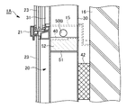
本実施形態では、室内側から視て、方立20の正面側つまり内側に柱16が位置しており(図7参照)、第1実施形態の貫通孔50Aを形成できない点が、第1実施形態と異なる。
以下、後施工でカーテンウォール1Aの遮音性能を向上させる手順について、図6のフローチャートを参照しながら説明する。
ステップS11は、第1実施形態のステップS1と同様である。
ステップS12では、図7に示すように、方立20の無目21側の側面に貫通孔50Bを設ける。
[Second Embodiment]
FIG. 5 is a schematic perspective view of a
In the present embodiment, as viewed from the indoor side, the
Hereinafter, the procedure for improving the sound insulation performance of the
Step S11 is the same as step S1 of the first embodiment.
In step S12, as shown in FIG. 7, the through-
ステップS13では、図7に示すように、弾性変形可能な受け材51を用意し、この受け材51を丸めて貫通孔50Bから方立20の内部に挿入し、挿入後に復元させて拡げて、この受け材51により貫通孔50Bよりも下側の高さ位置で方立20の内部を閉塞する。
In step S13, as shown in FIG. 7, an elastically deformable receiving
ステップS14では、図7に示すように、貫通孔50Bから発泡ウレタン52を注入して、方立20の内部に充填する。
ステップS15は、第1実施形態のステップS6と同様である。
In step S <b> 14, as shown in FIG. 7,
Step S15 is the same as step S6 of the first embodiment.
本実施形態によれば、上述の(1)と同様の効果がある。 According to the present embodiment, there is an effect similar to the above (1).
なお、本発明は前記実施形態に限定されるものではなく、本発明の目的を達成できる範囲での変形、改良等は本発明に含まれるものである。 It should be noted that the present invention is not limited to the above-described embodiment, and modifications, improvements, etc. within a scope that can achieve the object of the present invention are included in the present invention.
1、1A…カーテンウォール
10…建物 11…各フロア 12…床スラブ 13…OAフロア
14…床パネル 15…膳板 16…柱
20…方立 21…無目 22…開口部 23…ガラスパネル
30…本体 31…取付部 32…凹溝
40…耐火ボード受け 41…耐火ボード 42…ロックウール
50A…貫通孔 50B…貫通孔
51…受け材 52…発泡ウレタン 53…グラウト材
DESCRIPTION OF
Claims (2)
前記方立の所定箇所に、当該方立の内部と外部とを連通する貫通孔を形成する工程と、
弾性変形可能な受け材を用意し、当該受け材を前記貫通孔から前記方立の内部に挿入して、当該受け材により前記貫通孔よりも下側の高さ位置で前記方立の内部を閉塞する工程と、
前記貫通孔から発泡ウレタンを注入して、前記方立の内部を閉塞する工程と、を備えることを特徴とする遮音工法。 It is a sound insulation method that improves the sound insulation performance of curtain walls with a hollow shape in the post-construction,
A step of forming a through-hole communicating with the inside and the outside of the vertical at a predetermined position of the vertical;
An elastically deformable receiving material is prepared, and the receiving material is inserted into the vertical from the through hole, and the internal of the vertical is lowered by the receiving material at a lower position than the through hole. A blockage step;
And a step of injecting urethane foam from the through-hole to close the inside of the vertical body.
前記発泡ウレタンを注入する工程の後に、当該第2の貫通孔からグラウト材を注入して、前記発泡ウレタンの上に充填する工程をさらに備えることを特徴とする請求項1に記載の遮音工法。 In the step of forming the through hole, in addition to the through hole, a second through hole is formed above the through hole,
The sound insulation method according to claim 1, further comprising a step of injecting a grout material from the second through hole and filling the urethane foam after the step of injecting the urethane foam.
Priority Applications (1)
| Application Number | Priority Date | Filing Date | Title |
|---|---|---|---|
| JP2016079217A JP6635595B2 (en) | 2016-04-12 | 2016-04-12 | Sound insulation method |
Applications Claiming Priority (1)
| Application Number | Priority Date | Filing Date | Title |
|---|---|---|---|
| JP2016079217A JP6635595B2 (en) | 2016-04-12 | 2016-04-12 | Sound insulation method |
Publications (2)
| Publication Number | Publication Date |
|---|---|
| JP2017190575A true JP2017190575A (en) | 2017-10-19 |
| JP6635595B2 JP6635595B2 (en) | 2020-01-29 |
Family
ID=60085701
Family Applications (1)
| Application Number | Title | Priority Date | Filing Date |
|---|---|---|---|
| JP2016079217A Active JP6635595B2 (en) | 2016-04-12 | 2016-04-12 | Sound insulation method |
Country Status (1)
| Country | Link |
|---|---|
| JP (1) | JP6635595B2 (en) |
Cited By (2)
| Publication number | Priority date | Publication date | Assignee | Title |
|---|---|---|---|---|
| JP2022525093A (en) * | 2019-03-14 | 2022-05-11 | ヒルティ アクチエンゲゼルシャフト | The process for assembling a fireproof, smokeproof, soundproof and / or waterproof system within a dynamic curtain wall façade |
| CN115059191A (en) * | 2022-05-23 | 2022-09-16 | 无锡康城七恒零碳建筑科技有限公司 | Seven permanent passive forms PU external thermal insulation protection boundary strips |
Citations (2)
| Publication number | Priority date | Publication date | Assignee | Title |
|---|---|---|---|---|
| JPH0644829U (en) * | 1992-11-24 | 1994-06-14 | 大成建設株式会社 | Window stand |
| JP3095275U (en) * | 2003-01-16 | 2003-07-25 | 有限会社協栄建設 | Seismic structure of building walls, floor or ceiling |
-
2016
- 2016-04-12 JP JP2016079217A patent/JP6635595B2/en active Active
Patent Citations (2)
| Publication number | Priority date | Publication date | Assignee | Title |
|---|---|---|---|---|
| JPH0644829U (en) * | 1992-11-24 | 1994-06-14 | 大成建設株式会社 | Window stand |
| JP3095275U (en) * | 2003-01-16 | 2003-07-25 | 有限会社協栄建設 | Seismic structure of building walls, floor or ceiling |
Cited By (5)
| Publication number | Priority date | Publication date | Assignee | Title |
|---|---|---|---|---|
| JP2022525093A (en) * | 2019-03-14 | 2022-05-11 | ヒルティ アクチエンゲゼルシャフト | The process for assembling a fireproof, smokeproof, soundproof and / or waterproof system within a dynamic curtain wall façade |
| JP7282197B2 (en) | 2019-03-14 | 2023-05-26 | ヒルティ アクチエンゲゼルシャフト | Process for assembling fire, smoke, sound and/or waterproofing systems into dynamic curtain wall facades |
| US11970855B2 (en) | 2019-03-14 | 2024-04-30 | Hilti Aktiengesellschaft | Process for assembling a fire- , smoke- , sound- and/or water-proof system within a dynamic curtain wall façade |
| CN115059191A (en) * | 2022-05-23 | 2022-09-16 | 无锡康城七恒零碳建筑科技有限公司 | Seven permanent passive forms PU external thermal insulation protection boundary strips |
| CN115059191B (en) * | 2022-05-23 | 2023-11-28 | 无锡康城七恒零碳建筑科技有限公司 | Seven permanent passive PU external thermal insulation protection strakes |
Also Published As
| Publication number | Publication date |
|---|---|
| JP6635595B2 (en) | 2020-01-29 |
Similar Documents
| Publication | Publication Date | Title |
|---|---|---|
| KR101527077B1 (en) | Windows and doors curtain wall insulation system | |
| AU2018277051A1 (en) | Process for producing a recess in the base region of a wall construction, corresponding wall construction and system and construction element therefor | |
| JP2017190575A (en) | Sound insulation method | |
| KR101838656B1 (en) | Method of constructing wall for reducing structure-borne vibration-noise and air-borne sound of non-endurance wall | |
| JP2007303206A (en) | Vibration isolation structure of concrete construction | |
| JP5133731B2 (en) | Basic structure of unit type building and construction method of unit type building | |
| JP2020033728A (en) | Urethane heat insulation bearing wall | |
| JP6782058B1 (en) | Construction method of a wooden building using a perforated sheet-covered PC plate | |
| CN210134559U (en) | Grillage-in-one outer wall plate structure with heat insulation function and building | |
| JP2014234602A (en) | Earthquake-resisting wall and formation method thereof | |
| US20050109127A1 (en) | Structural beam member | |
| KR102216112B1 (en) | Bracket assembly for window frame and construction method thereof | |
| JP2502019B2 (en) | Anti-vibration structure of underground wall of building and its construction method | |
| KR102711282B1 (en) | Non-welding reinforcement finishing system for building finishing materials | |
| CN206800711U (en) | One kind spraying mortar beams encased in steel hoops interior wall pipe clamp connecting node | |
| KR102183021B1 (en) | Bracket assembly for window frame | |
| JP5216117B2 (en) | Fireproof wall structure provided in the opening of apartment houses and layout change method | |
| JP6817052B2 (en) | Fireproof coating construction method | |
| KR20130061340A (en) | Wall member having enhanced tightness | |
| KR101494657B1 (en) | Nonflammability panel and manufacturing process of the same | |
| JP2015124589A (en) | Attachment tool for interior and exterior material and concrete form | |
| KR102853197B1 (en) | Floor structure with reduced noise between floors and its construction method | |
| JP7074534B2 (en) | Wall structure of temporary building and its construction method | |
| JP2016069848A (en) | Joint material, slit structure of concrete structure, slitting method of concrete structure | |
| JP4567529B2 (en) | Seismic reinforcement heat insulation repair method |
Legal Events
| Date | Code | Title | Description |
|---|---|---|---|
| A621 | Written request for application examination |
Free format text: JAPANESE INTERMEDIATE CODE: A621 Effective date: 20190305 |
|
| A977 | Report on retrieval |
Free format text: JAPANESE INTERMEDIATE CODE: A971007 Effective date: 20191203 |
|
| TRDD | Decision of grant or rejection written | ||
| A01 | Written decision to grant a patent or to grant a registration (utility model) |
Free format text: JAPANESE INTERMEDIATE CODE: A01 Effective date: 20191212 |
|
| A61 | First payment of annual fees (during grant procedure) |
Free format text: JAPANESE INTERMEDIATE CODE: A61 Effective date: 20191216 |
|
| R150 | Certificate of patent or registration of utility model |
Ref document number: 6635595 Country of ref document: JP Free format text: JAPANESE INTERMEDIATE CODE: R150 |