JP2017190580A - Pre-drilling method in natural ground reinforcement method and natural ground reinforcement method - Google Patents
Pre-drilling method in natural ground reinforcement method and natural ground reinforcement method Download PDFInfo
- Publication number
- JP2017190580A JP2017190580A JP2016079376A JP2016079376A JP2017190580A JP 2017190580 A JP2017190580 A JP 2017190580A JP 2016079376 A JP2016079376 A JP 2016079376A JP 2016079376 A JP2016079376 A JP 2016079376A JP 2017190580 A JP2017190580 A JP 2017190580A
- Authority
- JP
- Japan
- Prior art keywords
- drilling
- bit
- hole
- main
- reinforcing pipe
- Prior art date
- Legal status (The legal status is an assumption and is not a legal conclusion. Google has not performed a legal analysis and makes no representation as to the accuracy of the status listed.)
- Granted
Links
Images



Landscapes
- Excavating Of Shafts Or Tunnels (AREA)
- Earth Drilling (AREA)
Abstract
【課題】下孔の位置を精度よく削孔できるとともに、補強管の削孔方向を精度よく削孔できて、作業時間を短縮できる下孔削孔方法を提供する。【解決手段】地山に下孔を削孔してから、その下孔より小径の本削孔を施すとともに、その本削孔内に補強管5を打設する地山補強工法において、補強管5の先端に取り付けた下孔削孔用ビット6で下孔を削孔する。その下孔削孔用ビットとして、削孔ロッド3の先端に備えたセンター削孔ビット4を通す中心穴を有する先行下孔削孔用リングビット6を用いて下孔を削孔する。その後、補強管5先端の下孔削孔用ビット6を取り外してから、下孔削孔用ビット6より小径の本削孔用ビット7を補強管5先端に取り付けて、その本削孔用ビット7で本削孔を施すとともに、その本削孔内に補強管5を打設する。【選択図】図1A pilot hole drilling method capable of accurately drilling the position of the pilot hole, accurately drilling the drilling direction of the reinforcing pipe, and shortening the working time is provided. SOLUTION: In a ground reinforcement construction method in which a pilot hole is drilled in the ground, main drilling of a smaller diameter is performed from the pilot hole, and a reinforcing pipe 5 is driven into the main drilled hole, the reinforcing pipe. A pilot hole is drilled with a pilot drilling bit 6 attached to the tip of 5 . As a bit for drilling the pilot hole, a ring bit 6 for preceding pilot hole drilling having a center hole through which a center drill bit 4 provided at the tip of the drilling rod 3 passes is used to drill the pilot hole. After that, after removing the pilot hole drilling bit 6 at the tip of the reinforcing pipe 5, a main drilling bit 7 having a smaller diameter than the pilot hole drilling bit 6 is attached to the tip of the reinforcing pipe 5, and the main drilling bit is attached. In 7, the main drilling is performed, and the reinforcement pipe 5 is driven into the main drilling. [Selection drawing] Fig. 1
Description
本発明は、地山補強工法における下孔削孔方法と、その下孔削孔方法を用いる地山補強工法に関する。 The present invention relates to a lower hole drilling method in a natural ground reinforcement method and a natural ground reinforcement method using the lower hole drilling method.
山岳トンネル工事に適用される長尺先受工法などの補強管を用いた地山補強工法において、長尺先受工法などで行われる薬液注入では、補強管の口元と地山との間から注入材がリークし、注入効果が損なわれ、適正な地山改良効果が得られないことがあるため、口元部を補強管より若干大径のビットで下孔を掘削し、補強管と下孔の間をシーリングして注入材のリークを防いでいた。
従来の下孔削孔では、下孔の芯と補強管の芯が一致せず、下孔と補強管の芯にずれが生じ、補強管の口元周りのシーリングが困難となることがあった。
このため、特許文献1では、下孔削孔用の専用ビットを用いて下孔を削孔した後、補強管と補強管削孔用ビットを改めてセットして補強管の削孔を行っていた。
In the earth and mountain reinforcement method using a long pipe receiving method such as the long tip receiving method applied to mountain tunnel construction, the chemical solution injection performed by the long tip receiving method etc. is injected from between the mouth of the reinforcing pipe and the ground. Since the material leaks, the injection effect is impaired, and the proper ground improvement effect may not be obtained, drill the pilot hole with a bit slightly larger in diameter than the reinforcement pipe at the mouth, Sealing the gap prevented leakage of the injected material.
In the conventional drilling of the lower hole, the core of the lower hole and the core of the reinforcing pipe do not coincide with each other, and the lower hole and the core of the reinforcing pipe are displaced from each other, making it difficult to seal around the mouth of the reinforcing pipe.
For this reason, in
しかしながら、特許文献1の下孔削孔では、次のような問題があった。
1.下孔削孔箇所への削孔は以下の理由により正確な位置へ下孔を削孔することが困難であった。
すなわち、支保工などの障害物により、ガイドセルを削孔箇所の直近まで移動することが難しく、離れた所から削孔することが多く、削孔ビットや削孔ロッドの自重により垂れ下がってしまう。
また、表面に凹凸がある削孔面では、削孔ロッドの剛性が足りず、削孔ロッドがしなり、削孔ビットが逃げてしまう。
2.下孔の削孔終了後にビットの交換、及び補強管の設置を行うために、ドリルジャンボのブームを動かしてしまうことから、下孔削孔と補強管削孔の芯を一致させることが難しく、下孔の削孔から補強管の削孔までに多くの時間を要した。
3.下孔削孔用ビットでは、補強管用のガイド孔が削孔されるものの、ガイド孔の長さが短いため、正確な削孔方向に補強管の削孔を行うことが困難であった。
However, the lower hole drilling in
1. In the drilling of the lower hole, it is difficult to drill the lower hole to an accurate position for the following reason.
That is, it is difficult to move the guide cell to the position near the drilled hole due to an obstacle such as a support work, and the hole is often drilled from a distant place, and hangs down due to the weight of the drill bit or the drill rod.
In addition, on the surface of the hole having irregularities on the surface, the rigidity of the hole drilling rod is insufficient, the hole drilling rod becomes bent, and the hole drilling bit escapes.
2. Since the drill jumbo boom is moved to replace the bit and install the reinforcing pipe after drilling the lower hole, it is difficult to match the core of the lower hole drilling hole and the reinforcing pipe drilling hole. It took a lot of time from drilling the lower hole to drilling the reinforcing pipe.
3. In the lower hole drilling bit, although the guide hole for the reinforcing pipe is drilled, it is difficult to drill the reinforcing pipe in the correct drilling direction because the length of the guide hole is short.
本発明の課題は、下孔の位置を精度よく削孔できるとともに、補強管の削孔方向を精度よく削孔できて、作業時間を短縮できる下孔削孔方法を提供することである。 An object of the present invention is to provide a pilot hole drilling method that can drill the position of the pilot hole with high accuracy, and can drill the drilling direction of the reinforcing pipe with high accuracy, thereby shortening the working time.
以上の課題を解決するため、請求項1に記載の発明は、
地山に下孔を削孔してから、前記下孔より小径の本削孔を施すとともに、その本削孔内に補強管を打設する地山補強工法において、
前記補強管の先端に取り付けた下孔削孔用ビットで前記下孔を削孔することを特徴とする。
In order to solve the above problems, the invention described in
After drilling a pilot hole in a natural ground, and applying a main drilling hole having a smaller diameter than the lower hole, in the natural ground reinforcement construction method of placing a reinforcing pipe in the main drilling hole,
The pilot hole is drilled with a pilot hole drilling bit attached to the tip of the reinforcing pipe.
請求項2に記載の発明は、
請求項1に記載の地山補強工法における下孔削孔方法であって、
前記下孔削孔用ビットとして、削孔ロッドの先端に備えたセンター削孔ビットを通す中心穴を有する先行下孔削孔用リングビットを用いて前記下孔を削孔することを特徴とする。
The invention described in
It is a lower hole drilling method in the natural ground reinforcement method according to
As the lower hole drilling bit, the lower hole is drilled using a preceding lower hole drilling ring bit having a center hole through which a center drill bit provided at the tip of a drilling rod passes. .
請求項3に記載の発明は、
請求項1または2に記載の地山補強工法における下孔削孔方法を先行して行った後、
前記補強管先端の前記下孔削孔用ビットを取り外してから、前記下孔削孔用ビットより小径の本削孔用ビットを前記補強管先端に取り付けて、
前記本削孔用ビットで前記本削孔を施すとともに、前記本削孔内に補強管を打設する地山補強工法を特徴とする。
The invention according to
After carrying out the preliminary drilling method in the natural ground reinforcement method according to
After removing the lower hole drilling bit at the tip of the reinforcing pipe, a main drilling bit having a diameter smaller than that of the lower hole drilling bit is attached to the tip of the reinforcing pipe,
The main drilling hole is provided with the main drilling bit, and a ground reinforcement method is provided in which a reinforcing pipe is placed in the main drilling hole.
請求項4に記載の発明は、
請求項3に記載の地山補強工法であって、
前記本削孔用ビットとして、前記センター削孔ビットを通す中心穴を有する本削孔用リングビットを用いて前記本削孔することを特徴とする。
The invention according to
It is a natural ground reinforcement construction method according to
As the main drilling bit, the main drilling is performed using a ring bit for main drilling having a center hole through which the center drilling bit passes.
本発明によれば、下孔の位置を精度よく削孔できるとともに、補強管の削孔方向を精度よく削孔できて、作業時間を短縮することができる。 According to the present invention, the position of the pilot hole can be drilled with high precision, and the drilling direction of the reinforcing pipe can be drilled with high precision, thereby shortening the working time.
以下、図を参照して本発明を実施するための形態を詳細に説明する。
(実施形態)
図1は本発明を適用した下孔削孔装置の一実施形態の概略構成を示すもので、1はガイドセル、2は削孔機、3は削孔ロッド、4はセンター削孔用リングビット、5は補強管、6は先行下孔削孔用リングビットである。
DESCRIPTION OF EMBODIMENTS Hereinafter, embodiments for carrying out the present invention will be described in detail with reference to the drawings.
(Embodiment)
FIG. 1 shows a schematic configuration of an embodiment of a lower hole drilling apparatus to which the present invention is applied. 1 is a guide cell, 2 is a drilling machine, 3 is a drilling rod, and 4 is a ring bit for center drilling.
図示しない削孔機械(主にドリルジャンボ)のブームに備えられるガイドセル1上には、図示のように、削孔機2がスライド動作可能に組み付けられ、削孔機2から突出する削孔ロッド3の先端にセンター削孔ビット4が取り外し可能に備えられている。センター削孔ビット4は、削孔機2の駆動による削孔ロッド3の回転及び打撃により地山を削孔する。
As shown in the figure, a
そして、削孔ロッド3は、鋼管による補強管5の内部を貫通していて、補強管5の先端に先行下孔削孔用リングビット6が、ケーシングシュー8を介した接続により着脱可能に取り付けられている。この先行下孔削孔用リングビット6の中央穴からセンター削孔ビット4が僅かに突出している。
なお、補強管5の外径は、例えば140mm程度で、先行下孔削孔用リングビット6の外径は、例えば170mm程度である。
The
The outer diameter of the reinforcing
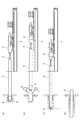
図2(a)は削孔ロッド3、補強管5及び先行下孔削孔用リングビット6による下孔削孔状態を示したもので、その下孔削孔後において、図2(b)に示すように、下孔から引き抜いた補強管5の先端に対し先行下孔削孔用リングビット6と本削孔用リングビット7が、ケーシングシュー8を介した接続により着脱可能となっている。
FIG. 2A shows a lower hole drilling state by the
従って、図2(c)に示すように、補強管5の先端に本削孔用リングビット7を、ケーシングシュー8を介した接続により取り付けることができる。この本削孔用リングビット7の中央穴からセンター削孔ビット4が僅かに突出して本削孔が行われる。
なお、本削孔用リングビット7の外形は、例えば146mm程度である。
Therefore, as shown in FIG. 2C, the
Note that the outer shape of the
図2(d)に本削孔後の状態を示す。 FIG. 2D shows a state after the main drilling.
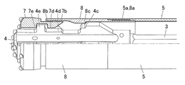
図3は本削孔用リングビット7と補強管5の接続構造を示したもので、図示のように、補強管5に対しケーシングシュー8が、補強管5の先端内周のネジ5aにケーシングシューの後端外周のネジ8aを締め込んで結合される。
そして、ケーシングシュー8に対し本削孔用リングビット7は、ケーシングシュー8の先端内周のネジ8bに本削孔用リングビット7の後端外周のネジ7bをねじ込んでから、そのネジ8bにネジ7bが通過させて、ケーシングシュー8に対し本削孔用リングビット7が自由に回転できる接続状態になっている。
FIG. 3 shows a connection structure between the
Then, the
さらに、センター削孔ビット4とケーシングシュー8とに、フィード伝達部4c・8cが設けられている。
また、センター削孔ビット4と本削孔用リングビット7とには、回転伝達部4d・7dと、打撃伝達部4e・7eが設けられている。
なお、ケーシングシュー8に対する先行下孔削孔用リングビット6の接続構造も同様である。
Further, the
The
The connection structure of the
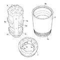
図4はセンター削孔ビット4と本削孔用リングビット7とケーシングシュー8を分解して並べたもので、図5はセンター削孔ビット4を側方から見たものである。
FIG. 4 shows the
図示のように、センター削孔ビット4の外周には、後方寄りに円周方向に沿った突状のフィード伝達部4cが形成され、前方寄りに軸線方向に沿った突状の回転伝達部4dが形成されて、その回転伝達部4dの前側に円周方向に沿った突状の打撃伝達部4eが形成されている。
ケーシングシュー8の内周には、円周方向に沿った突状のフィード伝達部8cが形成されている。
As shown in the drawing, on the outer periphery of the
On the inner periphery of the
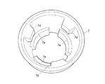
また、図6は本削孔用リングビット7を下方から見たもので、図示のように、本削孔用リングビット7の外周には、後部に軸線方向に沿った突状の回転伝達部7dが形成されて、その回転伝達部7dの前側に円周方向に沿った突状の打撃伝達部7eが形成されている。
FIG. 6 shows the main
従って、センター削孔ビット4に伝わった給進力と打撃力は打撃伝達部4e・7eから本削孔用リングビット7に伝わる。また、回転力は回転伝達部4d・7dの側面を通して伝わる。
なお、逆方向に回転すると、センター削孔ビット4の回転伝達部4dの側面から本削孔用リングビット7の回転伝達部7dが離れ、センター削孔ビット4を引き抜くことが可能となる。
Accordingly, the feeding force and the striking force transmitted to the
When rotating in the reverse direction, the
次に、図7(a)にセンター削孔ビット4の外観を示し、図7(b)に示すように、先行下孔削孔用リングビット6の中央穴からセンター削孔ビット4が僅かに突出している。
Next, FIG. 7A shows the appearance of the
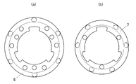
図8(a)に先行下孔削孔用リングビット6の正面視を示し、図8(b)に本削孔用リングビット7の正面視を示している。
FIG. 8A shows a front view of the preceding lower hole
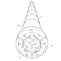
図9に補強管5に先行下孔削孔用リングビット6を取り付けた状態の外観を示している。
FIG. 9 shows the external appearance of the reinforcing
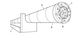
図10にガイドセル1上の補強管5に本削孔用リングビット7を取り付けた状態の外観を示している。
FIG. 10 shows the external appearance of a state where the
削孔の実施手順、及び地山補強手順は次のとおりである。
手順1.ドリルジャンボに削孔ロッド3・センター削孔ビット4・補強管5・先行下孔削孔用リングビット6を設置
手順2.センター削孔ビット4と補強管5先端に取り付けた先行下孔削孔用リングビット6による下孔の削孔(削孔長は、例えば300mm程度)
手順3.削孔ロッド3・センター削孔ビット4・補強管5・先行下孔削孔用リングビット6の引抜き(引抜き長は、例えば500mm程度)
The drilling procedure and ground reinforcement procedure are as follows.
手順4.補強管5先端の先行下孔削孔用リングビット6を本削孔用リングビット7に交換
手順5.下孔に削孔ロッド3・センター削孔ビット4・補強管5・本削孔用リングビット7を挿入
手順6.センター削孔ビット4と補強管5先端に取り付けた本削孔用リングビット7による本削孔
手順7.所定の削孔長まで削孔ロッド3・補強管5を継ぎ足して本削孔継続
手順8.削孔ロッド3・センター削孔ビット4の引抜き、本削孔用リングビット7の埋殺し
手順9.補強管5と下孔の間をシーリング
手順10.薬液注入
以上の削孔により、次の効果が得られる。
(1)高剛性の鋼管による補強管5を用いて先行下孔削孔用リングビット6で下孔を削孔するため、図1に示すように、削孔ロッド3の垂れ下がりやしなりの影響がなく、下孔を正確な位置に削孔することができる。
(2)下孔削孔後、僅かな引抜き(引抜き長、例えば500mm程度)で先行下孔削孔用リングビット6と本削孔リングビット7の交換が可能であるため、ドリルジャンボのブームを動かす必要がなく、削孔方向を調整する作業が下孔削孔セット時の1回で済み、作業時間の短縮が可能となる。
これに対し、特許文献1では下孔削孔セット時と補強管削孔セット時の2回の削孔方向の調整作業を要していた。
(3)ドリルジャンボのブームを動かす必要がないため、下孔削孔と本削孔を同一芯により削孔できることから、削孔方向の精度が向上する。
(4)従って、下孔の位置を精度よく削孔でき、補強管5の削孔方向も精度よく削孔でき、作業時間を短縮できる。
The following effects are obtained by the above drilling.
(1) Since the lower hole is drilled with the
(2) After drilling the lower hole, it is possible to replace the
On the other hand,
(3) Since it is not necessary to move the boom of the drill jumbo, the lower hole drilling and the main drilling hole can be drilled with the same core, so that the accuracy in the drilling direction is improved.
(4) Therefore, the position of the lower hole can be drilled with high precision, the drilling direction of the reinforcing
以上、実施形態の地山補強工法における先行下孔削孔方法によれば、補強管5の先端に取り付けた先行下孔削孔用リングビット6を用いて下孔を削孔することで、下孔の位置を精度よく削孔できるとともに、補強管5の削孔方向を精度よく削孔できて、作業時間を短縮することができる。
As described above, according to the preceding lower hole drilling method in the natural ground reinforcement method of the embodiment, the lower hole is drilled by using the
(変形例)
以上の実施形態の他、ビット形状や寸法は任意であり、具体的な細部手法等についても適宜に変更可能であることは勿論である。
(Modification)
In addition to the above embodiments, the bit shape and dimensions are arbitrary, and it is needless to say that specific details and the like can be changed as appropriate.
1 ガイドセル
2 削孔機
3 削孔ロッド
4 センター削孔ビット
4c フィード伝達部
4d 回転伝達部
4e 打撃伝達部
5 補強管
5a ネジ
6 先行下孔削孔用リングビット
7 本削孔用リングビット
7b ネジ
7d 回転伝達部
7e 打撃伝達部
8 ケーシングシュー
8a ネジ
8b ネジ
8c フィード伝達部
DESCRIPTION OF
Claims (4)
前記補強管の先端に取り付けた下孔削孔用ビットで前記下孔を削孔することを特徴とする地山補強工法における下孔削孔方法。 After drilling a pilot hole in a natural ground, and applying a main drilling hole having a smaller diameter than the lower hole, in the natural ground reinforcement construction method of placing a reinforcing pipe in the main drilling hole,
A lower hole drilling method in a natural ground reinforcement method, wherein the lower hole is drilled with a lower hole drilling bit attached to a tip of the reinforcing pipe.
前記補強管先端の前記下孔削孔用ビットを取り外してから、前記下孔削孔用ビットより小径の本削孔用ビットを前記補強管先端に取り付けて、
前記本削孔用ビットで前記本削孔を施すとともに、前記本削孔内に補強管を打設することを特徴とする地山補強工法。 After carrying out the preliminary drilling method in the natural ground reinforcement method according to claim 1 or 2,
After removing the lower hole drilling bit at the tip of the reinforcing pipe, a main drilling bit having a diameter smaller than that of the lower hole drilling bit is attached to the tip of the reinforcing pipe,
A ground reinforcement method, wherein the main drilling hole is formed by the main drilling bit, and a reinforcing pipe is placed in the main drilling hole.
Priority Applications (1)
| Application Number | Priority Date | Filing Date | Title |
|---|---|---|---|
| JP2016079376A JP6682137B2 (en) | 2016-04-12 | 2016-04-12 | Downhole drilling method in ground reinforcement method and ground reinforcement method |
Applications Claiming Priority (1)
| Application Number | Priority Date | Filing Date | Title |
|---|---|---|---|
| JP2016079376A JP6682137B2 (en) | 2016-04-12 | 2016-04-12 | Downhole drilling method in ground reinforcement method and ground reinforcement method |
Publications (2)
| Publication Number | Publication Date |
|---|---|
| JP2017190580A true JP2017190580A (en) | 2017-10-19 |
| JP6682137B2 JP6682137B2 (en) | 2020-04-15 |
Family
ID=60085730
Family Applications (1)
| Application Number | Title | Priority Date | Filing Date |
|---|---|---|---|
| JP2016079376A Active JP6682137B2 (en) | 2016-04-12 | 2016-04-12 | Downhole drilling method in ground reinforcement method and ground reinforcement method |
Country Status (1)
| Country | Link |
|---|---|
| JP (1) | JP6682137B2 (en) |
Cited By (2)
| Publication number | Priority date | Publication date | Assignee | Title |
|---|---|---|---|---|
| JP2022062826A (en) * | 2020-10-09 | 2022-04-21 | 東京テクノ株式会社 | Underground buried object crushing and removing device |
| JP7152088B1 (en) | 2022-05-19 | 2022-10-12 | 東邦金属株式会社 | drill bit, drilling equipment |
Citations (5)
| Publication number | Priority date | Publication date | Assignee | Title |
|---|---|---|---|---|
| JPH06294281A (en) * | 1993-04-09 | 1994-10-21 | Taisei Corp | How to place pipes for pipe roof |
| JP2002138786A (en) * | 2000-10-30 | 2002-05-17 | Hazama Gumi Ltd | Drill bit |
| WO2003001022A1 (en) * | 2001-06-26 | 2003-01-03 | Sandvik Ab; (Publ) | Rock drilling tool, a ring drill bit and an adapter for percussive drilling |
| JP2006176999A (en) * | 2004-12-21 | 2006-07-06 | Kumagai Gumi Co Ltd | Reinforcement method of natural ground |
| JP2006336282A (en) * | 2005-06-01 | 2006-12-14 | Kfc Ltd | Ground reinforcement method and bit for forming a pilot hole used therefor |
-
2016
- 2016-04-12 JP JP2016079376A patent/JP6682137B2/en active Active
Patent Citations (5)
| Publication number | Priority date | Publication date | Assignee | Title |
|---|---|---|---|---|
| JPH06294281A (en) * | 1993-04-09 | 1994-10-21 | Taisei Corp | How to place pipes for pipe roof |
| JP2002138786A (en) * | 2000-10-30 | 2002-05-17 | Hazama Gumi Ltd | Drill bit |
| WO2003001022A1 (en) * | 2001-06-26 | 2003-01-03 | Sandvik Ab; (Publ) | Rock drilling tool, a ring drill bit and an adapter for percussive drilling |
| JP2006176999A (en) * | 2004-12-21 | 2006-07-06 | Kumagai Gumi Co Ltd | Reinforcement method of natural ground |
| JP2006336282A (en) * | 2005-06-01 | 2006-12-14 | Kfc Ltd | Ground reinforcement method and bit for forming a pilot hole used therefor |
Cited By (3)
| Publication number | Priority date | Publication date | Assignee | Title |
|---|---|---|---|---|
| JP2022062826A (en) * | 2020-10-09 | 2022-04-21 | 東京テクノ株式会社 | Underground buried object crushing and removing device |
| JP7152088B1 (en) | 2022-05-19 | 2022-10-12 | 東邦金属株式会社 | drill bit, drilling equipment |
| JP2023170568A (en) * | 2022-05-19 | 2023-12-01 | 東邦金属株式会社 | Drilling bit, drilling equipment |
Also Published As
| Publication number | Publication date |
|---|---|
| JP6682137B2 (en) | 2020-04-15 |
Similar Documents
| Publication | Publication Date | Title |
|---|---|---|
| RU2007138335A (en) | EQUIPMENT AND METHOD FOR CREATING MICRO-SUPPORTS IN SOIL, INTENDED, IN PARTICULAR, FOR ATTACHING ACTIVE ANCHORS | |
| AU726332B2 (en) | Process and device for simultaneously drilling and lining a hole | |
| CN105863512A (en) | Coal mine underground broken soft coal seam ladder pipe-tracing compound directional drilling pore-forming device and method | |
| KR20080053466A (en) | Impact Hammer for Excavator Expansion | |
| SG10201900473TA (en) | Drilling device for earth or rock drilling and method for retrofitting such a drilling device | |
| JP2019065536A (en) | Lock bolt installation device and lock bolt installation method | |
| JP2017190580A (en) | Pre-drilling method in natural ground reinforcement method and natural ground reinforcement method | |
| JP6307002B2 (en) | Ground drilling method and ground drilling device | |
| SE0202592D0 (en) | Method and apparatus for directional drilling under mixed conditions | |
| CN208203163U (en) | A kind of drill rod centering device for Drilling trolley drilling construction | |
| JPH09250287A (en) | Ground drilling device | |
| US4100972A (en) | Displacement hammer apparatus for sinking and lining boreholes | |
| WO2012101433A3 (en) | Drilling device for percussion or rotary percussion drilling having a coupling sleeve | |
| JP5543885B2 (en) | Bent boring method and drilling device used therefor | |
| FI20060749A7 (en) | Drilling tool for drilling or reaming a hole | |
| JP2016098484A (en) | Reinforcing pipe connecting device and connecting method | |
| JP6389681B2 (en) | Ground improvement method in front of face in tunnel excavation work. | |
| JP4249107B2 (en) | Rod-shaped member feeding device | |
| JP2000337079A (en) | Double pipe type drilling method, device therefor, and buried pipe pushing adapter | |
| JP2009507154A (en) | Single member drill bit and single pass drilling device for single pass anchor bolt fastening | |
| KR20190027580A (en) | Boring apparatus with linear multi core-drill and method for securing free surface usinf the same | |
| KR102160327B1 (en) | Method for putting together a down-the-hole drilling apparatus for plastic pipe drilling and a down-the-hole drilling apparatus | |
| CN209430235U (en) | Wall Rock of Tunnel bracing means under a kind of complex geological condition | |
| JP2004232304A (en) | Single push free propulsion tool, single push propulsion method and pipe laying method | |
| JP2021067008A (en) | Auxiliary construction method |
Legal Events
| Date | Code | Title | Description |
|---|---|---|---|
| A621 | Written request for application examination |
Free format text: JAPANESE INTERMEDIATE CODE: A621 Effective date: 20190220 |
|
| A977 | Report on retrieval |
Free format text: JAPANESE INTERMEDIATE CODE: A971007 Effective date: 20191120 |
|
| A131 | Notification of reasons for refusal |
Free format text: JAPANESE INTERMEDIATE CODE: A131 Effective date: 20191126 |
|
| A521 | Request for written amendment filed |
Free format text: JAPANESE INTERMEDIATE CODE: A523 Effective date: 20200110 |
|
| TRDD | Decision of grant or rejection written | ||
| A01 | Written decision to grant a patent or to grant a registration (utility model) |
Free format text: JAPANESE INTERMEDIATE CODE: A01 Effective date: 20200324 |
|
| A61 | First payment of annual fees (during grant procedure) |
Free format text: JAPANESE INTERMEDIATE CODE: A61 Effective date: 20200324 |
|
| R150 | Certificate of patent or registration of utility model |
Ref document number: 6682137 Country of ref document: JP Free format text: JAPANESE INTERMEDIATE CODE: R150 |
|
| R250 | Receipt of annual fees |
Free format text: JAPANESE INTERMEDIATE CODE: R250 |
|
| R250 | Receipt of annual fees |
Free format text: JAPANESE INTERMEDIATE CODE: R250 |