JP2017190629A - Joint structure of precast member - Google Patents
Joint structure of precast member Download PDFInfo
- Publication number
- JP2017190629A JP2017190629A JP2016081181A JP2016081181A JP2017190629A JP 2017190629 A JP2017190629 A JP 2017190629A JP 2016081181 A JP2016081181 A JP 2016081181A JP 2016081181 A JP2016081181 A JP 2016081181A JP 2017190629 A JP2017190629 A JP 2017190629A
- Authority
- JP
- Japan
- Prior art keywords
- precast
- main
- joining
- plate
- concrete
- Prior art date
- Legal status (The legal status is an assumption and is not a legal conclusion. Google has not performed a legal analysis and makes no representation as to the accuracy of the status listed.)
- Granted
Links
Images
Landscapes
- Joining Of Building Structures In Genera (AREA)
Abstract
【課題】プレキャスト部材と他のコンクリート部材との間隔を小さくするとともに、施工の手間を低減することができるプレキャスト部材の接合構造を提供する。【解決手段】プレキャスト部材を他のコンクリート部材に接合するための接合構造である。プレキャスト部材の接合端面と、他のコンクリート部材の接合端面との間には充填材が充填されている。プレキャスト部材および他のコンクリート部材の両主筋20,30において、第二主筋30の先端部にプレート70が接合されるとともに、第一主筋20の先端部に筒状部材80が接合されている。筒状部材80の周壁部には開口部82が形成されている。開口部82に第二主筋30が挿通され、プレート70が筒状部材80内に配置されている。【選択図】図1PROBLEM TO BE SOLVED: To provide a joint structure of a precast member capable of reducing the distance between the precast member and another concrete member and reducing the labor of construction. SOLUTION: This is a joining structure for joining a precast member to another concrete member. A filler is filled between the joint end face of the precast member and the joint end face of another concrete member. In both main bars 20 and 30 of the precast member and other concrete members, the plate 70 is joined to the tip of the second main bar 30, and the tubular member 80 is joined to the tip of the first main bar 20. An opening 82 is formed in the peripheral wall portion of the tubular member 80. The second main bar 30 is inserted through the opening 82, and the plate 70 is arranged in the tubular member 80. [Selection diagram] Fig. 1
Description
本発明は、プレキャスト部材を他のコンクリート部材に接合するための接合構造に関する。 The present invention relates to a joining structure for joining a precast member to another concrete member.
ビルなどの構造物を建築する場合に、工場で予め製作されたコンクリート製のプレキャスト部材を現場に搬入し、プレキャスト部材を他のコンクリート部材(例えば、既設のコンクリート部材や他のプレキャスト部材)に接合することで、床版や梁を構築する工法が用いられている。 When building a structure such as a building, a concrete precast member manufactured in advance at the factory is brought into the field, and the precast member is joined to another concrete member (for example, an existing concrete member or another precast member). By doing so, construction methods for building floor slabs and beams are used.
プレキャスト部材を他のコンクリート部材に接合するための接合構造としては、プレキャスト部材および他のコンクリート部材から主筋を突出させた状態で、プレキャスト部材と他のコンクリート部材とを間隔を空けて配置し、プレキャスト部材と他のコンクリート部材との間にグラウトを充填しているものがある。 As a joining structure for joining a precast member to another concrete member, the precast member and the other concrete member are arranged with a space in a state where the main bars protrude from the precast member and the other concrete member. There is one in which grout is filled between a member and another concrete member.
前記した接合構造では、プレキャスト部材の主筋と、他のコンクリート部材の主筋とを重ねて配置する重ね継手を用いる場合がある(例えば、特許文献1参照)。
また、前記した接合構造では、プレキャスト部材の主筋と、他のコンクリート部材の主筋とをパイプの両端に挿入する機械式継手を用いる場合がある(例えば、特許文献2参照)。
In the above-described joint structure, a lap joint in which the main bars of the precast member and the main bars of the other concrete member are arranged in an overlapping manner may be used (for example, see Patent Document 1).
Moreover, in the above-described joining structure, a mechanical joint that inserts the main reinforcement of the precast member and the main reinforcement of the other concrete member into both ends of the pipe may be used (for example, see Patent Document 2).
前記した重ね継手では、両主筋の先端部同士を大きく重ね合わせる必要がある。また、機械式継手では、パイプと主筋との重ね代を確保する必要がある。このように、重ね継手および機械式継手では、プレキャスト部材と他のコンクリート部材との間隔が大きくなるため、接合端面からの主筋の突出量が大きくなる。
したがって、重ね継手または機械式継手を用いた接合構造では、グラウトの充填量や主筋の量が多くなり、施工コストが高くなるという問題がある。
In the lap joint described above, it is necessary to largely overlap the tip portions of both main bars. Moreover, in a mechanical joint, it is necessary to ensure the allowance for a pipe and a main reinforcement. As described above, in the lap joint and the mechanical joint, the distance between the precast member and the other concrete member is increased, so that the protrusion amount of the main bar from the joint end surface is increased.
Therefore, in a joining structure using a lap joint or a mechanical joint, there is a problem that the amount of grout filling and the amount of main bars increase, and the construction cost increases.
さらに、機械式継手では、パイプの両端に主筋を挿入する作業が煩雑であるため、施工期間が長くなるという問題がある。 Furthermore, in the mechanical joint, there is a problem that the construction period becomes long because the operation of inserting the main bars at both ends of the pipe is complicated.
本発明は、前記した問題を解決し、プレキャスト部材と他のコンクリート部材との間隔を小さくするとともに、施工の手間を低減することができるプレキャスト部材の接合構造を提供することを課題とする。 This invention solves an above-described problem, and makes it a subject to provide the joining structure of the precast member which can reduce the effort of construction while reducing the space | interval of a precast member and another concrete member.
前記課題を解決するため、本発明は、プレキャスト部材を他のコンクリート部材に接合するための接合構造である。前記プレキャスト部材の接合端面と、前記他のコンクリート部材の接合端面との間に充填材が充填されている。前記プレキャスト部材および前記他のコンクリート部材の両主筋において、一方の前記主筋の先端部にプレートが接合されるとともに、他方の前記主筋の先端部に筒状部材が接合されている。前記筒状部材の周壁部には、開口縁部から延びている開口部が形成されており、前記開口部に一方の前記主筋が挿通され、前記プレートが前記筒状部材内に配置されている。
なお、本発明において、プレキャスト部材の接合端面と、他のコンクリート部材の接合端面とを間隔を空けて配置した場合には、両接合端面の間の空間に充填材を充填する。また、プレキャスト部材の接合端面と、他のコンクリート部材の接合端面とを密着させた場合には、両接合端面の間に配置された筒状部材内の空間に充填材を充填する。
In order to solve the above problems, the present invention is a joint structure for joining a precast member to another concrete member. A filler is filled between the joint end surface of the precast member and the joint end surface of the other concrete member. In both main bars of the precast member and the other concrete member, a plate is joined to the tip of one of the main bars, and a tubular member is joined to the tip of the other main bar. An opening extending from an opening edge is formed in the peripheral wall portion of the cylindrical member, one of the main bars is inserted into the opening, and the plate is disposed in the cylindrical member. .
In the present invention, when the joint end face of the precast member and the joint end face of the other concrete member are arranged with a space therebetween, the space between the joint end faces is filled with the filler. Further, when the joining end face of the precast member and the joining end face of another concrete member are brought into close contact with each other, the space in the cylindrical member disposed between the joining end faces is filled with the filler.
本発明の接合構造では、両主筋の先端部に接合されたプレートおよび筒状部材を組み合わせることで、充填材への主筋の定着性能を確保することができる。これにより、本発明の接合構造では、接合端面からの主筋の突出量を小さくすることができ、プレキャスト部材と他のコンクリート部材との間隔を小さくすることができるため、充填材を減らすことができる。 In the joining structure of the present invention, the fixing performance of the main bars to the filler can be ensured by combining the plate and the cylindrical member joined to the tip portions of both main bars. Thereby, in the joining structure of this invention, since the protrusion amount of the main reinforcement from a joining end surface can be made small and the space | interval of a precast member and another concrete member can be made small, a filler can be reduced. .
本発明の接合構造では、一方の主筋のプレートが筒状部材に囲まれているため、両主筋の間で応力を効率良く伝達することができる。 In the joint structure of the present invention, since the plate of one main bar is surrounded by the cylindrical member, stress can be efficiently transmitted between both main bars.
本発明の接合構造では、他方の主筋に設けられた筒状部材の開口部に対して、一方の主筋を側方から入り込ませることで、プレートを筒状部材内に挿入することができる。 In the joining structure of the present invention, the plate can be inserted into the cylindrical member by allowing one of the main bars to enter from the side of the opening of the cylindrical member provided on the other main bar.
本発明の接合構造において、プレキャスト部材と他のコンクリート部材との間に複数の主筋、プレートおよび筒状部材を組み合わせて配置した場合には、プレキャスト部材と他のコンクリート部材との間に充填材を充填することで、複数の主筋、プレートおよび筒状部材を一括してグラウトに定着させることができる。 In the joint structure of the present invention, when a plurality of main bars, plates, and cylindrical members are arranged in combination between the precast member and the other concrete member, a filler is provided between the precast member and the other concrete member. By filling, a plurality of main bars, plates and cylindrical members can be fixed to the grout at once.
前記した本発明の接合構造において、前記筒状部材を前記プレキャスト部材または前記他のコンクリート部材の内部に入り込ませた場合には、プレキャスト部材と他のコンクリート部材との間隔をより小さくすることができる。 In the joint structure of the present invention described above, when the cylindrical member is inserted into the precast member or the other concrete member, the interval between the precast member and the other concrete member can be further reduced. .
本発明の接合構造では、主筋の量を減らすとともに、プレキャスト部材と他のコンクリート部材との間に充填する充填材を減らすことができるため、施工コストを低減することができる。
本発明の接合構造では、一方の主筋のプレートが筒状部材に囲まれているため、両主筋の間で応力を効率良く伝達することができる。
本発明の接合構造では、筒状部材の開口部に対して、一方の主筋を側方から入り込ませることで、プレートと筒状部材とを簡単に組み合わせることができるため、施工期間を短くすることができる。
In the joining structure of the present invention, the amount of main bars can be reduced, and the filler filled between the precast member and the other concrete member can be reduced, so that the construction cost can be reduced.
In the joint structure of the present invention, since the plate of one main bar is surrounded by the cylindrical member, stress can be efficiently transmitted between both main bars.
In the joint structure of the present invention, the plate and the cylindrical member can be easily combined by allowing one main bar to enter from the side of the opening of the cylindrical member, thereby shortening the construction period. Can do.
本発明の実施形態について、適宜図面を参照しながら詳細に説明する。
以下の説明において、前後左右方向とは、実施形態の接合構造を説明する上で便宜上設定したものであり、接合構造を構成する各部材の配置や向きを限定するものではない。
Embodiments of the present invention will be described in detail with reference to the drawings as appropriate.
In the following description, the front, rear, left, and right directions are set for convenience in describing the joint structure of the embodiment, and do not limit the arrangement and orientation of each member constituting the joint structure.
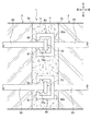
本実施形態の接合構造1は、図2に示すように、プレキャスト部材3をコンクリート部材2(特許請求の範囲における「他のコンクリート部材」)に接合するための構造である。本実施形態のプレキャスト部材3およびコンクリート部材2は、構造物の床版を構成するものである。
本実施形態では、コンクリート部材2の接合端面2aの前方にプレキャスト部材3の接合端面3aが配置されている。このように、プレキャスト部材3の接合端面3aと、コンクリート部材2の接合端面2bとは、前後方向(主筋20,30の延長方向)に間隔を空けて配置されており、両接合端面2a,3aの間に接合空間4が形成されている。
The joining
In the present embodiment, the
本実施形態のコンクリート部材2は、工場で予め製作された鉄筋コンクリート製のプレキャスト部材である。なお、施工現場においてコンクリートを打設して、コンクリート部材2を構築してもよい。
コンクリート部材2には、複数の第一主筋20が軸方向(前後方向)に配筋されている。第一主筋20は、異形鉄筋であり、コンクリート部材2の接合端面2aから前方に向けて突出している。第一主筋20の先端部は、接合空間4内に配置されている。
The
The
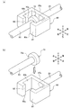
第一主筋20の先端部には、図1(b)に示すように、筒状部材80が接合されている。筒状部材80は、前後左右の壁部が形成された鋼製の角筒状の部材であり、上面および下面が開口している。本実施形態の筒状部材80は、溝形鋼を用いて形成されている。
図2に示すように、筒状部材80の後面80aの中央部には、第一主筋20の先端面が溶接または摩擦圧接により接合されている。第一主筋20は、筒状部材80の後面80aに対して垂直に配置されている。
なお、筒状部材80と第一主筋20との接続方法は限定されるものではなく、例えば、筒状部材80の後面80aにねじ穴を形成したり、後面80aにナットを溶接したりするとともに、第一主筋20の先端部に雄ねじを形成し、筒状部材80に第一主筋20の先端部を螺合させてもよい。
As shown in FIG. 1B, a
As shown in FIG. 2, the front end surface of the first
In addition, the connection method of the
筒状部材80の前壁81には、図1(b)に示すように、上側の開口縁部80bから下側の開口縁部80cに亘って直線状の開口部82が形成されている。
このように、筒状部材80の周壁部の前部は、上下方向に延びている開口部82によって切り開かれている。開口部82の左右方向の幅は、後記する第二主筋30の直径よりも大きく形成されている。
As shown in FIG. 1B, a
Thus, the front part of the peripheral wall part of the
プレキャスト部材3は、図2に示すように、工場で予め製作された鉄筋コンクリート製のプレキャスト部材である。
プレキャスト部材3には、コンクリート部材2と同様に、複数の第二主筋30が配筋されている。第二主筋30は、プレキャスト部材3の接合端面3aから後方に向けて突出しており、第二主筋30の先端部は接合空間4内に配置されている。
As shown in FIG. 2, the
Similar to the
第二主筋30の先端部には、図1(b)に示すように、プレート70が接合されている。プレート70は、円板状の鋼板である。
図2に示すように、プレート70の前面70a(プレキャスト部材3側の面)の中心部に第二主筋30の先端面が溶接または摩擦圧接により接合されている。第二主筋30は、プレート70の前面70aに対して垂直に配置されている。
なお、プレート70と第二主筋30との接続方法は限定されるものではなく、例えば、プレート70の前面70aにねじ穴を形成したり、前面70aにナットを溶接したりするとともに、第二主筋30の先端部に雄ねじを形成し、プレート70に第二主筋30の先端部を螺合させてもよい。
As shown in FIG. 1B, a
As shown in FIG. 2, the front end surface of the second main reinforcing
In addition, the connection method of the
第二主筋30は、筒状部材80の開口部82に対して前後方向に挿通されている。そして、第二主筋30の先端部に接合されたプレート70は、筒状部材80内に配置されており、プレート70は、筒状部材80の周壁部に囲まれている(図1(a)参照)。
The second
接合空間4には、グラウトG(特許請求の範囲における「充填材」)が充填されている。本実施形態のグラウトGは、セメント系のモルタルである。なお、グラウトG(充填材)には、繊維などの補強材を入れたり、膨張材などの混和材を添加したりしてもよく、グラウトGの配合は限定されるものではない。
グラウトGによって接合空間4全体が埋められている。したがって、両主筋20,30の先端部、プレート70および筒状部材80もグラウトG内に埋められている。さらに、グラウトGは筒状部材80内にも充填されている。
The
The entire
次に、本実施形態の接合構造1を構築する手順について説明する。
まず、図2に示すように、コンクリート部材2の接合端面2aの前方にプレキャスト部材3を移動させ、プレキャスト部材3の接合端面3aとコンクリート部材2の接合端面2aとを前後方向に間隔を空けて配置する。
Next, a procedure for constructing the
First, as shown in FIG. 2, the
このとき、本実施形態では、プレキャスト部材3をコンクリート部材2の上方から下方に向けて移動させる。このようにすると、図1(b)に示すように、第二主筋30およびプレート70が、筒状部材80に対して上方から近づくことになる。
これにより、図1(a)に示すように、筒状部材80の開口部82に第二主筋30が入り込むとともに、筒状部材80内にプレート70が入り込む。
At this time, in the present embodiment, the
Thereby, as shown in FIG. 1A, the second
このようにして、プレート70と筒状部材80とを組み合わせた後に、図2に示すように、接合空間4にグラウトGを充填する。
接合空間4内でグラウトGが硬化すると、両主筋20,30、プレート70および筒状部材80がグラウトGに定着し、プレキャスト部材3がコンクリート部材2に接合される。
Thus, after combining the
When the grout G is hardened in the joining
以上のような本実施形態の接合構造1では、図2に示すように、両主筋20,30の先端部に接合されたプレート70および筒状部材80を組み合わせることで、グラウトGへの両主筋20,30の定着性能を確保することができる。
これにより、本実施形態の接合構造1では、両接合端面2a,3aからの両主筋20,30の突出量を小さくすることができる。したがって、プレキャスト部材3とコンクリート部材2との間の接合空間4を小さくすることができ、接合空間4に充填するグラウトGを減らすことができる。
このように、本実施形態の接合構造1では、主筋20,30の量を減らすとともに、接合空間4に充填するグラウトGを減らすことができるため、施工コストを低減することができる。
In the joining
Thereby, in the joining
Thus, in the joining
本実施形態の接合構造1では、図1(a)に示すように、第二主筋30のプレート70が第一主筋20の筒状部材80に囲まれているため、両主筋20,30の間で応力を効率良く伝達することができる。
In the joining
本実施形態の接合構造1を構築するときには、図1(b)に示すように、第二主筋30およびプレート70を上方から筒状部材80に向けて移動させることで、第二主筋30を筒状部材80の開口部82に挿入するとともに、プレート70を筒状部材80内に挿入することができる。このように、プレート70と筒状部材80とを簡単に組み合わせることができるため、施工期間を短くすることができる。
When constructing the
本実施形態の接合構造1では、図2に示すように、接合空間4に複数の主筋20,30、プレート70および筒状部材80が配置されている場合でも、接合空間4にグラウトGを充填することで、複数の主筋20,30、プレート70および筒状部材80を一括してグラウトGに定着することができる。
In the joining
以上、本発明の実施形態について説明したが、本発明は前記実施形態に限定されることなく、その趣旨を逸脱しない範囲で適宜に変更が可能である。
本実施形態では、図1(b)に示すように、第二主筋30にプレート70を設け、第一主筋20に筒状部材80を設けているが、第一主筋20にプレート70を設け、第二主筋30に筒状部材80を設けてもよい。
The embodiment of the present invention has been described above, but the present invention is not limited to the above-described embodiment, and can be appropriately changed without departing from the spirit of the present invention.
In this embodiment, as shown in FIG.1 (b), the
本実施形態の筒状部材80では、上側の開口縁部80bから下側の開口縁部80cに亘って開口部82が形成されているが、上側の開口縁部80bまたは下側の開口縁部80cから上下方向に延びている凹状の開口部を形成してもよい。
In the
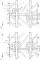
本実施形態の接合構造1では、図2に示すように、筒状部材80が接合空間4内に配置されているが、図3(a)に示すように、筒状部材80をコンクリート部材2内に入り込ませてもよい。
この構成では、筒状部材80の前面を接合端面2aに露出させており、開口部82が接合端面2aに開口している。このように、筒状部材80の少なくとも一部をコンクリート部材2内に入り込ませると、接合空間4をより小さくすることができる。
In the joining
In this configuration, the front surface of the
なお、プレキャスト部材3の第二主筋30に筒状部材80が接合されている場合には、筒状部材80をプレキャスト部材3内に入り込ませてもよい。
さらに、図3(b)に示すように、第一主筋20に接合させた筒状部材80は、他のコンクリート部材2に入り込ませ、第二主筋30に接合させた筒状部材80は、プレキャスト部材3に入り込ませてもよい。
In addition, when the
Furthermore, as shown in FIG. 3 (b), the
本実施形態の接合構造1では、図2に示すように、プレキャスト部材3の接合端面3aと、コンクリート部材2の接合端面2aとが間隔を空けて配置されている。しかしながら、図3(a)および(b)に示す接合構造1において、プレキャスト部材3の接合端面3aと、コンクリート部材2の接合端面2aとを接着材によって密着させた場合には、両接合端面2a,3aの間に配置された筒状部材80内の空間にグラウトGを充填することになる。
In the joining
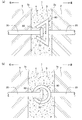
本実施形態の筒状部材80は、図2に示すように、角筒状に形成されているが、その形状は限定されるものではない。例えば、図4(a)に示すように、筒状部材80を平面視で三角形の筒状に形成してもよい。さらに、図4(b)に示すように、筒状部材80を円筒状に形成してもよい。
As shown in FIG. 2, the
本実施形態のプレート70は、図1(b)に示すように、円形に形成されているが、プレート70の形状は限定されるものではなく、例えば、多角形、長円形、楕円形などの形状に形成することもできる。
The
1 接合構造
2 コンクリート部材
2a 接合端面
3 プレキャスト部材
3a 接合端面
4 接合空間
20 第一主筋
30 第二主筋
70 プレート
70a 前面
80 筒状部材
80a 後面
80b 上側の開口縁部
80c 下側の開口縁部
81 前壁
82 開口部
G グラウト(充填材)
DESCRIPTION OF
Claims (2)
前記プレキャスト部材の接合端面と、前記他のコンクリート部材の接合端面との間に充填材が充填されており、
前記プレキャスト部材および前記他のコンクリート部材の両主筋において、
一方の前記主筋の先端部にプレートが接合されるとともに、
他方の前記主筋の先端部に筒状部材が接合されており、
前記筒状部材の周壁部には、開口縁部から延びている開口部が形成され、
前記開口部に一方の前記主筋が挿通され、前記プレートが前記筒状部材内に配置されて
いることを特徴とするプレキャスト部材の接合構造。 A joining structure for joining a precast member to another concrete member,
A filler is filled between the joint end surface of the precast member and the joint end surface of the other concrete member,
In both main bars of the precast member and the other concrete member,
While a plate is joined to the tip of one of the main muscles,
A cylindrical member is joined to the tip of the other main muscle,
An opening extending from the opening edge is formed in the peripheral wall of the cylindrical member,
One of the main bars is inserted into the opening, and the plate is disposed in the cylindrical member.
前記筒状部材は、前記プレキャスト部材または前記他のコンクリート部材の内部に入り込んでいることを特徴とするプレキャスト部材の接合構造。 The precast member joining structure according to claim 1,
The precast member joining structure, wherein the tubular member is inserted into the precast member or the other concrete member.
Priority Applications (1)
| Application Number | Priority Date | Filing Date | Title |
|---|---|---|---|
| JP2016081181A JP6861472B2 (en) | 2016-04-14 | 2016-04-14 | Joint structure of precast members |
Applications Claiming Priority (1)
| Application Number | Priority Date | Filing Date | Title |
|---|---|---|---|
| JP2016081181A JP6861472B2 (en) | 2016-04-14 | 2016-04-14 | Joint structure of precast members |
Publications (2)
| Publication Number | Publication Date |
|---|---|
| JP2017190629A true JP2017190629A (en) | 2017-10-19 |
| JP6861472B2 JP6861472B2 (en) | 2021-04-21 |
Family
ID=60084667
Family Applications (1)
| Application Number | Title | Priority Date | Filing Date |
|---|---|---|---|
| JP2016081181A Active JP6861472B2 (en) | 2016-04-14 | 2016-04-14 | Joint structure of precast members |
Country Status (1)
| Country | Link |
|---|---|
| JP (1) | JP6861472B2 (en) |
Cited By (4)
| Publication number | Priority date | Publication date | Assignee | Title |
|---|---|---|---|---|
| JP2020176372A (en) * | 2019-04-15 | 2020-10-29 | 戸田建設株式会社 | Joint structure of concrete precast floor slab |
| JP2020193481A (en) * | 2019-05-28 | 2020-12-03 | 戸田建設株式会社 | Joint structure of concrete precast floor slab and joint structure of concrete precast member |
| JP2021172974A (en) * | 2020-04-20 | 2021-11-01 | 株式会社安藤・間 | How to build a joint structure of precast concrete slab members and a concrete plate-like structure |
| CN115627846A (en) * | 2022-11-08 | 2023-01-20 | 中交一公局集团有限公司 | Construction method of assembled laminated slab and post-cast strip structure |
Citations (5)
| Publication number | Priority date | Publication date | Assignee | Title |
|---|---|---|---|---|
| JP2009235850A (en) * | 2008-03-28 | 2009-10-15 | Toda Constr Co Ltd | Joint structure of precast concrete member |
| JP2011063984A (en) * | 2009-09-17 | 2011-03-31 | Toda Constr Co Ltd | Concrete joint structure |
| EP2559817A2 (en) * | 2011-08-16 | 2013-02-20 | Prefabricados Dinescon, S.L. | Adjustable system for embedded union of prefabricated concrete elements for building structures, and method for performing the union of prefabricated concrete elements |
| JP2013213345A (en) * | 2012-04-02 | 2013-10-17 | Taisei Corp | Closure-type shear reinforcement member |
| CN104674946A (en) * | 2014-12-31 | 2015-06-03 | 王睿敏 | Connecting adjusting member for concrete prefabricated members and application thereof |
-
2016
- 2016-04-14 JP JP2016081181A patent/JP6861472B2/en active Active
Patent Citations (5)
| Publication number | Priority date | Publication date | Assignee | Title |
|---|---|---|---|---|
| JP2009235850A (en) * | 2008-03-28 | 2009-10-15 | Toda Constr Co Ltd | Joint structure of precast concrete member |
| JP2011063984A (en) * | 2009-09-17 | 2011-03-31 | Toda Constr Co Ltd | Concrete joint structure |
| EP2559817A2 (en) * | 2011-08-16 | 2013-02-20 | Prefabricados Dinescon, S.L. | Adjustable system for embedded union of prefabricated concrete elements for building structures, and method for performing the union of prefabricated concrete elements |
| JP2013213345A (en) * | 2012-04-02 | 2013-10-17 | Taisei Corp | Closure-type shear reinforcement member |
| CN104674946A (en) * | 2014-12-31 | 2015-06-03 | 王睿敏 | Connecting adjusting member for concrete prefabricated members and application thereof |
Cited By (8)
| Publication number | Priority date | Publication date | Assignee | Title |
|---|---|---|---|---|
| JP2020176372A (en) * | 2019-04-15 | 2020-10-29 | 戸田建設株式会社 | Joint structure of concrete precast floor slab |
| JP7215680B2 (en) | 2019-04-15 | 2023-01-31 | 戸田建設株式会社 | Joint structure of concrete precast floor slab |
| JP2020193481A (en) * | 2019-05-28 | 2020-12-03 | 戸田建設株式会社 | Joint structure of concrete precast floor slab and joint structure of concrete precast member |
| JP7254289B2 (en) | 2019-05-28 | 2023-04-10 | 戸田建設株式会社 | Joint structure of concrete precast floor slabs and joint structure of concrete precast members |
| JP2021172974A (en) * | 2020-04-20 | 2021-11-01 | 株式会社安藤・間 | How to build a joint structure of precast concrete slab members and a concrete plate-like structure |
| JP7482587B2 (en) | 2020-04-20 | 2024-05-14 | 株式会社安藤・間 | Joint structure of precast concrete slab members and method for constructing concrete slab structure |
| CN115627846A (en) * | 2022-11-08 | 2023-01-20 | 中交一公局集团有限公司 | Construction method of assembled laminated slab and post-cast strip structure |
| CN115627846B (en) * | 2022-11-08 | 2023-07-14 | 中交一公局集团有限公司 | Construction method and post-cast belt structure of a prefabricated laminated slab |
Also Published As
| Publication number | Publication date |
|---|---|
| JP6861472B2 (en) | 2021-04-21 |
Similar Documents
| Publication | Publication Date | Title |
|---|---|---|
| JP5860576B2 (en) | Precast column beam connection structure | |
| JP2012046960A (en) | Joining structure for precast concrete member and structural body | |
| JP2014055517A (en) | Precast beam-column joint structure | |
| JP6861472B2 (en) | Joint structure of precast members | |
| JP2021071026A (en) | Column-beam joint structure | |
| JP2017133277A (en) | Column beam joining structure and column beam joining method | |
| JP2019152058A (en) | Deck plate with rebar truss and floor slab structure | |
| JP6428027B2 (en) | Column rebar connection panel and rebar structure | |
| JP7087260B2 (en) | Column-beam joint structure | |
| JP2015229855A (en) | Precast beam-column joint structure | |
| JP7005877B2 (en) | Column-beam joint structure | |
| JP2020097841A (en) | Joint structure of underground wall | |
| JP4447632B2 (en) | Beam and beam-column joint structure and method of joining the same | |
| JP2019082005A (en) | Beam-to-column connection structure and construction method thereof | |
| JP6836105B2 (en) | Joint structure of precast members | |
| JP6327649B2 (en) | Concrete member joint structure and spiral reinforcement for concrete member joint structure | |
| JP5008522B2 (en) | Precast concrete member joint structure, building, and building construction method | |
| JP2008144431A (en) | Method and structure for joining precast reinforced concrete beam members | |
| JP2009108500A (en) | Precast beam construction method, precast beam, precast beam joint structure, and building | |
| JP2020073775A (en) | Junction structure of structural body | |
| JP2008069564A (en) | Method of and structure for joining precast reinforced concrete beam members together | |
| JP2006200270A (en) | Joining structure and joining method | |
| JP7158997B2 (en) | Joining structure and joining method of precast concrete members | |
| JP2018150754A (en) | Precast concrete plate joining structure and precast concrete plate joining method | |
| JP2009293347A (en) | Precast-concrete wall panel and its junction method |
Legal Events
| Date | Code | Title | Description |
|---|---|---|---|
| A521 | Request for written amendment filed |
Free format text: JAPANESE INTERMEDIATE CODE: A523 Effective date: 20160603 |
|
| A621 | Written request for application examination |
Free format text: JAPANESE INTERMEDIATE CODE: A621 Effective date: 20190313 |
|
| A521 | Request for written amendment filed |
Free format text: JAPANESE INTERMEDIATE CODE: A821 Effective date: 20190313 |
|
| A977 | Report on retrieval |
Free format text: JAPANESE INTERMEDIATE CODE: A971007 Effective date: 20200120 |
|
| A131 | Notification of reasons for refusal |
Free format text: JAPANESE INTERMEDIATE CODE: A131 Effective date: 20200218 |
|
| A521 | Request for written amendment filed |
Free format text: JAPANESE INTERMEDIATE CODE: A523 Effective date: 20200325 |
|
| A131 | Notification of reasons for refusal |
Free format text: JAPANESE INTERMEDIATE CODE: A131 Effective date: 20200908 |
|
| A521 | Request for written amendment filed |
Free format text: JAPANESE INTERMEDIATE CODE: A523 Effective date: 20201106 |
|
| A711 | Notification of change in applicant |
Free format text: JAPANESE INTERMEDIATE CODE: A711 Effective date: 20201223 |
|
| A521 | Request for written amendment filed |
Free format text: JAPANESE INTERMEDIATE CODE: A821 Effective date: 20201223 |
|
| TRDD | Decision of grant or rejection written | ||
| A01 | Written decision to grant a patent or to grant a registration (utility model) |
Free format text: JAPANESE INTERMEDIATE CODE: A01 Effective date: 20210323 |
|
| A61 | First payment of annual fees (during grant procedure) |
Free format text: JAPANESE INTERMEDIATE CODE: A61 Effective date: 20210330 |
|
| R150 | Certificate of patent or registration of utility model |
Ref document number: 6861472 Country of ref document: JP Free format text: JAPANESE INTERMEDIATE CODE: R150 |