JP2017190761A - Internal combustion engine - Google Patents
Internal combustion engine Download PDFInfo
- Publication number
- JP2017190761A JP2017190761A JP2016082092A JP2016082092A JP2017190761A JP 2017190761 A JP2017190761 A JP 2017190761A JP 2016082092 A JP2016082092 A JP 2016082092A JP 2016082092 A JP2016082092 A JP 2016082092A JP 2017190761 A JP2017190761 A JP 2017190761A
- Authority
- JP
- Japan
- Prior art keywords
- case
- oil pan
- cylinder block
- oil
- chain
- Prior art date
- Legal status (The legal status is an assumption and is not a legal conclusion. Google has not performed a legal analysis and makes no representation as to the accuracy of the status listed.)
- Pending
Links
Images
Landscapes
- Lubrication Details And Ventilation Of Internal Combustion Engines (AREA)
- Cylinder Crankcases Of Internal Combustion Engines (AREA)
Abstract
【課題】トランスミッションケースの振動に起因して、オイルパンとシリンダブロックとの取り付け部分やオイルパンとチェーンケースとの取り付け部分に過度な負担がかかることを抑制する。【解決手段】オイルパン20における上部ケース21の内部には、シリンダブロック11に固定されたエンジン部品としてのオイルポンプ40が配置されている。チェーンケース30のリアケース31には、チェーン室R側からボルトB2が挿通され、そのボルトB2がオイルポンプ40のポンプハウジング41に螺合されている。すなわち、オイルポンプ40とチェーンケース30とが連結されている。オイルパン20における上部ケース21の補強リブ25とオイルポンプ40のステー部材44とは、バランサ装置45を介して連結されている。すなわち、オイルパン20とオイルポンプ40とが連結されている。【選択図】図1An object of the present invention is to prevent an excessive load from being applied to an attachment portion between an oil pan and a cylinder block and an attachment portion between an oil pan and a chain case due to vibration of a transmission case. An oil pump 40 as an engine component fixed to a cylinder block 11 is disposed inside an upper case 21 in an oil pan 20. A bolt B2 is inserted into the rear case 31 of the chain case 30 from the chain chamber R side, and the bolt B2 is screwed into the pump housing 41 of the oil pump 40. That is, the oil pump 40 and the chain case 30 are connected. The reinforcing rib 25 of the upper case 21 in the oil pan 20 and the stay member 44 of the oil pump 40 are connected via a balancer device 45. That is, the oil pan 20 and the oil pump 40 are connected. [Selection] Figure 1
Description
本発明は、シリンダブロックの下部にオイルパンが取り付けられた内燃機関に関する。 The present invention relates to an internal combustion engine in which an oil pan is attached to a lower portion of a cylinder block.
特許文献1に記載の内燃機関は、気筒を有するシリンダブロックと、シリンダブロックの前面に取り付けられたチェーンケースとを有する。また、特許文献1に記載の内燃機関は、シリンダブロック及びチェーンケースの下部にオイルパンが取り付けられている。そして、シリンダブロックの後面及びオイルパンの後面にトランスミッションケースが取り付けられている。
The internal combustion engine described in
特許文献1に記載の内燃機関においては、トランスミッションケースの内部に収容されたトランスミッションが動作すると、その動作に応じた振動がトランスミッションケースに発生する。そして、トランスミッションケースが振動すると、トランスミッションケースが取り付けられているオイルパンにもその振動が伝わって、オイルパンが振動する。
In the internal combustion engine described in
その一方で、特許文献1に記載の内燃機関においてシリンダブロックは、オイルパンに比べて剛性が高い。また、チェーンケースは、オイルパンとは異なりトランスミッションケースが直接的に取り付けられていない。したがって、これらシリンダブロックやチェーンケースは、トランスミッションケースの振動に伴って振動したとしても、その振動の程度はオイルパンに比べて小さいものとなる。
On the other hand, in the internal combustion engine described in
オイルパンの振動の程度とシリンダブロックやチェーンケースの振動の程度との間に差があると、オイルパンとシリンダブロックとの取り付け部分や、オイルパンとチェーンケースとの取り付け部分に負担がかかる。このような取り付け部分にかかる負担が過度に大きいと、その取り付け部分におけるシール性を損なったり取り付け部分の破損が生じたりするおそれがある。 If there is a difference between the degree of vibration of the oil pan and the degree of vibration of the cylinder block or the chain case, a load is applied to the attachment part between the oil pan and the cylinder block and the attachment part between the oil pan and the chain case. If the burden on such an attachment portion is excessively large, the sealing performance at the attachment portion may be impaired or the attachment portion may be damaged.
上記課題を解決するため、本発明は、気筒を有するシリンダブロックと、前記シリンダブロックの下部に取り付けられたオイルパンと、前記シリンダブロック内に配置されたクランクシャフトの軸方向一方側において、前記シリンダブロックの外面及び前記オイルパンの外面に取り付けられたチェーンケースと、前記クランクシャフトの軸方向他方側において、前記シリンダブロックの外面及びオイルパンの外面に取り付けられたトランスミッションケースとを備えた内燃機関であって、前記オイルパンの内部には、前記シリンダブロックに固定されたエンジン部品が配置されており、前記オイルパンと前記エンジン部品とが連結されており、前記エンジン部品と前記チェーンケースとが連結されていることを特徴とする。 In order to solve the above-described problems, the present invention provides a cylinder block having a cylinder, an oil pan attached to a lower portion of the cylinder block, and an axial one side of a crankshaft disposed in the cylinder block. An internal combustion engine comprising: a chain case attached to the outer surface of the block and the outer surface of the oil pan; and a transmission case attached to the outer surface of the cylinder block and the outer surface of the oil pan on the other axial side of the crankshaft. An engine component fixed to the cylinder block is disposed inside the oil pan, the oil pan and the engine component are coupled, and the engine component and the chain case are coupled. It is characterized by being.
上記の構成によれば、オイルパンは、エンジン部品を介してシリンダブロックに連結されているとともにチェーンケースに連結されている。すなわち、オイルパンは、エンジン部品を介して、シリンダブロック及びチェーンケースと共に一体化した構造となっている。したがって、仮にトランスミッションケースからの振動がオイルパンに作用しても、その振動をシリンダブロックやチェーンケースに伝達させて、オイルパン、シリンダブロック及びチェーンケースの一体的な構造物として受け止めることができる。そのため、オイルパンの振動の程度とシリンダブロックやチェーンケースの振動の程度との間に生じる差を小さくできる。その結果、オイルパンとシリンダブロックとの取り付け部分やオイルパンとチェーンケースとの取り付け部分に過度な負担がかかることを抑制できる。 According to said structure, the oil pan is connected with the cylinder case while being connected with the cylinder block via the engine component. That is, the oil pan has a structure integrated with the cylinder block and the chain case via the engine parts. Therefore, even if vibration from the transmission case acts on the oil pan, the vibration can be transmitted to the cylinder block or the chain case and received as an integral structure of the oil pan, the cylinder block, and the chain case. Therefore, the difference generated between the degree of vibration of the oil pan and the degree of vibration of the cylinder block or the chain case can be reduced. As a result, it is possible to suppress an excessive load on the attachment portion between the oil pan and the cylinder block and the attachment portion between the oil pan and the chain case.
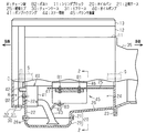
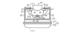
以下、内燃機関の実施形態を図1及び図2に従って説明する。なお、以下の説明では、図1における左側を内燃機関の前側、図1における右側を内燃機関の後側とする。
先ず、内燃機関の構成について説明する。図1に示すように、内燃機関は、内部に複数の気筒を有するシリンダブロック11を備えている。シリンダブロック11には、気筒内を往復動作するピストンによって回転させられるクランクシャフトSが挿通されている。クランクシャフトSは、シリンダブロック11全体を前後方向に貫通しており、クランクシャフトSの前端部及び後端部がそれぞれシリンダブロック11の外部に突出している。
Hereinafter, an embodiment of an internal combustion engine will be described with reference to FIGS. 1 and 2. In the following description, the left side in FIG. 1 is the front side of the internal combustion engine, and the right side in FIG. 1 is the rear side of the internal combustion engine.
First, the configuration of the internal combustion engine will be described. As shown in FIG. 1, the internal combustion engine includes a
シリンダブロック11の上部には、吸気ポート及び排気ポート等が区画形成されたシリンダヘッド12が固定されている。また、シリンダヘッド12の内部には、吸気ポートや排気ポートを開閉するバルブ機構が設けられている。シリンダヘッド12の上部には、当該シリンダヘッド12に設けられたバルブ機構等を覆うヘッドカバー13が固定されている。
A
シリンダブロック11の下部には、エンジンオイルを貯留するためのオイルパン20が固定されている。オイルパン20は、シリンダブロック11に固定される上部ケース21と、その上部ケース21の下部に固定される下部ケース29とで構成されている。なお、シリンダブロック11と上部ケース21(オイルパン20)との間には、液状ガスケットが介在していて、この液状ガスケットにより両者の間のシール性が確保されている。
An
図1及び図2に示すように、上部ケース21は、全体として有底四角箱状になっていて、前壁22、前壁22に対向する後壁23、前壁22及び後壁23をつなぐ一対の側壁24、これらの壁の下部に位置する底壁26を有する。上部ケース21の前壁22には、その前壁22の上端から下方側に向かって円弧状に切り欠かれた切欠部22aが設けられている。
As shown in FIGS. 1 and 2, the
図2に示すように、上部ケース21の側壁24には、他方の側壁24側へと向かって突出する板状の補強リブ25が設けられている。補強リブ25は、一対の側壁24のそれぞれに設けられている。図1に示すように、各補強リブ25は、上部ケース21の後壁23から、上部ケース21の前後方向およそ4分の3の位置にまで至っている。
As shown in FIG. 2, the
図1に示すように、上部ケース21における底壁26の前側には、四角形状に開口した開口部26aが設けられている。上部ケース21の下部には、底壁26における開口部26aを下側から覆うように、下部ケース29が取り付けられている。下部ケース29は、有底四角箱状になっていて、エンジンオイルがこの下部ケース29に貯留される。
As shown in FIG. 1, a rectangular opening 26 a is provided on the front side of the
図1に示すように、シリンダブロック11の前面側には、チェーンケース30の後側部分を構成するリアケース31が取り付けられている。リアケース31は、上下方向において、オイルパン20の上部ケース21からシリンダヘッド12にまで至っていて、その上側がヘッドカバー13に覆われている。リアケース31は、シリンダブロック11の前面、シリンダヘッド12の前面、及びオイルパン20の上部ケース21の前面(前壁22の外面)に対して、ボルト等で取り付けられている。また、リアケース31は、上部ケース21における前壁22の切欠部22aを覆っている。リアケース31には、上部ケース21における前壁22の切欠部22aと対向する位置に図示しない貫通孔が設けられている。この貫通孔を介して、リアケース31の前側からオイルパン20の内部へとエンジンオイルが流通可能となっている。なお、リアケース31と、シリンダブロック11、シリンダヘッド12及びオイルパン20(上部ケース21)との間には、液状ガスケットが介在していて、この液状ガスケットによりシール性が確保されている。
As shown in FIG. 1, a
リアケース31の前側には、全体としてリアケース31と略同一の平面視形状をなすフロントケース32が取り付けられている。フロントケース32は、リアケース31と同様に上側がヘッドカバー13に覆われている。これらリアケース31とフロントケース32との間には、チェーンCを収容するためのチェーン室Rが区画されている。なお、図1では、チェーンCの例として、クランクシャフトSの回転を、後述するオイルポンプ40に伝達するためのチェーンCを破線で図示している。
A
シリンダブロック11の後面及びオイルパン20の後面(後壁23の外面)には、ボルト等によりトランスミッションケース35が取り付けられている。トランスミッションケース35の内部には、クランクシャフトSの回転が伝達される図示しないトランスミッションが収容されている。
A
図1に示すように、オイルパン20(上部ケース21)の内部には、オイルパン20の下部ケース29内に貯留されたエンジンオイルを吸い上げて圧送するオイルポンプ40が配置されている。なお、オイルポンプ40は、ボルト等によってシリンダブロック11に固定されている。すなわち、この実施形態においてオイルポンプ40は、シリンダブロック11に固定されたエンジン部品に相当する。
As shown in FIG. 1, an
オイルポンプ40は、エンジンオイルを圧送するための歯車機構を収容するポンプハウジング41を備えている。ポンプハウジング41は、上部ケース21の前壁22に沿うように配置されている。ポンプハウジング41の前面からは、その内部に収容された歯車機構に駆動力を伝達するポンプ軸42が突出している。ポンプ軸42は、上部ケース21における前壁22を、切欠部22aを介して貫通している。また、ポンプ軸42は、チェーンケース30のリアケース31を貫通している。そして、ポンプ軸42の先端部(前端部)は、チェーンケース30のチェーン室R内に位置している。ポンプ軸42の先端部には、チェーンCが掛け回されていて、チェーンCを介してクランクシャフトSの回転がポンプ軸42に伝達される。
The
ポンプハウジング41の後面には、オイルパン20における下部ケース29内に貯留されたエンジンオイルを吸い上げるためのオイルストレーナ43が接続されている。オイルストレーナ43は、全体として円管状になっていて、ポンプハウジング41から下部ケース29の底面に向かって延びている。
An
図1及び図2示すように、オイルパン20(上部ケース21)の内部には、ピストンの往復動作等に従って発生する振動を減衰させるためのバランサ装置45が収容されている。バランサ装置45は、クランクシャフトの回転に伴って回転駆動されるバランスウェイト等が収容されるバランサハウジング46を備えている。図2に示すように、バランサハウジング46の各側面(図2において左右両側の面)には、向かい合う上部ケース21の側壁24側へ向って突出する取付部47が設けられている。
As shown in FIGS. 1 and 2, a
バランサ装置45は、各取付部47の上面が補強リブ25の下面に当接するように配置されている。そして、取付部47とその取付部47に当接する補強リブ25とを貫通するように、取付部47側から複数のボルトB1が挿通されている。この実施形態では、ボルトB1は、バランサ装置45における取付部47それぞれにおいて前後方向に2つ並設されている(合計で4つ)。すなわち、バランサ装置45は、ボルトB1によりオイルパン20(上部ケース24における補強リブ25)に固定されている。
The
図1に示すように、チェーンケース30のリアケース31には、チェーン室R側からボルトB2が挿通されている。ボルトB2は、オイルパン20における上部ケース21の切欠部22aを介してオイルパン20の内部側へと至っており、その先端部がオイルポンプ40のポンプハウジング41に螺合されている。すなわち、オイルポンプ40とチェーンケース30とがボルトB2により連結されている。
As shown in FIG. 1, a bolt B <b> 2 is inserted into the
図1及び図2に示すように、オイルポンプ40のオイルストレーナ43には、板状のステー部材44が固定されている。ステー部材44は、オイルストレーナ43の外面からバランサ装置45におけるバランサハウジング46の下面へと延びている。ステー部材44のオイルストレーナ43側の端部は、オイルストレーナ43の外面に溶接等で固定されており、ステー部材44がオイルストレーナ43と一体化している。ステー部材44のバランサハウジング46側の端部には、下方側からボルトB3が挿通されている。ボルトB3の先端部は、バランサハウジング46に螺合されている。したがって、オイルポンプ40とバランサ装置45とはボルトB3により連結されている。また、上述したとおり、バランサ装置45はオイルパン20に固定されているので、オイルポンプ40とオイルパン20とは、バランサ装置45を介して連結されている。
As shown in FIGS. 1 and 2, a plate-
次に、上記のように構成された内燃機関の作用及び効果を説明する。
内燃機関が運転していてクランクシャフトSが回転している場合には、トランスミッションケース35の内部に収容されているトランスミッションが動作し、その動作に応じた振動がトランスミッションケース35に発生する。そして、トランスミッションケース35が振動すると、そのトランスミッションケース35が取り付けられているオイルパン20の上部ケース21にもその振動が伝わる。
Next, the operation and effect of the internal combustion engine configured as described above will be described.
When the internal combustion engine is operating and the crankshaft S is rotating, the transmission housed in the
ここで、上記実施形態では、オイルパン20の上部ケース21は、補強リブ25及びバランサ装置45のバランサハウジング46を介して、オイルポンプ40のステー部材44に連結されている。そして、オイルポンプ40は、シリンダブロック11に固定されているとともに、ボルトB2を介してチェーンケース30のリアケース31に連結されている。すなわち、オイルパン20(上部ケース21)は、バランサ装置45及びオイルポンプ40を介して、シリンダブロック11及びチェーンケース30と共に一体化した構造となっている。したがって、上述したようにトランスミッションケース35の振動がオイルパン20の上部ケース21に作用しても、その振動をシリンダブロック11やチェーンケース30に伝達させて、オイルパン20、シリンダブロック11及びチェーンケース30の一体的な構造物として受け止めることができる。そのため、オイルパン20の振動の程度とシリンダブロック11やチェーンケース30の振動の程度との間に生じる差を小さくできる。その結果、オイルパン20の上部ケース21とシリンダブロック11との間の液状ガスケットや、オイルパン20の上部ケース21とチェーンケース30のリアケース31との間の液状ガスケットに過度な負担がかかることを抑制できる。
Here, in the above embodiment, the
また、上記実施形態では、オイルパン20の上部ケース21の内部において、前壁22から、ポンプハウジング41、オイルストレーナ43、ステー部材44、バランサ装置45、補強リブ25を介して後壁23へと至る連結構造を有している。この上部ケース21の前壁22から後壁23への一連の連結構造が、上部ケース21の内部において前後方向に延びる「梁」のような構造として機能する。したがって、上記のような連結構造を有さない場合と比較して、オイルパン20における上部ケース21の前後方向と直交する方向の曲げに対する曲げ剛性等を向上させることができる。
Further, in the above embodiment, in the
さらに、上記実施形態の内燃機関においては、オイルポンプ40やバランサ装置45に関して、各ボルトB1〜B3で固定するための設計変更を施せば、上記一連の連結構造を実現できる。したがって、上記一連の連結構造を適用するにあたって、オイルポンプ40やバランサ装置45の本来の機能に大きな影響を及ぼすような大幅な設計変更が必要となる可能性は低い。
Furthermore, in the internal combustion engine of the above-described embodiment, the above-described series of connection structures can be realized by changing the design for fixing the
上記実施形態は、次のように変更できる。
・クランクシャフトSの軸方向におけるオイルパン20(上部ケース21)の一方側にチェーンケース30が取り付けられており、他方側にトランスミッションケース35が取り付けられており、オイルパン20(上部ケース21)の上側にシリンダブロック11が取り付けられた構成であれば、内燃機関の構成は問わない。例えば、シリンダヘッド12やヘッドカバー13の構成については適宜変更できる。
The embodiment described above can be modified as follows.
A
・オイルパン20は、上部ケース21及び下部ケース29の2つのケースで構成されていなくてもよい。例えば、オイルパン20は、一体的な1つのケースで構成されていてもよいし、3つ以上のケースを組み合わせて構成してもよい。
The
・オイルパン20の形状は適宜変更できる。例えば、オイルパン20の上部ケース21において切欠部22aの形状を適宜変更してもよい。また、チェーンケース30内のエンジンオイルをオイルパン20内に戻すことができる構成(貫通孔等)が設けられているのであれば、上部ケース21の切欠部22aを省略することもできる。さらに、オイルパン20全体の形状も、上記実施形態で例示したものに限らず、内燃機関全体のレイアウト等を勘案して適宜変更できる。
The shape of the
・オイルポンプ40のポンプハウジング41をチェーンケース30に連結できるのであれば、チェーンケース30の構成は適宜変更できる。例えば、リアケース31を省略して、フロントケース32を直接シリンダブロック11、シリンダヘッド12、及びオイルパン20(上部ケース21)に取り付けてもよい。この場合、例えば、ボルトB2に代えて、オイルポンプ40のポンプハウジング41からフロントケース32まで延びるようにステー部材を設けて、両者を連結すればよい。
If the
・クランクシャフトSの回転をオイルポンプ40に伝達するための構成は、チェーンCに限らない。例えば、湿式のタイミングベルトであってもよい。
・バランサ装置45は、上部ケース21の補強リブ25に固定されていなくてもよい。例えば、バランサ装置45のバランサハウジング46を上部ケース21の側壁24や後壁23に直接取り付けてもよい。
The structure for transmitting the rotation of the crankshaft S to the
The
・バランサ装置45を、シリンダブロック11に固定されたエンジン部品として構成することもできる。例えば、バランサ装置45を、その取付部47の上面がシリンダブロック11の下面に当接するように配置し、ボルトを介してバランサ装置45をシリンダブロック11に固定してもよい。また、バランサ装置45の取付部47を、上部ケース21における補強リブ25とシリンダブロック11とで挟み込んでこれらをボルトで共締めしてもよい。なお、バランサ装置45がシリンダブロック11に固定されているのであれば、オイルポンプ40は必ずしもシリンダブロック11に固定されていなくてもよい。この場合でも、オイルポンプ40がチェーンケース30に連結されていれば、バランサ装置45(エンジン部品)は、オイルポンプ40を介してチェーンケース30に連結されているといえる。
The
・バランサ装置45を省略することもできる。この場合、オイルポンプ40におけるステー部材44を、バランサ装置45に代えて上部ケース21の補強リブ25等に固定すればよい。このように、オイルポンプ40におけるステー部材44がオイルパン20のどこかの箇所に固定されていれば、オイルパン20は、オイルポンプ40に連結されているといえる。
The
・オイルポンプ40において、ポンプハウジング41からバランサ装置45に向って延びるステー部材を採用してもよい。この場合、オイルストレーナ43から延びるステー部材44と併用してもよい。
In the
・オイルパン20の内部においてオイルポンプ40及びバランサ装置45の配置は、適宜変更できる。例えば、内燃機関の前後方向において、バランサ装置45を、オイルポンプ40の前側に配置してもよい。この場合、バランサ装置45をボルトB2でチェーンケース30に連結すればよい。
The arrangement of the
・オイルパン20の内部において、オイルポンプ40、バランサ装置45、及び上部ケース21の補強リブ25以外の構成が連結されていてもよい。例えば、オイルパン20の内部に、シリンダブロック11に固定されたその他のエンジン部品が配置されているのであれば、オイルポンプ40やバランサ装置45に代えて又は加えて、そのエンジン部材をオイルパン20に連結してもよい。また、その他のエンジン部材がチェーンケース30に連結されていれば、オイルポンプ40を省略したとしても、オイルパン20は、エンジン部材を介して、シリンダブロック11及びチェーンケース30と一体化したような構造となる。また、上部ケース21に補強リブ25以外のリブが設けられているのであれば、補強リブ25に代えて又は加えてそのリブにオイルポンプ40やバランサ装置45を連結してもよい。
In the
S…クランクシャフト、C…チェーン、R…チェーン室、B1…ボルト、B2…ボルト、B3…ボルト、11…シリンダブロック、12…シリンダヘッド、13…ヘッドカバー、20…オイルパン、21…上部ケース、22…前壁、22a…切欠部、23…後壁、24…側壁、25…補強リブ、26…底壁、26a…開口部、29…下部ケース、30…チェーンケース、31…リアケース、32…フロントケース、35…トランスミッションケース、40…オイルポンプ、41…ポンプハウジング、42…ポンプ軸、43…オイルストレーナ、44…ステー部材、45…バランサ装置、46…バランサハウジング、47…取付部。 S ... crankshaft, C ... chain, R ... chain chamber, B1 ... bolt, B2 ... bolt, B3 ... bolt, 11 ... cylinder block, 12 ... cylinder head, 13 ... head cover, 20 ... oil pan, 21 ... upper case, 22 ... Front wall, 22a ... Notch, 23 ... Rear wall, 24 ... Side wall, 25 ... Reinforcement rib, 26 ... Bottom wall, 26a ... Opening, 29 ... Lower case, 30 ... Chain case, 31 ... Rear case, 32 DESCRIPTION OF SYMBOLS ... Front case, 35 ... Transmission case, 40 ... Oil pump, 41 ... Pump housing, 42 ... Pump shaft, 43 ... Oil strainer, 44 ... Stay member, 45 ... Balancer device, 46 ... Balancer housing, 47 ... Mounting part.
Claims (1)
前記オイルパンの内部には、前記シリンダブロックに固定されたエンジン部品が配置されており、
前記オイルパンと前記エンジン部品とが連結されており、前記エンジン部品と前記チェーンケースとが連結されていることを特徴とする内燃機関。 A cylinder block having cylinders, an oil pan attached to the lower part of the cylinder block, and attached to the outer surface of the cylinder block and the outer surface of the oil pan on one axial side of the crankshaft disposed in the cylinder block An internal combustion engine including a chain case and a transmission case attached to an outer surface of the cylinder block and an outer surface of an oil pan on the other axial side of the crankshaft,
Inside the oil pan, engine parts fixed to the cylinder block are arranged,
The internal combustion engine, wherein the oil pan and the engine part are connected, and the engine part and the chain case are connected.
Priority Applications (1)
| Application Number | Priority Date | Filing Date | Title |
|---|---|---|---|
| JP2016082092A JP2017190761A (en) | 2016-04-15 | 2016-04-15 | Internal combustion engine |
Applications Claiming Priority (1)
| Application Number | Priority Date | Filing Date | Title |
|---|---|---|---|
| JP2016082092A JP2017190761A (en) | 2016-04-15 | 2016-04-15 | Internal combustion engine |
Publications (1)
| Publication Number | Publication Date |
|---|---|
| JP2017190761A true JP2017190761A (en) | 2017-10-19 |
Family
ID=60085841
Family Applications (1)
| Application Number | Title | Priority Date | Filing Date |
|---|---|---|---|
| JP2016082092A Pending JP2017190761A (en) | 2016-04-15 | 2016-04-15 | Internal combustion engine |
Country Status (1)
| Country | Link |
|---|---|
| JP (1) | JP2017190761A (en) |
Cited By (3)
| Publication number | Priority date | Publication date | Assignee | Title |
|---|---|---|---|---|
| JP2020153260A (en) * | 2019-03-19 | 2020-09-24 | ダイハツ工業株式会社 | Oil pan for internal combustion engine for automobiles |
| JP2021127743A (en) * | 2020-02-14 | 2021-09-02 | マツダ株式会社 | Engine with balancer |
| JP2024033273A (en) * | 2022-08-30 | 2024-03-13 | トヨタ自動車株式会社 | chain case |
-
2016
- 2016-04-15 JP JP2016082092A patent/JP2017190761A/en active Pending
Cited By (6)
| Publication number | Priority date | Publication date | Assignee | Title |
|---|---|---|---|---|
| JP2020153260A (en) * | 2019-03-19 | 2020-09-24 | ダイハツ工業株式会社 | Oil pan for internal combustion engine for automobiles |
| JP7219131B2 (en) | 2019-03-19 | 2023-02-07 | ダイハツ工業株式会社 | Automotive internal combustion engine oil pan |
| JP2021127743A (en) * | 2020-02-14 | 2021-09-02 | マツダ株式会社 | Engine with balancer |
| JP7327196B2 (en) | 2020-02-14 | 2023-08-16 | マツダ株式会社 | engine with balancer |
| JP2024033273A (en) * | 2022-08-30 | 2024-03-13 | トヨタ自動車株式会社 | chain case |
| JP7718358B2 (en) | 2022-08-30 | 2025-08-05 | トヨタ自動車株式会社 | Chain case |
Similar Documents
| Publication | Publication Date | Title |
|---|---|---|
| CN104919157B (en) | Variable compression ratio internal combustion engine | |
| JP4858368B2 (en) | Engine balancer equipment | |
| JP2020012452A (en) | Cover structure of internal combustion engine | |
| JP2017190761A (en) | Internal combustion engine | |
| CN110735683A (en) | Cover structure of internal combustion engine | |
| JP5604976B2 (en) | Oil pan structure of internal combustion engine | |
| RU2703071C1 (en) | Device of actuator for internal combustion engine with variable compression ratio (versions) | |
| JP2008082198A (en) | Drive apparatus mounted on a vehicle body including a variable compression ratio internal combustion engine | |
| US20210048087A1 (en) | Balancer device for internal combustion engines | |
| WO2019171098A1 (en) | Variable-compression-ratio internal combustion engine | |
| JP6102265B2 (en) | Balancer device for vehicle engine | |
| CN104508321A (en) | Internal combustion engine | |
| JP6291973B2 (en) | Fuel pump mounting structure | |
| WO2019116434A1 (en) | Engine device | |
| JP2019035366A (en) | Cylinder head and internal combustion engine with the same | |
| JP3133994B2 (en) | Engine oil storage device | |
| CN210829494U (en) | Internal combustion engine for vehicle | |
| JP4359265B2 (en) | General-purpose engine muffler cover structure | |
| JP7327196B2 (en) | engine with balancer | |
| JP4146698B2 (en) | Engine cover mounting structure | |
| JP2016020647A (en) | Auxiliary member fixing structure and internal combustion engine | |
| CN110735731B (en) | Internal combustion engine cover structure | |
| JP7331682B2 (en) | Cylinder block | |
| JP6569467B2 (en) | Engine balancer device and motorcycle | |
| JP2005351164A (en) | Mounting structure of fuel injection pump |