JP2017190810A - Brake caliper - Google Patents
Brake caliper Download PDFInfo
- Publication number
- JP2017190810A JP2017190810A JP2016079614A JP2016079614A JP2017190810A JP 2017190810 A JP2017190810 A JP 2017190810A JP 2016079614 A JP2016079614 A JP 2016079614A JP 2016079614 A JP2016079614 A JP 2016079614A JP 2017190810 A JP2017190810 A JP 2017190810A
- Authority
- JP
- Japan
- Prior art keywords
- cylinder
- brake
- piston
- caliper
- brake caliper
- Prior art date
- Legal status (The legal status is an assumption and is not a legal conclusion. Google has not performed a legal analysis and makes no representation as to the accuracy of the status listed.)
- Pending
Links
Images

Landscapes
- Braking Arrangements (AREA)
Abstract
Description
本発明は、車両のブレーキディスクに対してピストンを変位させて当該ブレーキディスクにブレーキパッドを押圧させ得るブレーキキャリパに関するものである。 The present invention relates to a brake caliper that can displace a piston with respect to a brake disc of a vehicle and press the brake pad against the brake disc.
ブレーキキャリパ(brake caliper)は、車両のディスクブレーキを構成する部品から成り、ブレーキパッドをブレーキディスクに押圧させ、その摩擦によって車両の制動を可能とするものである。従来のディスクブレーキは、例えば鋳造品から成るキャリパ本体の一部にシリンダを形成し、そのシリンダにブレーキパッドが形成されたピストンを摺動自在に取り付けて構成されている(特許文献1にて開示されている)。そして、運転者によってブレーキ操作が行われると、シリンダ内でピストンが変位してブレーキパッドをブレーキディスクに押圧させることにより、車両の制動が行われるようになっている。 A brake caliper is composed of parts constituting a disc brake of a vehicle, and presses a brake pad against the brake disc and enables braking of the vehicle by friction. A conventional disc brake is configured by forming a cylinder in a part of a caliper body made of, for example, a cast product, and slidably attaching a piston having a brake pad formed on the cylinder (disclosed in Patent Document 1). Have been). When a brake operation is performed by the driver, the piston is displaced in the cylinder and the brake pad is pressed against the brake disk, so that the vehicle is braked.
しかしながら、上記従来技術においては、ピストンを含む一体の鋳造品から成るキャリパ本体が必要とされることから、鋳造のための型が必要となり、製造コストが嵩んでしまうという問題があった。また、キャリパ本体は、車両の制動時、ブレーキパッドからの大きな反力を受けることから比較的大きな強度が必要とされ、それ故、例えば一体のプレス加工部品等による代替えが難しいとされていた。 However, in the above prior art, since a caliper main body made of an integral casting including a piston is required, there is a problem that a mold for casting is required and the manufacturing cost increases. Further, the caliper main body is required to have a relatively large strength because it receives a large reaction force from the brake pad when the vehicle is braked. Therefore, it has been difficult to replace the caliper body with, for example, an integrated press-worked part.
本発明は、このような事情に鑑みてなされたもので、製造コストを低減させつつ必要な強度を保持することができるブレーキキャリパを提供することにある。 This invention is made | formed in view of such a situation, and is providing the brake caliper which can hold | maintain required intensity | strength, reducing manufacturing cost.
請求項1記載の発明は、車両のブレーキディスクに対してピストンを変位させて当該ブレーキディスクにブレーキパッドを押圧させ得るブレーキキャリパにおいて、一端が開口した有底円筒状の部材から成り、前記ピストンを変位可能に収容可能なシリンダと、前記シリンダの開口側の外周壁面から側方に突出形成された突出部と、前記シリンダを挿通し得る挿通孔が形成され、当該挿通孔の内側開口縁部にて前記突出部を当接させた状態で前記シリンダが固定されたキャリパ本体とを具備したことを特徴とする。
The invention according to
請求項2記載の発明は、請求項1記載のブレーキキャリパにおいて、前記突出部は、前記シリンダの開口端に形成されたフランジから成ることを特徴とする。 According to a second aspect of the present invention, in the brake caliper according to the first aspect, the projecting portion includes a flange formed at an open end of the cylinder.
請求項3記載の発明は、請求項1記載のブレーキキャリパにおいて、前記突出部は、前記シリンダの長手方向における任意位置に形成可能とされ、その形成位置に応じて前記ブレーキディスクに対する前記シリンダ及びピストンの位置決めを行い得ることを特徴とする。 According to a third aspect of the present invention, in the brake caliper according to the first aspect, the projecting portion can be formed at an arbitrary position in the longitudinal direction of the cylinder, and the cylinder and the piston with respect to the brake disc according to the formation position. It is possible to perform positioning.
請求項4記載の発明は、請求項1〜3の何れか1つに記載のブレーキキャリパにおいて、前記ピストンは、前記シリンダ内に充填された作動オイルによって変位可能とされるとともに、前記シリンダは、内周壁面に溝形状が形成され、当該溝形状に前記作動オイルを液密に収容するためのシール部材が配設可能とされたことを特徴とする。 According to a fourth aspect of the present invention, in the brake caliper according to any one of the first to third aspects, the piston is displaceable by operating oil filled in the cylinder, and the cylinder is A groove shape is formed on the inner peripheral wall surface, and a seal member for liquid-tightly storing the working oil can be disposed in the groove shape.
請求項1の発明によれば、一端が開口した有底円筒状の部材から成り、ピストンを変位可能に収容可能とされるとともに、外周壁面から側方に突出形成された突出部を有するシリンダと、シリンダを挿通し得る挿通孔が形成され、当該挿通孔の内側開口縁部にて突出部を当接させた状態でシリンダが固定されたキャリパ本体とを具備したので、シリンダを含む一体鋳造部品が不要とされ、製造コストを低減させつつ必要な強度を保持することができる。 According to the first aspect of the present invention, the cylinder is formed of a bottomed cylindrical member having one open end, and can accommodate the piston in a displaceable manner, and has a protruding portion that is formed to protrude laterally from the outer peripheral wall surface. And a caliper body to which the cylinder is fixed in a state in which the insertion hole through which the cylinder can be inserted is formed and the protruding portion is in contact with the inner opening edge of the insertion hole. Is not required, and the required strength can be maintained while reducing the manufacturing cost.
請求項2の発明によれば、突出部は、シリンダの開口端に形成されたフランジから成るので、例えばシリンダを深絞り加工にて成形した際のフランジを流用して突出部とすることができ、製造コストをより低減させることができる。
According to the invention of
請求項3の発明によれば、突出部は、シリンダの長手方向における任意位置に形成可能とされ、その形成位置に応じてブレーキディスクに対するシリンダ及びピストンの位置決めを行い得るので、ブレーキキャリパが取り付けられる車両に応じてシリンダ及びピストンの取付位置を任意設定することができる。
According to the invention of
請求項4の発明によれば、ピストンは、シリンダ内に充填された作動オイルによって変位可能とされるとともに、シリンダは、内周壁面に溝形状が形成され、当該溝形状に作動オイルを液密に収容するためのシール部材が配設可能とされたので、溝形状の加工を精度よく且つ容易に行わせることができる。
According to the invention of
以下、本発明の実施形態について図面を参照しながら具体的に説明する。
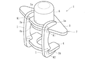
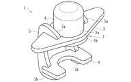
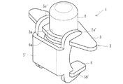
本実施形態に係るブレーキキャリパ1は、自動車等の車両におけるディスクブレーキを構成する部品から成り、ブレーキディスクに対してピストンを変位させて当該ブレーキディスクにブレーキパッドを押圧させ、その摩擦によって車両の制動を可能とするもので、図1〜8に示すように、キャリパ本体2を構成する第1部材3、第2部材4及び連結部材5と、シリンダ6とを有して構成されている。
Hereinafter, embodiments of the present invention will be specifically described with reference to the drawings.
The
第1部材3は、図8に示すように、ブレーキディスクDの一方の面側(本実施形態においては内側)に取り付けられる板状の金属製部材から成り、例えばプレス加工や切削加工等によって得られるものである。第2部材4は、同図に示すように、ブレーキディスクDの他方の面側(本実施形態においては外側)に取り付けられる板状の金属製部材から成り、第1部材3と同様、例えばプレス加工や切削加工等によって得られるものである。
As shown in FIG. 8, the
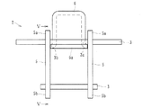
連結部材5は、第1部材3及び第2部材4に跨って形成され、これら第1部材3及び第2部材4を連結するための部材から成り、本実施形態においては、図3、4に示すように、シリンダ6を左右に挟んだ位置で第1部材3及び第2部材4に跨がって形成された一対の金属製の板状部材から成る。各連結部材5は、第1部材3及び第2部材4と同様、例えばプレス加工や切削加工等によって得られるものである。
The connecting
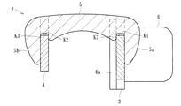
より具体的には、連結部材5は、図4、5に示すように、第1部材3の組み付け部位にて屈曲形成された第1アーム部5aと、第2部材4の組み付け部位にて屈曲形成された第2アーム部5bとを有した形状とされており、第1部材3及び第2部材4を連結部材5にて連結した状態において、第1アーム部5aが第1部材3の外側の面(図5中右側の面)に当接するとともに、第2アーム部5bが第2部材4の外側の面(図5中左側の面)に当接して組み付けられるようになっている。
More specifically, as shown in FIGS. 4 and 5, the connecting
また、本実施形態においては、図3〜5に示すように、第1部材3における連結部材5との連結部には、切欠きK1が形成されるとともに、第2部材4における連結部材5との連結部には、切欠きK2が形成されている。さらに、連結部材5における第1部材3及び第2部材4との連結部には、切欠きK3がそれぞれ形成されており、各連結部の切欠き(K1〜K3)同士が嵌合して組み付けられている。なお、第1部材3及び第2部材4と連結部材5との連結部は、切欠き(K1〜K3)が嵌合した状態において溶接やロウ付け等によって固定されている。
Moreover, in this embodiment, as shown to FIGS. 3-5, while notch K1 is formed in the connection part with the
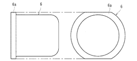
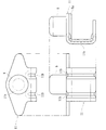
シリンダ6は、第1部材3に形成され、ピストンPを変位可能に収容するためのもので、一端が開口した有底円筒状の部材(カップ状部材)から成り、第1部材3及び第2部材4とは別体とされている。かかるシリンダ6は、例えば深絞り加工等によって成形された金属製の部材から成り、深絞り成形によって生じたフランジ6aが形成されている。このフランジ6aは、シリンダ6の開口側の外周壁面から側方に突出形成された突出部を構成するもので、図6に示すように、両側部が切削加工されて平面視で小判状に形成されている。これにより、連結部材5を組み付ける際、その第1アーム部5aがシリンダ6のフランジ6aに干渉してしまうのを防止することができる。
The
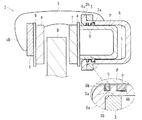
一方、キャリパ本体2を構成する第1部材3は、シリンダ6を挿通し得る挿通孔3aが形成され、当該挿通孔3aの内側開口縁部3b(図8に示すように、第1部材3における挿通孔3aの開口縁部であって、制動時にブレーキパッド7からの負荷がフランジ6aを介して付与される面)にてフランジ6a(突出部)を当接させた状態でシリンダ6が固定されている。また、本実施形態に係るシリンダ6は、挿通孔3aに挿通されつつフランジ6aが内側開口縁部3bに当接した状態において、ロウ付けや溶接等によって固定されている。なお、本実施形態においては、シリンダ6が第1部材3にのみ形成されているが、第1部材3及び第2部材4の両方にシリンダ6が形成されたもの、或いは第2部材4のみにシリンダ6が形成されたものとしてもよい。
On the other hand, the
ピストンPは、シリンダ6内に収容されて変位可能とされたもので、図8に示すように、シリンダ6の底面側において作動オイルを充填可能な収容空間Sを形成し、作動オイルを収容空間Sに注入すると、その注入された油圧にてピストンPが変位してブレーキディスクDをブレーキパッド7が押圧する方向に摺動するとともに、作動オイルを収容空間Sから排出すると、その排出された油圧にてピストンPが変位してブレーキディスクDからブレーキパッド7を離間させる方向に摺動し得るようになっている。
The piston P is accommodated in the
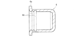
さらに、本実施形態に係るシリンダ6は、内周壁面に溝形状6bが形成され、当該溝形状6bに作動オイルを液密に収容するためのシール部材9(図8参照)が配設可能とされている。なお、シリンダ6には、作動オイルを収容空間Sに注入又は収容空間Sから排出させるための配管(不図示)が接続されており、運転者によるブレーキ操作に伴って作動オイルを注入又は排出させてピストンPを任意に変位させ得るようになっている。
Furthermore, the
ブレーキパッド7、8は、所定の摩擦材等から成るもので、制動操作時、ブレーキディスクDの一方の面(内面)と他方の面(外面)とに押圧されて摩擦を生じさせ、車両の制動を可能とするものである。なお、本実施形態においては、ブレーキパッド7は、取付部材aを介してピストンPに取り付けられるとともに、ブレーキパッド8は、取付部材bを介して第2部材4に取り付けられている。
The brake pads 7 and 8 are made of a predetermined friction material or the like, and are pressed against one surface (inner surface) and the other surface (outer surface) of the brake disc D during braking operation to cause friction, It enables braking. In the present embodiment, the brake pad 7 is attached to the piston P via the attachment member a, and the brake pad 8 is attached to the
そして、制動操作によってピストンPが図8中左方向に変位することによって、ブレーキパッド7がブレーキディスクDの一方の面に押圧するとともに、その反力でキャリパ本体2が同図中右方向に移動してブレーキパッド8がブレーキディスクDの他方の面に押圧することとなる。これにより、ブレーキパッド7、8が車輪と共に回転するブレーキディスクDの両面を押圧して摩擦を生じさせ、車両を制動し得るのである。
When the piston P is displaced leftward in FIG. 8 by the braking operation, the brake pad 7 is pressed against one surface of the brake disc D, and the
上記実施形態によれば、第1部材3及び第2部材4に跨って形成された連結部材5によって、ブレーキディスクDの一方の面側に位置する第1部材3及びブレーキディスクDの他方の面側に位置する第2部材4を連結して構成されるとともに、少なくとも第1部材3及び第2部材4の何れか一方にピストンPを変位可能なシリンダ6が形成されるので、シリンダ6を含む一体鋳造部品が不要とされ、製造コストを低減させつつ必要な強度を保持することができる。また、主に連結部材5の肉厚や材質等を任意選択することによってキャリパ本体2を任意強度とすることができるので、ブレーキキャリパ1が取り付けられる車両に応じて強度及び製造コストを任意設定することができる。
According to the above embodiment, the
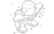
さらに、本実施形態に係る連結部材5は、シリンダ6を挟んだ位置で第1部材3及び第2部材4に跨がって形成された少なくとも一対の板状部材から成るので、必要な強度を確実に保持させることができる。しかるに、本実施形態に係る連結部材5に代えて、図9、10に示すように、第1アーム部5a’及び第2アーム部5b’を有した一体部品としての連結部材5’としてもよい。この場合、キャリパ本体2の強度をより向上させることができるとともに、部品点数を削減することができる。
Furthermore, since the connecting
またさらに、第1部材3における連結部材5との連結部、第2部材4における連結部材5との連結部、及び連結部材5における第1部材3及び第2部材4との連結部には、それぞれ切欠き(K1〜K3)が形成され、当該連結部の切欠き(K1〜K3)同士が嵌合して成るので、第1部材3、第2部材4及び連結部材5の位置決めをより正確且つ円滑に行わせることができるとともに、強度をより向上させることができる。
Furthermore, in the connection part with the
また、本実施形態に係るシリンダ6は、一端が開口した有底円筒状の部材から成り、第1部材3及び第2部材4とは別体とされたので、ピストンPを変位させるのに必要な強度及び材質のシリンダ6を独立して製造することができる。なお、シリンダ6は、キャリパ本体2を構成する他の部材(第1部材3、第2部材4及び連結部材5)と同一又は異なる材質或いは肉厚の部材としてもよい。
In addition, the
加えて、上記実施形態によれば、一端が開口した有底円筒状の部材から成り、ピストンPを変位可能に収容可能とされるとともに、外周壁面から側方に突出形成された突出部(上記実施形態においてはフランジ6a)を有するシリンダ6と、シリンダ6を挿通し得る挿通孔3aが形成され、当該挿通孔3aの内側開口縁部3bにて突出部(フランジ6a)を当接させた状態でシリンダ6が固定されたキャリパ本体2とを具備したので、シリンダ6を含む一体鋳造部品が不要とされ、製造コストを低減させつつ必要な強度を保持することができる。
In addition, according to the above-described embodiment, the projecting portion is formed of a bottomed cylindrical member having one end opened, and is capable of accommodating the piston P so as to be displaceable and projecting laterally from the outer peripheral wall surface (described above). In the embodiment, a
また、本実施形態に係る突出部は、シリンダ6の開口端に形成されたフランジ6aから成るので、例えばシリンダ6を深絞り加工にて成形した際のフランジ6aを流用して突出部とすることができ、製造コストをより低減させることができる。なお、本実施形態においては、フランジ6aの両側部が切削加工されて平面視で小判状に形成されているが、切削加工しないもの、或いは他の形状に切削加工するものとしてもよい。
Moreover, since the protrusion part which concerns on this embodiment consists of the
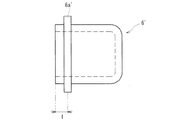
またさらに、シリンダ6のフランジ6aに代えて他の突出部としてもよく、例えば、図11に示すように、シリンダ6’の長手方向における任意位置(同図においては開口端から寸法tの位置)に突出部6a’を形成し、その形成位置に応じてブレーキディスクDに対するシリンダ6及びピストンPの位置決めを行い得るものとしてもよい。この場合、第1部材3の挿通孔3aにシリンダ6’を挿通させると、フランジ6aとは異なる位置の突出部6a’が第1部材3と当接して組み付けられるので、ブレーキキャリパ1が取り付けられる車両に応じてシリンダ6’及びピストンPの取付位置を任意設定することができる。
Furthermore, instead of the
また、本実施形態に係るピストンPは、シリンダ6内に充填された作動オイルによって変位可能とされるとともに、シリンダ6は、内周壁面に溝形状6bが形成され、当該溝形状6bに作動オイルを液密に収容するためのシール部材9が配設可能とされたので、溝形状6bの加工を精度よく且つ容易に行わせることができる。特に、本実施形態に係るシリンダ6は、キャリパ本体2を構成する他の部材とは別部材とされているので、キャリパ本体2に組み付ける前のシリンダ6に対して溝形状6bを容易に形成することができる。
Further, the piston P according to this embodiment can be displaced by the working oil filled in the
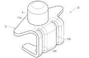
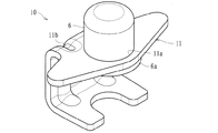
以上、本実施形態について説明したが、本発明はこれに限定されず、キャリパ本体2を構成する第1部材3、第2部材4及び連結部材5が一体構成のものであってもよい。例えば図12〜14に示すように、キャリパ本体11が一体構成のブレーキキャリパ10とし、そのキャリパ本体11に形成された挿通孔11aに対して別体のシリンダ6を挿通して組み付けるようにしてもよい。かかるキャリパ本体11は、板材をプレス成形したものから成り、折り曲げ部にビード11bが形成されて強度の向上が図られている。
Although the present embodiment has been described above, the present invention is not limited to this, and the
この場合であっても、上記実施形態と同様、一端が開口した有底円筒状の部材から成り、ピストンPを変位可能に収容可能とされるとともに、外周壁面から側方に突出形成された突出部(フランジ6a)を有するシリンダ6と、シリンダ6を挿通し得る挿通孔11aが形成され、当該挿通孔11aの内側開口縁部にて突出部(フランジ6a)を当接させた状態でシリンダ6が固定されたキャリパ本体11とを具備するので、シリンダ6を含む一体鋳造部品が不要とされ、製造コストを低減させつつ必要な強度を保持することができる。
Even in this case, as in the above-described embodiment, the projection is formed of a bottomed cylindrical member having one open end, and can accommodate the piston P so as to be displaceable, and is formed to project laterally from the outer peripheral wall surface. A
一端が開口した有底円筒状の部材から成り、ピストンを変位可能に収容可能なシリンダと、シリンダの開口側の外周壁面から側方に突出形成された突出部と、シリンダを挿通し得る挿通孔が形成され、当該挿通孔の内側開口縁部にて突出部を当接させた状態でシリンダが固定されたキャリパ本体とを具備したブレーキキャリパであれば、外観形状が異なるもの或いは他の機能が付加されたもの等にも適用することができる。 A cylinder having a bottomed cylindrical shape with an open end, a cylinder capable of displacing the piston, a projecting portion that projects laterally from the outer peripheral wall surface on the opening side of the cylinder, and an insertion hole through which the cylinder can be inserted If the brake caliper has a caliper main body to which the cylinder is fixed in a state where the protrusion is brought into contact with the inner opening edge of the insertion hole, the outer shape is different or other functions It can also be applied to those added.
1 ブレーキキャリパ
2 キャリパ本体
3 第1部材
3a 挿通孔
3b 内側開口縁部
4 第2部材
5 連結部材
5a 第1アーム部
5b 第2アーム部
6 シリンダ
6a フランジ
6b 溝形状
7 ブレーキパッド
8 ブレーキパッド
9 シール部材
10 ブレーキキャリパ
11 キャリパ本体
11a 挿通孔
11b ビード
P ピストン
D ブレーキディスク
S 収容空間
DESCRIPTION OF
Claims (4)
一端が開口した有底円筒状の部材から成り、前記ピストンを変位可能に収容可能なシリンダと、
前記シリンダの開口側の外周壁面から側方に突出形成された突出部と、
前記シリンダを挿通し得る挿通孔が形成され、当該挿通孔の内側開口縁部にて前記突出部を当接させた状態で前記シリンダが固定されたキャリパ本体と、
を具備したことを特徴とするブレーキキャリパ。 In the brake caliper that can displace the piston with respect to the brake disc of the vehicle and press the brake pad against the brake disc,
A cylinder having a bottomed cylindrical shape with one end opened, and capable of accommodating the piston in a displaceable manner;
A projecting portion formed to project laterally from the outer peripheral wall surface on the opening side of the cylinder;
A caliper body in which an insertion hole through which the cylinder can be inserted is formed, and the cylinder is fixed in a state in which the protrusion is in contact with an inner opening edge of the insertion hole;
A brake caliper characterized by comprising:
Priority Applications (1)
| Application Number | Priority Date | Filing Date | Title |
|---|---|---|---|
| JP2016079614A JP2017190810A (en) | 2016-04-12 | 2016-04-12 | Brake caliper |
Applications Claiming Priority (1)
| Application Number | Priority Date | Filing Date | Title |
|---|---|---|---|
| JP2016079614A JP2017190810A (en) | 2016-04-12 | 2016-04-12 | Brake caliper |
Publications (1)
| Publication Number | Publication Date |
|---|---|
| JP2017190810A true JP2017190810A (en) | 2017-10-19 |
Family
ID=60085737
Family Applications (1)
| Application Number | Title | Priority Date | Filing Date |
|---|---|---|---|
| JP2016079614A Pending JP2017190810A (en) | 2016-04-12 | 2016-04-12 | Brake caliper |
Country Status (1)
| Country | Link |
|---|---|
| JP (1) | JP2017190810A (en) |
Citations (3)
| Publication number | Priority date | Publication date | Assignee | Title |
|---|---|---|---|---|
| JPS57177432A (en) * | 1981-04-24 | 1982-11-01 | Akebono Brake Ind Co Ltd | Calliper of disc brake using a pin |
| US20080093180A1 (en) * | 2004-10-12 | 2008-04-24 | Armatec Survivability Corp. | Disc Brake System |
| US20100170755A1 (en) * | 2009-01-05 | 2010-07-08 | Robert Biggs | Modular brake caliper |
-
2016
- 2016-04-12 JP JP2016079614A patent/JP2017190810A/en active Pending
Patent Citations (3)
| Publication number | Priority date | Publication date | Assignee | Title |
|---|---|---|---|---|
| JPS57177432A (en) * | 1981-04-24 | 1982-11-01 | Akebono Brake Ind Co Ltd | Calliper of disc brake using a pin |
| US20080093180A1 (en) * | 2004-10-12 | 2008-04-24 | Armatec Survivability Corp. | Disc Brake System |
| US20100170755A1 (en) * | 2009-01-05 | 2010-07-08 | Robert Biggs | Modular brake caliper |
Similar Documents
| Publication | Publication Date | Title |
|---|---|---|
| JPWO2008047840A1 (en) | Disc caliper brake caliper | |
| JP2017190809A (en) | Brake caliper | |
| JP5919316B2 (en) | Vehicle disc brake | |
| JP4783822B2 (en) | Caliper body for disc brakes for vehicles | |
| US20200386284A1 (en) | Disc brake and piston boot | |
| CN110720000B (en) | Clamp body and disc brake | |
| JP6966273B2 (en) | Vehicle disc brakes | |
| JP2011017371A (en) | Disc brake for vehicle | |
| JP2010175040A (en) | Disc brake | |
| KR20180114406A (en) | Pad liner for braking apparatus | |
| JP6190199B2 (en) | Cylinder device | |
| KR102899539B1 (en) | Cover shim assembly | |
| JP2013113420A (en) | Disc brake | |
| JP2015105700A (en) | Disc brake | |
| JP2009127646A (en) | Pin slide disc brakes for vehicles | |
| JP2002161931A (en) | Disc brake | |
| JP2014126066A (en) | Disk brake for vehicle | |
| JP2009156446A (en) | Friction pads for vehicle disc brakes | |
| JP2015068426A (en) | Disc brake | |
| JP6267930B2 (en) | Resin piston for vehicle disc brake | |
| JP3959353B2 (en) | Resin piston for vehicle actuator | |
| JP2011102598A (en) | Piston for vehicle disk brake | |
| KR101114494B1 (en) | The Master Cylinder for Vehicles | |
| JP2023011413A (en) | Cylinder device | |
| JP3729633B2 (en) | Vehicle disc brake |
Legal Events
| Date | Code | Title | Description |
|---|---|---|---|
| A621 | Written request for application examination |
Free format text: JAPANESE INTERMEDIATE CODE: A621 Effective date: 20190228 |
|
| A977 | Report on retrieval |
Free format text: JAPANESE INTERMEDIATE CODE: A971007 Effective date: 20200227 |
|
| A131 | Notification of reasons for refusal |
Free format text: JAPANESE INTERMEDIATE CODE: A131 Effective date: 20200313 |
|
| A521 | Request for written amendment filed |
Free format text: JAPANESE INTERMEDIATE CODE: A523 Effective date: 20200512 |
|
| A02 | Decision of refusal |
Free format text: JAPANESE INTERMEDIATE CODE: A02 Effective date: 20200828 |