JP2017190836A - Drain trap - Google Patents
Drain trap Download PDFInfo
- Publication number
- JP2017190836A JP2017190836A JP2016081013A JP2016081013A JP2017190836A JP 2017190836 A JP2017190836 A JP 2017190836A JP 2016081013 A JP2016081013 A JP 2016081013A JP 2016081013 A JP2016081013 A JP 2016081013A JP 2017190836 A JP2017190836 A JP 2017190836A
- Authority
- JP
- Japan
- Prior art keywords
- drain
- discharge port
- cleaning unit
- sensor
- removal member
- Prior art date
- Legal status (The legal status is an assumption and is not a legal conclusion. Google has not performed a legal analysis and makes no representation as to the accuracy of the status listed.)
- Granted
Links
Images
Landscapes
- Details Of Valves (AREA)
Abstract
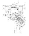
【課題】清掃部の作動状況を把握する。【解決手段】スチームトラップ1は、ドレンの排出口17dを有するケーシング10と、排出口17dの異物を除去する清掃部20と、清掃部20の作動を検出するセンサ40とを備えている。清掃部20は、ドレンが流通する位置に設けられ、温度変化によって変形するバイメタル22(変形部材)と、バイメタル22の変形によって排出口17dへ進退する除去部材23とを有している。センサ40は、除去部材23の移動に基づいて、清掃部20の作動を検出する。【選択図】図1An object of the present invention is to grasp the operation status of a cleaning unit. A steam trap (1) includes a casing (10) having a drain outlet (17d), a cleaning section (20) for removing foreign matter from the outlet (17d), and a sensor (40) for detecting the operation of the cleaning section (20). The cleaning unit 20 is provided at a position through which drain circulates, and has a bimetal 22 (deformable member) that deforms due to temperature changes, and a removing member 23 that advances and retreats toward the discharge port 17d as the bimetal 22 deforms. The sensor 40 detects the operation of the cleaning section 20 based on the movement of the removing member 23 . [Selection drawing] Fig. 1
Description
ここに開示された技術は、ドレントラップに関する。 The technology disclosed herein relates to a drain trap.
例えば特許文献1に開示されているように、ドレン(復水)の排出口に詰まった異物を除去する清掃部を備えたドレントラップが知られている。この清掃部は、温度変化によって変形する変形部材と、その変形部材の変形によって排出口へ進退する除去部材とを備えている。変形部材が配置されたスペースには、排出口から排出されたドレンが流入するように構成されている。ドレンが排出されている際には、変形部材は、ドレンによる加熱で変形し、除去部材を排出口から後退させている。一方、排出口に異物が詰まってドレンが排出されなくなると、変形部材の温度が低下する。これにより、変形部材は、ドレン排出時とは異なる態様で変形し、除去部材を排出口へ進入させる。この除去部材の進入によって、排出口に詰まっている異物が除去される。こうして、清掃部は、人的操作なく自動で排出口を清掃する。 For example, as disclosed in Patent Document 1, a drain trap including a cleaning unit that removes foreign matter clogged in a drain (condensate) discharge port is known. The cleaning unit includes a deformable member that deforms due to a temperature change, and a removal member that moves forward and backward to the discharge port due to the deformation of the deformable member. The drain discharged from the discharge port flows into the space where the deformable member is arranged. When the drain is discharged, the deformable member is deformed by heating with the drain, and the removing member is retracted from the discharge port. On the other hand, when the foreign substance is clogged in the discharge port and the drain is not discharged, the temperature of the deformable member decreases. Thereby, a deformation | transformation member deform | transforms in the aspect different from the time of drain discharge, and makes a removal member approach into a discharge port. By the entry of the removal member, the foreign matter clogged in the discharge port is removed. Thus, the cleaning unit automatically cleans the discharge port without human operation.
しかしながら、排出口を自動的に清掃する構成においては、人的操作で清掃する場合と比べて、清掃部の作動状況や清掃の頻度等を把握することが難しい。 However, in the configuration in which the discharge port is automatically cleaned, it is difficult to grasp the operating state of the cleaning unit, the frequency of cleaning, and the like as compared with the case of cleaning by a human operation.
ここに開示された技術は、かかる点に鑑みてなされたものであり、その目的とするところは、清掃部の作動状況を把握することにある。 The technology disclosed herein has been made in view of such a point, and the purpose thereof is to grasp the operating state of the cleaning unit.
ここに開示されたドレントラップは、ドレンの排出口を有するケーシングと、前記排出口の異物を除去する清掃部と、前記清掃部の作動を検出するセンサとを備え、前記清掃部は、ドレンが流通する位置に設けられ、温度変化によって変形する変形部材と、前記変形部材の変形によって前記排出口へ進退する除去部材とを有し、前記センサは、前記除去部材の移動に基づいて、前記清掃部の作動を検出するものとする。 The drain trap disclosed herein includes a casing having a drain discharge port, a cleaning unit that removes foreign matter from the discharge port, and a sensor that detects the operation of the cleaning unit. A deformation member provided at a circulating position and deformed by a temperature change; and a removal member that advances and retreats to the discharge port by deformation of the deformation member, and the sensor is configured to perform the cleaning based on movement of the removal member. The operation of the part shall be detected.
ここに開示されたドレントラップによれば、清掃部の作動状況を把握することができる。 According to the drain trap disclosed here, the operating condition of the cleaning unit can be grasped.
以下、例示的な実施形態を図面に基づいて詳細に説明する。図1は、スチームトラップ1の概略図である。 Hereinafter, exemplary embodiments will be described in detail with reference to the drawings. FIG. 1 is a schematic view of a steam trap 1.
スチームトラップ1は、フロート式スチームトラップを構成し、例えば蒸気システムに設けられる。スチームトラップ1は、蒸気の凝縮によって発生したドレン(復水)の中から蒸気を分離し、ドレンだけを自動的に排出する。スチームトラップ1は、ドレントラップの一例である。スチームトラップ1は、密閉容器であるケーシング10と、清掃部20と、清掃部20の作動を検出するセンサ40とを備えている。
The steam trap 1 constitutes a float type steam trap, and is provided, for example, in a steam system. The steam trap 1 separates the steam from the drain (condensate) generated by the condensation of the steam and automatically discharges only the drain. The steam trap 1 is an example of a drain trap. The steam trap 1 includes a
ケーシング10は、本体部11と、本体部11にボルト締結される蓋部12とを有している。ケーシング10の内部には、弁室13が形成されている。弁室13には、中空球形のフロート18が自由状態で収容されている。弁室13の下部には、蓋部12にねじ締結された弁座15及びフロート座19が設けられている。尚、フロート座19は、図1において手前側と奥側に2つ設けられている。
The
ケーシング10には、ドレンが流入する流入通路14と、ドレンが流出する流出通路17とが形成されている。スチームトラップ1では、流入通路14から弁室13に流入したドレンが、排出通路17を介して外部に流出する。
The
詳しくは、流入通路14は、本体部11に形成され、弁室13の上部に連通している。排出通路17は、本体部11と蓋部12と弁座15とに亘って形成されている。排出通路17は、弁座15に形成された上流部17aと、蓋部12に形成された中間部17bと、本体部11に形成された下流部17cとを含んでいる。上流部17aは、直線状の通路である。上流部17aの上流端には、弁室13に開口する排出口17dが形成されている。上流部17aの下流端は、中間部17bに連通している。中間部17bは、上流部17aから屈曲するように延びている。下流部17cは、ドレンを最終的にケーシング10から排出する部分である。
Specifically, the
フロート18は、弁室13内のドレンに浮かぶように構成され、ドレン量に応じて弁室13内を上下動する。フロート18は、弁座15に離着座することによって排出口17dを開閉する。詳しくは、フロート18は、ドレン量が所定量以下のときに、弁座15及びフロート座19に着座する。フロート18は、弁座15及びフロート座19の両方に着座しているときに、排出口17dを閉じる。一方、フロート18は、ドレン量が所定量以上になると浮上して、弁座15及びフロート座19から離れる。これにより、フロート18は、排出口17dを開く。フロート弁18は、弁体の一例である。
The
清掃部20は、排出通路17の排出口17dに付着した異物を自動的に除去する。清掃部20は、蓋部12に設けられている。つまり、清掃部20は、弁室13の外側に配置されている。清掃部20の一部は、蓋部12に設けられたキャップ部12aに覆われている。清掃部20は、ケース21と、バイメタル22と、除去部材23とを備えている。
The
ケース21は、略円筒状に形成されている。ケース21は、排出通路17の上流部17aと同軸上に配置され、蓋部12にねじ結合されている。ケース21の軸方向端部のうち弁座15と対向する端部には連通口21aが形成され、ドレンが連通口21aを介してケース21内部に流入する。ケース21には、バイメタル22が収容されている。つまり、バイメタル22は、ドレンが流通する位置に設けられており、ドレンに曝される。
The
バイメタル22は、温度変化に応じて湾曲(変形)する温度応動部材である。バイメタル22は、板状のものである。バイメタル22は、熱膨張係数の異なる2種類の金属または合金を接着した短冊状のバイメタル平板を螺旋状に巻いたものを更に螺旋状に巻いて二重つる巻き形に形成されている。バイメタル22は、低温になると半径が小さくなって長さが長くなり、高温になると半径が大きくなって長さが短くなる。つまり、バイメタル22は、温度変化によって軸方向に伸縮する。バイメタル22は、変形部材の一例である。
The
除去部材23は、断面が円形の棒状に形成されている。除去部材23は、ケース21と同軸上に配置され、ケース21の軸方向の両端部を貫通している。除去部材23は、ケース21に摺動自在に保持されている。除去部材23は、排出口17dに近い方の端部である先端部23aと、先端部23aとは反対側の端部である基端部23bとを有している。先端部23aは、排出口17dよりも小径に形成されている。除去部材23のうちケース21内の部分には、バイメタル22が巻回されている。バイメタル22の一端は、ケース21の軸方向端部のうち弁座15から遠い方の端部に固定されている。バイメタル22の他端は、除去部材23に設けられた受け部24に固定されている。受け部24は、除去部材23から半径方向に突出する環状板である。
The
センサ40は、除去部材23の基端部23bに対向する位置に配置され、蓋部12、詳しくは、キャップ部12aに取り付けられている。センサ40は、近接センサで構成され、除去部材23の接近及び離間を検出する。詳しくは、センサ40は、除去部材23の基端部23bが所定距離以下に近づいたことを検出する。この所定距離は、除去部材23の先端部23aが排出口17dから後退して、排出口17dが全開状態となっているときの基端部23bとセンサ40との距離に設定されている。センサ40は、検出結果を無線によって外部装置、例えば、制御部50に出力する。尚、センサ40は、有線によって外部装置と接続されていてもよい。
The
続いて、スチームトラップ1の動作について説明する。 Next, the operation of the steam trap 1 will be described.
蒸気システムの運転時には、スチームトラップ1に高温のドレンが流入する。流入したドレンは、弁室13を通って、排出口17d及び排出通路17を介してスチームトラップ1から流出する。このとき、流出通路17を流通するドレンの一部は、連通口21aを介してケース21内に流入する。バイメタル22は、ドレンに曝されて高温(例えば、90℃以上)になり、収縮する。バイメタル22の収縮変形により、除去部材23は、排出口17dから後退した状態にされる。こうして、排出口17dは、全開状態になる。
During operation of the steam system, hot drain flows into the steam trap 1. The drain that flows in flows out of the steam trap 1 through the
このとき、除去部材23の基端部23bは、センサ40に接近している。センサ40は、除去部材23の接近を検出する。
At this time, the
排出口17dに異物が詰まった場合には、排出口17dからドレンが全く又は殆ど排出されなくなる。その場合、バイメタル22は、高温のドレンに曝されなくなる。そうすると、バイメタル22の温度が低下し、バイメタル22が伸長する。このバイメタル22の伸長変形により、除去部材23は、排出口17dへ進入する。排出口17dに除去部材23が進入すると、先ず、詰まっている異物のうち除去部材23が貫通する領域(例えば、中央領域)の異物が押し出されて除去される。そして、異物が除去されてできた開口からドレンが排出される。この開口から排出されるドレンの流れは高速であるため、このドレンの高速流によって排出口17dに残存する異物が除去され得る。こうして、排出口17dに詰まった異物を除去することができる。
When foreign matter is clogged in the
このとき、除去部材23の基端部23bは、センサ40から離間している。センサ40は、除去部材23の離間を検出する。
At this time, the
尚、蒸気システムの停止時にはドレンの流通がないため、バイメタル22が低温となって、伸長した状態となり、除去部材23は、排出口17dに進入している。蒸気システムの運転開始時には、排出口17dと除去部材23(先端部23a)との隙間からドレンが排出される。バイメタル22は、しだいに高温となり、収縮変形する。これにより、除去部材23が後退し、排出口17dが全開状態となる。このようなシステムの停止及び再開時の除去部材23の接近及び離間も、センサ40は検出する。
In addition, since there is no distribution | circulation of a drain at the time of a steam system stop, the bimetal 22 becomes low temperature, it will be in the expanded state, and the
このように、センサ40を設けることによって清掃部20の作動状況を把握することができる。つまり、清掃部20が排出口17dの清掃を自動的に行うが故に、清掃部20の作動状況、即ち、清掃の頻度や、清掃を適切に行えているか等をユーザが把握することが難しい。それに対し、センサ40を設けることによって、清掃部20の作動をセンサ40が自動的に検出する。具体的には、センサ40は、除去部材23の移動を検出する。除去部材23は、清掃部20のうち清掃時に移動する部材であるので、除去部材23の移動に基づいて、清掃部20の作動を的確に検出することができる。
Thus, by providing the
さらには、このように清掃部20の作動状況を把握することによって、排出口17dの状態や清掃部20の状態等を判断することができる。例えば、制御部50は、清掃部20の作動状況に基づいて清掃部20の作動頻度を求めることができる。清掃部20の頻繁な作動は、排出口17dが異物で頻繁に詰まることを表している。排出口17dが異物で頻繁に詰まる場合には、清掃部20で排出口17dを清掃しても、排出口17dの異物を完全には除去できず、清掃後にも排出口17dに異物が残存している可能性がある。つまり、弁座15の交換の要否を判定することができる。
Furthermore, by grasping the operating state of the
また、制御部50は、清掃部20の作動状況に基づいて清掃部20が適切に作動しているか否かを求めることができる。例えば、除去部材23がセンサ40から離間してからセンサ40の方へ戻ってくるまでの時間が長い場合には、除去部材23が排出口17dの異物をうまく除去できず、異物に引っかかって排出口17dから抜けない場合や、バイメタル22の作動不良や除去部材23の摺動不良により除去部材23が適切に動作していない場合等が考えられる。つまり、弁座15の交換の要否や清掃部20の交換の要否を判定することができる。
Further, the
以上のように、スチームトラップ1は、ドレンの排出口17dを有するケーシング10と、排出口17dの異物を除去する清掃部20と、清掃部20の作動を検出するセンサ40とを備え、清掃部20は、ドレンが流通する位置に設けられ、温度変化によって変形するバイメタル22(変形部材)と、バイメタル22の変形によって排出口17dへ進退する除去部材23とを有し、センサ40は、除去部材23の移動に基づいて、清掃部20の作動を検出する。
As described above, the steam trap 1 includes the
この構成によれば、清掃部20の除去部材23が排出口17dに進入することによって排出口17dの異物を除去する。つまり、除去部材23は、清掃部20のうち清掃時に移動する部材であり、センサ40は、除去部材23の移動を検出し、除去部材23の移動に基づいて清掃部20の作動を検出する。その結果、清掃部20の作動状況を的確に把握することができる。
According to this configuration, the
また、ケーシング10には、フロート弁18(弁体)を収容する弁室13と、弁室13からドレンを排出する排出通路17が形成され、排出口17dは、排出通路17の上流端において弁室13に開口するように設けられ、清掃部20は、弁室13の外側に設けられ、除去部材23は、排出口17dへ進入する先端部23aと先端部23aとは反対側の端部である基端部23bとを有し、センサ40は、基端部23bの移動を検出する。
Further, the
この構成によれば、清掃部20は、弁室13の外側に設けられている。さらに、除去部材23の基端部23bは、排出口17dから離れた位置、即ち、弁室13から離れた位置に設けられている。弁室13は、ドレンが流通すると共にフロート弁8が収容されているので、センサ40等を配置することが難しい。つまり、清掃部20における移動する部材のうち弁室13から離れた部分である基端部23bをセンサ40で検出することによって、センサ40を弁室13から離れた位置に配置することができる。その結果、センサ40の設置を容易にすることができる。
According to this configuration, the
《その他の実施形態》
以上のように、本出願において開示する技術の例示として、前記実施形態を説明した。しかしながら、本開示における技術は、これに限定されず、適宜、変更、置き換え、付加、省略などを行った実施の形態にも適用可能である。また、前記実施形態で説明した各構成要素を組み合わせて、新たな実施の形態とすることも可能である。また、添付図面および詳細な説明に記載された構成要素の中には、課題解決のために必須な構成要素だけでなく、前記技術を例示するために、課題解決のためには必須でない構成要素も含まれ得る。そのため、それらの必須ではない構成要素が添付図面や詳細な説明に記載されていることをもって、直ちに、それらの必須ではない構成要素が必須であるとの認定をするべきではない。
<< Other Embodiments >>
As described above, the embodiment has been described as an example of the technique disclosed in the present application. However, the technology in the present disclosure is not limited to this, and can also be applied to an embodiment in which changes, replacements, additions, omissions, and the like are appropriately performed. Moreover, it is also possible to combine each component demonstrated by the said embodiment and it can also be set as a new embodiment. In addition, among the components described in the attached drawings and detailed description, not only the components essential for solving the problem, but also the components not essential for solving the problem in order to illustrate the technology. May also be included. Therefore, it should not be immediately recognized that these non-essential components are essential as those non-essential components are described in the accompanying drawings and detailed description.
前記実施形態について、以下のような構成としてもよい。 About the said embodiment, it is good also as following structures.
例えば、前記実施形態では、ドレントラップの例としてスチームトラップ1について説明しているが、ドレントラップは、スチームトラップ1に限られるものではない。例えば、ドレントラップは、ドレン中の空気を内部に閉じ込めるエアトラップであってもよい。 For example, although the steam trap 1 has been described as an example of the drain trap in the embodiment, the drain trap is not limited to the steam trap 1. For example, the drain trap may be an air trap that traps air in the drain.
また、スチームトラップ1の構成は、前記の構成に限られない。ドレンの排出口を有するケーシングと、排出口の異物を除去する清掃部とを備える限り、任意の構成を採用することができる。 Moreover, the structure of the steam trap 1 is not restricted to the said structure. Any configuration can be adopted as long as a casing having a drain outlet and a cleaning unit for removing foreign matter from the outlet are provided.
センサ40は、近接センサに限られるものではない。除去部材23の移動を検出することができる限り、任意のセンサを採用することができる。また、センサ40は、除去部材23の移動を間接的に検出する構成であってもよい。例えば、バイメタル22の変形は、除去部材23の移動と連動しているので、バイメタル22の変形を検出することによって、除去部材23の移動を検出してもよい。
The
以上説明したように、ここに開示された技術は、ドレントラップについて有用である。 As described above, the technique disclosed herein is useful for the drain trap.
1 スチームトラップ
10 ケーシング
13 弁室
17d 排出口
18 フロート弁(弁体)
20 清掃部
22 バイメタル(変形部材)
23 除去部材
40 センサ
1
20
23
Claims (2)
前記排出口の異物を除去する清掃部と、
前記清掃部の作動を検出するセンサとを備え、
前記清掃部は、ドレンが流通する位置に設けられ、温度変化によって変形する変形部材と、前記変形部材の変形によって前記排出口へ進退する除去部材とを有し、
前記センサは、前記除去部材の移動に基づいて、前記清掃部の作動を検出することを特徴とするドレントラップ。 A casing having a drain outlet;
A cleaning section for removing foreign matter from the outlet;
A sensor for detecting the operation of the cleaning unit,
The cleaning unit is provided at a position where the drain circulates, and has a deformation member that deforms due to a temperature change, and a removal member that moves forward and backward to the discharge port due to deformation of the deformation member,
The drain trap according to claim 1, wherein the sensor detects the operation of the cleaning unit based on the movement of the removing member.
前記ケーシングには、弁体を収容する弁室と、前記弁室からドレンを排出する排出通路が形成され、
前記排出口は、前記排出通路の上流端において前記弁室に開口するように設けられ、
前記清掃部は、前記弁室の外側に設けられ、
前記除去部材は、前記排出口へ進入する先端部と先端部とは反対側の端部である基端部とを有し、
前記センサは、前記基端部の移動を検出することを特徴とするドレントラップ。 The drain trap according to claim 1, wherein
The casing is formed with a valve chamber for accommodating a valve body, and a discharge passage for discharging drain from the valve chamber,
The discharge port is provided to open to the valve chamber at an upstream end of the discharge passage,
The cleaning unit is provided outside the valve chamber,
The removal member has a distal end portion that enters the discharge port and a proximal end portion that is an end portion opposite to the distal end portion,
The drain trap is characterized in that the sensor detects movement of the base end portion.
Priority Applications (1)
| Application Number | Priority Date | Filing Date | Title |
|---|---|---|---|
| JP2016081013A JP6713815B2 (en) | 2016-04-14 | 2016-04-14 | Drain trap |
Applications Claiming Priority (1)
| Application Number | Priority Date | Filing Date | Title |
|---|---|---|---|
| JP2016081013A JP6713815B2 (en) | 2016-04-14 | 2016-04-14 | Drain trap |
Publications (2)
| Publication Number | Publication Date |
|---|---|
| JP2017190836A true JP2017190836A (en) | 2017-10-19 |
| JP6713815B2 JP6713815B2 (en) | 2020-06-24 |
Family
ID=60086202
Family Applications (1)
| Application Number | Title | Priority Date | Filing Date |
|---|---|---|---|
| JP2016081013A Active JP6713815B2 (en) | 2016-04-14 | 2016-04-14 | Drain trap |
Country Status (1)
| Country | Link |
|---|---|
| JP (1) | JP6713815B2 (en) |
Cited By (4)
| Publication number | Priority date | Publication date | Assignee | Title |
|---|---|---|---|---|
| WO2019064974A1 (en) | 2017-09-29 | 2019-04-04 | 富士フイルム株式会社 | Lithographic printing plate precursor and lithographic printing plate fabrication method |
| CN110136458A (en) * | 2019-05-21 | 2019-08-16 | 俞芳芳 | A kind of traffic lights with dedusting function |
| WO2021019926A1 (en) * | 2019-07-31 | 2021-02-04 | 株式会社テイエルブイ | Cleaning device and valve device equipped with same |
| JP2021025542A (en) * | 2019-07-31 | 2021-02-22 | 株式会社テイエルブイ | Cleaning device and valve device including the same |
Citations (5)
| Publication number | Priority date | Publication date | Assignee | Title |
|---|---|---|---|---|
| JPH05106751A (en) * | 1991-10-11 | 1993-04-27 | Kubota Corp | Air valve with cleaning device |
| JP2002181221A (en) * | 2000-12-11 | 2002-06-26 | Smc Corp | Flow control valve |
| JP2007138984A (en) * | 2005-11-15 | 2007-06-07 | Tlv Co Ltd | Float type steam trap |
| JP2008151222A (en) * | 2006-12-15 | 2008-07-03 | Tlv Co Ltd | steam trap |
| JP2011190821A (en) * | 2010-03-11 | 2011-09-29 | Tokyo Keiki Inc | Position detection structure of control valve |
-
2016
- 2016-04-14 JP JP2016081013A patent/JP6713815B2/en active Active
Patent Citations (5)
| Publication number | Priority date | Publication date | Assignee | Title |
|---|---|---|---|---|
| JPH05106751A (en) * | 1991-10-11 | 1993-04-27 | Kubota Corp | Air valve with cleaning device |
| JP2002181221A (en) * | 2000-12-11 | 2002-06-26 | Smc Corp | Flow control valve |
| JP2007138984A (en) * | 2005-11-15 | 2007-06-07 | Tlv Co Ltd | Float type steam trap |
| JP2008151222A (en) * | 2006-12-15 | 2008-07-03 | Tlv Co Ltd | steam trap |
| JP2011190821A (en) * | 2010-03-11 | 2011-09-29 | Tokyo Keiki Inc | Position detection structure of control valve |
Cited By (6)
| Publication number | Priority date | Publication date | Assignee | Title |
|---|---|---|---|---|
| WO2019064974A1 (en) | 2017-09-29 | 2019-04-04 | 富士フイルム株式会社 | Lithographic printing plate precursor and lithographic printing plate fabrication method |
| CN110136458A (en) * | 2019-05-21 | 2019-08-16 | 俞芳芳 | A kind of traffic lights with dedusting function |
| WO2021019926A1 (en) * | 2019-07-31 | 2021-02-04 | 株式会社テイエルブイ | Cleaning device and valve device equipped with same |
| JP2021025542A (en) * | 2019-07-31 | 2021-02-22 | 株式会社テイエルブイ | Cleaning device and valve device including the same |
| JP6895025B1 (en) * | 2019-07-31 | 2021-06-30 | 株式会社テイエルブイ | Cleaning device and valve device equipped with it |
| JP7294650B2 (en) | 2019-07-31 | 2023-06-20 | 株式会社テイエルブイ | CLEANING DEVICE AND VALVE DEVICE INCLUDING THE SAME |
Also Published As
| Publication number | Publication date |
|---|---|
| JP6713815B2 (en) | 2020-06-24 |
Similar Documents
| Publication | Publication Date | Title |
|---|---|---|
| JP6713815B2 (en) | Drain trap | |
| CN107152604B (en) | Steam trap, sterile double-beat drop valve, the operating method of steam trap and filling apparatus | |
| JP2018096488A (en) | Valve device | |
| JP6375142B2 (en) | steam trap | |
| JP6022733B2 (en) | steam trap | |
| WO2012168221A2 (en) | Steam trap and method for draining condensate | |
| JP4971121B2 (en) | steam trap | |
| JP2016056858A (en) | Steam trap | |
| JP2016033443A (en) | Liquid removal device, screw compressor, screw expander, and extended casing | |
| JP6322476B2 (en) | Float type steam trap | |
| JP7294650B2 (en) | CLEANING DEVICE AND VALVE DEVICE INCLUDING THE SAME | |
| KR20170126644A (en) | steam trap and managerial system thereof | |
| JP7115153B2 (en) | sanitary washing equipment | |
| JP6895025B1 (en) | Cleaning device and valve device equipped with it | |
| KR102581586B1 (en) | Operating method of hot water dispenser | |
| CN110792134A (en) | Siphon drainage system | |
| JP2007138984A (en) | Float type steam trap | |
| JP4890227B2 (en) | steam trap | |
| JP6086457B2 (en) | Strainer cleaning device | |
| JP4890092B2 (en) | Float type steam trap | |
| JP2018096509A (en) | Valve device | |
| JP7495711B2 (en) | Valve with cleaning mechanism | |
| JP2021095917A (en) | Valve having cleaning mechanism | |
| KR20170011008A (en) | Temperature sensitive pressure reducing valve and its working method | |
| JP2009121613A (en) | Valve member and valve device |
Legal Events
| Date | Code | Title | Description |
|---|---|---|---|
| A621 | Written request for application examination |
Free format text: JAPANESE INTERMEDIATE CODE: A621 Effective date: 20190228 |
|
| A131 | Notification of reasons for refusal |
Free format text: JAPANESE INTERMEDIATE CODE: A131 Effective date: 20191210 |
|
| A977 | Report on retrieval |
Free format text: JAPANESE INTERMEDIATE CODE: A971007 Effective date: 20191212 |
|
| A521 | Request for written amendment filed |
Free format text: JAPANESE INTERMEDIATE CODE: A523 Effective date: 20200207 |
|
| TRDD | Decision of grant or rejection written | ||
| A01 | Written decision to grant a patent or to grant a registration (utility model) |
Free format text: JAPANESE INTERMEDIATE CODE: A01 Effective date: 20200602 |
|
| A61 | First payment of annual fees (during grant procedure) |
Free format text: JAPANESE INTERMEDIATE CODE: A61 Effective date: 20200604 |
|
| R150 | Certificate of patent or registration of utility model |
Ref document number: 6713815 Country of ref document: JP Free format text: JAPANESE INTERMEDIATE CODE: R150 |
|
| R250 | Receipt of annual fees |
Free format text: JAPANESE INTERMEDIATE CODE: R250 |
|
| R250 | Receipt of annual fees |
Free format text: JAPANESE INTERMEDIATE CODE: R250 |
|
| R250 | Receipt of annual fees |
Free format text: JAPANESE INTERMEDIATE CODE: R250 |