JP2017190864A - Gear type continuously variable transmission - Google Patents
Gear type continuously variable transmission Download PDFInfo
- Publication number
- JP2017190864A JP2017190864A JP2016103743A JP2016103743A JP2017190864A JP 2017190864 A JP2017190864 A JP 2017190864A JP 2016103743 A JP2016103743 A JP 2016103743A JP 2016103743 A JP2016103743 A JP 2016103743A JP 2017190864 A JP2017190864 A JP 2017190864A
- Authority
- JP
- Japan
- Prior art keywords
- gear
- conical
- relay
- shaft
- gears
- Prior art date
- Legal status (The legal status is an assumption and is not a legal conclusion. Google has not performed a legal analysis and makes no representation as to the accuracy of the status listed.)
- Granted
Links
Images
Landscapes
- Structure Of Transmissions (AREA)
Abstract
Description
本発明は、移動手段、または輸送手段においての無段変速機に関する。The present invention relates to a continuously variable transmission in moving means or transportation means.
従来の移動手段、または輸送手段での無段変速機には金属ベルトと油圧による連続可変プーリーによりプーリー径を変化させることにより無段変速を可能としたものがある。Some continuously variable transmissions using conventional moving means or transport means enable continuously variable transmission by changing the pulley diameter with a continuously variable pulley using a metal belt and hydraulic pressure.
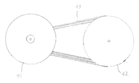
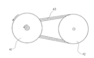
以下図3により従来の無段変速機について説明する。図においてプーリー41は金属ベルトを駆動させる入力側プーリーで金属ベルト43に伝わる動力を出力側プーリー42に伝え動力伝達させるもの。Hereinafter, a conventional continuously variable transmission will be described with reference to FIG. In the drawing, a
プーリーは油圧による連続可変式で図3、プーリ41とプーリー42を油圧によるプーリー径の変化により減速比を無段階で変速を行なうものである。The pulley is a continuously variable type by hydraulic pressure. In FIG. 3, the
1.以上に述べた従来の無段変速機では金属ベルトとプーリー間での滑りが発生しやすく動力伝達に問題がある。
2.ベルトとプーリー間の滑りを抑えるのに油圧で金属ベルトをプーリーで圧着する必要がある。
3.金属ベルトの強度、耐久性の問題により大非気量、重量車に対応できなかった。
4.プーリーの回転停止時において減速比の変更、変速することができない。1. The conventional continuously variable transmission described above is prone to slip between the metal belt and the pulley, and has a problem in power transmission.
2. In order to suppress slippage between the belt and the pulley, it is necessary to press the metal belt with a pulley by hydraulic pressure.
3. Due to problems with the strength and durability of the metal belt, it was not possible to cope with heavy and heavy vehicles.
4). When the pulley stops rotating, the gear ratio cannot be changed and the gear cannot be changed.
本発明は、このような従来の構成が有していた問題を解決しようとするものであり、無段変速機での金属ベルトの滑り、油圧でのプーリーで金属ベルトの圧着による動力伝達損失を低減し大非気量車、重量車に対応できる無段変速機を実現することを目的とするものである。The present invention is intended to solve the problems of such a conventional configuration, and the power transmission loss due to the slippage of the metal belt in the continuously variable transmission and the crimping of the metal belt with the hydraulic pulley is reduced. The object is to realize a continuously variable transmission that can be reduced and can be used for large non-volume vehicles and heavy vehicles.
本発明は、上記目的を達成するために入力軸に固定された大中小の大きさの異なる3枚の円錐形3連歯車と出力軸に固定された大中小大きさの異なる3枚の円錐形3連歯車を逆向きに配置した逆向き円錐形3連歯車とこれを連結する中継軸に固定された3枚からなる3連中継歯車を配置構成したものであり3連中継歯車は、中継軸とともに円錐形歯車の歯形にそって斜め上下方向に機関動力による油圧、または電動モーターなどの動力により移動する。In order to achieve the above object, the present invention provides three conical triple gears of different sizes of large, medium and small fixed to the input shaft and three conical shapes of large, medium and small sizes fixed to the output shaft. An inverted conical triple gear having three triple gears arranged in the reverse direction and a three-piece relay gear fixed to the relay shaft connecting the triple gears are arranged and configured. Along with the tooth shape of the conical gear, it moves in a slanting vertical direction by hydraulic pressure from engine power or power from an electric motor or the like.
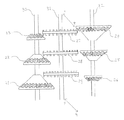
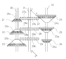
上記の課題解決手段による作用は次の通りである。入力軸30からの動力は低速回転伝達経路において円錐形歯車図1、23は中継歯車27を駆動させ逆向きに配置した逆向き円錐歯車24へ動力伝達され出力軸32を駆動させる。
減速比の変更には中継歯車軸31がGからF方向への移動により円錐形歯車23、中継歯車27、逆向き円錐形歯車24の噛み合いが円錐形歯車22、中継歯車28、逆向き円錐形歯車25、へ移行し出力軸32を駆動させることにより中速回転伝達経路となる。中継歯車軸F側では歯車の噛み合いが円錐形歯車21、中継歯車29、逆向き円錐形歯車26へと移行することにより高速回転伝達経路へと変速することができる。The operation of the above problem solving means is as follows. The power from the
To change the reduction ratio, the
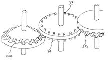
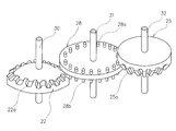
中継3連歯車には両側に円柱形歯形を備えることにより円錐形歯車と逆向き円錐形歯車との噛み合いに対し中継歯車下側図2、の円柱歯形34、は円錐形歯車22aと噛み合い中継歯車上側の歯形33は逆向き円錐形歯車25b、と噛み合うことによりスムーズに回転できるよう考慮してある歯車式無段変速機。The relay triple gear is provided with cylindrical teeth on both sides, so that the
上述したように本発明の歯車式無段変速機は歯車の噛み合う構造により滑りによる動力伝達損失を抑えるとともに滑りが一切発生しないので油圧による圧着動作をする必要がなく油圧による機関動力の損失を抑えることができ燃料消費を少なくでき動力伝達効率の高い歯車式無段変速機を提供できる。As described above, the gear type continuously variable transmission according to the present invention suppresses power transmission loss due to slippage due to the meshing structure of the gears, and does not generate any slippage, so that it is not necessary to perform crimping operation by hydraulic pressure and suppresses loss of engine power due to hydraulic pressure. Therefore, it is possible to provide a gear type continuously variable transmission that can reduce fuel consumption and has high power transmission efficiency.
また歯車の回転してない時においても円錐形3連歯車と逆向き
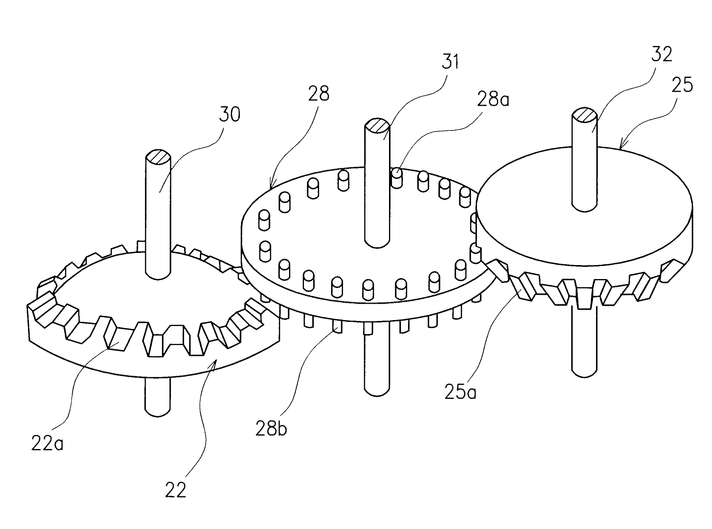
以下、本発明の実施の形態を図1、図2に基づいて説明する。Hereinafter, embodiments of the present invention will be described with reference to FIGS. 1 and 2.
図においては大中小の大きさの異なる3種類の3連円錐形歯車入力軸30、に固定されており円錐形歯車21、と同じ大きさの3枚の3連中継歯車は中継軸31、に固定されており中継歯車両側の円柱形歯形図2、33、34、を有し間隔は上下で異なる。大きさの異なる3種類の逆向きに配置した逆向き円錐形3連歯車は出力軸32、に固定されている。In the figure, three types of triple conical
以上、上記構成の動作を説明する。低速回転伝達経路において機関動力は入力軸30、に伝わり円錐形歯車23、と中継歯車27、に伝わり円錐形歯車を逆向きに配置した逆向き円錐形歯車24、に動力伝達され出力軸32、を駆動させる。無段変速においては3つの3連中継歯車に連結された中継軸31、が油圧、または電
また円錐形歯車、中継歯車、逆向きに配置した逆向き円錐形歯車は入力軸30、出力軸32、中継軸31、に対し3連以上の歯車でもよく円錐形歯車においては入力軸30、出力軸32、に対しどちらか一方が逆向きに配置した逆向き円錐形歯車であればよく歯車の伝達経路は低速回転伝達経路、23、27、24、中速回転伝達経路、22、28、25、高速回転伝達経路、21、29、26、の順番での配置でなくてもよい。The conical gear, the relay gear, and the reverse conical gear arranged in the reverse direction may be three or more gears for the
1:歯車式無段変速機本体
2:円錐形歯車
3:逆向き円錐形歯車
4:中継歯車
5:入力軸
6:出力軸
7:中継軸1: Gear type continuously variable transmission body 2: Conical gear 3: Reverse conical gear 4: Relay gear 5: Input shaft 6: Output shaft 7: Relay shaft
本願発明は、移動手段または輸送手段において用いられる歯車式の無段変速機の構成に関するものである。 The present invention relates to the configuration of a gear-type continuously variable transmission used in moving means or transporting means.
従来の移動手段または輸送手段で用いられている無段変速機には、たとえば図3に示すようなものがあった。 For example, a continuously variable transmission used in a conventional moving means or transportation means is as shown in FIG.
以下、この図3を参照して、従来の無段変速機の構成について説明する。図3において、符号41は入力側プーリー、同42は出力側プーリー、同43は、それら入力側プーリー41と出力側プーリー42との間に架け渡された金属ベルトを示しており、上記入力側プーリー41に入力された動力を上記金属ベルト43を介して上記出力側プーリー42に伝達するようになっている。
Hereinafter, the configuration of a conventional continuously variable transmission will be described with reference to FIG. In FIG. 3,
上記入力側プーリー41および出力側プーリー42は、それぞれ油圧により、そのプーリー径が連続的に変えられるようになっており、相互のプーリー径を連続的に変化させることにより無段階での変速を可能としている。
The
しかし、上記従来の無段変速機の構成の場合、次のような問題があった。
1.金属ベルト43とプーリー41,42間で滑りが発生しやすく、動力伝達に問題がある。
2.滑りを抑えるためには、油圧で金属ベルト43とプーリー41,42間の圧着を図る必要がある。
3.金属ベルト43の強度、耐久性の点から、大排気量、重量車に対応できない。
4.プーリー41,42が回転していない停止時において、減速比を変えることができない。
However, the configuration of the conventional continuously variable transmission has the following problems.
1. Sliding easily occurs between the
2. In order to suppress the slipping, it is necessary to press the
3. In view of the strength and durability of the
4). When the
本願発明は、このような従来の問題を解決するためになされたもので、順次大きさが大きくなる複数の円錐形歯車を備えた入力軸と、順次大きさが小さくなる複数の円錐形歯車を備えた出力軸と、入力軸に設けられた複数の円錐形歯車の歯形溝および出力軸に設けられた複数の円錐形歯車の歯形溝に沿って斜め方向に移動可能に設けられ、入力軸に設けられた複数の円錐形歯車および出力軸に設けられた複数の円錐形歯車に噛み合う複数の中継歯車を有する中継軸とを設け、中継軸を入力軸および出力軸の円錐型歯車に沿って斜め上下方向に移動させて入力軸に設けられた複数の円錐形歯車の歯形溝および出力軸に設けられた複数の円錐形歯車との噛み合い関係を変えることにより、滑りを発生させることなく、高強度で、入出力軸が回転していない時でも減速比を変えられるようにした歯車式無段変速機を提供することを目的とするものである。 The present invention has been made to solve such a conventional problem, and includes an input shaft having a plurality of conical gears that increase in size and a plurality of conical gears that decrease in size sequentially. An output shaft provided, a plurality of conical gear tooth grooves provided on the input shaft, and a plurality of conical gear tooth grooves provided on the output shaft. A plurality of conical gears provided and a relay shaft having a plurality of relay gears meshing with the plurality of conical gears provided on the output shaft, and the relay shaft is inclined along the conical gears of the input shaft and the output shaft. High strength without slipping by changing the meshing relationship between the tooth profile grooves of the conical gears provided on the input shaft and the conical gears provided on the output shaft. The input / output shaft rotates. It is an object of the present invention that even providing the gear-type continuously variable transmission to be changed gear ratio when no.
本願発明は、上記の目的を達成するために、次のような課題解決手段を備えて構成されている。
(1)請求項1の発明の課題解決手段
この発明の課題解決手段は、入力軸と、該入力軸の軸方向に沿って設けられた順次大きさが大きくなる複数の円錐形歯車と、出力軸と、該出力軸の軸方向に沿って設けられた上記入力軸の円錐形歯車とは逆向きで順次大きさが小さくなる複数の円錐形歯車と、上記入力軸と出力軸との間にあって、上記入力軸に設けられた複数の円錐形歯車の歯形溝および上記出力軸に設けられた複数の円錐形歯車の歯形溝に沿って斜め方向に移動可能に設けられた中継軸と、該中継軸の軸方向に沿って設けられ、上記入力軸に設けられた複数の円錐形歯車の歯形溝に噛み合う円柱形の歯形および上記出力軸に設けられた複数の円錐形歯車の歯形溝に噛み合う円柱形の歯形を有する複数の中継歯車とからなり、上記中継軸を上記入力軸に設けられた複数の円錐形歯車の歯形溝および上記出力軸に設けられた複数の円錐形歯車の歯形溝に沿って斜め方向に移動させることにより、上記入力軸に設けられた複数の円錐形歯車を上記中継軸に設けられた複数の中継歯車を介して上記出力軸に設けられた複数の円錐形歯車に選択的に噛み合わせて減速比を変えるように構成している。
In order to achieve the above object, the present invention comprises the following problem solving means.
(1) Problem Solving Means of the Invention of Claim 1 The problem solving means of the present invention includes an input shaft, a plurality of conical gears which are provided along the axial direction of the input shaft and increase sequentially, and an output. A plurality of conical gears which are opposite in direction to the shaft and the conical gear of the input shaft provided along the axial direction of the output shaft, and which are sequentially reduced in size, and between the input shaft and the output shaft. A relay shaft provided to be movable in an oblique direction along a tooth profile groove of the plurality of conical gears provided on the input shaft and a tooth profile groove of the plurality of cone gears provided on the output shaft, and the relay A cylindrical tooth shape that is provided along the axial direction of the shaft and meshes with the tooth-shaped grooves of the plurality of conical gears provided on the input shaft, and a cylinder that meshes with the tooth-shaped grooves of the plurality of conical gears provided on the output shaft. The relay shaft comprising a plurality of relay gears having a tooth shape Are moved in an oblique direction along the tooth-shaped grooves of the plurality of conical gears provided on the input shaft and the tooth-shaped grooves of the plurality of conical gears provided on the output shaft. A plurality of conical gears are selectively meshed with a plurality of conical gears provided on the output shaft via a plurality of relay gears provided on the relay shaft to change the reduction ratio.
このような構成では、たとえば上記入力軸の軸方向に沿って設けられた順次大きさが大きくなる複数の円錐形歯車が小、中、大と変化する第1〜第3の3段の構成、出力軸の軸方向に沿って設けられた逆向きで順次大きさが小さくなる複数の円錐形歯車が逆に大、中、小と変化する第1〜第3の3段の構成であると仮定し、上記中継軸に、それら小、中、大および大、中、小の各円錐形歯車相互の歯形部に選択的に噛み合う2組の円柱形の歯形を有する第1〜第3の複数の中継歯車が設けられているとすると、次のようにして、低速から、中速、中速から高速、またその逆へと任意の無段変速径路が形成される。 In such a configuration, for example, a first to third three-stage configuration in which a plurality of conical gears that are sequentially increased in size along the axial direction of the input shaft change from small to medium to large, It is assumed that a plurality of conical gears which are provided along the axial direction of the output shaft and which are gradually reduced in size in reverse directions have a first to third three-stage configuration that changes to large, medium and small. The relay shaft has a plurality of first to third plurality of cylindrical tooth shapes selectively meshing with the tooth shapes of the small, medium, large and large, medium and small conical gears. If a relay gear is provided, an arbitrary continuously variable transmission path is formed from low speed to medium speed, from medium speed to high speed, and vice versa as follows.
すなわち、まず上記中継軸の第1の中継歯車が上記入力軸の第1の円錐形歯車(小歯車)と出力軸の第1の円錐形歯車(大歯車)に噛み合っている時には、低速伝達経路が形成され、上記入力軸の回転が第1の円錐形歯車(小歯車)から上記中継軸の第1の中継歯車を介して上記出力軸の第1の円錐形歯車(大歯車)に伝達され、それらの歯車比から低速状態での駆動力の伝達が実現される。 That is, first, when the first relay gear of the relay shaft is meshed with the first conical gear (small gear) of the input shaft and the first conical gear (large gear) of the output shaft, the low speed transmission path. The rotation of the input shaft is transmitted from the first conical gear (small gear) to the first conical gear (large gear) of the output shaft via the first relay gear of the relay shaft. From these gear ratios, transmission of the driving force in the low speed state is realized.
次に、上記中継軸が上記低速状態から所定距離斜め方向に移動し、その第2の中継歯車が上記入力軸の第2の円錐形歯車(中歯車)と出力軸の第2の円錐形歯車(中歯車)に噛み合う状態になると、中速伝達経路が形成され、上記入力軸の回転が第2の円錐形歯車(中歯車)から中継軸の第2の中継歯車を介して出力軸の第2の円錐形歯車(中歯車)に伝達され、それらの歯車比から中速状態での駆動力の伝達が実現される。 Next, the relay shaft moves obliquely by a predetermined distance from the low speed state, and the second relay gear is a second conical gear (medium gear) of the input shaft and a second conical gear of the output shaft. When the state is meshed with the (medium gear), a medium speed transmission path is formed, and the rotation of the input shaft rotates from the second conical gear (medium gear) via the second relay gear of the relay shaft. Is transmitted to the two conical gears (medium gears), and the transmission of the driving force in the medium speed state is realized from the gear ratio thereof.
次に、上記中継軸が当該中速状態における位置から、さらに所定距離斜め方向に移動すると、その第3の中継歯車が上記入力軸の第3の円錐形歯車(大歯車)と上記出力軸の第3の円錐形歯車(小歯車)に噛み合う状態になって、高速伝達経路が形成され、上記入力軸の回転が第3の円錐形歯車(大歯車)から中継軸の第3の中継歯車を介して上記出力軸の第3の円錐形歯車(小歯車)に伝達され、それらの歯車比から高速状態での駆動力の伝達が実現される。 Next, when the relay shaft moves further in a diagonal direction by a predetermined distance from the position in the medium speed state, the third relay gear is connected to the third conical gear (large gear) of the input shaft and the output shaft. A high-speed transmission path is formed by meshing with the third conical gear (small gear), and the rotation of the input shaft is changed from the third conical gear (large gear) to the third relay gear of the relay shaft. To the third conical gear (small gear) of the output shaft, and transmission of the driving force in a high speed state is realized from the gear ratio.
また、これらとは逆方向に中継軸を移動させると、上記とは逆に、高速状態から中速状態、中速状態から低速状態に戻すことができる。 Further, when the relay shaft is moved in the opposite direction, it is possible to return from the high speed state to the medium speed state and from the medium speed state to the low speed state.
この場合において、上記入力軸の軸方向に沿って設けられた順次大きさが大きくなる第1〜第3の円錐形歯車および上記出力軸の軸方向に沿って設けられた逆向きで順次大きさが小さくなる第1〜第3の円錐形歯車の各々に対して、上記中継軸の第1〜第3の中継歯車が個別に対応して設けられている。 In this case, the first to third conical gears that increase in size sequentially along the axial direction of the input shaft and the sizes sequentially in the opposite directions provided along the axial direction of the output shaft. The first to third relay gears of the relay shaft are provided individually corresponding to each of the first to third conical gears with a small.
したがって、それぞれの歯車の噛み合い状態の変化は略連続したものとなり、それによって無段変速状態が実現される。 Therefore, the change of the meshing state of each gear becomes substantially continuous, thereby realizing a continuously variable transmission state.
以上の結果、本発明の構成によると、入力軸の軸方向に沿って設けられた順次大きさが大きくなる複数の円錐形歯車と、出力軸の軸方向に沿って設けられた入力軸の円錐形歯車とは逆向きで順次大きさが小さくなる複数の円錐形歯車と、入力軸と出力軸との間にあって、入力軸に設けられた複数の円錐形歯車の歯形溝および出力軸に設けられた複数の円錐形歯車の歯形溝に沿って斜め方向に移動可能に設けられた中継軸に設けられ、入力軸に設けられた複数の円錐形歯車の歯形溝に噛み合う円柱形の歯形および出力軸に設けられた複数の円錐形歯車の歯形溝に噛み合う円柱形の歯形を有する複数の中継歯車との相互に滑りのない確実な噛み合い構造によって、動力が伝達されるので、強度、耐久性が高く、大排気量、重量車にも対応することができる。 As a result of the above, according to the configuration of the present invention, the plurality of conical gears that are sequentially increased along the axial direction of the input shaft and the cone of the input shaft that is provided along the axial direction of the output shaft. A plurality of conical gears which are opposite to the shape gears and gradually decrease in size, and are provided between the input shaft and the output shaft, and provided in the tooth grooves and the output shaft of the plurality of conical gears provided on the input shaft. A cylindrical tooth profile and an output shaft which are provided on a relay shaft provided to be movable in an oblique direction along a tooth profile groove of a plurality of conical gears and mesh with tooth profile grooves of a plurality of cone gears provided on an input shaft Power is transmitted by a positive meshing structure that does not slip with each other and a plurality of relay gears that have a cylindrical tooth shape that meshes with the tooth profile grooves of a plurality of conical gears provided in, so the strength and durability are high. , Large displacement, heavy vehicles It can be.
また、滑りが発生しないので、従来のような動力の伝達損失を抑えることができ、油圧による圧着動作も不要となり、油圧作動による機関動力の損失もなくなる。 Further, since slip does not occur, the power transmission loss as in the conventional case can be suppressed, the pressure bonding operation by hydraulic pressure becomes unnecessary, and the loss of engine power by hydraulic operation is eliminated.
それらの結果、燃料消費量を少なくすることができ、動力伝達効率の高い無段変速機を提供することができる。 As a result, the fuel consumption can be reduced, and a continuously variable transmission with high power transmission efficiency can be provided.
また、本発明の構成では、上記入出力軸の相互に逆向きの円錐形歯車の歯形溝に噛み合う中継軸の中継歯車として、それら入出力軸の相互に逆向きの円錐形歯車の各歯形溝に噛み合い、同噛み合い状態において、それら各円錐形歯車の各歯形溝に沿って移動することができる円柱形の歯形を備えたものが採用されている。 Further, in the configuration of the present invention, as the relay gear of the relay shaft that meshes with the tooth groove of the conical gear of the input / output shaft opposite to each other, each tooth groove of the conical gear of the input / output shaft opposite to each other. And a cylindrical tooth profile that can move along each tooth groove of each of the conical gears is employed.
したがって、上記入出力軸(および円錐形歯車)、中継軸(および中継歯車)が回転していない時においても、入出力軸における相互に逆向きの円錐形歯車の歯形溝に沿って、中継軸の中継歯車の歯がスムーズに移動し、所望に変速操作することができる。 Therefore, even when the input / output shaft (and the conical gear) and the relay shaft (and the relay gear) are not rotating, the relay shaft is formed along the toothed grooves of the conical gears opposite to each other in the input / output shaft. The teeth of the relay gear can move smoothly, and a desired speed change operation can be performed.
以下、添付の図面を参照して、本発明の実施の形態に係る歯車式無段変速機の構成と作用について、詳細に説明する。 Hereinafter, with reference to the accompanying drawings, the configuration and operation of a gear type continuously variable transmission according to an embodiment of the present invention will be described in detail.
まず図1は、同歯車式無段変速機全体の構成を、また図2は、同歯車式無段変速機要部の構成を拡大して示している。 First, FIG. 1 shows an overall configuration of the same gear type continuously variable transmission, and FIG. 2 shows an enlarged configuration of a main part of the same gear type continuously variable transmission.
この実施の形態に係る歯車式無段変速機は、小中大と大きさの異なる第1〜第3の3枚の円錐形歯車21,22,23を備え、機関動力が入力される入力軸30と、大きさが同じ第1〜第3の3つの中継歯車27,28,29を備え、機関動力を中継する中継軸31と、大中小と大きさの異なる第1〜第3の3つの円錐型歯車24,25,26を備え、機関動力を出力する出力軸32とを備えて構成されている。入力軸30の第1〜第3の円錐形歯車21,22,23と出力軸32の第1〜第3の円錐形歯車24,25,26とは相互に逆向きとなるように配設されている。
The gear type continuously variable transmission according to this embodiment includes first to third conical gears 21, 22, and 23 having different sizes from small, medium, and large, and an input shaft to which engine power is input. 30, the first to third three relay gears 27, 28, 29 having the same size, the
中継軸31の第1〜第3の中継歯車27,28,29は、それぞれその大きさが上記第3の円錐形歯車23と同じであって、たとえば図2に第2の中継歯車28の構成で代表させて示すように、円板状の歯車本体の上下両側に複数の円柱形の歯形28a,28bを設けたものとなっている。
The first to third relay gears 27, 28, and 29 of the
この円柱形の歯形28a,28bの間隔は、たとえば噛み合う出力軸32側第2の円錐形歯車25の縦溝25a間の間隔、入力軸30側第2の円錐形歯車22の縦溝22a間の間隔に対応して上下のもので異なっている。
The intervals between the
そして、これら上下両側の複数の円柱形の歯形28a,28bのうち、上部側の円柱形の歯形28aが上記出力軸32側の第2の円錐形歯車25の縦溝25aに噛み合う一方、下部側の円柱形の歯形28bが上記入力軸30側の第2の円錐形歯車22の縦溝22aに噛み合うようになっている。
Of the plurality of
図2では、一例として、入力軸30の第2の円錐形歯車22、中継軸31の第2の中継歯車28、出力軸32の第2の円錐形歯車25の噛み合い関係のみを示しているが、これらの関係は、入力軸30の第1の円錐形歯車23、中継軸31の第1の中継歯車27、出力軸32の第1の円錐形歯車24との噛み合い関係、入力軸30の第3の円錐形歯車21、中継軸31の第3の中継歯車29、出力軸32の第3の円錐形歯車26との噛み合い関係においても全く同様であり、同様に構成されている。
In FIG. 2, as an example, only the meshing relationship of the second
入力軸30の第1の円錐形歯車23の縦溝23a、中継軸31の第1の中継歯車27上下の円柱形の歯形27a,27b、出力軸32の第1の円錐形歯車24の縦溝24a、入力軸30の第3の円錐形歯車21の縦溝21a、中継軸31の第3の中継歯車29上下の円柱形の歯形29a,29b、出力軸32の第3の円錐形歯車26の縦溝26aについては、図1の構成を参照。
The
上記のような円柱形の歯形27a,27b、28a,28b、29a,29bを有する第1〜第3の中継歯車27,28、29を固定している中継軸31は、油圧または電動モーターの動力により、たとえば図1中に矢印G−Fで示すように、上記入力軸30に固定された第1〜第3の円錐形歯車21,22,23および出力軸32に固定された第1〜第3の円錐形歯車24,25,26に沿って(それらの縦溝21a,22a,23a、24a,25a,26aに沿って)、斜め上下方向に所望に移動させることができるようになっている。
The
そして、同移動により、上記入力軸30の第1〜第3の円錐形歯車21,22,23と上記出力軸32の第1〜第3の円錐形歯車24,25,26同士を選択的に連係させ、それによって、低速から中速、中速から高速、高速から中速、中速から低速に無段階に変速するようになっている。
By the same movement, the first to third conical gears 21, 22, 23 of the
すなわち、まず上記中継軸31が図1に示す状態(F端位置)にあり、その第1の中継歯車27が入力軸30の第1の円錐形歯車(小歯車)23と出力軸32の第1の円錐形歯車(大歯車)24に噛み合っている時には、低速伝達経路が形成され、入力軸30の回転が第1の円錐形歯車(小歯車)23から中継軸31の第1の中継歯車27を介して出力軸32の第1の円錐形歯車(大歯車)24に伝達され、それらの歯車比から低速状態での駆動力の伝達が実現される。
That is, first, the
次に、上記中継軸31が図1に示す低速状態から所定距離G方向斜めに移動し、その第2の中継歯車28が入力軸30の第2の円錐形歯車(中歯車)22と出力軸32の第2の円錐形歯車(中歯車)25に噛み合う状態になると、中速伝達経路が形成され、入力軸30の回転が第2の円錐形歯車(中歯車)22から中継軸31の第2の中継歯車28を介して出力軸32の第2の円錐形歯車(中歯車)25に伝達され、それらの歯車比から中速状態での駆動力の伝達が実現される。
Next, the
次に、上記中継軸31が当該中速状態における位置から、さらに所定距離G方向斜めに移動し、G端位置に移動すると、その第3の中継歯車29が入力軸30の第3の円錐形歯車(大歯車)21と出力軸32の第3の円錐形歯車(小歯車)26に噛み合う状態になって、高速伝達経路が形成され、入力軸30の回転が第3の円錐形歯車(大歯車)21から中継軸31の第3の中継歯車29を介して出力軸32の第3の円錐形歯車(小歯車)26に伝達され、それらの歯車比から高速状態での駆動力の伝達が実現される。
Next, when the
また、これらとは逆に図1のGからF方向に3段階に中継軸31を移動させると、高速状態から中速状態、中速状態から低速状態に戻すことができる。
On the contrary, if the
この場合において、上記入力軸30の軸方向に沿って設けられた順次大きさが大きくなる第1〜第3の円錐形歯車21〜23および上記出力軸32の軸方向に沿って設けられた逆向きで順次大きさが小さくなる第1〜第3の円錐形歯車24〜26の各々に対して、上記中継軸31の第1〜第3の中継歯車27〜29が個別に対応して設けられている。
In this case, the first to third conical gears 21 to 23 that are sequentially increased in size along the axial direction of the
したがって、それぞれの歯車の噛み合い状態の変化は略連続したものとなり、それによって無段変速状態が実現される。 Therefore, the change of the meshing state of each gear becomes substantially continuous, thereby realizing a continuously variable transmission state.
また、以上の構成では、上記入出力軸30,32の相互に逆向きの円錐形歯車21〜23,24〜26の縦溝21a〜23a、24a〜26aに噛み合う中継軸31の中継歯車27〜29として、それら入出力軸30,32の相互に逆向きの円錐形歯車21〜23,24〜26の各縦溝21a〜23a、24a〜26aに噛み合い、同噛み合い状態において、それら各円錐形歯車21〜23,24〜26の各縦溝21a〜23a、24a〜26aに沿って斜めに移動することができる円柱形の歯形27a,27b、28a,28b、29a,29bを備えたものが採用されている。
In the above configuration, the relay gears 27 to 27 of the
したがって、以上の構成では、入出力軸30、32(円錐形歯車21〜23、24〜26)が回転していない時においても、入出力軸30,32における相互に逆向きの円錐形歯車21〜23、24〜26の各縦溝21a〜23a、24a〜26aに沿って、中継軸31の中継歯車27〜29の円柱形の歯形27a,27b、28a,28b、29a,29bが適切に噛み合い、同噛み合い状態において、それら縦溝21a〜23a、24a〜26aに沿ってスムーズに斜めに移動し得るので、回転停止時においても所望に変速することができる。
(変形例)
なお、以上の実施の形態では、入力軸30、中継軸31、出力軸32各々3連の歯車列構造を採用したが、これは各々3連以上の歯車列構造とすることもできる。
Therefore, in the above configuration, even when the input /
(Modification)
In the above embodiment, the
また、それら歯車列による動力伝達経路の配置は、必要に応じ上記のような低速から中速、中速から高速という速度順以外の配置とすることもできる。 Further, the arrangement of the power transmission paths by these gear trains may be arranged in a speed order other than the above from low speed to medium speed and from medium speed to high speed as necessary.
21〜23は、入力軸に固定された第1〜第3の円錐形歯車、21a〜23aは、入力軸に固定された第1〜第3の円錐形歯車21〜23の縦溝、24〜26は、出力軸に固定された第1〜第3の円錐形歯車、24a〜26aは、出力軸に固定された第1〜第3の円錐形歯車24〜26の縦溝、27〜28は、中継軸に固定された第1〜第3の中継歯車、30は、入力軸、31は、中継軸、32は、出力軸、33,34は、円柱形の歯形である。 21 to 23 are first to third conical gears fixed to the input shaft, 21a to 23a are vertical grooves of the first to third conical gears 21 to 23 fixed to the input shaft, 24 to 26 denotes first to third conical gears fixed to the output shaft, 24a to 26a denote longitudinal grooves of the first to third conical gears 24 to 26 fixed to the output shaft, and 27 to 28 denote The first to third relay gears fixed to the relay shaft, 30 is an input shaft, 31 is a relay shaft, 32 is an output shaft, and 33 and 34 are cylindrical teeth.
Claims (4)
Priority Applications (1)
| Application Number | Priority Date | Filing Date | Title |
|---|---|---|---|
| JP2016103743A JP6186553B1 (en) | 2016-04-11 | 2016-04-11 | Gear type continuously variable transmission |
Applications Claiming Priority (1)
| Application Number | Priority Date | Filing Date | Title |
|---|---|---|---|
| JP2016103743A JP6186553B1 (en) | 2016-04-11 | 2016-04-11 | Gear type continuously variable transmission |
Publications (2)
| Publication Number | Publication Date |
|---|---|
| JP6186553B1 JP6186553B1 (en) | 2017-08-23 |
| JP2017190864A true JP2017190864A (en) | 2017-10-19 |
Family
ID=59678226
Family Applications (1)
| Application Number | Title | Priority Date | Filing Date |
|---|---|---|---|
| JP2016103743A Expired - Fee Related JP6186553B1 (en) | 2016-04-11 | 2016-04-11 | Gear type continuously variable transmission |
Country Status (1)
| Country | Link |
|---|---|
| JP (1) | JP6186553B1 (en) |
Cited By (1)
| Publication number | Priority date | Publication date | Assignee | Title |
|---|---|---|---|---|
| WO2019064680A1 (en) | 2017-09-29 | 2019-04-04 | Kddi株式会社 | Node device, control method thereof, and program |
Citations (10)
| Publication number | Priority date | Publication date | Assignee | Title |
|---|---|---|---|---|
| FR638600A (en) * | 1927-07-30 | 1928-05-29 | Gradual speed change | |
| FR799686A (en) * | 1935-03-21 | 1936-06-17 | Gear shift system | |
| US2875628A (en) * | 1956-07-23 | 1959-03-03 | Walter Hermine Johanna | Variable gear |
| US2936641A (en) * | 1956-07-05 | 1960-05-17 | Alfred M Voelkl | Variable speed transmission |
| DE1119075B (en) * | 1958-09-10 | 1961-12-07 | Walter Burkart Dr Ing | Gear change transmission |
| US3377877A (en) * | 1966-10-13 | 1968-04-16 | Gen Electric | Adjustable-index gear train |
| JPS4970378U (en) * | 1972-10-02 | 1974-06-19 | ||
| JPH01303358A (en) * | 1988-05-31 | 1989-12-07 | Yukio Adachi | Conical double-axis continuously variable transmission |
| JP2005113969A (en) * | 2003-10-03 | 2005-04-28 | Nobuhisa Tomizawa | Transmission |
| JP2009092080A (en) * | 2007-08-17 | 2009-04-30 | Akihisa Matsuzono | Variable tooth-number geared continuously variable speed transmission |
-
2016
- 2016-04-11 JP JP2016103743A patent/JP6186553B1/en not_active Expired - Fee Related
Patent Citations (10)
| Publication number | Priority date | Publication date | Assignee | Title |
|---|---|---|---|---|
| FR638600A (en) * | 1927-07-30 | 1928-05-29 | Gradual speed change | |
| FR799686A (en) * | 1935-03-21 | 1936-06-17 | Gear shift system | |
| US2936641A (en) * | 1956-07-05 | 1960-05-17 | Alfred M Voelkl | Variable speed transmission |
| US2875628A (en) * | 1956-07-23 | 1959-03-03 | Walter Hermine Johanna | Variable gear |
| DE1119075B (en) * | 1958-09-10 | 1961-12-07 | Walter Burkart Dr Ing | Gear change transmission |
| US3377877A (en) * | 1966-10-13 | 1968-04-16 | Gen Electric | Adjustable-index gear train |
| JPS4970378U (en) * | 1972-10-02 | 1974-06-19 | ||
| JPH01303358A (en) * | 1988-05-31 | 1989-12-07 | Yukio Adachi | Conical double-axis continuously variable transmission |
| JP2005113969A (en) * | 2003-10-03 | 2005-04-28 | Nobuhisa Tomizawa | Transmission |
| JP2009092080A (en) * | 2007-08-17 | 2009-04-30 | Akihisa Matsuzono | Variable tooth-number geared continuously variable speed transmission |
Cited By (1)
| Publication number | Priority date | Publication date | Assignee | Title |
|---|---|---|---|---|
| WO2019064680A1 (en) | 2017-09-29 | 2019-04-04 | Kddi株式会社 | Node device, control method thereof, and program |
Also Published As
| Publication number | Publication date |
|---|---|
| JP6186553B1 (en) | 2017-08-23 |
Similar Documents
| Publication | Publication Date | Title |
|---|---|---|
| CN101617146B (en) | Continuously variable transmission | |
| CN106068402B (en) | Dual-clutch transmission capable of shifting under full load | |
| JP4698600B2 (en) | Continuously variable ratio transmission | |
| JP2007516385A (en) | Continuously variable ratio transmission device | |
| KR20170012771A (en) | Transmission for vehicles | |
| CN101260919A (en) | Multi speed transmission having a countershaft gearing arrangement | |
| KR20130131314A (en) | Gear scheme for infinitely variable transmission | |
| CN105090394B (en) | A kind of nine speed transmission | |
| CN110500388A (en) | Double shaft gearbox mechanism | |
| JP2012202473A (en) | Automatic transmission | |
| CN102146997B (en) | Dual-cavity semi-ring surface type power distribution continuously variable transmission | |
| CN107076272B (en) | Combined multi-stage transmission | |
| US10100903B2 (en) | Transmission for vehicle | |
| JP6186553B1 (en) | Gear type continuously variable transmission | |
| CN102146989B (en) | Sectional continuous stepless speed-change transmission system device | |
| CN201827305U (en) | Sectional continuous stepless speed-change transmission system device | |
| CN103827544B (en) | Manual gearbox for motor vehicle | |
| JP6266757B2 (en) | Always-mesh gearbox and vehicle powertrain | |
| US20170122411A1 (en) | Drive device for motor vehicle | |
| CN106321753B (en) | A kind of parallel axes planet shift transmission | |
| CN106715964A (en) | Multi-stage spur-planetary gearing | |
| CN212004118U (en) | High-ratio partition double countershaft gearbox | |
| KR101755816B1 (en) | Transmission for vehicles | |
| CN106321769A (en) | Double-cone stepless speed changing device | |
| JP6607075B2 (en) | Always meshing transmission |
Legal Events
| Date | Code | Title | Description |
|---|---|---|---|
| TRDD | Decision of grant or rejection written | ||
| A01 | Written decision to grant a patent or to grant a registration (utility model) |
Free format text: JAPANESE INTERMEDIATE CODE: A01 Effective date: 20170718 |
|
| R150 | Certificate of patent or registration of utility model |
Ref document number: 6186553 Country of ref document: JP Free format text: JAPANESE INTERMEDIATE CODE: R150 |
|
| R250 | Receipt of annual fees |
Free format text: JAPANESE INTERMEDIATE CODE: R250 |
|
| LAPS | Cancellation because of no payment of annual fees |