JP2017190901A - Drying furnace for painting - Google Patents
Drying furnace for painting Download PDFInfo
- Publication number
- JP2017190901A JP2017190901A JP2016080030A JP2016080030A JP2017190901A JP 2017190901 A JP2017190901 A JP 2017190901A JP 2016080030 A JP2016080030 A JP 2016080030A JP 2016080030 A JP2016080030 A JP 2016080030A JP 2017190901 A JP2017190901 A JP 2017190901A
- Authority
- JP
- Japan
- Prior art keywords
- temperature air
- casing
- low
- cylinder
- flame
- Prior art date
- Legal status (The legal status is an assumption and is not a legal conclusion. Google has not performed a legal analysis and makes no representation as to the accuracy of the status listed.)
- Granted
Links
Images
Classifications
-
- F—MECHANICAL ENGINEERING; LIGHTING; HEATING; WEAPONS; BLASTING
- F26—DRYING
- F26B—DRYING SOLID MATERIALS OR OBJECTS BY REMOVING LIQUID THEREFROM
- F26B21/00—Arrangements for supplying or controlling air or other gases for drying solid materials or objects
- F26B21/20—Circulating air or gases in closed cycles, e.g. wholly within the drying enclosure
- F26B21/25—Circulating air or gases in closed cycles, e.g. wholly within the drying enclosure partly outside the drying enclosure
-
- B—PERFORMING OPERATIONS; TRANSPORTING
- B05—SPRAYING OR ATOMISING IN GENERAL; APPLYING FLUENT MATERIALS TO SURFACES, IN GENERAL
- B05C—APPARATUS FOR APPLYING FLUENT MATERIALS TO SURFACES, IN GENERAL
- B05C9/00—Apparatus or plant for applying liquid or other fluent material to surfaces by means not covered by any preceding group, or in which the means of applying the liquid or other fluent material is not important
- B05C9/08—Apparatus or plant for applying liquid or other fluent material to surfaces by means not covered by any preceding group, or in which the means of applying the liquid or other fluent material is not important for applying liquid or other fluent material and performing an auxiliary operation
- B05C9/14—Apparatus or plant for applying liquid or other fluent material to surfaces by means not covered by any preceding group, or in which the means of applying the liquid or other fluent material is not important for applying liquid or other fluent material and performing an auxiliary operation the auxiliary operation involving heating or cooling
-
- F—MECHANICAL ENGINEERING; LIGHTING; HEATING; WEAPONS; BLASTING
- F26—DRYING
- F26B—DRYING SOLID MATERIALS OR OBJECTS BY REMOVING LIQUID THEREFROM
- F26B15/00—Machines or apparatus for drying objects with progressive movement; Machines or apparatus with progressive movement for drying batches of material in compact form
- F26B15/10—Machines or apparatus for drying objects with progressive movement; Machines or apparatus with progressive movement for drying batches of material in compact form with movement in a path composed of one or more straight lines, e.g. compound, the movement being in alternate horizontal and vertical directions
- F26B15/12—Machines or apparatus for drying objects with progressive movement; Machines or apparatus with progressive movement for drying batches of material in compact form with movement in a path composed of one or more straight lines, e.g. compound, the movement being in alternate horizontal and vertical directions the lines being all horizontal or slightly inclined
-
- F—MECHANICAL ENGINEERING; LIGHTING; HEATING; WEAPONS; BLASTING
- F26—DRYING
- F26B—DRYING SOLID MATERIALS OR OBJECTS BY REMOVING LIQUID THEREFROM
- F26B23/00—Heating arrangements
- F26B23/02—Heating arrangements using combustion heating
-
- F—MECHANICAL ENGINEERING; LIGHTING; HEATING; WEAPONS; BLASTING
- F26—DRYING
- F26B—DRYING SOLID MATERIALS OR OBJECTS BY REMOVING LIQUID THEREFROM
- F26B2210/00—Drying processes and machines for solid objects characterised by the specific requirements of the drying goods
- F26B2210/12—Vehicle bodies, e.g. after being painted
Landscapes
- Engineering & Computer Science (AREA)
- Mechanical Engineering (AREA)
- General Engineering & Computer Science (AREA)
- Chemical & Material Sciences (AREA)
- Combustion & Propulsion (AREA)
- Life Sciences & Earth Sciences (AREA)
- Sustainable Development (AREA)
- Drying Of Solid Materials (AREA)
Abstract
【課題】不良品の発生を抑制することが可能な塗装用乾燥炉の提供を目的とする。【解決手段】本発明の塗装用乾燥炉10は、塗装済みのワークWが供給される乾燥室11に、バーナ25により加熱された空気を循環供給するための循環路15が接続されている。循環路15には、バーナ25の炎を囲む保炎筒26と、保炎筒26を外側から囲み且つ保炎筒26より先端側へ延びるケーシング30と、が備えられている。ケーシング30は、外部からの低温空気Lをケーシング30内に導入するための低温空気導入口33を備えると共に、バーナ25により加熱された高温空気Hと低温空気Lとを循環路15へ排出するための排出口51Aを先端部に有している。そして、ケーシング30の内部には、排出口51Aから排出される前の高温空気Hと低温空気Lとを混合する混合機構50が形成されている。【選択図】図3An object of the present invention is to provide a coating drying furnace capable of suppressing the occurrence of defective products. In a drying furnace for painting 10 according to the present invention, a circulation path 15 for circulating and supplying air heated by a burner 25 is connected to a drying chamber 11 to which a coated workpiece W is supplied. The circulation path 15 includes a flame holding cylinder 26 that surrounds the flame of the burner 25, and a casing 30 that surrounds the flame holding cylinder 26 from the outside and extends from the flame holding cylinder 26 toward the tip side. The casing 30 includes a low-temperature air inlet 33 for introducing the low-temperature air L from the outside into the casing 30, and discharges the high-temperature air H and the low-temperature air L heated by the burner 25 to the circulation path 15. The discharge port 51A is provided at the tip. A mixing mechanism 50 that mixes the high-temperature air H and the low-temperature air L before being discharged from the discharge port 51 </ b> A is formed inside the casing 30. [Selection] Figure 3
Description
本発明は、塗装済みのワークを乾燥する塗装用乾燥炉に関する。 The present invention relates to a coating drying furnace for drying a painted workpiece.
従来、この種の塗装用乾燥炉として、ワークが供給される乾燥室に、バーナにより加熱された空気を循環供給するものが知られている(例えば、特許文献1参照)。また、近年、バーナの炎を囲む保炎筒と、保炎筒を外側から覆う燃焼筒と、を備えて、燃焼筒内に外部からの低温空気を供給する構成も提案されている。 2. Description of the Related Art Conventionally, as this type of coating drying furnace, one that circulates and supplies air heated by a burner to a drying chamber to which workpieces are supplied is known (for example, see Patent Document 1). In recent years, a configuration has been proposed in which a flame holding cylinder that surrounds the flame of a burner and a combustion cylinder that covers the flame holding cylinder from the outside are provided to supply low-temperature air from the outside into the combustion cylinder.
ところで、燃焼筒内に低温空気が導入される構成では、乾燥室へ供給される空気の温度のバラつきが大きいため、塗膜の黄変が生じ、不良品が発生するという問題があった。 By the way, in the configuration in which the low-temperature air is introduced into the combustion cylinder, there is a problem that the temperature of the air supplied to the drying chamber varies greatly, so that the coating film is yellowed and defective products are generated.
本発明は、上記事情に鑑みてなされたもので、不良品の発生を抑制することが可能な塗装用乾燥炉の提供を目的とする。 This invention is made | formed in view of the said situation, and aims at provision of the drying furnace for coating which can suppress generation | occurrence | production of inferior goods.
上記目的を達成するためになされた請求項1の発明は、塗装済みのワークが供給される乾燥室に、バーナにより加熱された空気を循環供給するための循環路が接続された塗装用乾燥炉であって、前記循環路には、前記バーナの炎を囲む保炎筒と、前記保炎筒を外側から囲み且つ前記保炎筒より先端側に突出するケーシングと、が備えられると共に、前記ケーシングは、外部からの低温空気を前記ケーシング内に導入するための低温空気導入口を備えると共に、前記バーナにより加熱された高温空気と前記低温空気とを前記循環路へ排出するための排出口を先端部に有し、前記ケーシングの内部には、前記排出口から排出される前の前記高温空気と前記低温空気とを混合する混合機構が形成されている塗装用乾燥炉である。
The invention of
請求項2の発明は、前記混合機構は、前記高温空気と前記低温空気が通過する通気路の断面積が縮小される圧縮部を有して、前記高温空気と前記低温空気の流れを絞るように構成されている請求項1に記載の塗装用乾燥炉である。
According to a second aspect of the present invention, the mixing mechanism has a compression section in which a cross-sectional area of an air passage through which the high temperature air and the low temperature air pass is reduced so as to restrict the flow of the high temperature air and the low temperature air. It is the drying furnace for coating of
請求項3の発明は、前記混合機構は、前記高温空気と前記低温空気を下方に誘導する下方誘導壁を有している請求項1又は2に記載の塗装用乾燥炉である。 A third aspect of the present invention is the coating drying furnace according to the first or second aspect, wherein the mixing mechanism has a lower guide wall for guiding the high temperature air and the low temperature air downward.
請求項4の発明は、前記ケーシング内には、前記ケーシングの内部空間を前記保炎筒の軸方向に二分して先端側空間と基端側空間とに区画する区画壁が設けられると共に、前記区画壁には、前記先端側空間と前記基端側空間とを連通させる連通孔が形成され、前記混合機構は、前記先端側空間に配置されると共に、前記保炎筒は、前記基端側空間に配置され、前記低温空気導入口は、前記基端側空間に連通している請求項1乃至3のうち何れか1の請求項に記載の塗装用乾燥炉である。
According to a fourth aspect of the present invention, in the casing, a partition wall that divides the internal space of the casing in the axial direction of the flame holding cylinder and divides the space into a front end side space and a base end side space is provided. The partition wall is formed with a communication hole for communicating the distal end side space and the proximal end side space, the mixing mechanism is disposed in the distal end side space, and the flame holding cylinder is disposed on the proximal end side 4. The coating drying furnace according to
請求項5の発明は、前記下方誘導壁は、前記連通孔の先方領域を上方から覆う上方カバー板と、前記上方カバー板から垂下して前記連通孔を先方から覆う先方カバー板と、を含んでなる請求項3に従属する請求項4に記載の塗装用乾燥炉である。 According to a fifth aspect of the present invention, the lower guide wall includes an upper cover plate that covers a front region of the communication hole from above, and a front cover plate that hangs down from the upper cover plate and covers the communication hole from the front. 5. A drying oven for coating according to claim 4, which is dependent on claim 3.
請求項6の発明は、前記ケーシングは、前記保炎筒を収容し且つ前記低温空気導入口を備えた筒形ケースの先端部に、前記筒形ケースとは別体の延長筒が取り付けられた構造をなし、前記混合機構は、前記延長筒の内部に配設されている請求項1乃至5のうち何れか1の請求項に記載の塗装用乾燥炉である。
According to a sixth aspect of the present invention, the casing is provided with an extension cylinder separate from the cylindrical case at the tip of the cylindrical case that houses the flame holding cylinder and includes the low-temperature air inlet. The coating drying furnace according to any one of
請求項7の発明は、前記保炎筒は、水平方向に沿って延び、前記ケーシングは、前記保炎筒の軸方向に沿って延びる水平筒部の先端部と、鉛直方向に沿って延びる鉛直筒部の上端部と、が連結された構造を有し、前記水平筒部は、前記保炎筒を内側に受容すると共に、前記低温空気導入口を備え、前記鉛直筒部は、前記水平筒部より下方に突出する部分に前記排出口を備えて、前記水平筒部から流れてくる前記高温空気と前記低温空気とを下方に移動させるように構成され、前記混合機構は、前記鉛直筒部によって構成されている請求項1に記載の塗装用乾燥炉である。
According to a seventh aspect of the present invention, the flame holding cylinder extends along a horizontal direction, and the casing includes a front end portion of a horizontal cylinder portion extending along an axial direction of the flame holding cylinder, and a vertical extending along the vertical direction. An upper end portion of the tube portion is connected, the horizontal tube portion receives the flame holding tube on the inside, and includes the low-temperature air inlet, and the vertical tube portion includes the horizontal tube. The discharge port is provided in a portion protruding downward from the portion, and the high temperature air and the low temperature air flowing from the horizontal tube portion are moved downward, and the mixing mechanism is configured to move the vertical tube portion It is the drying furnace for coating of
請求項8の発明は、前記鉛直筒部は、上下方向から見て、円形状又は前記水平筒部から遠い側へ膨出する半円状に形成されている請求項7に記載の塗装用乾燥炉である。 The invention according to claim 8 is the coating drying according to claim 7, wherein the vertical cylindrical portion is formed in a circular shape or a semicircular shape that bulges away from the horizontal cylindrical portion when viewed from the vertical direction. It is a furnace.
請求項9の発明は、前記鉛直筒部内には、前記保炎筒に先端側から対向する先端対向壁に沿って延在して、前記保炎筒を先端側から覆う遮熱板と、前記遮熱板よりも下方位置で前記先端対向壁から内側に張り出し、前記先端対向壁と前記遮熱板との間の隙間を下方から覆う仕切板と、が備えられている請求項7又は8に記載の塗装用乾燥炉である。 According to a ninth aspect of the present invention, in the vertical cylinder portion, a heat insulating plate that extends along a tip-facing wall facing the flame-holding tube from the tip side, and covers the flame-holding tube from the tip side; A partition plate that protrudes inward from the tip facing wall at a position lower than the heat shield plate and covers a gap between the tip facing wall and the heat shield plate from below is provided. It is a drying oven for painting described.
なお、保炎筒、筒形ケース、延長筒、水平筒部及び鉛直筒部は、円筒状に限られるものでなく、楕円筒状であってもよいし、多角形筒状であってもよい。 The flame holding cylinder, the cylindrical case, the extension cylinder, the horizontal cylinder part, and the vertical cylinder part are not limited to a cylindrical shape, and may be an elliptical cylindrical shape or a polygonal cylindrical shape. .
[請求項1〜3,6,7の発明]
本発明では、保炎筒を外側から囲むケーシングに備えられた低温空気導入口から低温空気がケーシング内に導入され、バーナにより加熱された高温空気と低温空気とが、ケーシングの先端部に備えられた排出口から循環路に排出される。そして、本発明では、ケーシングに、排出口から排出される前の高温空気と低温空気とを混合する混合機構が設けられている。本発明によれば、高温空気と低温空気とを混合し、その混合後の空気を乾燥室に供給することが可能となるので、乾燥室に供給される空気の温度のバラつきを抑えて、不良品の発生を抑制することが可能となる。
[Invention of Claims 1-3, 6, 7]
In the present invention, low temperature air is introduced into the casing from a low temperature air inlet provided in the casing surrounding the flame holding cylinder from the outside, and the high temperature air and the low temperature air heated by the burner are provided at the tip of the casing. It is discharged from the exhaust outlet to the circulation path. In the present invention, the casing is provided with a mixing mechanism for mixing high-temperature air and low-temperature air before being discharged from the discharge port. According to the present invention, high-temperature air and low-temperature air can be mixed, and the mixed air can be supplied to the drying chamber, so that variations in the temperature of the air supplied to the drying chamber can be suppressed and reduced. The generation of non-defective products can be suppressed.
混合機構としては、高温空気と低温空気の流れを絞ったり、下方へ誘導したり、迂回させたりする構成が挙げられる。1番目の例としては、請求項2の発明のように、高温空気と低温空気が通過する通気路の断面積が縮小される圧縮部を有する構成が挙げられる。また、2番目の例としては、請求項3の発明のように、高温空気と低温空気を下方に誘導する下方誘導壁を有する構成が挙げられる。また、保炎筒が水平方向に沿って延びる場合には、請求項7の発明のように、ケーシングが、保炎筒の軸方向に沿って延びる水平筒部の先端部と、鉛直方向に沿って延びる鉛直筒部の上端部と、が連結された構造を有し、水平筒部が、保炎筒を内側に受容すると共に、低温空気導入口を備え、鉛直筒部が、水平筒部より下方に突出する部分に排出口を備えて、水平筒部から流れてくる高温空気と低温空気とを下方に移動させるように構成され、混合機構が、鉛直筒部によって構成されている構成が挙げられる。請求項3,7の発明によれば、上方に溜まり易い高温空気を下方へ移動させることで、高温空気と低温空気が混合し易くなる。3番目の例としては、高温空気と低温空気が通過する通気路を、ジグザグ状やラビリンス状にする構成が挙げられる。
Examples of the mixing mechanism include a configuration in which the flow of high-temperature air and low-temperature air is reduced, guided downward, or detoured. As a first example, as in the invention of
なお、ケーシングを、保炎筒を収容し且つ前記低温空気導入口を備えた筒形ケースの先端部に、前記筒形ケースとは別体の延長筒が取り付けられた構造とし、その延長筒に混合機構が設けられた構成としてもよい(請求項6の発明)。この構成によれば、既存の塗装用乾燥炉に備えられた筒形ケースの先端に延長筒を取り付けることで、混合機構を備えたケーシングを形成することが可能となる。 The casing has a structure in which an extension cylinder separate from the cylindrical case is attached to the distal end portion of the cylindrical case that houses the flame holding cylinder and includes the low-temperature air introduction port. A mixing mechanism may be provided (invention of claim 6). According to this structure, it becomes possible to form the casing provided with the mixing mechanism by attaching the extension cylinder to the tip of the cylindrical case provided in the existing coating drying furnace.
[請求項4の発明]
本発明によれば、高温空気と低温空気が区画壁に形成された連通孔を通るときに、それら高温空気と低温空気を合流させ、その合流後の高温空気と低温空気を混合機構によって混合することが可能となる。
[Invention of claim 4]
According to the present invention, when the high temperature air and the low temperature air pass through the communication hole formed in the partition wall, the high temperature air and the low temperature air are merged, and the merged high temperature air and the low temperature air are mixed by the mixing mechanism. It becomes possible.
[請求項5の発明]
本発明によれば、下方誘導壁を簡易な構造で実現することが可能となる。
[Invention of claim 5]
According to the present invention, the lower guide wall can be realized with a simple structure.
[請求項8の発明]
本発明によれば、鉛直筒部が円形状又は水平筒部から遠い側へ膨出する半円状になっているので、水平筒部から鉛直筒部へ流れてきた高温空気と低温空気を鉛直筒部の周壁に沿って旋回させて、鉛直筒部内における高温空気と低温空気の滞留時間を長くすることが可能となり、高温空気と低温空気を混合させ易くすることが可能となる。
[Invention of Claim 8]
According to the present invention, since the vertical cylindrical portion is circular or semicircular that bulges away from the horizontal cylindrical portion, the high-temperature air and the low-temperature air flowing from the horizontal cylindrical portion to the vertical cylindrical portion are vertically By swirling along the peripheral wall of the cylindrical portion, the residence time of the high temperature air and the low temperature air in the vertical cylindrical portion can be lengthened, and the high temperature air and the low temperature air can be easily mixed.
[請求項9の発明]
本発明によれば、鉛直筒部の先端対向壁に高温空気が直接当たることが遮熱板によって抑制され、先端対向壁の劣化を抑えることが可能となる。また、鉛直筒部の上部へと流れて遮熱板と先端対向壁との間を下方へと通過する高温空気は、仕切板によって水平筒部側へと誘導されるので、水平筒部から流れてくる低温空気と混合され易くなる。
[Invention of claim 9]
According to the present invention, direct contact of high-temperature air with the tip-facing wall of the vertical cylinder portion is suppressed by the heat shield, and deterioration of the tip-facing wall can be suppressed. In addition, the high-temperature air that flows to the upper part of the vertical cylinder part and passes downward between the heat shield and the tip-facing wall is guided to the horizontal cylinder part side by the partition plate, and therefore flows from the horizontal cylinder part. It becomes easy to be mixed with the coming cold air.
[第1実施形態]
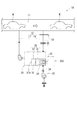
以下、本発明の第1実施形態を図1〜図3に基づいて説明する。図1に示すように、本実施形態の塗装用乾燥炉10は、塗装済みのワークW(例えば、自動車のボディ)が順次供給される乾燥室11と、乾燥室11に接続される循環路15と、を有している。循環路15は、例えば、ダクトで構成されている。循環路15の途中には、循環路15内の空気をバーナ25によって加熱する燃焼機構20が設けられている(図2参照)。そして、バーナ25により加熱された空気が乾燥室11に循環供給されるようになっている。なお、循環路15のうち乾燥室11から燃焼機構20へ空気を導入する部分が空気導入路16となっていて、循環路15のうち燃焼機構20から乾燥室11へ空気を戻す部分が空気帰還路17となっている。
[First Embodiment]
Hereinafter, a first embodiment of the present invention will be described with reference to FIGS. As shown in FIG. 1, a
以下、燃焼機構20の詳細について説明する。図1及び図3(A)に示すように、バーナ25を備えるバーナ装置25Sは、循環路15に隣接して備えられ、そのバーナ25が、循環路15を構成する壁部22に形成されたバーナ挿通孔22Aに挿通されて、循環路15内に突入している。これにより、循環路15内の空気がバーナ25によって加熱される。なお、バーナ装置25Sは、所謂、ガスバーナであって、バーナ25の他に、バーナ25に燃料ガスを供給するための燃料供給部(図示略)やバーナ25に空気を供給する空気供給部(図示略)が備えられている。また、塗装用乾燥炉10では、空気導入路16又は空気帰還路17に温度計18が備えられていて、バーナ装置25Sは、温度計18の計測結果に基づいて、バーナ25の出力を調整するようになっている。なお、図1には、空気導入路16に温度計18を備える例が示されている。
Hereinafter, the details of the
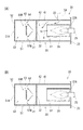
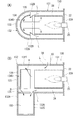
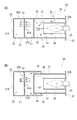
図3(A)に示すように、燃焼機構20には、バーナ25の炎を囲む保炎筒26と、保炎筒26を外側から囲むケーシング30と、が備えられている。保炎筒26は、両端が開放された構造をなしてバーナ挿通孔22Aの軸方向に延びている。詳細には、保炎筒26は、バーナ挿通孔22Aを有する壁部22に循環路15の内側から対向し、その壁部22との間に若干の隙間を有している。なお、以下では、保炎筒26の軸方向において、保炎筒26が循環路15内に突入する側を「先端側」又は「前側」と、反対側を「基端側」又は「後側」と、呼ぶことにする。
As shown in FIG. 3A, the
ケーシング30は、保炎筒26の軸方向に延びる筒状をなし、ケーシング30の後端(基端)は、循環路15を構成する壁部22にて閉塞されている。ケーシング30は、保炎筒26よりも軸長が長くなっていて、保炎筒26より先端側へ延びている。なお、図3(A)及び図3(B)に示す例では、ケーシング30と保炎筒26とが同軸上に配置されているが、ケーシング30の中心軸と保炎筒26の中心軸とがずれて配置されてもよい。
The
ケーシング30のうち保炎筒26を径方向外側から囲む部分(図3(A)の例では、保炎筒26の上側部分)には、ケーシング30内に低温空気Lを導入するための低温空気導入口33が形成されている。具体的には、図1に示されるように、塗装用乾燥炉10は、外部からの低温空気Lを取り込んでケーシング30内に供給するための低温空気供給装置35を備えていて、その低温空気供給装置35から延びる低温空気供給管34が低温空気導入口33に接続されている。そして、本実施形態では、ケーシング30の内部において、バーナ25により加熱された高温空気Hと、低温空気導入口33から導入された低温空気Lと、が合流するようになっている。
Low-temperature air for introducing the low-temperature air L into the
図3(A)に示すように、ケーシング30の先端部には、ケーシング30内の高温空気Hと低温空気Lを循環路15に排出するための排出口51Aが形成されている。本実施形態では、ケーシング30は、一端有底状に形成されて先端側に筒底壁52を有し、その筒底壁52に排出口51Aが形成されている。即ち、排出口51Aは、ケーシング30の先端面に形成されている。図3(A)に示す例では、排出口51Aは、保炎筒26と同軸上に配置されている。なお、本実施形態では、例えば、空気導入路16の途中で、低温空気Lの導入量と同じ量の空気が外部に排出されるようになっている。
As shown in FIG. 3A, a
さて、本実施形態では、ケーシング30の内部に、排出口51Aから排出される前の高温空気Hと低温空気Lを混合する混合機構50が設けられていて、これにより、乾燥室11に供給される空気の温度のバラつきを抑えることが可能となっている。以下、混合機構50について詳説する。
In the present embodiment, a
本実施形態の混合機構50は、高温空気Hと低温空気Lを下方に誘導する下方誘導壁53を有している。これにより、混合機構50では、上方に溜まり易い高温空気Hを下方へ移動させることが可能となり、高温空気Hと低温空気Lとが混合され易くなる。
The
具体的には、本実施形態では、ケーシング30内に、ケーシング30の内部空間を軸方向に二分して、基端側空間S1と先端側空間S2とに区画する区画壁31が設けられている。区画壁31には、基端側空間S1と先端側空間S2とを連通させる連通孔32が形成されている。保炎筒26は、基端側空間S1に配置され、低温空気導入口33は、基端側空間S1に連通している。そして、混合機構50は、先端側空間S2に配設されている。図3(A)に示す例では、連通孔32は、排出口51Aと同軸に配置されている。
Specifically, in the present embodiment, a
上述の下方誘導壁53は、連通孔32の先方領域を上方から覆う上方カバー板54と、上方カバー板54から垂下して連通孔32を先方から覆う先方カバー板55と、を含んでなる。なお、図3(A)に示す例では、連通孔32が排出口51Aと同軸に配置されているので、連通孔32から先端側空間S2へ導入された高温空気Hと低温空気Lの流れは、下方誘導壁53によって下方へ迂回させられることとなる。
The
また、本実施形態では、ケーシング30が角筒状になっていて、上方カバー板54及び先方カバー板55は、ケーシング30の幅方向全体に亘って配置されている(図3(B)参照)。これにより、上方カバー板54及び先方カバー板55の側方に、高温空気Hと低温空気Lとが入り込む隙間がなくなり、高温空気Hと低温空気Lとを確実に下方へ誘導することが可能となっている。しかも、連通孔32から排出された高温空気Hと低温空気Lが流れる通気路は、先方カバー板55によって上下方向に狭められることになる。言い換えれば、本実施形態では、先端側領域S2において先方カバー板55とケーシング30の下端壁とに挟まれた部分が、高温空気Hと低温空気Lが流れる通気路の断面積を縮小する圧縮部57を形成している。
In the present embodiment, the
ここで、本実施形態では、ケーシング30は、保炎筒26を収容する筒形ケース41と、筒形ケース41の先端から延設された延長筒51と、で構成されている。筒形ケース41は、一端有底の筒状をなし、筒形ケース41の先端は、先端カバー42によって閉塞されている。先端カバー42は、上述した区画壁31を構成する。そして、筒形ケース41によって上述の基端側空間S1が形成され、延長筒51によって上述の先端側空間S2が形成されている。また、混合機構50は、延長筒51の内部に配設されている。
Here, in the present embodiment, the
本実施形態に係る塗装用乾燥炉10の構造に関する説明は以上である。次に、塗装用乾燥炉10の作用効果について説明する。
This completes the description of the structure of the
本実施形態の塗装用乾燥炉10では、ケーシング30に備えられた低温空気導入口33から低温空気Lがケーシング30内に導入され、バーナ25により加熱された高温空気Hと低温空気Lとが、ケーシング30の先端部に備えられた排出口51Aから排出される。そして、塗装用乾燥炉10では、ケーシング30に、排出口51Aから排出される前の高温空気Hと低温空気Lとを混合する混合機構50が設けられている。具体的には、混合機構50は、高温空気Hと低温空気Lを下方へ誘導する下方誘導壁53を有している。これにより、上方に溜まり易い高温空気Hを下方へ移動させることが可能となり、高温空気Hと低温空気Lが混合され易くなる。また、本実施形態では、下方誘導壁53によって、高温空気Hと低温空気Lが流れる通気路を長くすることが可能となり、高温空気Hと低温空気Lとが一層混合され易くなる。さらに、本実施形態では、混合機構50が、高温空気Hと低温空気Lが流れる通気路の断面積を縮小する圧縮部57を有することによっても、高温空気Hと低温空気Lを混合し易くなっている。このように、本実施形態の塗装用乾燥炉10では、混合機構50によって、ケーシング30の排出口51Aから排出される前の高温空気Hと低温空気Lが混合され易くなる。従って、本実施形態の塗装用乾燥炉10では、混合後の空気を乾燥室11に供給することが可能となり、乾燥室11に供給される空気の温度のバラつきを抑えて、不良品の発生を抑制することが可能となる。
In the
また、本実施形態では、下方誘導壁53が、区画壁31に形成された連通孔32の先方領域を上方から覆う上方カバー板54と、上方カバー板54から垂下して連通孔32を先方から覆う先方カバー板55と、を含んでなるので、下方誘導壁53を簡易な構造で実現することが可能となる。
Further, in the present embodiment, the
さらに、本実施形態では、ケーシング30が、保炎筒26を収容し且つ低温空気導入口33を備えた筒形ケース41と、筒形ケース41の先端から延設された延長筒51と、で構成され、延長筒51の内部に混合機構50が配設された構成となっているので、既存の塗装用乾燥炉に備えられている筒形ケース41の先端に延長筒51を取り付けることで、混合機構50を備えたケーシング30を形成することが可能となる。
Further, in the present embodiment, the
[第2実施形態]
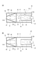
以下、本発明の第2実施形態を図4に基づいて説明する。本実施形態は、上記第1実施形態の混合機構50を変形したものである。図4(A)及び図4(B)に示されるように、本実施形態の混合機構50Vは、ケーシング30の軸方向(即ち、保炎筒26の軸方向)と交差するように配置されたパンチング板61によって構成されている。なお、パンチング板61は、ケーシング30に内接し、ケーシング30とパンチング板61との間には、高温空気Hと低温空気Lが入り込む隙間が形成されていない。
[Second Embodiment]
Hereinafter, a second embodiment of the present invention will be described with reference to FIG. This embodiment is a modification of the
本実施形態では、ケーシング30内の高温空気Hと低温空気Lの流れは、パンチング板61に形成された複数のパンチ孔61Aによって絞られる(図4(A)参照)。これにより、高温空気Hと低温空気Lが混合され易くなり、その結果、乾燥室11に供給される空気の温度のバラつきが抑えられ、不良品の発生が抑制される。なお、本実施形態では、複数のパンチ孔61Aによって、高温空気Hと低温空気Lが通過する通気路の断面積を縮小する圧縮部57Vが形成されている。
In the present embodiment, the flow of the high temperature air H and the low temperature air L in the
なお、本実施形態においても、上記実施形態と同様に、ケーシング30の内部には、区画壁31が設けられていて、混合機構50Vは、ケーシング30内の先端側空間S2に配設されている。詳細には、ケーシング30は、筒形ケース41と延長筒51とで構成され、混合機構50Vは、延長筒51内に配設されている。
In the present embodiment, similarly to the above-described embodiment, the
[第3実施形態]
以下、本発明の第3実施形態を図5に基づいて説明する。本実施形態は、上記第1実施形態の混合機構50を変形したものである。図5(A)及び図5(B)に示されるように、本実施形態では、混合機構50Wは、ケーシング30の軸方向(即ち、保炎筒26の軸方向)と交差するように配置された遮蔽板63によって構成されている。遮蔽板63の面積は、ケーシング30の断面積よりも小さくなっていて、ケーシング30の内周面と遮蔽板63との間には、環状の隙間64が形成されている。なお、遮蔽板63は、ケーシング30の内周面から起立する図示しない支柱にて支持されている。
[Third Embodiment]
Hereinafter, a third embodiment of the present invention will be described with reference to FIG. This embodiment is a modification of the
本実施形態では、燃焼室30内の高温空気Hと低温空気Lは、遮蔽板63を避けるように迂回しながら、ケーシング30の排出口51Aへと流れる。言い換えれば、本実施形態では、遮蔽板63によって、高温空気Hと低温空気Lの流れが迂回させられることとなる。これにより、ケーシング30内で高温空気Hと低温空気Lが流れる通気路を長くすることが可能となり、高温空気Hと低温空気Lが混合され易くなる。
In the present embodiment, the high temperature air H and the low temperature air L in the
また、本実施形態では、ケーシング30内で高温空気Hと低温空気Lが流れる通気路は、遮蔽板63によってケーシング30の径方向外側に狭められることになる。これにより、本実施形態では、高温空気Hと低温空気Lが混合され易くなる。なお、本実施形態では、隙間64によって、高温空気Hと低温空気Lが通過する通気路の断面積を縮小する圧縮部57Wが形成されている。
In the present embodiment, the air passage through which the high temperature air H and the low temperature air L flow in the
なお、本実施形態においても、上記実施形態と同様に、ケーシング30の内部には、区画壁31が設けられていて、混合機構50Wは、ケーシング30内の先端側空間S2に配設されている。詳細には、ケーシング30は、筒形ケース41と延長筒51とで構成され、混合機構50Wは、延長筒51内に配設されている。
In the present embodiment, similarly to the above-described embodiment, the
[第4実施形態]
以下、本発明の第4実施形態を図6に基づいて説明する。本実施形態は、上記第1実施形態の混合機構50を変形したものである。図6(A)及び図6(B)に示されるように、本実施形態の混合機構50Xは、ケーシング30の先端部の内側に備えられた絞り部65によって構成されている。絞り部65は、ケーシング30の先端側へ向かうにつれて縮径される筒状をなしている。なお、図6(A)及び図6(B)に示す例では、絞り部65とケーシング30との間に、隙間が形成されているが、隙間が形成されなくてもよい。
[Fourth Embodiment]
Hereinafter, a fourth embodiment of the present invention will be described with reference to FIG. This embodiment is a modification of the
本実施形態では、ケーシング30内で高温空気Hと低温空気Lが流れる通気路が、絞り部65によって狭められ、これにより、高温空気Hと低温空気Lが混合され易くなる。なお、本実施形態では、絞り部65によって、高温空気Hと低温空気Lが流れる通気路の断面積を縮小する圧縮部57Xが形成されている。
In the present embodiment, the air passage through which the high-temperature air H and the low-temperature air L flow in the
なお、本実施形態においても、上記実施形態と同様に、ケーシング30の内部には、区画壁31が設けられていて、混合機構50Xは、ケーシング30内の先端側空間S2に配設されている。詳細には、ケーシング30は、筒形ケース41と延長筒51とで構成され、混合機構50Xは、延長筒51内に配設されている。図6(A)及び図6(B)に示す例では、混合機構50Xとしての絞り部65が、延長筒51の軸方向全体に亘って配置されている。
In the present embodiment, similarly to the above embodiment, the
[第5実施形態]
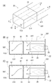
以下、本発明の第5実施形態を図7に基づいて説明する。本実施形態は、上記第1実施形態のケーシング30を変形したものであり、その他の構成については、上記第1実施形態と同様となっている。図7(A)に示すように、本実施形態のケーシング30Yは、下方誘導壁53を内部に備えていない。また、図7(B)及び図7(C)に示すように、ケーシング30Yの軸方向から見たときに、ケーシング30Yの連通口51Aは、区画壁31に形成された連通孔32からずれた位置に配置されている。具体的には、区画壁31の連通孔32は、区画壁31の上側且つ左右方向の一方側に配置されていて、ケーシング30Yの排出口51Aは、筒底壁52の下側且つ左右方向の他方側に配置されている(図7(A)参照)。
[Fifth Embodiment]
Hereinafter, a fifth embodiment of the present invention will be described with reference to FIG. The present embodiment is a modification of the
本実施形態では、区画壁31の連通孔32を通過した高温空気Hと低温空気Lは、先端側空間S2を通って、排出口51Aから排出される。ここで、排出口51Aは、ケーシング30Yの軸方向から見て連通孔32からずれた位置に配置されているので、高温空気Hと低温空気Lは、先端側空間S2内を、ケーシング30Yの軸方向に対して斜めに流れることとなり、連通孔32と排出口51Aが同軸上に配置される場合と比較して、高温空気Hと低温空気Lが流れる通気路が長くなる。これにより、連通孔32を通過した混合空気Hと低温空気Lが先端側空間S2内で混合され易くなる。なお、本実施形態では、混合機構50Yは、ケーシング30Yの軸方向から見て互いにずれて配置される連通孔32及び排出口51Aに連通する先端側空間S2によって構成されている。
In the present embodiment, the high-temperature air H and the low-temperature air L that have passed through the
なお、本実施形態においても、上記実施形態と同様に、ケーシング30は、筒形ケース41Yと延長筒51Yとで構成され、混合機構50Yは、延長筒51Y内に配設されている。
Also in the present embodiment, as in the above-described embodiment, the
[第6実施形態]
以下、本発明の第6実施形態を図8〜図9に基づいて説明する。本実施形態は、上記第1実施形態を変形したものであり、図8に示すように、ケーシング130の構造が上記第1実施形態のケーシング30とは異なっている。以下、ケーシング130の具体的な構成について説明する。
[Sixth Embodiment]
Hereinafter, a sixth embodiment of the present invention will be described with reference to FIGS. The present embodiment is a modification of the first embodiment, and as shown in FIG. 8, the structure of the
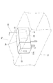
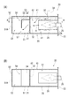
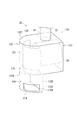
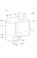
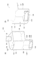
図8及び図9(B)に示すように、ケーシング130は、水平方向(即ち、保炎筒26の軸方向)に沿って延びる水平筒部131の先端部と、鉛直方向に沿って延びる鉛直筒部132の上端部と、が連結された略L字状構造になっている。水平筒部131は、保炎筒26を内側に受容し、水平筒部131の周壁に低温空気導入口33が形成されている(図8及び図9(B)の例では、低温空気導入口33は水平筒部131の上部に形成されている。)。鉛直筒部132は、水平筒部131より下方に突出する下方突部132Kを有している。下方突部132Kには、ケーシング130内の高温空気Hと低温空気Lを排出する排出口51Aが形成されている。
As shown in FIGS. 8 and 9B, the
本実施形態では、鉛直筒部132を軸方向から見た形状は、水平筒部131から遠い側へ膨出する半円形状となっている(図9(A)参照)。また、鉛直筒部132の周壁には、水平筒部131に受容された保炎筒26に先端側から対向する先端対向壁133が形成されていて、鉛直筒部132の内部には、先端対向壁133に沿って延在して、保炎筒26を先端側から覆う遮熱板134が備えられている。遮熱板134は、保炎筒26から流れてくる高温空気Hが先端対向壁133に直撃して先端対向壁133を劣化させること抑制するためのものである。なお、遮熱板134は、鉛直筒部132の天井壁132Tとの間に隙間を有している。これにより、鉛直筒部132内を上方へ移動した高温空気Hが遮熱板134と先端対向壁133との間を通って下方へ移動することができるようになっている。
In the present embodiment, the shape of the vertical
図9(B)に示すように、鉛直筒部132の内部には、遮熱板134のほかに、先端対向壁133から内側に張り出した仕切板135が備えられている。仕切板135は、遮熱板134よりも下方に配置され、先端対向壁133と遮熱板134との間の隙間134Sを下方から覆う。詳細には、図9(A)に示すように、仕切板135の先端対向壁133からの張り出し量は、隙間134Sの幅以上となっている。また、仕切板135は、先端対向壁133の周方向全体に亘って延在している。
As shown in FIG. 9B, in addition to the
なお、本実施形態では、鉛直筒部132の周壁は、上述の先端対向壁133を構成する半円状の円弧壁132Aと、円弧壁132Aのうち保炎筒26を挟むように配置される両端部から保炎筒26の軸方向に延設されて、水平筒部131の周壁に連絡する1対の延長壁132B,132Bと、1対の延長壁132B,132Bの下端部同士を連絡すると共に、水平筒部132の底部先端に連絡する連絡壁132Cと、で構成されている(図8参照)。排出口51Aは、円弧壁132Aの下端部に形成されている。
In the present embodiment, the peripheral wall of the vertical
ケーシング130の構成に関する説明は以上である。なお、本実施形態の塗装用乾燥炉10におけるケーシング130以外の構造については、上記第1実施形態の構造と同様になっているので、同一符号を付すことで説明を省略する。
This completes the description of the configuration of the
次に、本実施形態の塗装用乾燥炉10の作用効果について説明する。本実施形態では、ケーシング130に備えられた低温空気導入口33から低温空気Lがケーシング130内に導入され、バーナ25により加熱された高温空気Hと低温空気Lとが、ケーシング130の先端部に備えられた排出口51Aから排出される。具体的には、低温空気導入口33は、ケーシング130のうち保炎筒26を受容する水平筒部131に備えられていて、ケーシング130においては、高温空気Hと低温空気Lが水平筒部131から鉛直筒部132へと流れる。ここで、排出口51Aは、鉛直筒部132のうち水平筒部131より下方に突出した下方突部132Kに備えられているので、水平筒部131から流れてくる高温空気Hと低温空気Lは、鉛直筒部132内で下方へと移動する。言い換えれば、鉛直筒部132は、高温空気Hと低温空気Lを下方に移動させて、それら高温空気Hと低温空気Lを混合する混合機構150を構成している。
Next, the effect of the
本実施形態によれば、上記実施形態と同様に、ケーシング130内で高温空気Hと低温空気Lとを混合し、その混合後の空気を乾燥室11に供給することが可能となるので、乾燥室11に供給される空気の温度のバラつきを抑えて、不良品の発生を抑制することが可能となる。
According to the present embodiment, as in the above embodiment, it is possible to mix the hot air H and the cold air L in the
また、本実施形態では、鉛直筒部132が水平筒部131から遠い側へ膨出する半円状になっているので、水平筒部131から鉛直筒部132へ流れてきた高温空気Hと低温空気Lを鉛直筒部132の周壁に沿って旋回させて、鉛直筒部132内における高温空気Hと低温空気Lの滞留時間を長くすることが可能となり、高温空気Hと低温空気Lを混合させ易くすることが可能となる。さらに、本実施形態では、鉛直筒部132の上部へと流れて遮熱板134と先端対向壁133(円弧壁132A)との間を下方へと通過する高温空気Hは、仕切板135によって水平筒部131側へと誘導されるので、水平筒部131から流れてくる低温空気Lと混合され易くなる。
Further, in the present embodiment, the vertical
[第7実施形態]
以下、本発明の第7実施形態を図10〜図11に基づいて説明する。本実施形態は、上記第6実施形態のケーシング130を変形したものである。図10及び図11(B)に示すように、本実施形態のケーシング130Vは、水平筒部131Vと鉛直筒部132Vとが連結された略L字状構造になっている。上記第6実施形態と同様に、水平筒部131Vは、保炎筒26を内側に受容し、且つ、低温空気導入口33を備えている。また、鉛直筒部132Vは、水平筒部131Vより下方に突出する下方突部132Kを有し、且つ、その下方突部132Kに排出口51Aを備えている。
[Seventh Embodiment]
Hereinafter, a seventh embodiment of the present invention will be described with reference to FIGS. In the present embodiment, the
本実施形態では、鉛直筒部132Vを軸方向から見た形状が円形状となっている(図11(A)参照)。詳細には、鉛直筒部132Vにおいては、下方突部132Kが円形状に形成されていて、下方突部132Kより上側に配置される部分で構成された上側連結部132Jが、水平筒部131Vから遠い側へ膨出する半円状に形成されている。ここで、水平筒部131における底壁131Bの先端部には、基端側へ膨出する半円状の切欠131Kが形成されていて、その切欠131Kの縁部に、下方突部132Kの周壁のうち水平筒部131に近い側の半円部分が連絡している。
In the present embodiment, the shape of the vertical
また、本実施形態では、ケーシング130Vにおける下方突部132Kの上下方向の長さは、上記第6実施形態のケーシング130における下方突部132Kの上下方向の長さより短くなっている。さらに、本実施形態のケーシング130Vは、鉛直筒部132V内に仕切板135を備えていない点が、上記第6実施形態のケーシング130と異なっている。
In the present embodiment, the vertical length of the
なお、鉛直筒部132Vの上側連結部132Jは、天井壁132Tと、下方突部132Kの周壁から上方に延設された円弧壁132Aと、で構成され、円弧壁132Aの両端部が水平筒部131Vの側壁に連絡している。円弧壁132Aは、保炎筒26に先端側から対向する先端対向壁133を構成する。また、鉛直筒部132V内には、先端対向壁133(円弧壁132A)に沿って延在する遮熱板134が備えられている。
The upper connecting
本実施形態のケーシング130Vの構成に関する説明は以上である。本実施形態によれば、上記第6実施形態と同様の効果を奏することが可能となる。なお、本実施形態では、ケーシング130Vの鉛直筒部132Vが、高温空気Hと低温空気Lを混合する混合機構150Vを構成している。
This is the end of the description of the configuration of the
[他の実施形態]
本発明は、上記実施形態に限定されるものではなく、例えば、以下に説明するような実施形態も本発明の技術的範囲に含まれ、さらに、下記以外にも要旨を逸脱しない範囲内で種々変更して実施することができる。
[Other Embodiments]
The present invention is not limited to the above-described embodiment. For example, the embodiments described below are also included in the technical scope of the present invention, and various modifications are possible within the scope of the invention other than the following. It can be changed and implemented.
(1)上記第1〜第5実施形態では、ケーシング30,30Yは、筒形ケース41,41Yと、延長筒51,51Yと、を別体に備える構成であったが、それらを一体に備える構成であってもよい。即ち、ケーシング30,30Yが1つの筒体で構成されてもよい。この場合、上記第1〜第4実施形態においては、ケーシング30内に区画壁31を備えない構成としてもよい。
(1) In the first to fifth embodiments, the
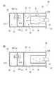
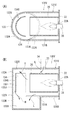
(2)上記第1〜第5実施形態において、連通孔32は、筒形ケース41,41Yの先端部に形成されていればよく、例えば、筒形ケース41,41Yの外周面に形成されていてもよい。なお、その場合、連通孔32の配置に合わせて、延長筒51,51Y及び混合機構50〜50Yのサイズや形状を変更すればよい。なお、図12(A)及び図12(B)には、上記第1実施形態に本構成を適用した場合の一例が示されており、図13(A)及び図13(B)には、上記第2実施形態に本構成を適用した例が示されている。
(2) In the first to fifth embodiments, the
(3)上記実施形態では、低温空気導入口33は、ケーシング30,30Y,130,130Vの上部に配置されていたが、側部に配置されていてもよいし、底部に配置されていてもよい。なお、上記実施形態のように、ケーシング30,30Y,130,130Vの上部に配置される場合には、下方に溜まりやすい低温空気Lが高温空気Hと混合されやすくなる。
(3) In the above embodiment, the low-
(4)上記第1〜第4実施形態において、ケーシング30が、筒底壁52を備えない構成、即ち、ケーシング30の先端側が開放した構成であってもよい。この場合、ケーシング30の先端開口によって、排出口51Aが形成される。
(4) In the first to fourth embodiments, the
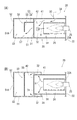
(5)上記第6実施形態において、ケーシング130内に仕切板135を備えない構成としてもよい(図14(A)参照)。また、上記第7実施形態において、仕切板135を備える構成としてもよい。
(5) In the said 6th Embodiment, it is good also as a structure which does not provide the
(6)上記第6,7実施形態において、排出口51Aの開口縁から鉛直筒部132,132Vの内側へ突出する突片136を備えた構成としてもよい(図14(B)参照。なお、同図には、第6実施形態のケーシング130に突片136を備えた例が示されている。)。本構成によれば、高温空気Hと低温空気Lが排出口51Aから排出され難くなり、鉛直筒部132,132V内における高温空気Hと低温空気Lの滞留時間を長くすることが可能となる。なお、突片136は、排出口51Aの開口縁全体から突出してもよいし、一部(例えば、図14(B)における排出口51Aの上縁部と側縁部)から突出してもよい。
(6) In the sixth and seventh embodiments, a configuration may be adopted in which a protruding
10 塗装用乾燥炉
11 乾燥室
15 循環路
25 バーナ
26 保炎筒
30,30Y,130,130V ケーシング
31 区画壁
32 連通孔
33 低温空気導入口
41,41Y 筒形ケース
50,50V,50W,50X,50Y,150,150V 混合機構
51,51Y 延長筒
51A 排出口
53 下方誘導壁
54 上方カバー板
55 先方カバー板
57,57V,57W,57X 圧縮部
61 パンチング板
63 遮蔽板
65 絞り部
131 水平筒部
132 鉛直筒部
134 遮熱板
135 仕切板
H 高温空気
L 低温空気
DESCRIPTION OF
Claims (9)
前記循環路には、前記バーナの炎を囲む保炎筒と、前記保炎筒を外側から囲み且つ前記保炎筒より先端側に突出するケーシングと、が備えられると共に、
前記ケーシングは、外部からの低温空気を前記ケーシング内に導入するための低温空気導入口を備えると共に、前記バーナにより加熱された高温空気と前記低温空気とを前記循環路へ排出するための排出口を先端部に有し、
前記ケーシングに、前記排出口から排出される前の前記高温空気と前記低温空気とを混合する混合機構が設けられている塗装用乾燥炉。 A drying oven for painting in which a circulation path for circulatingly supplying air heated by a burner is connected to a drying chamber to which a painted workpiece is supplied,
The circulation path is provided with a flame holding cylinder that surrounds the flame of the burner, and a casing that surrounds the flame holding cylinder from the outside and protrudes to the front end side from the flame holding cylinder,
The casing includes a low-temperature air inlet for introducing low-temperature air from outside into the casing, and an outlet for discharging the high-temperature air heated by the burner and the low-temperature air to the circulation path. At the tip,
A painting drying furnace in which the casing is provided with a mixing mechanism for mixing the high-temperature air and the low-temperature air before being discharged from the discharge port.
前記区画壁には、前記先端側空間と前記基端側空間とを連通させる連通孔が形成され、
前記混合機構は、前記先端側空間に配置されると共に、前記保炎筒は、前記基端側空間に配置され、
前記低温空気導入口は、前記基端側空間に連通している請求項1乃至3のうち何れか1の請求項に記載の塗装用乾燥炉。 In the casing, a partition wall that divides the internal space of the casing in the axial direction of the flame holding cylinder and divides the space into a distal end side space and a proximal end side space is provided,
The partition wall is formed with a communication hole that communicates the distal end side space and the proximal end side space,
The mixing mechanism is disposed in the distal end side space, and the flame holding cylinder is disposed in the proximal end side space,
The drying furnace for coating according to any one of claims 1 to 3, wherein the low-temperature air introduction port communicates with the base end side space.
前記混合機構は、前記延長筒に設けられている請求項1乃至5のうち何れか1の請求項に記載の塗装用乾燥炉。 The casing has a structure in which an extension cylinder separate from the cylindrical case is attached to a distal end portion of a cylindrical case that houses the flame holding cylinder and includes the low-temperature air inlet,
The coating drying furnace according to any one of claims 1 to 5, wherein the mixing mechanism is provided in the extension cylinder.
前記ケーシングは、前記保炎筒の軸方向に沿って延びる水平筒部の先端部と、鉛直方向に沿って延びる鉛直筒部の上端部と、が連結された構造を有し、
前記水平筒部は、前記保炎筒を内側に受容すると共に、前記低温空気導入口を備え、
前記鉛直筒部は、前記水平筒部より下方に突出する部分に前記排出口を備えて、前記水平筒部から流れてくる前記高温空気と前記低温空気とを下方に移動させるように構成され、
前記混合機構は、前記鉛直筒部によって構成されている請求項1に記載の塗装用乾燥炉。 The flame holding tube extends along a horizontal direction,
The casing has a structure in which a front end portion of a horizontal cylinder portion extending along the axial direction of the flame holding cylinder and an upper end portion of a vertical cylinder portion extending along the vertical direction are connected,
The horizontal cylinder portion receives the flame holding cylinder on the inside, and includes the cold air inlet.
The vertical cylinder portion includes the discharge port in a portion protruding downward from the horizontal cylinder portion, and is configured to move the high temperature air and the low temperature air flowing from the horizontal cylinder portion downward,
The coating drying furnace according to claim 1, wherein the mixing mechanism is configured by the vertical cylinder portion.
前記鉛直筒部のうち前記保炎筒に先端側から対向する先端対向壁に沿って延在して、前記保炎筒を先端側から覆う遮熱板と、
前記遮熱板よりも下方位置で前記先端対向壁から内側に張り出し、前記先端対向壁と前記遮熱板との間の隙間を下方から覆う仕切板と、が備えられている請求項7又は8に記載の塗装用乾燥炉。 In the vertical cylinder part,
A heat shield that extends along the front-facing wall facing the flame-holding cylinder from the tip side of the vertical cylinder portion, and covers the flame-holding cylinder from the tip side;
A partition plate that protrudes inwardly from the tip-facing wall at a position below the heat shield plate and covers a gap between the tip-facing wall and the heat shield plate from below is provided. A drying oven for coating described in 1.
Priority Applications (4)
| Application Number | Priority Date | Filing Date | Title |
|---|---|---|---|
| JP2016080030A JP6788992B2 (en) | 2016-04-13 | 2016-04-13 | Drying furnace for painting |
| US16/086,446 US10690411B2 (en) | 2016-04-13 | 2016-11-15 | Paint drying oven |
| CN201680081381.8A CN108603720B (en) | 2016-04-13 | 2016-11-15 | Drying oven for painting |
| PCT/JP2016/083766 WO2017179234A1 (en) | 2016-04-13 | 2016-11-15 | Paint drying oven |
Applications Claiming Priority (1)
| Application Number | Priority Date | Filing Date | Title |
|---|---|---|---|
| JP2016080030A JP6788992B2 (en) | 2016-04-13 | 2016-04-13 | Drying furnace for painting |
Publications (2)
| Publication Number | Publication Date |
|---|---|
| JP2017190901A true JP2017190901A (en) | 2017-10-19 |
| JP6788992B2 JP6788992B2 (en) | 2020-11-25 |
Family
ID=60041746
Family Applications (1)
| Application Number | Title | Priority Date | Filing Date |
|---|---|---|---|
| JP2016080030A Expired - Fee Related JP6788992B2 (en) | 2016-04-13 | 2016-04-13 | Drying furnace for painting |
Country Status (4)
| Country | Link |
|---|---|
| US (1) | US10690411B2 (en) |
| JP (1) | JP6788992B2 (en) |
| CN (1) | CN108603720B (en) |
| WO (1) | WO2017179234A1 (en) |
Families Citing this family (1)
| Publication number | Priority date | Publication date | Assignee | Title |
|---|---|---|---|---|
| CN112718374B (en) * | 2020-12-25 | 2025-01-28 | 江苏华港医药包装有限公司 | A glue coating and drying integrated machine for producing PET polyester film for packaging bags |
Family Cites Families (13)
| Publication number | Priority date | Publication date | Assignee | Title |
|---|---|---|---|---|
| US3604824A (en) * | 1970-04-27 | 1971-09-14 | Universal Oil Prod Co | Thermal incineration unit |
| US4098567A (en) * | 1976-10-01 | 1978-07-04 | Gladd Industries, Inc. | Recirculating processing oven heater |
| US4441880A (en) * | 1981-04-23 | 1984-04-10 | Pownall Spencer Engineering, Ltd. | Drying apparatus |
| JPS62106680A (en) * | 1985-11-01 | 1987-05-18 | Hitachi Ltd | Laser generator |
| JPH0317974Y2 (en) | 1985-12-25 | 1991-04-16 | ||
| JPS62136735U (en) | 1986-02-21 | 1987-08-28 | ||
| JPH01144605A (en) * | 1987-11-30 | 1989-06-06 | Yoshiden:Kk | Coil |
| JP2514782Y2 (en) | 1988-03-18 | 1996-10-23 | 靖夫 広瀬 | Hot air generator |
| JPH06331274A (en) | 1993-05-25 | 1994-11-29 | Trinity Ind Corp | Auxiliary combustion tube for air heat burner |
| JP3503906B2 (en) | 1993-10-15 | 2004-03-08 | 東京瓦斯株式会社 | Semi-indirect heating melting furnace |
| JPH11276967A (en) | 1998-03-31 | 1999-10-12 | Trinity Ind Corp | Drying oven for painting |
| JP4003186B2 (en) | 2003-09-10 | 2007-11-07 | トリニティ工業株式会社 | Drying system for painting |
| JP2007163117A (en) | 2005-12-16 | 2007-06-28 | Yasunobu Yoshida | Spherical furnace for generating swirl hot air constantly at high temperature |
-
2016
- 2016-04-13 JP JP2016080030A patent/JP6788992B2/en not_active Expired - Fee Related
- 2016-11-15 US US16/086,446 patent/US10690411B2/en not_active Expired - Fee Related
- 2016-11-15 CN CN201680081381.8A patent/CN108603720B/en not_active Expired - Fee Related
- 2016-11-15 WO PCT/JP2016/083766 patent/WO2017179234A1/en not_active Ceased
Also Published As
| Publication number | Publication date |
|---|---|
| CN108603720A (en) | 2018-09-28 |
| CN108603720B (en) | 2020-05-26 |
| US20190101331A1 (en) | 2019-04-04 |
| JP6788992B2 (en) | 2020-11-25 |
| WO2017179234A1 (en) | 2017-10-19 |
| US10690411B2 (en) | 2020-06-23 |
Similar Documents
| Publication | Publication Date | Title |
|---|---|---|
| JP6435058B2 (en) | Burner body lid, burner and gas appliance | |
| US20150107577A1 (en) | Burner | |
| KR101829572B1 (en) | Cylinder for combustor, combustor, and gas turbine | |
| JP2005127705A (en) | Gas turbine engine combustor | |
| KR20160073704A (en) | Burner | |
| US20240377071A1 (en) | Cooking device | |
| JP6948653B2 (en) | Fuel injection device | |
| KR20180101498A (en) | Cooling panels for combustor panels, combustors, combustion devices, gas turbines, and combustor panels | |
| TW201623879A (en) | Combustion device | |
| CN107013912B (en) | Self-cooling injection type combustion device | |
| WO2017179234A1 (en) | Paint drying oven | |
| CN110044626A (en) | A kind of single sector combustor test device | |
| ITMI991207A1 (en) | COMBUSTION CHAMBER FOR GAS TURBINES | |
| CN110088529A (en) | Gas burner and kitchen range including gas burner | |
| JP6148493B2 (en) | Gas burner | |
| KR101573989B1 (en) | Cooking appliance and burner unit | |
| AU2004219830A1 (en) | Gas combustion device | |
| KR20150075523A (en) | Cooking appliance and burner unit | |
| KR102301481B1 (en) | Burner | |
| KR20160073703A (en) | Burner | |
| JP2011214771A (en) | Gas burner unit and gas water heater | |
| AU2004217672A1 (en) | Gas combustion device | |
| JP6178670B2 (en) | Gas burner | |
| JP6072563B2 (en) | Gas burner | |
| CN222316978U (en) | Distributor and combustor |
Legal Events
| Date | Code | Title | Description |
|---|---|---|---|
| A621 | Written request for application examination |
Free format text: JAPANESE INTERMEDIATE CODE: A621 Effective date: 20190219 |
|
| RD04 | Notification of resignation of power of attorney |
Free format text: JAPANESE INTERMEDIATE CODE: A7424 Effective date: 20190315 |
|
| A131 | Notification of reasons for refusal |
Free format text: JAPANESE INTERMEDIATE CODE: A131 Effective date: 20200407 |
|
| A521 | Request for written amendment filed |
Free format text: JAPANESE INTERMEDIATE CODE: A523 Effective date: 20200528 |
|
| TRDD | Decision of grant or rejection written | ||
| A01 | Written decision to grant a patent or to grant a registration (utility model) |
Free format text: JAPANESE INTERMEDIATE CODE: A01 Effective date: 20201027 |
|
| A61 | First payment of annual fees (during grant procedure) |
Free format text: JAPANESE INTERMEDIATE CODE: A61 Effective date: 20201102 |
|
| R150 | Certificate of patent or registration of utility model |
Ref document number: 6788992 Country of ref document: JP Free format text: JAPANESE INTERMEDIATE CODE: R150 |
|
| LAPS | Cancellation because of no payment of annual fees |