JP2017190915A - Gas stove - Google Patents
Gas stove Download PDFInfo
- Publication number
- JP2017190915A JP2017190915A JP2016081117A JP2016081117A JP2017190915A JP 2017190915 A JP2017190915 A JP 2017190915A JP 2016081117 A JP2016081117 A JP 2016081117A JP 2016081117 A JP2016081117 A JP 2016081117A JP 2017190915 A JP2017190915 A JP 2017190915A
- Authority
- JP
- Japan
- Prior art keywords
- point
- button
- extinguishing
- fire
- gas stove
- Prior art date
- Legal status (The legal status is an assumption and is not a legal conclusion. Google has not performed a legal analysis and makes no representation as to the accuracy of the status listed.)
- Granted
Links
Images
Landscapes
- Feeding And Controlling Fuel (AREA)
Abstract
【課題】位置合わせが必要な箇所の数を減らしつつ美観を確保し、隣り合う2つの点消火操作ボタンの一方を操作する際に、意図しないガスバーナに点火されてしまうことのないガスコンロを提供する。【解決手段】一対の点火ボタンの間に、コンロ本体の表面に露出しない態様で仕切部材100を配設し、仕切部材の点消火ボタン02と対向する面に係止凹部171a、171bを設け、係止凹部が配設された面には、移動体(磁石)51a,51bを収納する収納凹部61a,61bを設け、移動体が(a)収納凹部にその全体が収納された収納状態と(b)その一部が係止凹部内に突出する突出状態の、いずれかとなるように移動可能に構成され、一対の点消火ボタンが同時に後方に押し操作されたとき、点消火ボタンの複数の移動体が、両者の間に作用する磁気的吸引力によって突出状態となることで、点消火ボタンが点火操作位置に移動することを牽制する。【選択図】図5[Problem] To provide a gas stove that reduces the number of locations that require alignment, secures a beautiful appearance, and prevents an unintended gas burner from being ignited when one of two adjacent point fire extinguishing operation buttons is operated. . A partition member (100) is arranged between a pair of ignition buttons in such a manner that it is not exposed on the surface of a stove main body, locking recesses (171a, 171b) are provided on the surface of the partition member facing a lighting/extinguishing button (02), Storage recesses 61a and 61b for storing the moving bodies (magnets) 51a and 51b are provided on the surfaces on which the locking recesses are arranged, and the moving bodies are (a) stored in the storage recesses and ( b) a protruding state in which a portion of the extinguishing button protrudes into the locking recess, and a plurality of movements of the extinguishing button when the pair of extinguishing buttons are pushed backward at the same time; The body is in a protruding state due to the magnetic attraction acting between the two, which restrains the movement of the ignition/extinguishing button to the ignition operation position. [Selection drawing] Fig. 5
Description
本発明は、ガスコンロに関し、詳しくは、複数の点消火操作ボタンが並設された構造を有するガスコンロに関する。 The present invention relates to a gas stove, and more particularly to a gas stove having a structure in which a plurality of point-extinguishing operation buttons are arranged in parallel.
ガスコンロには、コンロバーナやグリルバーナなどのガスバーナの点火、消火の操作を行うための点消火操作ボタンをガスコンロ本体の前面に複数並べて配設したガスコンロがある。 Gas stoves include gas stoves in which a plurality of point-fire-extinguishing operation buttons for igniting and extinguishing gas burners such as a stove burner and a grill burner are arranged in front of the gas stove body.
そのようなガスコンロの1つに、特許文献1に開示されているようなガスコンロがある。
このガスコンロは、ガスコンロ本体の前面に横幅方向に隣接して並ぶ点消火ボタンを備えているとともに、2つの点消火ボタンの間には、両者を仕切る中間部材が配設されている。
One such gas stove is a gas stove as disclosed in Patent Document 1.
This gas stove includes a point fire extinguishing button that is arranged adjacent to the front surface of the gas stove main body in the width direction, and an intermediate member that partitions the two is located between the two point fire extinguishing buttons.
したがって、例えば、所定のガスコンロの燃焼を停止しようとした際に、使用者の手指が、燃焼を停止しようとしたガスバーナ用の点消火ボタン(一方側点消火ボタン)と隣り合うガスバーナ用の点消火ボタン(他方側点消火ボタン)に近い領域に近接し、あるいは触れたような場合にも、手指のそれ以上の動作が上記中間部材によって妨げられ、意図せずに他方側点消火ボタンが操作され、ガスバーナに点火されてしまうことを防止することができる。 Thus, for example, when trying to stop the combustion of a predetermined gas stove, the user's finger is pointed out for the gas burner adjacent to the point-off button for the gas burner (one side point-off button) that tried to stop the combustion. Even when it is close to or touching the area close to the button (the other side point fire extinguishing button), further movement of the finger is hindered by the intermediate member, and the other side point fire extinguishing button is operated unintentionally. It is possible to prevent the gas burner from being ignited.
しかしながら、上記特許文献1に開示される中間部材の前端部分の形状は、ガスコンロの横幅方向視において点消火ボタンの前端部分と同じ形状とされていることから、中間部材の前端部分の位置と、中間部材の両側に位置する点消火ボタンの前端部分の位置とが前後方向にずれた場合には、外観上の美観が損なわれることになる。 However, since the shape of the front end portion of the intermediate member disclosed in Patent Document 1 is the same shape as the front end portion of the point-extinguishing button in the horizontal direction of the gas stove, the position of the front end portion of the intermediate member, When the position of the front end portion of the point-extinguishing button located on both sides of the intermediate member is shifted in the front-rear direction, the appearance of the appearance is impaired.
そこで美観が損なわれないようにするためには、中間部材の前端部分(1箇所)の位置と、中間部材の両側に位置する点消火ボタンの前端部分(2箇所)の位置を精度よく合致させる、つまり、3箇所の前端部分の位置を精度よく合致させることが必要となる。
そして、そのためには、製造工程における管理精度を高く保つことが必要になり、生産性の低下やコストの増大を招くという問題点がある。
Therefore, in order not to impair the aesthetic appearance, the position of the front end portion (one place) of the intermediate member and the position of the front end portions (two places) of the point-extinguishing button located on both sides of the intermediate member are matched with each other with high accuracy. In other words, it is necessary to accurately match the positions of the three front end portions.
For this purpose, it is necessary to maintain high management accuracy in the manufacturing process, which causes a problem that productivity is lowered and costs are increased.
本発明は、上記課題を解決するものであり、並設されている複数の点消火ボタンのうち、隣り合う2つの点消火操作ボタンの一方の操作時に、意図せずに使用者の手指が他方の点消火操作ボタンに触れてしまった場合にも、意図しないガスバーナが点火されてしまうことを防止することが可能で、しかも、美観を損なわないようにするために、点消火操作ボタンの前面部などの位置合わせが必要な箇所の数を少なくすることが可能なガスコンロを提供することを目的とする。 The present invention solves the above-mentioned problem, and when a user operates one of two adjacent point-extinguishing buttons among a plurality of point-extinguishing buttons arranged side by side, the user's finger is unintentionally placed on the other side. It is possible to prevent an unintended gas burner from being ignited even if the point fire extinguishing operation button is touched, and in order not to impair the aesthetic appearance, An object of the present invention is to provide a gas stove that can reduce the number of locations that need to be aligned.
上記の目的を達成するために、本発明のガスコンロは、
ガスコンロ本体の横幅方向に並ぶ複数の点消火ボタンが、その消火操作位置において、前記ガスコンロ本体の前面部に設けたボタン装着枠に、前端部分を前記ガスコンロ本体の前方に突出させた状態で設けられ、前記点消火ボタンを押し操作して、前記点消火ボタンを前記消火操作位置から、前記消火操作位置よりも後方の点火操作位置に移動させることにより、前記ガスコンロ本体が備えるガスバーナへの点火が行われるように構成されたガスコンロであって、
前記複数の点消火ボタンのうち、互いに隣り合う少なくとも一対の前記点火ボタンの間には、前記コンロ本体の表面に露出しない態様で仕切部材が配設され、
前記仕切部材の前記点消火ボタンと対向する面には係止凹部が設けられ、
一対の前記点消火ボタンのそれぞれの、前記仕切部材の前記係止凹部が設けられた面と対向する面には、磁石からなる移動体を収納する収納凹部が設けられ、
前記移動体が、(a)前記収納凹部にその全体が収納された収納状態と、(b)その一部が前記係止凹部内に突出した突出状態の、いずれかの状態となるように移動可能に構成され、
前記一対の点消火ボタンが同時に後方に押し操作された場合に、前記点消火ボタンの点火牽制位置において、前記一対の点消火ボタンのそれぞれが備える前記移動体が、両者の間に作用する磁気的吸引力によって前記突出状態となることで、前記点消火ボタンが、前記点火牽制位置から、それより後方の前記点火操作位置に移動することを牽制して、前記ガスバーナへの点火が行われないように構成されていること
を特徴としている。
In order to achieve the above object, the gas stove of the present invention comprises:
A plurality of point fire extinguishing buttons arranged in the width direction of the gas stove body are provided at the fire extinguishing operation position in a state where the front end portion protrudes forward of the gas stove body on the button mounting frame provided on the front part of the gas stove body. The gas burner included in the gas stove main body is ignited by pressing the point fire extinguishing button and moving the point extinguishing button from the fire extinguishing operation position to an ignition operation position behind the fire extinguishing operation position. A gas stove configured to be
Among the plurality of point fire extinguishing buttons, between at least a pair of the ignition buttons adjacent to each other, a partition member is disposed in a manner not exposed on the surface of the stove body,
A locking recess is provided on the surface of the partition member facing the point-extinguishing button,
Each of the pair of point-extinguishing buttons has a storage recess for storing a moving body made of a magnet, on the surface of the partition member facing the surface on which the locking recess is provided.
The movable body moves so as to be in one of the following states: (a) a storage state in which the whole is stored in the storage recess, and (b) a protrusion state in which a part thereof protrudes into the locking recess. Configured and possible
When the pair of point-extinguishing buttons are simultaneously pushed backward, the moving body provided in each of the pair of point-extinguishing buttons acts between the two at the ignition check position of the point-extinguishing button. By being in the protruding state by the suction force, the point-extinguishing button is prevented from moving from the ignition check position to the ignition operation position behind it, so that the gas burner is not ignited. It is characterized by being composed of
本発明のガスコンロにおいては、前記係止凹部の前端壁が、前方から後方に向かって、前記点消火ボタンからの距離が大きくなるような傾斜面とされていることが好ましい。 In the gas stove according to the present invention, it is preferable that the front end wall of the locking recess is inclined so that the distance from the point-extinguishing button increases from the front to the rear.
また、前記点消火ボタンが前記消火操作位置に位置するとき、前記移動体を前記突出状態側から前記収納状態側に向かって磁力により付勢するバイアス磁石を備えていることが好ましい。 Moreover, it is preferable to provide the bias magnet which urges | biases the said mobile body by the magnetic force toward the said accommodation state side from the said protrusion state side when the said point fire extinguishing button is located in the said fire extinguishing operation position.
また、前記バイアス磁石は、前記仕切部材に配設されていることが好ましい。 The bias magnet is preferably disposed on the partition member.
本発明のガスコンロは、上述のように構成されており、複数の点消火ボタンうち、互いに隣り合う少なくとも一対の点火ボタンの間には、ガスコンロ本体の表面に露出しない態様で仕切部材が配設されているので、点消火操作ボタンの前面部の位置などの位置合わせを厳密に行うことが必要な箇所の数を極力抑えつつ、美観を確保することが可能なガスコンロを実現することができる。 The gas stove of the present invention is configured as described above, and among the plurality of point-extinguishing buttons, a partition member is disposed between at least a pair of ignition buttons adjacent to each other so as not to be exposed on the surface of the gas stove body. Therefore, it is possible to realize a gas stove that can ensure aesthetics while minimizing the number of locations that need to be precisely aligned, such as the position of the front portion of the point-extinguishing operation button.
また、仕切部材の点消火ボタンと対向する面には係止凹部が設けられ、点消火ボタンの、上記仕切部材の係止凹部が設けられた面と対向する面には、磁石からなる移動体を収納する収納凹部が設けられ、移動体が、(a)収納凹部にその全体が収納された収納状態と、(b)その一部が係止凹部内に突出する突出状態の、いずれかの状態となるように移動可能に構成され、一対の点消火ボタンが同時に後方に押し操作されたとき、点消火ボタンのそれぞれが備える複数の移動体が、両者の間に作用する磁気的吸引力によって突出状態となることで、点消火ボタンが、点火牽制位置から、それより後方の前記点火操作位置に移動することを牽制するようにしているので、隣り合う二つの点消火操作ボタンのうち、一方の点消火操作ボタンの操作時に、使用者の手指が意図せず他方の点消火操作ボタンに手指が触れてしまった場合にも、意図しないガスバーナが点火されてしまうことを防止することが可能になる。 In addition, a locking recess is provided on the surface of the partition member facing the point fire extinguishing button, and a moving body made of a magnet is provided on the surface of the point fire extinguishing button facing the surface of the partition member provided with the locking recess. The movable body is either one of (a) a storage state in which the entirety is stored in the storage recess, and (b) a protruding state in which a part thereof protrudes into the locking recess. When a pair of point-extinguishing buttons are operated to be pushed backward simultaneously, a plurality of moving bodies provided in each of the point-extinguishing buttons are moved by a magnetic attractive force acting between them. By being in the protruding state, the point-extinguishing button is restrained from moving from the ignition control position to the ignition operation position behind it, so one of the two adjacent point-extinguishing operation buttons Operation of the point fire extinguishing operation button In the case where the finger to the other point extinguishing operation button inadvertently finger of the user had touched, unintended gas burner becomes possible to prevent that is ignited.
また、係止凹部の前端壁を、前方から後方に向かって、点消火ボタンからの距離が大きくなるような傾斜面とすることで、複数の点消火ボタンがともに点火操作位置にある状態から、複数の点消火ボタンを同時に、消火操作位置に向う方向(前方)に移動させた場合、移動体が係止凹部の前方に備える傾斜面(前端壁)に当接し、点消火ボタンの前方への移動によって移動体が徐々に、かつ、確実に収納凹部に収納されるため、点消火ボタンを円滑に消火操作位置に移動させることが可能になる。 Further, by making the front end wall of the locking recess from the front toward the rear, an inclined surface that increases the distance from the point fire button, a plurality of point fire buttons are both in the ignition operation position, When a plurality of point-extinguishing buttons are simultaneously moved in the direction (forward) toward the fire-extinguishing operation position, the moving body comes into contact with an inclined surface (front end wall) provided in front of the locking recess, and the point-extinguishing button is moved forward. Since the moving body is gradually and surely stored in the storage recess by the movement, the point-extinguishing button can be smoothly moved to the fire-extinguishing operation position.
なお、係止凹部の前端壁に上述のような傾斜が付与されていない場合にも、例えば、所定の位置に磁石を配設して、磁気的吸引力により移動体を上記収納凹部に収納されるようにする方法などを適用して、点消火ボタンが円滑に消火操作位置に移動できるように構成することが可能である。 Even when the front end wall of the locking recess is not inclined as described above, for example, a magnet is disposed at a predetermined position, and the moving body is stored in the storage recess by magnetic attraction. By applying such a method, it is possible to configure the point fire extinguishing button so that it can smoothly move to the fire extinguishing operation position.
また、点消火ボタンが前記消火操作位置に位置するとき、移動体を突出状態側から収納状態側に向かって磁力により付勢するバイアス磁石を備えた構成とした場合、点消火ボタンが消火操作位置に位置するとき、移動体を確実に収納状態に維持することが可能になり、信頼性を向上させることができる。 In addition, when the point extinguishing button is located at the extinguishing operation position, when the moving body is configured to include a bias magnet that urges the moving body from the protruding state side toward the stowed state side by the magnetic force, the point extinguishing button is at the extinguishing operation position. When it is positioned at the position, the moving body can be reliably maintained in the housed state, and the reliability can be improved.
また、バイアス磁石を、仕切部材に配設するようにした場合、省スペース化を図ることが可能になり、本発明をより実効あらしめることができる。 Further, when the bias magnet is arranged on the partition member, it is possible to save space and to make the present invention more effective.
以下、本発明の実施形態を示して、その特徴とするところをさらに詳しく説明する。 Hereinafter, the embodiment of the present invention will be shown and the features thereof will be described in more detail.
[実施形態]
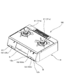
図1に示すように、この実施形態にかかるガスコンロGCは、2口のガステーブルコンロであり、グリルGを備え、グリルG内にはグリルバーナ(図示せず)を備えている。なお、本発明のガスコンロは、ガステーブルコンロに限定されるものではなく、ガスドロップインコンロにも適用可能である。
[Embodiment]
As shown in FIG. 1, the gas stove GC according to this embodiment is a two-port gas table stove, and includes a grill G. The grill G includes a grill burner (not shown). In addition, the gas stove of this invention is not limited to a gas table stove, It is applicable also to a gas drop-in stove.
ガスコンロGCは、ガスコンロ本体Hの上面に2つのコンロバーナ31、すなわち、右コンロバーナ31aと左コンロバーナ31bとを備えている。
The gas stove GC includes two
また、ガスコンロ本体Hの前面部の右側には、右コンロバーナ31aの点消火を行うための点消火ボタン02(02a)と、グリルバーナ(図示せず)の点消火を行うための点消火ボタン02(02b)とが配設されている。
Further, on the right side of the front portion of the gas stove main body H, a point-extinguishing button 02 (02a) for performing point-extinguishing of the
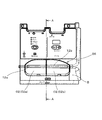
具体的には、右コンロバーナ31aの点消火を行うための点消火ボタン02aと、グリルバーナ(図示せず)の点消火を行うための点消火ボタン02bとは、図2に示すように、二個一で一対として、互いに隣り合うように配設されている。
Specifically, a point-extinguishing
また、ガスコンロ本体Hの前面部の左側には、左コンロバーナ31bの点消火を行うための点消火ボタン02(02c)と、ガスコンロGCが備える制御部(図示せず)の電源となる電池を収納する電池収納部41が配設されている。
Further, on the left side of the front portion of the gas stove main body H, there is a battery serving as a power source for a fire extinguishing button 02 (02c) for performing fire extinguishing of the
次に、右コンロバーナ31(31a)の点消火を行うための点消火ボタン02(02a)と、グリルバーナの点消火を行うための点消火ボタン02(02b)の構成および動作を説明することにより、本発明の特徴とするところをさらに具体的に説明する。 Next, by explaining the configuration and operation of the point-extinguishing button 02 (02a) for performing point-extinguishing of the right burner 31 (31a) and the point-extinguishing button 02 (02b) for performing point-extinguishing of the grill burner The features of the present invention will be described more specifically.
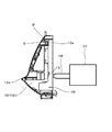
この実施形態のガスコンロGCにおいては、図3に示すように、点消火ボタン02aがその消火操作位置にあるとき、つまり、点消火ボタン02aの消火操作位置においては、コンロバーナ31aへの燃料ガスの通流を制御するガス弁ブロック07が備えるスライダー08が、点消火ボタン02aの後端部13によって後方に押圧されることがないように構成されており、コンロバーナ31aは、燃料ガスが供給されない状態である消火状態に維持される。
In the gas stove GC of this embodiment, as shown in FIG. 3, when the point-extinguishing
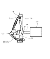
これに対し、図4に示すように、点消火ボタン02aがその点火操作位置にあるとき、つまり、点消火ボタン02aが後方(奥側に)に押し込み操作された、点消火ボタン02aの点火操作位置においては、コンロバーナ31aへの燃料ガスの通流を制御するガス弁ブロック07が備えるスライダー08が、点消火ボタン02aの後端部13によって後方に押圧されて、コンロバーナ31aに燃料ガスが供給される状態である、コンロバーナ31aの点火状態となる。
On the other hand, as shown in FIG. 4, when the
図1、図2、図3、および図4に示すように、コンロ本体Hの横幅方向に並ぶ複数の点消火ボタン02(02a,02b)は、ガスコンロ本体Hの前面部に設けたボタン装着枠B(図2、図3、図4)に対して、その後端側上部13aをコンロ本体Hの横幅方向に沿う軸心Q回りで回動自在に枢支させた状態で、かつ、ガスコンロ本体Hの前面部に設けたボタン挿通用開口06を通して、前端部(点消火ボタン02aの前端部)12aをコンロ前方側に突出させた状態で設けられている。
As shown in FIGS. 1, 2, 3, and 4, a plurality of point-extinguishing buttons 02 (02 a, 02 b) arranged in the horizontal width direction of the stove body H are button mounting frames provided on the front surface of the gas stove body H With respect to B (FIGS. 2, 3 and 4), the rear end side
次に、右コンロ用の点消火ボタン02aおよびおよびグリル用の点消火ボタン02bの動作を規制するための構成や、点消火ボタン02a,02bの動作などについて、詳しく説明する。
Next, the configuration for restricting the operation of the right fire-extinguishing
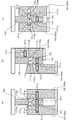
なお、図5(a)は、右コンロ用の点消火ボタン02aおよびグリル用の点消火ボタン02bがともに消火操作位置にある状態を示す図であり、また、図5(b)は、右コンロ用の点消火ボタン02aが消火操作位置にあり、グリル用の点消火ボタン02bが点火操作位置にあるときの状態を示す図である。
FIG. 5 (a) is a diagram showing a state where both the right fire point
さらに、図5(c)は、右コンロ用の点消火ボタン02aおよびグリル用の点消火ボタン02bがともに点火牽制位置にあるときの状態を示す図である。
Further, FIG. 5C is a view showing a state when both the right fire point
ボタン装着枠B(図2〜4)には、右コンロ用の点消火ボタン02aとグリル用の点消火ボタン02bが設けられているとともに、両者の間には、仕切部材100(図5)がガスコンロ本体Hの表面に露出しない態様で設けられている。
The button mounting frame B (FIGS. 2 to 4) is provided with a point-extinguishing
さらに、仕切部材100には、後述のように、右コンロ用の点消火ボタン02aおよびグリル用の点消火ボタン02bの動作を規制するための係止凹部171a,171bが設けられている(図5(a),(b))。
Further, as will be described later, the
また、図5(a),(b)に示すように、係止凹部171a,171bの後端壁172a,172bは、右コンロ用の点消火ボタン02aおよびグリル用の点消火ボタン02bの動作方向(押し込み方向)に直交する面とされており、また、図5(b),(c)に示すように、係止凹部171a,171bの前端壁は、前方から後方に向かって、右コンロ用の点消火ボタン02aおよびグリル用の点消火ボタン02bからの距離が大きくなるような傾斜面173a,173bとされている。
Further, as shown in FIGS. 5A and 5B, the
また、右コンロ用の点消火ボタン02aの、仕切部材100の係止凹部171aが設けられた面と対応する面には、収納凹部61aが設けられており、この収納凹部61aには、移動体(磁石)51aが収納されている。
In addition, a
また、グリル用の点消火ボタン02bの、仕切部材100の係止凹部171bがもうけられた面と対向する面には、収納凹部61bが設けられており、この収納凹部61bには、移動体(磁石)51bが収納されている。
In addition, a
そして、右コンロ用の点消火ボタン02aの、収納凹部61aに収納された移動体(磁石)51aは、収納凹部61a内にその全体が収納された収納状態と、収納凹部61aから係止凹部171aが位置する側に突出する突出状態との間で状態が変化するように、移動可能に構成されている。
また、グリル用の点消火ボタン02bの、収納凹部61bに収納された移動体(磁石)51bは、収納凹部61b内にその全体が収納された収納状態と、収納凹部61bから係止凹部171bが位置する側に突出する突出状態との間で状態が変化するように、移動可能に構成されている。
The moving body (magnet) 51a housed in the
In addition, the moving body (magnet) 51b housed in the
また、ボタン装着枠Bにおける仕切部材100の、右コンロ用の点消火ボタン02aが消火操作位置にあるときの収納凹部61a内に収納された移動体(磁石)51aと対向し、また、グリル用の点消火ボタン02bが消火操作位置にあるときの収納凹部61b内に収納された移動体(磁石)51bと対向する位置には磁石収納凹部161が形成されており、この磁石収納凹部161には、バイアス磁石151が配置されている。
Further, the
バイアス磁石151は、右コンロ用の点消火ボタン02aおよびグリル用の点消火ボタン02bが消火操作位置にあるときに、それぞれの収納凹部61a,61bに収容された移動体(磁石)51a,51bに対して、磁気的な反発力が生じる極性となる態様で、仕切部材100の磁石収納凹部161内に配置されている(図5(a)参照)。すなわち、バイアス磁石151は、N極とS極が、収納凹部61a,61bに収容された移動体(磁石)51a,51bに対して磁気的な反発力が生じるような向きとなるように配設されている。
The
したがって、右コンロ用の点消火ボタン02aおよびグリル用の点消火ボタン02bが消火操作位置にあるとき、それぞれの収納凹部61a,61bに収容された移動体(磁石)51a,51bには、バイアス磁石151の磁力による反発力によって、バイアス磁石151から遠ざかる方向の力が作用する。その結果、移動体(磁石)51a,51bが、収納凹部61a,61b内にその全体が収納された収納状態が確実に維持されることになる。
Therefore, when the right fire-point
また、図5(a)に示す、右コンロ用の点消火ボタン02aおよびグリル用の点消火ボタン02bが消火操作位置にある状態から、右コンロ用の点消火ボタン02aとグリル用の点消火ボタン02bのいずれか一方(ここでは、例えばグリル用の点消火ボタン02b)が押し込み操作されたとき、グリル用の点消火ボタン02bの収容凹部61bに収容された移動体(磁石)51bは、収納状態を維持する。
その結果、グリル用の点消火ボタン02bは、使用者の押し込み操作によって、図5(b)に示す点火操作位置に押し込まれ、グリルバーナが点火することになる。
In addition, from the state in which the right fire-extinguishing
As a result, the grill
また、図5(a)に示す、右コンロ用の点消火ボタン02aおよびグリル用の点消火ボタン02bが消火操作位置にある状態から、右コンロ用の点消火ボタン02aが押し込み操作された場合にも同様の工程を経て右コンロバーナ31aが点火することになる。
Also, when the right-side stove-point fire-extinguishing
これに対し、図5(a)に示す、右コンロ用の点消火ボタン02aおよびグリル用の点消火ボタン02bが消火操作位置にある状態において、右コンロ用の点消火ボタン02aおよびグリル用の点消火ボタン02bの両方が、同時に押し込み操作された場合は、右コンロ用の点消火ボタン02aおよびグリル用の点消火ボタン02bのいずれもが消火操作位置にあるときには、右コンロ用の点消火ボタン02aとグリル用の点消火ボタン02bが備える移動体(磁石)51aと51bが、バイアス磁石151と対向し、バイアス磁石151からの磁気的な反発力で、収納凹部61a,61b内にその全体が収納された収納状態から、図5(c)に示すように、右コンロ用の点消火ボタン02aとグリル用の点消火ボタン02bが備える移動体(磁石)51a,51bが、右コンロ用の点消火ボタン02aおよびグリル用の点消火ボタン02bとともに、後方(奥側)に移動し、移動体(磁石)51a,51bが、バイアス磁石151と対向しない状態となり、右コンロ用の点消火ボタン02aが備える移動体(磁石)51aと、グリル用の点消火ボタン02bが備える移動体(磁石)51bの間に、磁気的な吸引力が生じる。
On the other hand, in the state shown in FIG. 5A in which the right fire-extinguishing
その結果、右コンロ用の点消火ボタン02aとグリル用の点消火ボタン02bは、いずれもが同時に後方(奥側)に押し込まれ、右コンロ用の点消火ボタン02aの移動体(磁石)51aと、グリル用の点消火ボタン02bの移動体(磁石)51bとが係止凹部171a,171bと対向する位置に達すると、移動体(磁石)51aと51bの間に作用する磁気的な吸引力によって、右コンロ用の点消火ボタン02aの移動体(磁石)51aと、グリル用の点消火ボタン02bの移動体(磁石)51bとが係止凹部171a,171bに嵌入する。そして、右コンロ用の点消火ボタン02aおよびグリル用の点消火ボタン02bは、ともに点火牽制位置に至る(図5(c)参照)。
As a result, both of the right fire-extinguishing
そして、図5(c)に示すように、右コンロ用の点消火ボタン02aおよびグリル用の点消火ボタン02bがともに点火牽制位置にある状態から、さらに押し込み操作を継続して、右コンロ用の点消火ボタン02aおよびグリル用の点消火ボタン02bを後方に移動させようとした場合、移動体(磁石)51a,51bが係止凹部171a,171bの後端壁172a,172bに当接して、右コンロ用の点消火ボタン02aおよびグリル用の点消火ボタン02bが、それ以上後方に移動することが阻止される。
Then, as shown in FIG. 5 (c), the pushing operation is further continued from the state where both the right fire point
その結果、図5(a)に示す、右コンロ用の点消火ボタン02aおよびグリル用の点消火ボタン02bがともに消火操作位置にある状態から、両者を同時に操作した場合に、右コンロ用の点消火ボタン02aおよびグリル用の点消火ボタン02bが点火操作位置に移動することが防止される。
As a result, when both the right-pointing point fire-extinguishing
この実施形態のガスコンロは上述のように構成されているので、隣接して配置された右コンロ用の点消火ボタン02aおよびグリル用の点消火ボタン02bのうちの一方を操作する際に、意図せず他方の点消火操作ボタンに使用者の手指が触れてしまった場合にも、意図しないガスバーナが不用意に点火してしまうことを回避することが可能な、信頼性の高いガスコンロを提供することができる。
Since the gas stove of this embodiment is configured as described above, it is not intended when operating one of the right-side stove-point fire-extinguishing
しかも、二つの点消火操作ボタン、すなわち、右コンロ用の点消火ボタン02aおよびグリル用の点消火ボタン02bの間に、従来のガスコンロのように中間部材が表面に露出しないので、美観を確保するために、精度の高い位置合わせを行うことが必要な箇所の数を減らすことが可能になり、コストの増大を抑制しつつ、美観に優れたガスコンロを実現することができる。
In addition, since the intermediate member is not exposed on the surface between the two point fire extinguishing operation buttons, that is, the point
なお、この実施形態にかかるガスコンロにおいては、右コンロ用の点消火ボタン02aおよびグリル用の点消火ボタン02bがともに点火操作位置に押し込まれ、右コンロバーナ31aおよびグリルバーナがともに点火されている状態から、使用者の意図により、右コンロ用の点消火ボタン02aおよびグリル用の点消火ボタン02bを同時に消火操作位置に戻そうとした場合、以下に説明する工程を経て、両者を消火操作位置に戻すことができるように構成されている。
In the gas stove according to this embodiment, both the right fire point
すなわち、この実施形態にかかるガスコンロにおいては、右コンロ用の点消火ボタン02aの移動体(磁石)51a、グリル用の点消火ボタン02bの移動体(磁石)51bとの間に作用する磁気的な吸引力によって、右コンロ用の点消火ボタン02aの移動体(磁石)51aおよびグリル用の点消火ボタン02bの移動体(磁石)51bが、係止凹部171a,171bに嵌入した状態となる。
That is, in the gas stove according to this embodiment, the magnetic body acting between the moving body (magnet) 51a of the
そして、この状態で、右コンロ用の点消火ボタン02aおよびグリル用の点消火ボタン02bを前方へ移動させた場合、右コンロ用の点消火ボタン02aの移動体(磁石)51a、およびグリル用の点消火ボタン02bの移動体(磁石)51bは、係止凹部171a,171bの前端壁である傾斜面173a,173bに当接し、グリル用の点消火ボタン02及び右コンロ用の点消火ボタン02の前方への移動によって、右コンロ用の点消火ボタン02aの移動体(磁石)51a、およびグリル用の点消火ボタン02bの移動体(磁石)51bは、ともに係止凹部171a,171bから脱出し、収納凹部61a,61bに収納される(図5(a))。
Then, in this state, when the point-extinguishing
これにより、右コンロ用の点消火ボタン02aおよびグリル用の点消火ボタン02bは、ともに消火操作位置にある状態に確実に復帰することができる。
Thereby, both the point
なお、上記実施形態において、係止凹部171a,171bの前端壁を傾斜面173a,173bとした構成は任意の構成であり、係止凹部の前端壁を上述のような傾斜面173a,173bとしない場合にも、例えば、所定の位置に磁石を配設して、磁気的吸引力により移動体51a,51bを上記収納凹部61a,61bに収納されるようにする方法などを適用して、点消火ボタンを円滑に動作させるようにすることができる。
In the above embodiment, the front end walls of the locking recesses 171a and 171b are
また、上記実施形態では、右コンロ用の点消火ボタン02aおよびグリル用の点消火ボタン02bが消火操作位置に位置するとき、移動体51a,51bを突出状態側から収納状態側に向かって磁力により付勢するバイアス磁石151を仕切部材100に設けた磁石収納凹部161に配設した場合を例にとって説明したが、バイアス磁石151は、仕切部材100以外の位置に設けることも可能である。また、個々の移動体51a,51b用に複数個のバイアス磁石151を備えた構成とすることも可能である。
Moreover, in the said embodiment, when the point
また、バイアス磁石を備えていない構成とすることも可能である。バイアス磁石を設けることにより、移動体を突出状態側から収納状態側に向かって確実に動作させるようにすることができるが、バイアス磁石を備えていない場合にも、必要な動作をさせることは可能である。 It is also possible to employ a configuration without a bias magnet. By providing a bias magnet, the moving body can be reliably operated from the protruding state side toward the retracted state side. However, even when the bias magnet is not provided, the necessary operation can be performed. It is.
また、上記実施形態では、グリル付きのガスコンロを例にとって説明したが、本発明は、グリルを備えていないガスコンロにも適用することが可能である。 Moreover, although the said embodiment demonstrated taking the gas stove with a grill as an example, this invention is applicable also to the gas stove which is not provided with a grill.
本発明は、さらにその他の点においても、上記実施形態の構成に限定されるものではなく、発明の範囲内において、種々の応用、変形を加えることが可能である。 The present invention is not limited to the configuration of the above embodiment in other points, and various applications and modifications can be added within the scope of the invention.
02 点消火ボタン
02a 右コンロ用の点消火ボタン
02b グリルバーナ用の点消火ボタン
02c 左コンロ用の点消火ボタン
06 ボタン挿通用開口
07 ガス弁ブロック
08 スライダー
12a 右ガスコンロ用の点消火ボタンの前端部
13 右ガスコンロ用の点消火ボタンの後端部
13a 後端側上部
31 コンロバーナ
31a 右コンロバーナ
31b 左コンロバーナ
41 電池収納部
51a,51b 移動体(磁石)
61a,61b 収納凹部
100 仕切部材
151 バイアス磁石
161 磁石収納凹部
171a,171b 係止凹部
172a,172b 係止凹部の後端壁
173a,173b 前端壁の傾斜面
B ボタン装着枠
G グリル
GC ガスコンロ
H ガスコンロ本体
Q 軸心
02
61a,
Claims (4)
前記複数の点消火ボタンのうち、互いに隣り合う少なくとも一対の前記点火ボタンの間には、前記コンロ本体の表面に露出しない態様で仕切部材が配設され、
前記仕切部材の前記点消火ボタンと対向する面には係止凹部が設けられ、
一対の前記点消火ボタンのそれぞれの、前記仕切部材の前記係止凹部が設けられた面と対向する面には、磁石からなる移動体を収納する収納凹部が設けられ、
前記移動体が、(a)前記収納凹部にその全体が収納された収納状態と、(b)その一部が前記係止凹部内に突出した突出状態の、いずれかの状態となるように移動可能に構成され、
前記一対の点消火ボタンが同時に後方に押し操作された場合に、前記点消火ボタンの点火牽制位置において、前記一対の点消火ボタンのそれぞれが備える前記移動体が、両者の間に作用する磁気的吸引力によって前記突出状態となることで、前記点消火ボタンが、前記点火牽制位置から、それより後方の前記点火操作位置に移動することを牽制して、前記ガスバーナへの点火が行われないように構成されていること
を特徴とするガスコンロ。 A plurality of point fire extinguishing buttons arranged in the width direction of the gas stove body are provided at the fire extinguishing operation position in a state where the front end portion protrudes forward of the gas stove body on the button mounting frame provided on the front part of the gas stove body. The gas burner included in the gas stove main body is ignited by pressing the point fire extinguishing button and moving the point extinguishing button from the fire extinguishing operation position to an ignition operation position behind the fire extinguishing operation position. A gas stove configured to be
Among the plurality of point fire extinguishing buttons, between at least a pair of the ignition buttons adjacent to each other, a partition member is disposed in a manner not exposed on the surface of the stove body,
A locking recess is provided on the surface of the partition member facing the point-extinguishing button,
Each of the pair of point-extinguishing buttons has a storage recess for storing a moving body made of a magnet, on the surface of the partition member facing the surface on which the locking recess is provided.
The movable body moves so as to be in one of the following states: (a) a storage state in which the whole is stored in the storage recess, and (b) a protrusion state in which a part thereof protrudes into the locking recess. Configured and possible
When the pair of point-extinguishing buttons are simultaneously pushed backward, the moving body provided in each of the pair of point-extinguishing buttons acts between the two at the ignition check position of the point-extinguishing button. By being in the protruding state by the suction force, the point-extinguishing button is prevented from moving from the ignition check position to the ignition operation position behind it, so that the gas burner is not ignited. A gas stove characterized by being configured as follows.
Priority Applications (1)
| Application Number | Priority Date | Filing Date | Title |
|---|---|---|---|
| JP2016081117A JP6652877B2 (en) | 2016-04-14 | 2016-04-14 | Gas stove |
Applications Claiming Priority (1)
| Application Number | Priority Date | Filing Date | Title |
|---|---|---|---|
| JP2016081117A JP6652877B2 (en) | 2016-04-14 | 2016-04-14 | Gas stove |
Publications (2)
| Publication Number | Publication Date |
|---|---|
| JP2017190915A true JP2017190915A (en) | 2017-10-19 |
| JP6652877B2 JP6652877B2 (en) | 2020-02-26 |
Family
ID=60085909
Family Applications (1)
| Application Number | Title | Priority Date | Filing Date |
|---|---|---|---|
| JP2016081117A Active JP6652877B2 (en) | 2016-04-14 | 2016-04-14 | Gas stove |
Country Status (1)
| Country | Link |
|---|---|
| JP (1) | JP6652877B2 (en) |
Citations (4)
| Publication number | Priority date | Publication date | Assignee | Title |
|---|---|---|---|---|
| JPH02282616A (en) * | 1989-04-22 | 1990-11-20 | San Furonteia Akunorojii:Kk | Igniter for gas utensil |
| JPH0996421A (en) * | 1995-09-29 | 1997-04-08 | Paloma Ind Ltd | Gas table-cooker |
| JP2010196964A (en) * | 2009-02-25 | 2010-09-09 | Rinnai Corp | Gas appliance |
| JP2014224653A (en) * | 2013-05-16 | 2014-12-04 | 東京瓦斯株式会社 | Cooking stove |
-
2016
- 2016-04-14 JP JP2016081117A patent/JP6652877B2/en active Active
Patent Citations (4)
| Publication number | Priority date | Publication date | Assignee | Title |
|---|---|---|---|---|
| JPH02282616A (en) * | 1989-04-22 | 1990-11-20 | San Furonteia Akunorojii:Kk | Igniter for gas utensil |
| JPH0996421A (en) * | 1995-09-29 | 1997-04-08 | Paloma Ind Ltd | Gas table-cooker |
| JP2010196964A (en) * | 2009-02-25 | 2010-09-09 | Rinnai Corp | Gas appliance |
| JP2014224653A (en) * | 2013-05-16 | 2014-12-04 | 東京瓦斯株式会社 | Cooking stove |
Also Published As
| Publication number | Publication date |
|---|---|
| JP6652877B2 (en) | 2020-02-26 |
Similar Documents
| Publication | Publication Date | Title |
|---|---|---|
| KR20180080057A (en) | Cooking Appliance | |
| JP6655330B2 (en) | Stove | |
| JP6652877B2 (en) | Gas stove | |
| JP6763704B2 (en) | Gas stove | |
| JP5116729B2 (en) | grill | |
| JP5330024B2 (en) | Gas appliances | |
| JP6590549B2 (en) | Gas stove | |
| JP2014037930A (en) | Auxiliary ignition tool for lighter | |
| JP6863823B2 (en) | Gas stove | |
| JP6784993B2 (en) | Stove | |
| JP6521774B2 (en) | Operating unit for heating cooker | |
| JP5650701B2 (en) | Thermal power control device | |
| JP4414385B2 (en) | Gas stove | |
| KR20150121653A (en) | Push switch | |
| JP6039295B2 (en) | Cooker | |
| JP6998990B2 (en) | Gas stove | |
| JP2025178562A (en) | Ignition operating device for gas stove and gas stove | |
| JP5121795B2 (en) | grill | |
| JP5395456B2 (en) | Operation lever for cooking device | |
| JP6823951B2 (en) | Gas stove | |
| JP6622999B2 (en) | Cooker with grill | |
| JP6814563B2 (en) | control panel | |
| JP5839540B2 (en) | Lion | |
| JP2020076510A (en) | Stove | |
| JP2022116892A (en) | heating cooker |
Legal Events
| Date | Code | Title | Description |
|---|---|---|---|
| A621 | Written request for application examination |
Free format text: JAPANESE INTERMEDIATE CODE: A621 Effective date: 20190318 |
|
| TRDD | Decision of grant or rejection written | ||
| A01 | Written decision to grant a patent or to grant a registration (utility model) |
Free format text: JAPANESE INTERMEDIATE CODE: A01 Effective date: 20200121 |
|
| A977 | Report on retrieval |
Free format text: JAPANESE INTERMEDIATE CODE: A971007 Effective date: 20200123 |
|
| A61 | First payment of annual fees (during grant procedure) |
Free format text: JAPANESE INTERMEDIATE CODE: A61 Effective date: 20200124 |
|
| R150 | Certificate of patent or registration of utility model |
Ref document number: 6652877 Country of ref document: JP Free format text: JAPANESE INTERMEDIATE CODE: R150 |
|
| R250 | Receipt of annual fees |
Free format text: JAPANESE INTERMEDIATE CODE: R250 |
|
| R250 | Receipt of annual fees |
Free format text: JAPANESE INTERMEDIATE CODE: R250 |
|
| R250 | Receipt of annual fees |
Free format text: JAPANESE INTERMEDIATE CODE: R250 |
|
| R250 | Receipt of annual fees |
Free format text: JAPANESE INTERMEDIATE CODE: R250 |