JP2017191000A - Rod member moving amount detection device - Google Patents
Rod member moving amount detection device Download PDFInfo
- Publication number
- JP2017191000A JP2017191000A JP2016080213A JP2016080213A JP2017191000A JP 2017191000 A JP2017191000 A JP 2017191000A JP 2016080213 A JP2016080213 A JP 2016080213A JP 2016080213 A JP2016080213 A JP 2016080213A JP 2017191000 A JP2017191000 A JP 2017191000A
- Authority
- JP
- Japan
- Prior art keywords
- detection target
- rod member
- shift rod
- detection
- axial direction
- Prior art date
- Legal status (The legal status is an assumption and is not a legal conclusion. Google has not performed a legal analysis and makes no representation as to the accuracy of the status listed.)
- Granted
Links
Images



Landscapes
- Measurement Of Length, Angles, Or The Like Using Electric Or Magnetic Means (AREA)
- Length Measuring Devices With Unspecified Measuring Means (AREA)
- Transmission And Conversion Of Sensor Element Output (AREA)
Abstract
Description
本発明は、ロッド部材の軸方向の移動量を検出するためのロッド部材移動量検出装置に関し、特に、ロッド部材に設けられ、変位センサとの距離がロッド部材の軸方向の移動に対応して変化する検出対象面が形成されている検出対象部を備えるロッド部材移動量検出装置に関する。 The present invention relates to a rod member movement amount detection device for detecting an amount of movement of an axial direction of a rod member, and in particular, is provided on the rod member, and the distance from the displacement sensor corresponds to the movement of the rod member in the axial direction. The present invention relates to a rod member movement amount detection device including a detection target portion on which a changing detection target surface is formed.
従来、車両に設けられる変速機においては、シフトフォークが取り付けられるシフトロッドの位置や移動量を検出することにより変速状態等を把握することが行われている。 2. Description of the Related Art Conventionally, in a transmission provided in a vehicle, a shift state or the like is grasped by detecting a position and a movement amount of a shift rod to which a shift fork is attached.
例えば、シフトロッドの位置を検出する技術としては、2つの検出センサを設けるとともに、シフトロッドに被検出部を設け、2つの検出センサによる被検出部の検出結果のみに基づいて、シフトロッドの位置を検出する技術が知られている(例えば、特許文献1)。 For example, as a technique for detecting the position of the shift rod, two detection sensors are provided, and a detected portion is provided on the shift rod, and the position of the shift rod is determined based only on the detection result of the detected portion by the two detection sensors. There is known a technique for detecting (for example, Patent Document 1).
また、シフトロッドの移動量を検出する技術を用いた装置としては、図5に示すロッド部材移動量検出装置51が知られている。ロッド部材移動量検出装置51は、変位センサ52と、シフトロッド53に設けられ、変位センサ52により距離が検出される対象となる検出対象面55が形成された検出対象部54とを備える。検出対象部54の検出対象面55は、シフトロッド53の軸方向(図中AB方向)の移動に応じて、変位センサ52との距離が変化するように傾斜した平面で構成されている。このため、変位センサ52により検出された検出対象面55との距離に基づいて、シフトロッドの移動距離を検出することができる。
Further, as a device using a technique for detecting the movement amount of the shift rod, a rod member movement
例えば、図5に示すようなロッド部材移動量検出装置51においては、変位センサ52との距離(距離の変化)を検出することにより、シフトロッド53の移動量を検出できるようにしている。
For example, in the rod member movement
このようなロッド部材移動量検出装置51おいては、シフトロッド53は、軸方向に垂直な面での外周の断面が円形状であり、シフトロッド53が軸中心を中心として回転する可能性がある。
In such a rod member movement
シフトロッド53が軸中心を中心として回転してしまうと、検出対象部54の検出対象面55と、変位センサ52との間の距離が変化してしまう。この場合には、変位センサ52により検出される距離には、検出対象面55が回転されてしまったことによる変位センサ52と検出対象面55との距離の変化分も含まれてしまう。このため、変位センサ52により検出された距離に基づいて検出されるシフトロッド53の軸方向の移動量が、シフトロッド53の実際の移動量と乖離してしまう問題がある。
When the
そこで、本発明は、ロッド部材の軸方向の移動量を適切に検出することのできる技術を提供することを目的とする。 Then, an object of this invention is to provide the technique which can detect the moving amount | distance of the axial direction of a rod member appropriately.
上述の目的を達成するため、本発明の一観点に係るロッド部材移動量検出装置は、軸方向に垂直な面での断面の外形が円形状の部分を有するロッド部材の軸方向の移動量を検出するためのロッド部材移動量検出装置であって、所定の検出方向にある部材との間の距離を検出可能なセンサと、軸方向にロッド部材とともに移動可能にロッド部材に設けられ、ロッド部材の軸方向の所定の範囲内の移動時に、センサの検出方向を含む範囲に位置し、センサによるセンサとの間の距離の検出対象となる検出対象面を有する検出対象部と、を備え、検出対象面は、軸方向に垂直な面での断面において、ロッド部材の軸中心から等距離となるように構成され、且つ、軸方向の一端側から他端側にいくほど、ロッド部材の軸中心からの距離が長くなるように構成されている。 In order to achieve the above-described object, a rod member movement amount detection device according to an aspect of the present invention provides a movement amount in the axial direction of a rod member having a circular cross-section in a plane perpendicular to the axial direction. A rod member movement amount detection device for detecting a rod member, which is provided on the rod member so as to be movable together with the rod member in the axial direction and a sensor capable of detecting a distance from a member in a predetermined detection direction. A detection target portion having a detection target surface that is located in a range including the detection direction of the sensor and is a detection target of a distance between the sensor and the sensor when moving within a predetermined range in the axial direction of The target surface is configured to be equidistant from the axial center of the rod member in a cross section taken along a plane perpendicular to the axial direction, and the axial center of the rod member increases from one end side to the other end side in the axial direction. So that the distance from It is configured.
上記ロッド部材移動量検出装置において、検出対象面は、軸方向に垂直な面での断面において、ロッド部材の外周を囲む円形状に形成されていてもよい。 In the rod member movement amount detection device, the detection target surface may be formed in a circular shape surrounding the outer periphery of the rod member in a cross section taken along a plane perpendicular to the axial direction.
また、上記ロッド部材移動量検出装置において、検出対象面の軸方向の一端側における軸方向に垂直な面での断面において、ロッド部材の軸中心から検出対象面までの距離が、一端側に接続されているロッド部材の半径より短くてもよい。 Further, in the rod member movement amount detection device, the distance from the axial center of the rod member to the detection target surface is connected to the one end side in the cross section of the detection target surface in the axial direction at one end side in the axial direction. It may be shorter than the radius of the rod member.
また、上記ロッド部材移動量検出装置において、検出対象面は、軸方向に垂直な面での断面において、円弧状に形成されていてもよい。 In the rod member movement amount detection device, the detection target surface may be formed in an arc shape in a cross section taken along a plane perpendicular to the axial direction.
また、上記ロッド部材移動量検出装置において、検出対象部は、内周に形成された貫通孔にロッド部材を挿通させて検出対象部をロッド部材に固定するための固定部と、検出対象面を構成する薄板状の曲面部と、固定部と曲面部とを連結する連結部とを備えるようにしてもよい。 In the rod member movement amount detection device, the detection target unit includes a fixing unit for inserting the rod member into a through hole formed in the inner periphery and fixing the detection target unit to the rod member, and a detection target surface. You may make it comprise the thin-plate-shaped curved surface part to comprise, and the connection part which connects a fixing | fixed part and a curved surface part.
また、上記ロッド部材移動量検出装置において、検出対象部と、ロッド部材とが一体成形されていてもよい。 In the rod member movement detection device, the detection target portion and the rod member may be integrally formed.
また、上記ロッド部材移動量検出装置において、センサは、検出方向に磁束を発生させることにより検出方向の部材との間の距離を検出する渦電流式の変位センサであり、検出対象部の検出対象面を構成する部材は、導電体であってもよい。 In the rod member movement amount detection device, the sensor is an eddy current type displacement sensor that detects a distance from a member in the detection direction by generating a magnetic flux in the detection direction, and is a detection target of the detection target portion. The member constituting the surface may be a conductor.
本発明によれば、ロッド部材の軸方向の移動量を適切に検出することができる。 According to the present invention, it is possible to appropriately detect the amount of movement of the rod member in the axial direction.
以下、添付図面に基づいて、本発明の一実施形態に係るロッド部材移動量検出装置の一例であるシフトロッド移動量検出装置を説明する。同一の部品には同一の符号を付してあり、それらの名称および機能も同じである。したがって、それらについての詳細な説明は繰返さない。 Hereinafter, a shift rod movement amount detection device that is an example of a rod member movement amount detection device according to an embodiment of the present invention will be described with reference to the accompanying drawings. The same parts are denoted by the same reference numerals, and their names and functions are also the same. Therefore, detailed description thereof will not be repeated.
図1(a)は、本発明の第1実施形態に係るシフトロッド移動量検出装置の斜視図であり、図1(b)は、本発明の第1実施形態に係るシフトロッド移動量検出装置の一部の側面図である。図1(b)は、図1(a)のA方向からシフトロッド移動量検出装置を見た側面図である。 FIG. 1A is a perspective view of a shift rod movement amount detection device according to the first embodiment of the present invention, and FIG. 1B is a shift rod movement amount detection device according to the first embodiment of the present invention. FIG. FIG.1 (b) is the side view which looked at the shift rod movement amount detection apparatus from the A direction of Fig.1 (a).
シフトロッド移動量検出装置11は、車両に備えられる変速機において、内部のシャフトと変速ギヤとの係合/非係合を行うために変速機構を移動させるためのシフトロッド13のシフト方向(図1(a)AB方向)の移動量を検出するための装置である。シフトロッド移動量検出装置11は、変位センサ12と、ロッド部材の一例としてのシフトロッド13と、検出対象部14と、コントロールユニット19とを備える。
The shift rod movement
シフトロッド13は、例えば、円柱状又は円筒状の軸方向(図1(a)AB方向)に垂直な断面での外形が円形状の部分を有する部材である。シフトロッド13は、例えば、半径r0の軸部分を有する。シフトロッド13には、図示しない変速機構のスリーブの外周に係合される図示しないシフトフォークが固定される。シフトロッド13は、図示しないガイドにより、軸方向に移動可能に支持される。ガイドは、例えば、シフトロッド13の軸方向に垂直な断面での外形が円形状の部分の全周または一部と接触してシフトロッド13の軸方向の移動を案内する。また、シフトロッド13は、例えば、図示しないアクチュエータにより、軸方向に移動される。
The
変位センサ12は、所定の検出方向(本実施形態では、検出センサ12の軸方向)に存在する部材との距離、変位を検出するセンサである。変位センサ12は、例えば、検出方向に対して磁束を発生させて、検出方向の部材に渦電流を生じさせ、その渦電流に起因する状態に関する情報を検出することにより、検出方向の部材との間の距離を検出する渦電流式の変位センサである。本実施形態では、変位センサ12の検出方向は、シフトロッド13の軸方向に垂直な面内において、鉛直下向きとなる様に調整されている。なお、変位センサ12の検出方向は、検出対象部14の検出対象面15を用いて距離を検出することのできる方向であれば、この方向に限られない。
The
検出対象部14は、例えば、鉄、アルミニウム等の導電体により、円錐台状に形成されている。検出対象部14の外側面、すなわち、円錐台の側面は、変位センサ12により間隔が検出される検出対象面15となっている。検出対象部14には、検出対象部14の中心軸に沿ってシフトロッド13が挿通される貫通孔18が形成されている。検出対象部14は、貫通孔18にシフトロッド13が挿通された後に、図示しないピン等によりシフトロッド13に軸方向に一体移動可能なように固定される。
The
検出対象部14がシフトロッド13に固定された状態では、検出対象面15は、A方向側の端に位置する第1端部16においては、シフトロッド13の軸に垂直な面での断面において、シフトロッド13の軸中心Oから検出対象面15までの距離が等距離(半径r1:r1>r0)の円形状となるように構成されている。また、検出対象面15は、第1端部16からB方向側にいくに従って、シフトロッド13の軸に垂直な面での断面において、シフトロッド13の軸中心Oから検出対象面15までの距離が徐々に長くなるように構成され、B方向側の端に位置する第2端部17においては、シフトロッド13の軸に垂直な面での断面において、シフトロッド13の軸中心Oから検出対象面15までの距離が等距離(半径r2:r2>r1)の円形状となるように構成されている。この検出対象部14では、シフトロッド13の第1端部16から第2端部17との間の軸方向の距離の範囲内での移動距離を検出できる。
In a state in which the
本実施形態では、上述のように変位センサ12の検出方向は、鉛直下向きに位置合わせされており、シフトロッド13が軸方向に移動した場合には、変位センサ12の検出方向の中心は、図1(b)の線ML上を移動するようになっている。この際には、シフトロッド13が軸方向に移動すると、変位センサ12と検出対象面15との間の距離が移動に応じて変化して検出される。
In the present embodiment, as described above, the detection direction of the
コントロールユニット19は、公知のCPU、ROM、RAM、入力ポート、出力ポート等を備える。コントロールユニット19は、変位センサ12からのセンサ値(変位センサ12から検出対象面15までの距離)に基づいて、シフトロッド13の軸方向の移動距離を検出する。例えば、コントロールユニット19の図示しないメモリに、変位センサ112から検出対象面15までの距離と、シフトロッド13の軸方向の所定の基準位置からの移動距離との対応関係を記憶しておき、コントロールユニット19は、センサ値から対応するシフトロッド13の移動距離を特定するようにしてもよい。
The
以上説明したように、第1実施形態に係るシフトロッド移動量検出装置11は、シフトロッド13の軸に垂直な面での断面において、シフトロッド13の軸中心Oから検出対象面15までの距離が等距離となっているので、シフトロッド13及び検出対象部14が軸中心Oを中心に回転したとしても、シフトロッド13の軸中心Oと、検出対象面15との距離が変化しない。このため、変位センサ12と、変位センサ12の検出方向にある検出対象面15との間の距離が、シフトロッド13及び検出対象部14の軸中心Oを中心とする回転が発生しても変化しない。このため、シフトロッド13及び検出対象部14の軸中心Oを中心とする回転が発生しても、変位センサ12から出力されるセンサ値に変化がなく、シフトロッド13の軸方向の移動量に影響を与えない。したがって、シフトロッド13及び検出対象部14の軸中心Oを中心とする回転の影響を受けずに、シフトロッド14の軸方向の移動量を適切に検出することができる。
As described above, the shift rod moving
次に、本発明の第2実施形態に係るシフトロッド移動量検出装置について説明する。なお、ここでは、第1実施形態と異なる点について説明する。 Next, a shift rod movement amount detection apparatus according to the second embodiment of the present invention will be described. Here, differences from the first embodiment will be described.
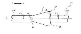
図2は、本発明の第2実施形態に係るシフトロッド移動量検出装置の一部の斜視図である。 FIG. 2 is a perspective view of a part of the shift rod movement amount detection device according to the second embodiment of the present invention.
第2実施形態に係るシフトロッド移動量検出装置は、シフトロッド23を有する。シフトロッド23は、第1シフトロッド部23Aと、検出対象部24と、第2シフトロッド部23Bとを備える。シフトロッド23は、例えば、一体成形されている。
The shift rod movement amount detection device according to the second embodiment has a
第1シフトロッド部23Aは、半径r0の円柱状部材であり、検出対象部24の第1端部26と接続されている。第2シフトロッド部23Bは、半径r0の円柱状部材であり、検出対象部24の第2端部27と接続されている。
The first
検出対象部24は、例えば、円錐台状に形成されている。検出対象部24の外側面、すなわち、円錐台の側面は、変位センサ12により間隔が検出される検出対象面25となっている。
The
検出対象部24の検出対象面25は、A方向側の端に位置する第1端部26においては、シフトロッド23の軸に垂直な面での断面において、シフトロッド23の軸中心Oから検出対象面25までの距離が等距離(半径r3:第1シフトロッド部23Aの半径r0よりも短い(r0>r3))の円形状となるように構成されている。また、検出対象面25は、第1端部26からB方向側にいくに従って、シフトロッド23の軸に垂直な面での断面において、シフトロッド23の軸中心Oから検出対象面25までの距離が徐々に長くなるように構成され、B方向側の端に位置する第2端部27においては、シフトロッド23の軸に垂直な面での断面において、シフトロッド23の軸中心Oから検出対象面25までの距離が等距離(半径r4:r4>r3)の円形状となるように構成されている。なお、本実施形態では、変位センサ12の検出方向は、変位センサ12の検出方向の中心が、検出対象面25上となる様に位置合わせされる。
The
第2実施形態に係るシフトロッド移動量検出装置によると、検出対象部24の第1端部26の半径r3を、第1シフトロッド部23Aの半径r0よりも短くしたので、検出対象部24のサイズを小型できたり、或いは、検出対象部24のサイズを抑えつつ、第1端部26と第2端部27の半径の差を大きくしたりすることができる。例えば、検出対象部24の第1端部26と第2端部27との半径の差を第1実施形態の第1端部16と第2端部17との半径の差と同様にした場合において、検出対象部24の大きさを、第1実施形態の検出対象部14よりも小さくすることができる。また、検出対象部24の最大径の部分の大きさを第1実施形態の検出対象部14と同じにすると、第1端部26と第2端部27との半径の差を第1実施形態の第1端部16と第2端部17との半径の差よりも大きくすることができ、検出センサ12による検出精度を向上することができる。
According to the shift rod movement amount detection device according to the second embodiment, the radius r3 of the
次に、本発明の第3実施形態に係るシフトロッド移動量検出装置について説明する。なお、ここでは、第1実施形態と異なる点について説明する。 Next, a shift rod movement amount detection device according to a third embodiment of the present invention will be described. Here, differences from the first embodiment will be described.
図3(a)は、本発明の第3実施形態に係るシフトロッド移動量検出装置の斜視図である。図3(b)は、本発明の第3実施形態に係るシフトロッド移動量検出装置の一部の側面図である。図3(b)は、図3(a)のA方向からシフトロッド移動量検出装置を見た側面図である。 FIG. 3A is a perspective view of a shift rod movement amount detection device according to the third embodiment of the present invention. FIG. 3B is a side view of a part of the shift rod movement amount detection device according to the third embodiment of the present invention. FIG.3 (b) is the side view which looked at the shift rod movement amount detection apparatus from the A direction of Fig.3 (a).
検出対象部34は、例えば、鉄、アルミニウム等の導電体により、一体成形されている。検出対象部34は、固定部38と、曲面部40と、連結部39とを備える。固定部38は、内周にシフトロッド13が挿通される貫通孔が形成されている。固定部38は、貫通孔にシフトロッド13が挿通された後に、図示しないピン等によりシフトロッド13に軸方向に一体移動可能なように固定される。曲面部40は、変位センサ12により間隔が検出される検出対象面35を構成する薄板状の部材である。検出対象面35は、円錐台の側面の一部に相当する。連結部39は、固定部38と、曲面部40とを連結する部材である。
The
検出対象面35は、A方向側の端に位置する第1端部36においては、シフトロッド13の軸に垂直な面での断面において、シフトロッド13の軸中心Oから検出対象面35までの距離が等距離(半径r5:r5>r0)の円弧状となるように構成されている。本実施形態では、検出対象面35の円弧は、検出センサ12の設計上の検出方向の中心に対応する位置(線ML上の位置)を挟んだ両側の範囲を含むように形成されている。なお、円弧の形成範囲は、シフトロッド13が回転しても、検出対象面35の何れかの部分が検出センサ12の検出方向の中心にあることが保証されるように決めればよい。
In the
また、検出対象面35は、第1端部36からB方向側にいくに従って、シフトロッド13の軸に垂直な面での断面において、シフトロッド13の軸中心Oから検出対象面35までの距離が徐々に長くなるように構成され、B方向側の端に位置する第2端部37においては、シフトロッド13の軸に垂直な面での断面において、シフトロッド13の軸中心Oから検出対象面35までの距離が等距離(半径r6:r6>r5)の円弧状となるように構成されている。本実施形態では、検出対象面35の円弧は、検出センサ12の設計上の検出方向の中心に対応する位置(線ML上の位置)を挟んだ両側の範囲も含むように形成されている。なお、円弧の形成範囲は、シフトロッド13が回転しても、検出対象面35の何れかの部分が検出センサ12の検出方向の中心にあることが保証されるように決めればよい。
Further, the
本実施形態では、上述のように変位センサ12の検出方向は、鉛直下向きに位置合わせされており、シフトロッド13が軸方向に移動した場合には、変位センサ12の検出方向の中心は、図3(b)の線ML上を移動するようになっている。この際には、シフトロッド13が軸方向に移動すると、変位センサ12と検出対象面35との間の距離が移動に応じて変化して検出される。
In the present embodiment, as described above, the detection direction of the
第3実施形態に係るシフトロッド移動量検出装置によると、検出対象面35を薄板状の曲面部40で構成するとともに、検出対象面35を円弧状としたので、検出対象部34を軽量化することができる。また、検出対象面35を円形状ではなくて、円弧状としたので、検出対象部34の移動を確保するためにシフトロッド13の周囲に必要な領域を低減することができる。
According to the shift rod moving amount detection device according to the third embodiment, the
次に、本発明の第4実施形態に係るシフトロッド移動量検出装置について説明する。なお、ここでは、第1実施形態と異なる点について説明する。 Next, a shift rod moving amount detection apparatus according to a fourth embodiment of the present invention will be described. Here, differences from the first embodiment will be described.
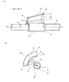
図4(a)は、本発明の第4実施形態に係るシフトロッド移動量検出装置の斜視図である。図4(b)は、本発明の第4実施形態に係るシフトロッド移動量検出装置の一部の側面図である。図4(b)は、図4(a)のA方向からシフトロッド移動量検出装置を見た側面図である。 FIG. 4A is a perspective view of a shift rod movement amount detection device according to the fourth embodiment of the present invention. FIG. 4B is a side view of a part of the shift rod movement amount detection device according to the fourth embodiment of the present invention. FIG. 4B is a side view of the shift rod movement amount detection device viewed from the direction A in FIG.
検出対象部44は、例えば、鉄、アルミニウム等の導電体により、一体成形されている。検出対象部44は、固定部48と、曲面部49とを備える。固定部48は、内周にシフトロッド13が挿通される貫通孔が形成されている。固定部48は、貫通孔にシフトロッド13が挿通された後に、図示しないピン等によりシフトロッド13に軸方向に一体移動可能なように固定される。曲面部49は、変位センサ12により間隔が検出される検出対象面45を構成する部材である。曲面部49は、円錐台を軸中心に所定の中心角に相当する部分を取り出した形状(部分円錐台)に相当する。
The
検出対象面45は、A方向側の端に位置する第1端部46においては、シフトロッド13の軸に垂直な面での断面において、シフトロッド13の軸中心Oから検出対象面45までの距離が等距離(半径r5:r5>r0)の円弧状となるように構成されている。本実施形態では、検出対象面45の円弧は、検出センサ12の設計上の検出方向の中心に対応する位置(線ML上の位置)を挟んだ両側の範囲を含むように形成されている。円弧の形成範囲は、シフトロッド13が回転しても、検出対象面45の何れかの部分が検出センサ12の検出方向の中心にあることが保証されるように決めればよい。
The
また、検出対象面45は、第1端部46からB方向側にいくに従って、シフトロッド13の軸に垂直な面での断面において、シフトロッド13の軸中心Oから検出対象面45までの距離が徐々に長くなるように構成され、B方向側の端に位置する第2端部47においては、シフトロッド13の軸に垂直な面での断面において、シフトロッド13の軸中心Oから検出対象面45までの距離が等距離(半径r6:r6>r5)の円弧状となるように構成されている。本実施形態では、検出対象面45の円弧は、検出センサ12の設計上の検出方向の中心に対応する位置(線ML上の位置)を挟んだ両側の範囲を含むように形成されている。なお、円弧の形成範囲は、シフトロッド13が回転しても、検出対象面45の何れかの部分が検出センサ12の検出方向の中心にあることが保証されるように決めればよい。
Further, the
本実施形態では、上述のように変位センサ12の検出方向は、鉛直下向きに位置合わせされており、シフトロッド13が軸方向に移動した場合には、変位センサ12の検出方向の中心は、図4(b)の線ML上を移動するようになっている。この際には、シフトロッド13が軸方向に移動すると、変位センサ12と検出対象面45との間の距離が移動に応じて変化して検出される。
In the present embodiment, as described above, the detection direction of the
第4実施形態に係るシフトロッド移動量検出装置によると、検出対象面45を部分円錐台で構成するようにしたので、検出対象部45を円錐台で構成する場合に比して軽量化することができ、検出対象部44の移動を確保するためにシフトロッド13の周囲に必要な領域を低減することができる。
According to the shift rod movement amount detection device according to the fourth embodiment, the
なお、本発明は、上述の実施形態に限定されるものではなく、本発明の趣旨を逸脱しない範囲で、適宜変形して実施することが可能である。 In addition, this invention is not limited to the above-mentioned embodiment, In the range which does not deviate from the meaning of this invention, it can change suitably and can implement.
例えば、上記実施形態では、ロッド部材の一例としてシフトロッドを用いて説明していたが、これに限られず、軸方向へ移動するロッド部材であれば、本発明を適用することができる。 For example, in the above embodiment, the shift rod is used as an example of the rod member. However, the present invention is not limited to this, and the present invention can be applied to any rod member that moves in the axial direction.
また、上記実施形態では、変位センサとして、渦電流式の変位センサを例に用いていたが、本発明はこれに限られず、変位センサとしては、例えば、光(レーザ)を用いて対象物との距離を検出する光学式の変位センサや、超音波を用いて対象物との距離を検出する超音波式の変位センサや、接触式の変位センサを用いてもよい。なお、変位センサと、検出対象面との位置関係については、変位センサの検出原理に合わせて調整すればよい。例えば、光学式の変位センサであって、検出対象面に垂直に投光し、拡散反射光を受光して距離を検出する拡散反射光方式の変位センサであれば、変位センサの投光する光軸を、シフトロッド13の軸中心Oに向けるように調整すればよい。また、検出対象面を構成する部材についても、使用する変位センサの検出原理に合わせて決定すればよい。
In the above embodiment, an eddy current type displacement sensor is used as an example of the displacement sensor. However, the present invention is not limited to this, and the displacement sensor may be, for example, an object using light (laser). Alternatively, an optical displacement sensor that detects the distance of the object, an ultrasonic displacement sensor that detects the distance to the object using ultrasonic waves, or a contact displacement sensor may be used. The positional relationship between the displacement sensor and the detection target surface may be adjusted according to the detection principle of the displacement sensor. For example, if the displacement sensor is an optical displacement sensor that projects light perpendicular to the detection target surface and receives diffuse reflection light to detect the distance, the light emitted by the displacement sensor is used. What is necessary is just to adjust an axis | shaft so that it may face the axial center O of the
また、上記第3実施形態では、検出対象面35を軸方向に垂直な面での断面において、シフトロッド13の軸中心Oから検出対象面35までの距離が等距離の円弧状となるように構成されていたが、本発明はこれに限られず、軸方向に垂直な面での断面において円形状となる様に構成してもよい。このようにすると、検出対象部を第1実施形態のように円錐台状に形成する場合に比して、検出対象部を軽量化することができる。
Further, in the third embodiment, the distance from the axial center O of the
また、上記第1、第3、及び第4実施形態では、シフトロッドと、検出対象部とを別体で形成し、その後、固定するようにしているが、本発明はこれに限られず、シフトロッドと検出対象部とを一体成形するようにしてもよい。 In the first, third, and fourth embodiments, the shift rod and the detection target part are formed separately and then fixed. However, the present invention is not limited to this, and the shift is performed. The rod and the detection target part may be integrally formed.
11 シフトロッド移動量検出装置
12 変位センサ
13,23 シフトロッド
14,24,34,44 検出対象部
15,25,35,45 検出対象面
16,26,36,46 第1端部
17,27,37,47 第2端部
19 コントロールユニット
38,48 固定部
39 連結部
40,49 曲面部
DESCRIPTION OF
Claims (7)
所定の検出方向にある部材との間の距離を検出可能なセンサと、
前記軸方向に前記ロッド部材とともに移動可能に前記ロッド部材に設けられ、前記ロッド部材の前記軸方向の所定の範囲内の移動時に、前記センサの前記検出方向を含む範囲に位置し、前記センサによる前記センサとの間の距離の検出対象となる検出対象面を有する検出対象部と、を備え、
前記検出対象面は、前記軸方向に垂直な面での断面において、前記ロッド部材の軸中心から等距離となるように構成され、且つ、前記軸方向の一端側から他端側にいくほど、前記ロッド部材の軸中心からの距離が長くなるように構成されている
ロッド部材移動量検出装置。 A rod member movement amount detection device for detecting the amount of movement in the axial direction of a rod member having a circular outer portion of a cross section in a plane perpendicular to the axial direction,
A sensor capable of detecting a distance between a member in a predetermined detection direction;
It is provided in the rod member so as to be movable together with the rod member in the axial direction, and is located in a range including the detection direction of the sensor when the rod member moves within a predetermined range in the axial direction. A detection target portion having a detection target surface that is a detection target of the distance between the sensor, and
The detection target surface is configured to be equidistant from the axial center of the rod member in a cross section in a plane perpendicular to the axial direction, and as it goes from one end side to the other end side in the axial direction, A rod member movement amount detection device configured to increase a distance from an axial center of the rod member.
請求項1に記載のロッド部材移動量検出装置。 2. The rod member movement amount detection device according to claim 1, wherein the detection target surface is formed in a circular shape surrounding an outer periphery of the rod member in a cross section taken along a plane perpendicular to the axial direction.
請求項2に記載のロッド部材移動量検出装置。 The rod connected to the one end side by a distance from the axial center of the rod member to the detection target surface in a cross section of a plane perpendicular to the axial direction on one end side in the axial direction of the detection target surface The rod member movement amount detection device according to claim 2, which is shorter than a radius of the member.
請求項1に記載のロッド部材移動量検出装置。 The rod member movement amount detection device according to claim 1, wherein the detection target surface is formed in an arc shape in a cross section taken along a plane perpendicular to the axial direction.
請求項1から請求項4の何れか一項に記載のロッド部材移動量検出装置。 The detection target portion includes a fixing portion for fixing the detection target portion to the rod member by inserting the rod member through a through hole formed in an inner periphery, and a thin plate-like curved surface constituting the detection target surface The rod member movement amount detection device according to any one of claims 1 to 4, further comprising a connecting portion that connects the fixing portion and the curved portion.
請求項1から請求項5の何れか一項に記載のロッド部材移動量検出装置。 The rod member movement amount detection device according to any one of claims 1 to 5, wherein the detection target portion and the rod member are integrally formed.
前記検出対象部の前記検出対象面を構成する部材は、導電体である
請求項1から請求項6の何れか一項に記載のロッド部材移動量検出装置。 The sensor is an eddy current type displacement sensor that detects a distance from a member in the detection direction by generating a magnetic flux in the detection direction;
The rod member movement amount detection device according to any one of claims 1 to 6, wherein a member constituting the detection target surface of the detection target portion is a conductor.
Priority Applications (1)
| Application Number | Priority Date | Filing Date | Title |
|---|---|---|---|
| JP2016080213A JP6747027B2 (en) | 2016-04-13 | 2016-04-13 | Rod member movement amount detection device |
Applications Claiming Priority (1)
| Application Number | Priority Date | Filing Date | Title |
|---|---|---|---|
| JP2016080213A JP6747027B2 (en) | 2016-04-13 | 2016-04-13 | Rod member movement amount detection device |
Publications (2)
| Publication Number | Publication Date |
|---|---|
| JP2017191000A true JP2017191000A (en) | 2017-10-19 |
| JP6747027B2 JP6747027B2 (en) | 2020-08-26 |
Family
ID=60085100
Family Applications (1)
| Application Number | Title | Priority Date | Filing Date |
|---|---|---|---|
| JP2016080213A Expired - Fee Related JP6747027B2 (en) | 2016-04-13 | 2016-04-13 | Rod member movement amount detection device |
Country Status (1)
| Country | Link |
|---|---|
| JP (1) | JP6747027B2 (en) |
Cited By (1)
| Publication number | Priority date | Publication date | Assignee | Title |
|---|---|---|---|---|
| CN116061009A (en) * | 2023-03-23 | 2023-05-05 | 因那智能装备(大连)有限公司 | A detection device for a displacement measuring mechanism |
Citations (3)
| Publication number | Priority date | Publication date | Assignee | Title |
|---|---|---|---|---|
| JPH01169308A (en) * | 1987-12-25 | 1989-07-04 | Hitachi Ltd | Non-contact displacement detection device |
| JPH0282604U (en) * | 1988-12-15 | 1990-06-26 | ||
| JP2000035308A (en) * | 1998-07-17 | 2000-02-02 | Masato Ishii | Method and instrument for measurement |
-
2016
- 2016-04-13 JP JP2016080213A patent/JP6747027B2/en not_active Expired - Fee Related
Patent Citations (3)
| Publication number | Priority date | Publication date | Assignee | Title |
|---|---|---|---|---|
| JPH01169308A (en) * | 1987-12-25 | 1989-07-04 | Hitachi Ltd | Non-contact displacement detection device |
| JPH0282604U (en) * | 1988-12-15 | 1990-06-26 | ||
| JP2000035308A (en) * | 1998-07-17 | 2000-02-02 | Masato Ishii | Method and instrument for measurement |
Cited By (1)
| Publication number | Priority date | Publication date | Assignee | Title |
|---|---|---|---|---|
| CN116061009A (en) * | 2023-03-23 | 2023-05-05 | 因那智能装备(大连)有限公司 | A detection device for a displacement measuring mechanism |
Also Published As
| Publication number | Publication date |
|---|---|
| JP6747027B2 (en) | 2020-08-26 |
Similar Documents
| Publication | Publication Date | Title |
|---|---|---|
| JP4941847B2 (en) | Rotation angle detector | |
| JP6282517B2 (en) | Shape measuring instruments | |
| JP5322722B2 (en) | Lens alignment device and control method of lens alignment device | |
| JP6148852B2 (en) | Inner diameter measuring device | |
| JP5755993B2 (en) | Ultrasonic sensor | |
| CN105814412A (en) | Electromagnetic Flowmeter | |
| JP2010169586A (en) | Torque amount converter | |
| JP2017191000A (en) | Rod member moving amount detection device | |
| JP6043623B2 (en) | Inner diameter measuring device | |
| WO2017056854A1 (en) | Displacement detecting device and continuously variable transmission device | |
| JP6162024B2 (en) | Piping shape measuring device and piping shape measuring method | |
| KR20190020859A (en) | Non-contact type rack stroke sensor | |
| JP4971805B2 (en) | Torque sensor | |
| JP2015155842A (en) | Position detecting apparatus and position detecting method | |
| JP2014056018A5 (en) | ||
| WO2011096066A1 (en) | Device for detecting shift/select position in parallel-shaft transmission for vehicle | |
| JP6242159B2 (en) | Length measuring instrument | |
| JP2006038768A (en) | Torque detector | |
| JP4528271B2 (en) | Differential transformer type angle sensor | |
| CN102313541A (en) | Method for controlling laser impact point position based on movable reflector | |
| JP5364896B2 (en) | Differential transformer | |
| JP5671532B2 (en) | Sensor | |
| JP2006322820A (en) | Method and apparatus for measuring displacement of actuator | |
| JP2008261800A (en) | Magnetic detection device and magnetic detection method | |
| JP2008139108A (en) | Potentiometer |
Legal Events
| Date | Code | Title | Description |
|---|---|---|---|
| A621 | Written request for application examination |
Free format text: JAPANESE INTERMEDIATE CODE: A621 Effective date: 20190327 |
|
| A977 | Report on retrieval |
Free format text: JAPANESE INTERMEDIATE CODE: A971007 Effective date: 20200220 |
|
| A131 | Notification of reasons for refusal |
Free format text: JAPANESE INTERMEDIATE CODE: A131 Effective date: 20200303 |
|
| A521 | Request for written amendment filed |
Free format text: JAPANESE INTERMEDIATE CODE: A523 Effective date: 20200427 |
|
| TRDD | Decision of grant or rejection written | ||
| A01 | Written decision to grant a patent or to grant a registration (utility model) |
Free format text: JAPANESE INTERMEDIATE CODE: A01 Effective date: 20200707 |
|
| A61 | First payment of annual fees (during grant procedure) |
Free format text: JAPANESE INTERMEDIATE CODE: A61 Effective date: 20200720 |
|
| R150 | Certificate of patent or registration of utility model |
Ref document number: 6747027 Country of ref document: JP Free format text: JAPANESE INTERMEDIATE CODE: R150 |
|
| LAPS | Cancellation because of no payment of annual fees |