JP2017191101A - Display mechanism for watches - Google Patents
Display mechanism for watches Download PDFInfo
- Publication number
- JP2017191101A JP2017191101A JP2017074976A JP2017074976A JP2017191101A JP 2017191101 A JP2017191101 A JP 2017191101A JP 2017074976 A JP2017074976 A JP 2017074976A JP 2017074976 A JP2017074976 A JP 2017074976A JP 2017191101 A JP2017191101 A JP 2017191101A
- Authority
- JP
- Japan
- Prior art keywords
- wheel set
- central pipe
- display
- motor
- module
- Prior art date
- Legal status (The legal status is an assumption and is not a legal conclusion. Google has not performed a legal analysis and makes no representation as to the accuracy of the status listed.)
- Granted
Links
Images












Classifications
-
- G—PHYSICS
- G04—HOROLOGY
- G04C—ELECTROMECHANICAL CLOCKS OR WATCHES
- G04C3/00—Electromechanical clocks or watches independent of other time-pieces and in which the movement is maintained by electric means
- G04C3/14—Electromechanical clocks or watches independent of other time-pieces and in which the movement is maintained by electric means incorporating a stepping motor
- G04C3/146—Electromechanical clocks or watches independent of other time-pieces and in which the movement is maintained by electric means incorporating a stepping motor incorporating two or more stepping motors or rotors
-
- G—PHYSICS
- G04—HOROLOGY
- G04C—ELECTROMECHANICAL CLOCKS OR WATCHES
- G04C3/00—Electromechanical clocks or watches independent of other time-pieces and in which the movement is maintained by electric means
- G04C3/008—Mounting, assembling of components
-
- G—PHYSICS
- G04—HOROLOGY
- G04B—MECHANICALLY-DRIVEN CLOCKS OR WATCHES; MECHANICAL PARTS OF CLOCKS OR WATCHES IN GENERAL; TIME PIECES USING THE POSITION OF THE SUN, MOON OR STARS
- G04B13/00—Gearwork
-
- G—PHYSICS
- G04—HOROLOGY
- G04B—MECHANICALLY-DRIVEN CLOCKS OR WATCHES; MECHANICAL PARTS OF CLOCKS OR WATCHES IN GENERAL; TIME PIECES USING THE POSITION OF THE SUN, MOON OR STARS
- G04B13/00—Gearwork
- G04B13/02—Wheels; Pinions; Spindles; Pivots
-
- G—PHYSICS
- G04—HOROLOGY
- G04B—MECHANICALLY-DRIVEN CLOCKS OR WATCHES; MECHANICAL PARTS OF CLOCKS OR WATCHES IN GENERAL; TIME PIECES USING THE POSITION OF THE SUN, MOON OR STARS
- G04B29/00—Frameworks
- G04B29/04—Connecting or supporting parts
-
- G—PHYSICS
- G04—HOROLOGY
- G04C—ELECTROMECHANICAL CLOCKS OR WATCHES
- G04C3/00—Electromechanical clocks or watches independent of other time-pieces and in which the movement is maintained by electric means
-
- G—PHYSICS
- G04—HOROLOGY
- G04C—ELECTROMECHANICAL CLOCKS OR WATCHES
- G04C3/00—Electromechanical clocks or watches independent of other time-pieces and in which the movement is maintained by electric means
- G04C3/14—Electromechanical clocks or watches independent of other time-pieces and in which the movement is maintained by electric means incorporating a stepping motor
-
- G—PHYSICS
- G04—HOROLOGY
- G04C—ELECTROMECHANICAL CLOCKS OR WATCHES
- G04C3/00—Electromechanical clocks or watches independent of other time-pieces and in which the movement is maintained by electric means
- G04C3/16—Electromechanical clocks or watches independent of other time-pieces and in which the movement is maintained by electric means incorporating an electro-dynamic continuously rotating motor
-
- H—ELECTRICITY
- H02—GENERATION; CONVERSION OR DISTRIBUTION OF ELECTRIC POWER
- H02K—DYNAMO-ELECTRIC MACHINES
- H02K11/00—Structural association of dynamo-electric machines with electric components or with devices for shielding, monitoring or protection
- H02K11/0094—Structural association with other electrical or electronic devices
-
- H—ELECTRICITY
- H02—GENERATION; CONVERSION OR DISTRIBUTION OF ELECTRIC POWER
- H02K—DYNAMO-ELECTRIC MACHINES
- H02K37/00—Motors with rotor rotating step by step and without interrupter or commutator driven by the rotor, e.g. stepping motors
- H02K37/24—Structural association with auxiliary mechanical devices
-
- H—ELECTRICITY
- H02—GENERATION; CONVERSION OR DISTRIBUTION OF ELECTRIC POWER
- H02K—DYNAMO-ELECTRIC MACHINES
- H02K5/00—Casings; Enclosures; Supports
- H02K5/04—Casings or enclosures characterised by the shape, form or construction thereof
- H02K5/22—Auxiliary parts of casings not covered by groups H02K5/06-H02K5/20, e.g. shaped to form connection boxes or terminal boxes
-
- H—ELECTRICITY
- H02—GENERATION; CONVERSION OR DISTRIBUTION OF ELECTRIC POWER
- H02K—DYNAMO-ELECTRIC MACHINES
- H02K7/00—Arrangements for handling mechanical energy structurally associated with dynamo-electric machines, e.g. structural association with mechanical driving motors or auxiliary dynamo-electric machines
- H02K7/10—Structural association with clutches, brakes, gears, pulleys or mechanical starters
- H02K7/116—Structural association with clutches, brakes, gears, pulleys or mechanical starters with gears
-
- H—ELECTRICITY
- H02—GENERATION; CONVERSION OR DISTRIBUTION OF ELECTRIC POWER
- H02P—CONTROL OR REGULATION OF ELECTRIC MOTORS, ELECTRIC GENERATORS OR DYNAMO-ELECTRIC CONVERTERS; CONTROLLING TRANSFORMERS, REACTORS OR CHOKE COILS
- H02P8/00—Arrangements for controlling dynamo-electric motors rotating step by step
- H02P8/02—Arrangements for controlling dynamo-electric motors rotating step by step specially adapted for single-phase or bi-pole stepper motors, e.g. watch-motors, clock-motors
-
- G—PHYSICS
- G04—HOROLOGY
- G04B—MECHANICALLY-DRIVEN CLOCKS OR WATCHES; MECHANICAL PARTS OF CLOCKS OR WATCHES IN GENERAL; TIME PIECES USING THE POSITION OF THE SUN, MOON OR STARS
- G04B19/00—Indicating the time by visual means
- G04B19/02—Back-gearing arrangements between gear train and hands
-
- G—PHYSICS
- G04—HOROLOGY
- G04B—MECHANICALLY-DRIVEN CLOCKS OR WATCHES; MECHANICAL PARTS OF CLOCKS OR WATCHES IN GENERAL; TIME PIECES USING THE POSITION OF THE SUN, MOON OR STARS
- G04B19/00—Indicating the time by visual means
- G04B19/04—Hands; Discs with a single mark or the like
-
- G—PHYSICS
- G04—HOROLOGY
- G04B—MECHANICALLY-DRIVEN CLOCKS OR WATCHES; MECHANICAL PARTS OF CLOCKS OR WATCHES IN GENERAL; TIME PIECES USING THE POSITION OF THE SUN, MOON OR STARS
- G04B33/00—Calibers
- G04B33/06—Calibers of extremely flat shape
-
- G—PHYSICS
- G04—HOROLOGY
- G04B—MECHANICALLY-DRIVEN CLOCKS OR WATCHES; MECHANICAL PARTS OF CLOCKS OR WATCHES IN GENERAL; TIME PIECES USING THE POSITION OF THE SUN, MOON OR STARS
- G04B35/00—Adjusting the gear train, e.g. the backlash of the arbors, depth of meshing of the gears
Landscapes
- Physics & Mathematics (AREA)
- General Physics & Mathematics (AREA)
- Engineering & Computer Science (AREA)
- Power Engineering (AREA)
- Electromechanical Clocks (AREA)
- Connection Of Motors, Electrical Generators, Mechanical Devices, And The Like (AREA)
- Infusion, Injection, And Reservoir Apparatuses (AREA)
- Micromachines (AREA)
Abstract
【課題】上側棒体がない車セットのガイドを達成して、厚みが小さい機構を提供する。【解決手段】プレート3に固定された中央パイプ2を有する計時器用ディスプレー機構1であって、中央パイプ2は、中央パイプ2の内側又は外側のディスプレー車セット6、8を受けて主軸DPのまわりに回転するようにガイドするような、メインボア4及び/又はメインガイド支持面5を有し、ディスプレー機構1は、中央パイプ2とディスプレー車セット6、8の間の主軸DPの方向における軸方向の遊びを所定値までに制限するように構成している軸方向の止め7を有し、これは、中央パイプ2とディスプレー車セット6、8の間に捕獲されるようにマウンとされており、又はディスプレー車セット6、8に固定されている、付加された軸方向の止め71、76、98である。【選択図】図4A guide for a vehicle set without an upper bar is achieved, and a mechanism with a small thickness is provided. A timer display mechanism (1) having a central pipe (2) fixed to a plate (3), the central pipe (2) receiving display wheel sets (6, 8) inside or outside the central pipe (2) around a main shaft (DP). The main bore 4 and / or the main guide support surface 5 are provided so as to guide the rotary shaft to rotate, and the display mechanism 1 has an axial direction in the direction of the main shaft DP between the central pipe 2 and the display wheel sets 6 and 8. Having an axial stop 7 configured to limit play to a predetermined value, which is mounted to be captured between the central pipe 2 and the display wheel set 6, 8; Or additional axial stops 71, 76, 98 fixed to the display wheel set 6, 8. [Selection] Figure 4
Description
本発明は、プレートに固定された中央パイプを有する計時器用ディスプレー機構に関し、この中央パイプが、この中央パイプの内側又は外側のディスプレー車セットを受けて主軸のまわりに回転するようにガイドするような、少なくとも1つのメインボア又は1つのメインガイド支持面を有する。 The present invention relates to a timer display mechanism having a central pipe fixed to a plate, such that the central pipe receives a display wheel set inside or outside the central pipe and guides it to rotate around a main shaft. , Having at least one main bore or one main guide support surface.
また、本発明は、計時器用モジュールに関する。 The present invention also relates to a timer module.
また、本発明は、複数のモーターモジュールを有する腕時計用のモーター群に関し、各モーターモジュールが、そのモーターモジュールを計時器用ムーブメントに固定するように構成しているプレートを有し、少なくとも1つのディスプレー車セットを駆動するように構成しているモーター手段を有する。 The present invention also relates to a wristwatch motor group having a plurality of motor modules, each motor module having a plate configured to fix the motor module to a timepiece movement, and at least one display wheel Motor means configured to drive the set.
本発明は、さらに、少なくとも1つの前記のようなモーター群又は1つの前記のようなモジュール又は1つの前記のようなディスプレー機構を有する計時器用ムーブメントに関する。 The invention further relates to a timepiece movement having at least one motor group as described above or one module as described above or one display mechanism as described above.
本発明は、さらに、前記のようなモーター群及び/又は前記のようなディスプレー機構を有する腕時計に関する。 The present invention further relates to a wristwatch having the motor group as described above and / or the display mechanism as described above.
本発明は、主として、腕時計用のディスプレーの分野に関し、特に、平坦なムーブメントを備える腕時計、及び電子機械的又は電子的なムーブメントを備える腕時計の分野に関する。 The present invention relates primarily to the field of displays for watches, and more particularly to the field of watches with flat movements and watches with electromechanical or electronic movements.
腕時計の製造業者にとっては、経済的理由のために、扱う部品の種類の数が可能な限り少ない方が好ましい。これは、特に、一般的に種々様々な部品を組み入れるようなディスプレー機構にいえる。 For the wristwatch manufacturer, for economic reasons, it is preferable to handle as few parts as possible. This is especially true for display mechanisms that typically incorporate a wide variety of components.
これらのディスプレー部品は、一般的に、プレートと、及び車セットの回転を確実にする棒体との2つの構造的要素上でガイドされる。例えば、現状、中央秒車の場合には必ず、中央パイプの下の中央秒車を回転させる中央棒体がある。この中央パイプの内側にて中央秒車が回転する。 These display components are typically guided on two structural elements: a plate and a rod that ensures rotation of the vehicle set. For example, at present, in the case of a central second wheel, there is always a central bar that rotates the central second wheel under the central pipe. The central second wheel rotates inside this central pipe.
ETA SA Manufacture Horlogere Suisseによる日本国特許出願JP2013−040942Aは、底板上にて回転用車セットをガイドするスペーサーと、及び底板に当接する止め面とを有する計時器用アセンブリーであって、この回転用車セットがこのアセンブリーに設けられたハウジングと連係する肩部を有するものを開示している。このアセンブリーは、車セットに固定される駆動手段を有し、これは、2つの止め位置の間で定められる軸方向の揺動幅を有するようにスペーサーに対して摺動する。この止め位置の一方は、車セットのカラー及びスペーサーの前側端面に対向しており、止め位置の他方は、駆動手段の止め面とスペーサーの後ろ側端面の間にある。この車セットは、駆動手段に対してカラーの反対側に、機械加工された部分を有しており、この機械加工された部分は、ディスプレー要素を車セットに固定するためにディスプレー要素が備える相補的な機械加工された部分と連係している。 Japanese Patent Application JP2013-040942A by ETA SA Manufacture Horlogere Suisse is a timepiece assembly having a spacer for guiding a rotating vehicle set on a bottom plate and a stop surface abutting against the bottom plate. A set is disclosed having a shoulder associated with a housing provided in the assembly. The assembly has drive means fixed to the vehicle set, which slides relative to the spacer so as to have an axial swing width defined between the two stop positions. One of the stop positions faces the collar of the vehicle set and the front end face of the spacer, and the other stop position is between the stop face of the driving means and the rear end face of the spacer. The vehicle set has a machined part on the opposite side of the collar to the drive means, the machined part being complementary to the display element for securing the display element to the vehicle set. It is linked to the machined part.
NOGERAH SAによる欧州特許出願EP3070538A1は、計時器用ムーブメントのためのディスプレー機構を開示している。これは、第1の逆行性ディスプレーメンバーを担持する第1のディスプレー車セットと、及び駆動車セットによって駆動されるカウント用車を有する逆行性ディスプレーデバイスを有する。伝達車セットは、一方では、第1の動作段階時に第1の移動方向に、そして、第2の動作段階時に第2の移動方向に、交互に動くように、カウント用車セット及び弾性戻しメンバーと連係しており、他方では、第1の歯付き区画を介して第1のディスプレー車セットと連係している。この伝達車セットは、付加的な逆行性ディスプレーメンバーを担持するように意図された付加的なディスプレー車セットとの運動学的接続を提供する少なくとも1つの付加的な歯付き区画を有し、これによって、ディスプレーメンバーどうしが同期する。 European patent application EP 3070538A1 by NOGERAH SA discloses a display mechanism for a timepiece movement. This comprises a retrograde display device having a first display wheel set carrying a first retrograde display member and a counting wheel driven by the drive wheel set. The transmission wheel set, on the one hand, moves in the first direction of movement during the first operating phase and in the second direction of movement during the second operating phase, so that the counting vehicle set and the elastic return member move alternately. On the other hand, it is linked to the first display wheel set via the first toothed section. The transmission wheel set has at least one additional toothed section providing kinematic connection with an additional display wheel set intended to carry an additional retrograde display member. By synchronizing the display members.
Marco BETTELINIとETA SA Manufacture Horlogere Suisseによる米国特許出願US2002/141292A1は、計時器用ムーブメントの構造、特に、時間車の構造、を開示している。これは、パイプの内側に、筒かなパイプの外壁に設けられた環状溝と連係する環状の突起を有する。したがって、時間車がムーブメントに嵌められる。この際、この目的のために付加的な部品を必要としない。したがって、ムーブメントが動くときに、時間車の歯車を運動ワークピニオンから解放することはできない。 US patent application US2002 / 141292A1 by Marco BETTELINI and ETA SA Manufacture Horlogere Suisse discloses the structure of a timepiece movement, in particular the structure of a time wheel. This has an annular projection on the inner side of the pipe, which is linked to an annular groove provided on the outer wall of the cylindrical pinion pipe. Therefore, the hour wheel is fitted in the movement. In this case, no additional parts are required for this purpose. Therefore, the hour wheel cannot be released from the moving work pinion when the movement moves.
ETA SA Manufacture Horlogere Suisseによる国際特許WO2013/127686は、物理的又は時間的な大きさのディスプレーインジケーターを受ける少なくとも1つの出力アーバーを駆動する計時器用ムーブメントを開示している。このディスプレーインジケーターの反対側かつ上には、少なくとも1つの相補的なインジケーター又は表盤がある。この相補的なインジケーター又は表盤は、ムーブメントの各出力アーバーのまわりにおいてムーブメント内で局所的に設けられた局所的な基準又は支持面上に配置されており、あるいは前記のような局所的な基準又は支持面に配置されている。少なくとも1つの前記のような出力アーバーには、その局所的な基準又は支持面側に、その局所的な基準又は支持面よりも後退していたり又は同じ高さとなっていたりする自由端がある。 International patent WO2013 / 127686 by ETA SA Manufacture Horlogere Suisse discloses a timer movement that drives at least one output arbor that receives a display indicator of physical or temporal magnitude. Opposite and above this display indicator is at least one complementary indicator or front panel. This complementary indicator or table is located on a local reference or support surface provided locally in the movement around each output arbor of the movement, or a local reference as described above Or it is arrange | positioned at a support surface. At least one such output arbor has a free end on its local reference or support surface side that is retracted or level with respect to its local reference or support surface.
JUNGHANSによるフランス特許FR2518775A1は、ムーブメントの電子制御用のプリント回路ボードと、及び2つのシェルを備える場合に挿入される表盤下機構を駆動する列を駆動する電気機械変換器用のプリント回路ボードを保持する支持プレートとを有する計時器用機構を開示している。この表盤下機構は、支持プレートの前側の前側シェル側に配置され、ギヤ列は、第3の車が、支持プレートをそのピニオンとともに通り抜けて表盤下機構を貫通するまでの位置にて、後ろ側シェル側にその上の支持プレートの後ろに固定されている。この半導体ウェハーは、実質的に平坦な構成の支持プレートにそこから短い距離の位置にて固定され、この支持プレートにピンによって接続される。これらのピンは、細長材を導くように意図された半導体ウェハー板に溶接され、ステータ巻きコアにおける巻き接続ピンとしてアンカリングされる。このステータ巻きコアは、支持プレートの後ろで支持プレート上に水平に安定配置されるような相互ロック構成で、ローター開口領域に位置するステッピングモーターのステータースタックによって担持されている。半導体ウェハーは、表盤下機構の中心車(分車)及び時間車によって支持プレートの前にて占められる領域を、円弧の形態で、包含しており、ギヤ車のそば及び/又は下におけるケースの後ろ側壁の前にて、ムーブメントの電子制御アセンブリーの部品を担持している。 French patent FR2518775A1 by JUNGHANS holds a printed circuit board for electronic control of the movement, and a printed circuit board for the electromechanical converter that drives the row that drives the underboard mechanism inserted when equipped with two shells A timing mechanism having a supporting plate is disclosed. This lower table mechanism is arranged on the front shell side of the front side of the support plate, and the gear train is located at a position until the third vehicle passes through the lower plate mechanism through the support plate with its pinion. Behind the support plate on it on the back shell side. The semiconductor wafer is secured to a substantially flat support plate at a short distance therefrom and connected to the support plate by pins. These pins are welded to a semiconductor wafer plate intended to guide the strip and are anchored as winding connection pins in the stator winding core. The stator winding core is carried by a stator stack of a stepping motor located in the rotor opening region in an interlocking configuration such that it is stably placed horizontally on the support plate behind the support plate. The semiconductor wafer contains the area occupied in front of the support plate by the center wheel (minute wheel) and hour wheel of the lower table mechanism in the form of an arc, and the case near and / or below the gear wheel. In front of the rear side wall of the movement carries the parts of the electronic control assembly of the movement.
本発明は、上側棒体がない車セットのガイドを達成して、これによって、棒体のスタンピングを省略し、工具に熟達していることの必要性、投資の量及び部品の数を抑えて、従来技術の機構よりも厚みが小さい機構を得ることを提案するものである。 The present invention achieves a vehicle set guide without the upper bar, thereby eliminating the need for bar stamping, reducing the need for proficient tools, the amount of investment and the number of parts. Therefore, it is proposed to obtain a mechanism having a thickness smaller than that of the conventional mechanism.
このために、本発明は、請求項1に記載の計時器用ディスプレー機構に関する。
To this end, the present invention relates to a timer display mechanism according to
また、本発明は、請求項4に記載の計時器用モジュールに関する。
The present invention also relates to a timer module according to
また、本発明は、複数のモーターモジュールを有する請求項5に記載の腕時計用のモーター群に関し、各モーターモジュールが、そのモーターモジュールを計時器用ムーブメントに固定するように構成しているプレートを有し、少なくとも1つのディスプレー車セットを駆動するように構成しているモーター手段を有する。
The present invention also relates to a wristwatch motor group according to
本発明は、さらに、前記のタイプのディスプレー機構を少なくとも1つ有する計時器用ムーブメントに関する。 The invention further relates to a timepiece movement having at least one display mechanism of the type described above.
本発明は、さらに、前記のようなディスプレー機構を有する腕時計に関する。 The present invention further relates to a wristwatch having the display mechanism as described above.
添付図面を参照しながら下記の詳細な説明を読むことで、本発明の他の特徴及び利点を理解することができるであろう。 Other features and advantages of the present invention will be understood upon reading the following detailed description with reference to the accompanying drawings.
本発明は、押し込み、嵌め合い、オーバーモールド、リベット付け、リベットワッシャー又は他の手段によって、プレートに取り付けられた、中央パイプ2を有する計時器用ディスプレー機構1に関する。
The present invention relates to a
この中央パイプ2は、中央パイプ2の内側又は外側のディスプレー車セット6、8を受けて主軸DPのまわりに回転するようにガイドするような、少なくとも1つのメインボア4及び/又は1つのメインガイド支持面5を有する。
The
本発明によると、このディスプレー機構1は、少なくとも1つの軸方向の止め7を有し、これは、中央パイプ2とディスプレー車セット6又は8の間の主軸DPの方向における軸方向の遊びを所定値までに制限するように構成している。この少なくとも1つの軸方向の止め7は、中央パイプ2又はディスプレー車セット6、8の突出面28、69、又は付加的な軸方向の止め71、79、76、98のいずれかであり、これは、中央パイプ2とディスプレー車セット6、8の間で捕獲されているようにマウントされており、又はディスプレー車セット6、8に固定される。
According to the invention, this
図2及び5は、軸方向の止めが、中央パイプ2又はこの中央パイプ2によってガイドされる車セットに固定された付加的なリングを有するような第1の実施形態を示している。
2 and 5 show a first embodiment in which the axial stop has an additional ring fixed to the
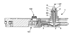
図2は、ディスプレー車セットが内側車セット6であり、中央パイプ2のメインボア4の内側でガイドされるような本発明の変形例を示している。ここで、軸方向の止め7は、内側車セット6の第1の支持面66に押し付けられた第1のリング71を有する付加された軸方向の止めである。これは、第1の支持面66の一端にて、内側車セット6に設けられた第1の肩部67上で支えられている。第1のリング71は、プレート3に対向するように、第1の止め面74を有する。これは、中央パイプ2の第1の上側面24に対する止めを形成するように構成している。内側車セット6は、プレート3に対して第1の支持面66の反対側に、第1の端面63を有する。これは、中央パイプ2の第1の下側面23とは反対側にある。具体的には、第1の上側面24及び/又は第1の下側面23は、主軸DPと垂直である。具体的には、第1の肩部67及び/又は第1の端面63は、主軸DPと垂直である。具体的には、第1の止め面74は、主軸DPと垂直である。
FIG. 2 shows a variant of the invention in which the display wheel set is the
このようにして、中央パイプ2に対する内側車セット6の相対的変位は、上側レベルでは第1の止め面74と第1の上側面24の間の当接係合によって、そして、この上側レベルとは反対側の下側レベルでは第1の端面63と第1の下側面23の間の当接係合によって、制限される。
In this way, the relative displacement of the
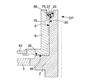
図5は、図2と類似しているが、ディスプレー車セットが外側車セット8であって中央パイプ2のメイン支持面5にガイドされるような、本発明の変形例を示している。軸方向の止め7は、中央パイプ2の第2の支持面29に押し付けられた第2のリング79を有する付加的な軸方向の止めであり、これは、第2の支持面29の一端において、中央パイプ2に設けられた第2の肩部27上で支えられている。この第2のリング79は、プレート3に対向するように、第2の止め面78を有する。これは、外側車セット8に設けられた第2の上側面88に対する止めを形成するように構成している。外側車セット8は、第2の上側面88の反対側、かつ、可能な限りプレート3の近くにおいて、第2の端面86を有する。これは、中央パイプ2の中間面26と対向している。このようにして、中央パイプ2に対する外側車セット8の相対的変位は、上側レベルでは第2の止め面78と第2の上側面88の間の当接係合によって、そして、プレート3と上側レベルの間に位置する中間レベルでは、第2の端面86と中間面26の間の当接係合によって、制限される。
FIG. 5 is similar to FIG. 2 but shows a variant of the invention in which the display wheel set is the
具体的には、内側車セット6は、中央秒車であり、この中央秒車のZ方向の軸方向の保持が、針側からアーバーに押し付けられたリングによって確実になる。
Specifically, the inner
分解が想定されないような変形例の1つにおいて、付加的なリングを、押し付けたり、接合したり、溶接したり、リベット付けしたり、圧着したり、これらに類似することをしたりすることができる。 In one variation where disassembly is not envisioned, the additional ring may be pressed, joined, welded, riveted, crimped, or the like it can.
図6及び7は、軸方向の止めが、中央パイプ2又は中央パイプ2によってガイドされる車セット上に、突出面を有するような第2の実施形態を示している。
FIGS. 6 and 7 show a second embodiment in which the axial stop has a protruding surface on the
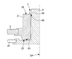
図6は、ディスプレー車セットが、中央パイプ2のメインボア4の内側でガイドされる内側車セット6でもあるような構成を示している。この場合においては、軸方向の止め7は、内側車セット6に設けられた第1の突出面69を有する。これは、プレート3と対向するように、第1の止め面68を有する。これは、中央パイプ2の第1の上側面24に対する止めを形成するように構成している。
FIG. 6 shows a configuration in which the display wheel set is also an
この突出面は、内側車セット6のアーバーを変形させることによって、材料を付加することによって、又は材料の除去によって作られる局部変形によって、実現することができる。これに制限されないが、内側車セット6のアーバーの材料を局所的に押し戻したり、突出部を形成したり、リベット用頭部を用いる折り曲げリップを用いてアーバーを前置機械加工したり、内側車セット6のアーバーを組み立てた後に、既に中央パイプ2の内側で挿入されており下側面に支えられている状況で、レーザー光線を用いて中央パイプ2の端面のすぐ上に周部クレーターを機械加工したり、止めを形成する1つのリップを有する単一の回転用切り込みを形成したり、プラズマ蒸着したり、1点のスポット又はいくつかのスポット又は線を溶接したり、同様なことをしたりすることができる。
This protruding surface can be realized by deforming the arbor of the
図2の変形例におけるように、内側車セット6は、プレート3に対して第1の支持面66とは反対側に、中央パイプ2の第1の下側面23に対向するように第1の端面63を有する。中央パイプ2に対する内側車セット6の相対的変位は、上側レベルでは第1の止め面68と第1の上側面24の間の当接係合によって、そして、上側レベルの反対側の下側レベルでは第1の端面63と第1の下側面23の間の当接係合によって、制限される。
As in the modification of FIG. 2, the
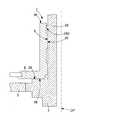
図7は、図6と類似しているが、ディスプレー車セットが外側車セット8でもあり、中央パイプ2のメイン支持面5にガイドされるような本発明の変形例を示している。軸方向の止め7は、中央パイプ2に設けられた第2の突出面28であり、これは、プレート3と対向するように、第2の止め面280を有し、これは、外側車セット8に設けられた第2の上側面88に対する止めを形成するように構成している。この第2の突出面28は、図6の第1の突出面69と同様な形態で実現することができる。外側車セット8は、第2の上側面88の反対側、かつ、可能な限りプレート3の近くにおいて、中央パイプ2の中間面26に対向するように第2の端面86を有する。このようにして、中央パイプ2に対する外側車セット8の相対的変位は、上側レベルでは第2の止め面280と第2の上側面88の間の当接係合によって、プレート3と上側レベルの間に位置している中間レベルでは第2の端面86と中間面26の間の当接係合によって、制限される。
FIG. 7 is similar to FIG. 6 but shows a variant of the invention in which the display wheel set is also the
図3及び4は、軸方向の止め7が少なくとも1つの中間的部品を有し、これが中央パイプ2と車セット6、8の間で捕獲されるようにマウントされており、中央パイプ2によってガイドされるような第3の実施形態を示している。
3 and 4, the
特に、本発明によると、この中間的部品は、保持リングなどのような弾性部品である。また、特に、軸方向の止め7は、中央パイプ2における外側溝21、22の内側と車セット6、8の内側溝61、82の内側の両方に収容される保持リング76、98を有する付加的な軸方向の止めである。
In particular, according to the present invention, this intermediate part is an elastic part such as a retaining ring. Also, in particular, the
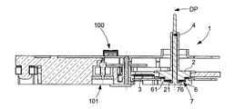
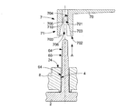
図3は、ディスプレー車セットが、中央パイプ2のメインボア4の内側でガイドされる内側車セット6であるような変形例を示している。ここで、付加的な軸方向の止めは、中央パイプ2の第1の外側溝21の内側と内側車セット6の第1の内側溝61の内側との両方に収容される第1の保持リング76である。中央パイプ2に対する内側車セット6の相対的変位は、第1の保持リング76と、第1の外側溝21の内側溝211及び212の第1の側面及び第1の内側溝61の外側溝611、612の第1の側面との間の当接係合によって制限される。
FIG. 3 shows a variant in which the display wheel set is an
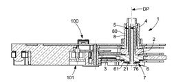
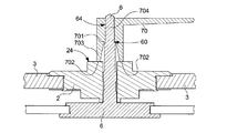
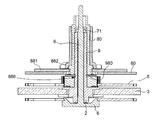
図4は、ディスプレー車セットが、中央パイプ2のメイン支持面5上でガイドされる外側車セット8であるような変形例を示している。ここで、付加的な軸方向の止め7は、中央パイプ2の第2の外側溝22の内側と外側車セット8の第2の内側溝82の内側の両方に収容される第2の保持リング98である。中央パイプ2に対する外側車セット8の相対的変位は、第2の保持リング98と、第2の外側溝22の内側溝221、222の第2の側面及び第2の内側溝82の外側溝821、822の第2の側面の間の当接係合によって制限されている。
FIG. 4 shows a variant in which the display wheel set is an
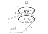
特に、内側車セット6は、中央秒車であり、この中央秒車のZ方向の軸方向の保持が、中央パイプにあらかじめマウントされた保持リングによって確実にされる。そして、下で説明する図11〜16に示すように、秒車が中央パイプ2に対してZ方向で可能な限り押し付けられると、この秒車はその内側溝を介して保持リングに嵌められる。
In particular, the
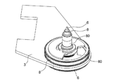
図8〜10に示すように、図2に示す内側車セット6のみについての第1の実施形態の特定の実施形態において、第1のリング71は、内側車セット6に嵌められる針70のパイプ710によって形成されており、これは、中央パイプ2の第1の上側端24上において、パイプ710に設けられたパイプ端面702を介して、安定配置される。特に、パイプ710は、端がパイプ端面702を形成している弾性リップ703を有し、これらは、パイプ710の内側フランジ701を、軸方向の止めの保持の正確な寸法を決める、内側車セット6のアーバーに設けられた周部溝60に嵌めることができるように構成している。
As shown in FIGS. 8 to 10, in a specific embodiment of the first embodiment only for the
別の変形例において、針71は、内側車セット6のアーバーの第1の支持面66に押し付けられ、第1の支持面66の一端において内側車セット6に設けられた第1の肩部67に当接する。特に、この内側車セット6は中央秒車セットである。この変形例において、中央パイプ2の第1の上側面24に対する止めを形成するのは、針のパイプ710である。このようにして、圧入寸法、そして、したがって、止めの位置を制御することができる。なぜなら、針が肩部に対して押し付けられるからである。
In another variant, the
図17〜23は、保持リングとしてはたらくプレートを備える3つの同心のギヤ列のアセンブリーを用いる別の変形例を示している。これによって、ケース裏側の棒体の必要性及び表盤側の棒体の必要性がなくなる。中央パイプ及びアーバーは、それらのプレートにリベット付けされるようにマウントされ、そして、垂直方向の挿入の際に、車セットが適切な位置に嵌められる。これらの車セットは、分離不能なアセンブリーを形成する。 FIGS. 17-23 show another variation using an assembly of three concentric gear trains with plates acting as retaining rings. This eliminates the need for a bar on the back side of the case and a bar on the front side. The central pipe and arbor are mounted to be riveted to their plates and the car set is fitted in place during vertical insertion. These vehicle sets form an inseparable assembly.
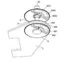
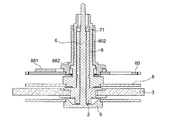
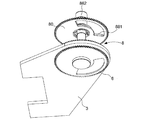
より正確には、図18、19及び20に示すように、内側車セット6は、特に、秒アーバーを担持し、印付き開口603を有する車を有し、また、この印付き開口603は、可撓性舌体601を担持するアーム602の境界を定め、この可撓性舌体601は、中央パイプ2に設けられた下側溝206と嵌め合い係合して、軸方向の止めとしてはたらくように構成している。
More precisely, as shown in FIGS. 18, 19 and 20, the
図18、20及び21に示すように、外側車セット8、特に、分車は、同様な構成を有し、印付き開口803が設けられた車を有し、また、この印付き開口803は、可撓性舌体801を担持するアーム802の境界を定め、この可撓性舌体801は、中央パイプ2に設けられた中央溝208と嵌め合い係合して、軸方向の止めとしてはたらくように構成している。
As shown in FIGS. 18, 20, and 21, the
図18、22及び23に示すように、上側車セット80、特に、時間車は、図2及び3と同様な形態で、同様な構成を有し、印付き開口8003が設けられた車を有し、また、この印付き開口8003は、可撓性舌体8001を担持するアーム8002の境界を定めており、この可撓性舌体8001は、外側車セット8に設けられた上側溝8000と嵌め合い係合して、軸方向の止めとしてはたらくように構成している。
As shown in FIGS. 18, 22 and 23, the upper wheel set 80, particularly the hour wheel, has the same configuration as that of FIGS. 2 and 3, and has a car with a
図17〜23は、3つの同心のギヤ列のアセンブリーを用いる別の変形例を示しており、これは、圧入された軸方向の止め71及び保持リングの両方を利用する軸方向の止めを用いる組み合わさった手法である。ここでも、裏蓋側の棒体及び表盤側の棒体を省くことができる。
FIGS. 17-23 illustrate another variation using an assembly of three concentric gear trains, which uses an axial stop that utilizes both a press-fit
より正確には、図24〜31に示した別の変形例において、図24〜26に示すように、内側車セット6のアーバー、特に、秒アーバーは、圧入された軸方向の止め71によって中央パイプ2の端にて止められる。
More precisely, in another variant shown in FIGS. 24 to 31, as shown in FIGS. 24 to 26, the arbor of the
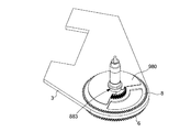
外側車セット8は、具体的には、分ピニオンを担持しており、この外側車セット8を保持リング980によって軸方向にブロックする2つの溝880を有し、この保持リング980の上において、外側車セット8が止め溝883を有する。
Specifically, the outer wheel set 8 carries a minute pinion, and has two
上側車セット80は、具体的には、図2及び3と同様な形態で筒かなを支えており、印付き開口がある車を有し、上側車セット80上で既にあらかじめ組み立てられている大きな保持リング881を有し、この保持リング881の最大直径は、上側車セット80の最大直径よりもわずかに小さく、この保持リング881は、筒かな882の肩部によって止められ、そして、上側車セット80は、軸方向の挿入の際に、止め溝883内の適切な位置に嵌められる。
Specifically, the upper car set 80 supports a cylindrical pinion in the same form as in FIGS. 2 and 3, has a car with a marked opening, and is a large part that is already assembled on the upper car set 80. Having a retaining
保持リング881には、さらに、切り欠きがある。これによって、最も近いボードにおける容量性開口(0.15mm)のレベルを上げることができる。この切り欠きは、時間車セットにおける釣り合いおもりを抑えることができ、したがって、最適化された非平衡があるように時間針をマウントすることができる。
The retaining
この改善を、針の非平衡のために、分車にも適用することができる。図28B及び28Cは、前記車の直径と非常に近い大きな直径のキー980を有する変形例を示しており、切り欠きの角度方向は、マウントされているときに、前記車における切り欠きに対応している。
This improvement can also be applied to the minute wheel due to needle imbalance. FIGS. 28B and 28C show a variation with a
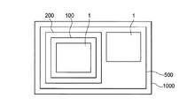
また、本発明は、計時器用モジュール100に関する。このモジュール100は、このモジュール100を計時器用ムーブメント500に固定するように構成するプレート2を有するモーターモジュールであり、これは、少なくとも1つのディスプレー車セット6、8を駆動するように構成するモーター手段101を有する。本発明によると、このモジュール100は、前記のようなディスプレー機構1を有する。
The present invention also relates to a
特に、モジュール100は、腕時計用のモーターモジュールに関連する同じ出願人による欧州特許出願EP15201458.5に開示されている特徴を有する。
In particular, the
本発明は、複数のモーターモジュールを有するモーター群200に関し、各モーターモジュールは、そのモジュールを計時器用ムーブメント500に固定するように構成しているプレート3を有する。好ましくは、これらのモーターモジュールのそれぞれは、少なくとも1つのディスプレー車セット6、8を駆動するように構成しているモーター手段101を有する。変形例の1つにおいて、モーター群200は、単にモーターモジュールを有するだけではなく、モーター手段がなく単に中間ギヤ列を有する少なくとも1つの中間的車モジュールをも有する。本発明によると、モーター群200を形成するモーターモジュールの少なくとも1つは、ディスプレー機構1を有する1つのこのようなモジュール100であり、そのプレート3が、モジュール100を計時器用ムーブメント500に固定するように構成している。前記のようなモーター群200が自立的であって、別のプレートに取り付けられることを必要としないことは明らかである。エネルギー格納手段、制御及び駆動手段によって支援されて、前記のようなムーブメント500を形成することができる。また、このモーター群200を腕時計ケース100内で直接固定することができる。
The present invention relates to a
変形例の1つにおいて、モーター群200は、複数のモジュール100を有し、各モジュール100は、前記のようなディスプレー車セット6、8を少なくとも1つ駆動するように構成している。
In one modification, the
このように、具体的には、モジュール100は、パワー及び制御手段を有する腕時計用のモジュールである。
Thus, specifically, the
特に、モジュール100は、中央秒アーバーのための棒体のないモーターモジュールである。
In particular, the
特に、モーター群200は、パワー及び制御手段を有する腕時計用のモーター群である。
In particular, the
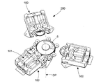
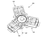
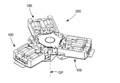
図11〜16は、Y字形(120°ごとに枝部がある三角状の星形)に組み立てられた3つのモーターモジュール100を有する前記のようなモーター群200を示しており、各モーターモジュール100は、少なくとも1つのディスプレー車セットを駆動するように構成しているモーター手段101を有する。
FIGS. 11 to 16 show such a
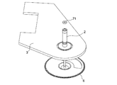
特定の組み立て手順によると、このモーター群200は、自身のプレート3上であらかじめ組み立てられた3つのモジュールによって形成されており、図11において中央パイプ2、中央パイプ2の外側溝21において示されている保持リング76を受け、嵌められ、中央パイプ2の内側に内側車セット6が挿入され、そして、図16における保持リング76上に内側車セット6が嵌められる。
According to a specific assembly procedure, this
したがって、中央秒モーターだけの場合には、棒体を有する必要はない。 Therefore, in the case of only the central second motor, it is not necessary to have a rod.
本発明は、さらに、少なくとも1つの前記のようなモーター群200及び/又は1つの前記のようなモジュール100及び/又は1つの前記のようなディスプレー機構1を有する計時器用ムーブメント500に関する。
The invention further relates to a
本発明は、さらに、前記のようなムーブメント500を少なくとも1つ及び/又は前記のようなディスプレー機構1を少なくとも1つ有する腕時計1000に関する。
The invention further relates to a
本発明には、以下のような著しい利点がある。
− 単一の車の回転を確実にするために棒体を備えないこと。
− 単一の部品によって回転を確実にして、ジュエルが中央パイプと整列していないときに、アーバーが捕獲されるリスクをなくしたこと。
− 秒車上の振動を減らし、二次元的な許容列があり、Z方向の安全高さを減らすことができること。
The present invention has the following significant advantages.
-Do not have rods to ensure the rotation of a single car.
-Ensured rotation by a single part, eliminating the risk of arbor being captured when the jewel is not aligned with the central pipe.
-Reduce the vibration on the second wheel, have a two-dimensional tolerance row, and reduce the safety height in the Z direction.
本発明は、電気機械式腕時計又は電子腕時計、特に、接続機能付き腕時計、の製造に特に良好に適合するものである。 The invention is particularly well suited for the manufacture of electromechanical watches or electronic watches, in particular watches with a connection function.
1 ディスプレー機構
2 中央パイプ
3 プレート
4 メインボア
5 メイン支持面
6 内側車セット
7 軸方向の止め
8 外側車セット
21 第1の外側溝
22 第2の外側溝
28、69 突出面
61 第1の内側溝
76 第1の保持リング
82 第2の内側溝
98 第2の保持リング
100 計時器用モジュール
101 モーター手段
200 モーター群
500 計時器用ムーブメント
1000 腕時計
211、212 内側溝
611、612、821、822 の外側溝
71、79、76、98 軸方向の止め
DP 主軸
DESCRIPTION OF
Claims (7)
前記中央パイプ(2)は、前記中央パイプ(2)の内側又は外側のディスプレー車セット(6、8)を受けて主軸(DP)のまわりに回転するようにガイドするような、少なくとも1つのメインボア(4)及び/又は1つのガイド用メイン支持面(5)を有し、
前記ディスプレー機構(1)は、前記中央パイプ(2)と前記ディスプレー車セット(6、8)の間の前記主軸(DP)の方向における軸方向の遊びを所定値までに制限するように構成している少なくとも1つの軸方向の止め(7)を有し、
前記少なくとも1つの軸方向の止め(7)は、前記中央パイプ(2)又は前記ディスプレー車セット(6、8)の突出面(28、69)、又は付加的な軸方向の止め(71、79、76、98)のいずれかであり、前記中央パイプ(2)と前記ディスプレー車セット(6、8)の間で捕獲されているようにマウントされており、又は前記ディスプレー車セット(6、8)に固定されており、
前記軸方向の止め(7)は、保持リング(76、98)を有する付加的な軸方向の止めであり、この保持リング(76、98)は、前記中央パイプ(2)に設けられた外側溝(21、22)の内側及び前記車セット(6、8)に設けられた内側溝(61、82)の内側の両方に収容される
ことを特徴とするディスプレー機構(1)。 A timer display mechanism (1) having a central pipe (2) fixed to a plate (3),
The central pipe (2) receives at least one display wheel set (6, 8) inside or outside the central pipe (2) and guides it to rotate around the main shaft (DP). (4) and / or one guide main support surface (5),
The display mechanism (1) is configured to limit axial play in the direction of the main shaft (DP) between the central pipe (2) and the display wheel set (6, 8) to a predetermined value. Having at least one axial stop (7),
The at least one axial stop (7) can be a protruding surface (28, 69) of the central pipe (2) or the display wheel set (6, 8) or an additional axial stop (71, 79). , 76, 98) mounted so as to be captured between the central pipe (2) and the display wheel set (6, 8), or the display wheel set (6, 8). )
The axial stop (7) is an additional axial stop with a retaining ring (76, 98), which is attached to the outer pipe provided on the central pipe (2). A display mechanism (1) characterized by being accommodated both inside the side grooves (21, 22) and inside the inner grooves (61, 82) provided in the wheel set (6, 8).
前記付加的な軸方向の止めは、前記中央パイプ(2)に設けられた第1の外側溝(21)の内側及び前記内側車セット(6)に設けられた第1の内側溝(61)の内側の両方に収容される第1の保持リング(76)であり、
前記中央パイプ(2)に対する前記内側車セット(6)の相対的変位は、前記第1の保持リング(76)と、前記第1の外側溝(21)の内側溝(211、212)の第1の側面及び前記第1の内側溝(61)の外側溝(611、612)の第1の外側面との間の当接係合によって制限される
ことを特徴とする請求項1に記載のディスプレー機構(1)。 The display wheel set (6, 8) is an inner wheel set (6) guided inside the main bore (4) of the central pipe (2),
The additional axial stop includes an inner side of a first outer groove (21) provided in the central pipe (2) and a first inner groove (61) provided in the inner wheel set (6). A first retaining ring (76) housed both inside the
The relative displacement of the inner wheel set (6) with respect to the central pipe (2) is the first displacement of the first retaining ring (76) and the inner grooves (211, 212) of the first outer groove (21). 2. Limited by abutting engagement between one side and the first outer surface of the outer groove (611, 612) of the first inner groove (61). Display mechanism (1).
前記付加的な軸方向の止め(7)は、前記中央パイプ(2)に設けられた第2の外側溝(22)の内側及び前記外側車セット(8)に設けられた第2の内側溝(82)の内側の両方に収容される第2の保持リング(98)であり、
前記中央パイプ(2)に対する前記外側車セット(8)の相対的変位は、前記第2の保持リング(98)と、前記第2の外側溝(22)の内側溝(221、222)の第2の外側面及び前記第2の内側溝(82)の外側溝(821、822)の第2の外側面との間の当接係合によって制限される
ことを特徴とする請求項1に記載のディスプレー機構(1)。 The display wheel set (6, 8) is an outer wheel set (8) guided on the main support surface (5) of the central pipe (2),
The additional axial stop (7) includes an inner second groove (22) provided in the central pipe (2) and a second inner groove provided in the outer wheel set (8). A second retaining ring (98) housed both inside (82);
The relative displacement of the outer wheel set (8) relative to the central pipe (2) is the second displacement of the second retaining ring (98) and the inner grooves (221, 222) of the second outer groove (22). 2. Limited by abutment engagement between the outer surface of the second and the second outer surface of the outer groove (821, 822) of the second inner groove (82). Display mechanism (1).
当該モジュール(100)を計時器用ムーブメント(500)に固定するように構成しているプレート(3)を有するモーターモジュールであり、
少なくとも1つのディスプレー車セット(6、8)を駆動するように構成しているモーター手段(101)を有し、
請求項1に記載のディスプレー機構(1)を有する
ことを特徴とする計時器用モジュール(100)。 A timer module (100) comprising:
A motor module having a plate (3) configured to secure the module (100) to a timer movement (500);
Motor means (101) configured to drive at least one display wheel set (6, 8);
A timer module (100) comprising the display mechanism (1) according to claim 1.
各モーターモジュールは、そのモジュール(100)を計時器用ムーブメント(500)に固定するように構成しているプレート(3)を有し、
各モーターモジュール(100)は、少なくとも1つのディスプレー車セット(6、8)を駆動するように構成しているモーター手段(101)を有し、
前記モーターモジュール(100)の少なくとも1つは、請求項4に記載のモーターモジュール(100)である
ことを特徴とするモーター群(200)。 A wristwatch motor group (200) having a plurality of motor modules,
Each motor module has a plate (3) configured to secure the module (100) to the timer movement (500);
Each motor module (100) has motor means (101) configured to drive at least one display wheel set (6, 8);
The motor group (200), wherein at least one of the motor modules (100) is the motor module (100) according to claim 4.
ことを特徴とする計時器用ムーブメント(500)。 A timepiece movement (500) comprising at least one display mechanism (1) according to claim 1.
ことを特徴とする腕時計(1000)。 A watch (1000) comprising at least one display mechanism (1) according to claim 1.
Applications Claiming Priority (3)
| Application Number | Priority Date | Filing Date | Title |
|---|---|---|---|
| EP15201458.5A EP3185089B1 (en) | 2015-12-21 | 2015-12-21 | Motor module for a watch |
| EP16164991.8 | 2016-04-13 | ||
| EP16164991.8A EP3185084B1 (en) | 2015-12-21 | 2016-04-13 | Display mechanism for a watch |
Publications (2)
| Publication Number | Publication Date |
|---|---|
| JP2017191101A true JP2017191101A (en) | 2017-10-19 |
| JP6313879B2 JP6313879B2 (en) | 2018-04-18 |
Family
ID=54850496
Family Applications (3)
| Application Number | Title | Priority Date | Filing Date |
|---|---|---|---|
| JP2016236793A Active JP6396973B2 (en) | 2015-12-21 | 2016-12-06 | Clock motor module |
| JP2017074974A Active JP6340106B2 (en) | 2015-12-21 | 2017-04-05 | Motor group for watches |
| JP2017074976A Active JP6313879B2 (en) | 2015-12-21 | 2017-04-05 | Display mechanism for watches |
Family Applications Before (2)
| Application Number | Title | Priority Date | Filing Date |
|---|---|---|---|
| JP2016236793A Active JP6396973B2 (en) | 2015-12-21 | 2016-12-06 | Clock motor module |
| JP2017074974A Active JP6340106B2 (en) | 2015-12-21 | 2017-04-05 | Motor group for watches |
Country Status (7)
| Country | Link |
|---|---|
| US (4) | US10228658B2 (en) |
| EP (3) | EP3185089B1 (en) |
| JP (3) | JP6396973B2 (en) |
| KR (2) | KR101960142B1 (en) |
| CN (4) | CN206946207U (en) |
| RU (1) | RU2725511C2 (en) |
| TW (2) | TWI721050B (en) |
Families Citing this family (10)
| Publication number | Priority date | Publication date | Assignee | Title |
|---|---|---|---|---|
| EP3185089B1 (en) * | 2015-12-21 | 2019-03-06 | ETA SA Manufacture Horlogère Suisse | Motor module for a watch |
| EP3495897B1 (en) * | 2017-12-08 | 2020-08-12 | ETA SA Manufacture Horlogère Suisse | Timepiece comprising an electric motor secured to an attachment plate |
| EP3537595A1 (en) * | 2018-03-09 | 2019-09-11 | ETA SA Manufacture Horlogère Suisse | Long-stroke linear piezoelectric motor |
| KR102110034B1 (en) * | 2018-05-21 | 2020-05-12 | 이세현 | Module-Type Wristwatch |
| EP3667435B1 (en) | 2018-12-10 | 2022-06-01 | Montres Breguet S.A. | System for adjusting the position of a first toothed moving part relative to a support on which the first toothed moving part is pivotably mounted, and timepiece comprising such a system |
| EP3822494A1 (en) * | 2019-11-13 | 2021-05-19 | ETA SA Manufacture Horlogère Suisse | Member and device for attaching a disc |
| CH716957A2 (en) * | 2019-12-16 | 2021-06-30 | Eta Sa Mft Horlogere Suisse | Guidance device for clock display. |
| WO2021239229A1 (en) * | 2020-05-28 | 2021-12-02 | Soprod S.A. | Analogue display module for watches |
| FI3923086T3 (en) * | 2020-06-12 | 2026-03-03 | Eta Sa Mft Horlogere Suisse | Motor module for a clock movement |
| CN114545756B (en) * | 2022-02-23 | 2024-08-16 | 东阳市华佳电子有限公司 | Positioning structure for clamping ring of dual-calendar movement |
Citations (2)
| Publication number | Priority date | Publication date | Assignee | Title |
|---|---|---|---|---|
| US20020141292A1 (en) * | 2001-04-03 | 2002-10-03 | Eta Sa Fabriques D'ebauches | Timepiece movement |
| US20130044574A1 (en) * | 2011-08-17 | 2013-02-21 | Eta Sa Manufacture Horlogere Suisse | Pre-adjustment of timepiece wheel set shake |
Family Cites Families (39)
| Publication number | Priority date | Publication date | Assignee | Title |
|---|---|---|---|---|
| US900380A (en) * | 1908-02-26 | 1908-10-06 | William Frederick Jost | Cannon-pinion. |
| JPS5086570U (en) * | 1973-12-10 | 1975-07-23 | ||
| JPS51137459A (en) * | 1975-05-23 | 1976-11-27 | Seikosha Co Ltd | Timepiece |
| US4233680A (en) * | 1978-05-03 | 1980-11-11 | Vdo Adolf Schindling Ag | Electric clock |
| CH638365B (en) * | 1981-02-26 | Ebauches Electroniques Sa | WATCH PART WITH RELEASE MECHANISM. | |
| DE8136793U1 (en) * | 1981-12-17 | 1983-02-24 | Gebrüder Junghans GmbH, 7230 Schramberg | Clockwork with a printed circuit board for an electronic drive control circuit and a carrier plate for the wheels and hands between two housing shells |
| CH653846GA3 (en) * | 1983-12-06 | 1986-01-31 | ||
| US4785434A (en) * | 1986-11-19 | 1988-11-15 | Casio Computer Co., Ltd. | Slip structure of a timepiece |
| US5172349A (en) * | 1989-04-21 | 1992-12-15 | Eta Sa Fabriques D'ebauches | Electronic timepiece with analog display |
| EP0393605B1 (en) * | 1989-04-21 | 1992-07-08 | Eta SA Fabriques d'Ebauches | Electronic time piece with at least two motors |
| US5331608A (en) * | 1992-03-31 | 1994-07-19 | Citizen Watch Co., Ltd. | Electronic watch with an antenna for a receiving device |
| US5155712A (en) * | 1992-04-20 | 1992-10-13 | Timex Corporation | Wheel and pinion assembly with friction drive/slip coupling for a timepiece |
| EP0679970B1 (en) * | 1994-04-25 | 1998-06-17 | Detra Sa | Multiphase-type stepping motor |
| FR2749949B1 (en) * | 1996-06-18 | 1998-08-07 | Ebauchesfabrik Eta Ag | WATCHMAKING MOVEMENT COMPRISING A GUIDE TUBE BETWEEN A PLATE AND A BRIDGE |
| FR2752496B1 (en) * | 1996-08-14 | 1998-10-23 | Ebauchesfabrik Eta Ag | ELECTROMECHANICAL TRANSDUCER HAVING TWO PERMANENT MAGNET ROTORS |
| JP3328518B2 (en) * | 1996-11-06 | 2002-09-24 | セイコークロック株式会社 | Clock mechanical body |
| JP2000275365A (en) * | 1999-03-23 | 2000-10-06 | Rhythm Watch Co Ltd | Driver of clock |
| WO2002013357A1 (en) * | 2000-08-03 | 2002-02-14 | Fdk Corporation | Stepping motor |
| DE60112036T2 (en) | 2001-04-03 | 2006-06-01 | Eta Sa Manufacture Horlogère Suisse | clockwork |
| CN100378604C (en) * | 2001-12-21 | 2008-04-02 | 北川工业株式会社 | Clock and wheel train device with substrate made of resin |
| US20050127782A1 (en) * | 2001-12-21 | 2005-06-16 | Morinobu Endo | Ultrasonic motor, and electronic timepiece having ultrasonic motor |
| US7057977B1 (en) * | 2003-01-15 | 2006-06-06 | Timex Group B.V. | Flexible bridge for a watch module |
| US8526272B2 (en) * | 2004-02-28 | 2013-09-03 | Dayclocks, Inc. | Day and time chronometer movement |
| JP4386022B2 (en) * | 2004-11-10 | 2009-12-16 | セイコーエプソン株式会社 | Clock display device, movement, and clock |
| CN200959565Y (en) * | 2006-07-24 | 2007-10-10 | 伟盈驱动技术有限公司 | stepper motor |
| JP4623140B2 (en) * | 2008-05-28 | 2011-02-02 | カシオ計算機株式会社 | Needle position detection device and needle position detection control method |
| US20100220559A1 (en) * | 2009-02-27 | 2010-09-02 | Galie Louis M | Electromechanical Module Configuration |
| RU2410740C1 (en) * | 2009-12-24 | 2011-01-27 | Юрий Григорьевич Киселёв | Kiselev's crystal clock (versions) |
| EP2605087B1 (en) * | 2011-12-13 | 2017-07-26 | ETA SA Manufacture Horlogère Suisse | Modular clock assembly with functional modules |
| EP2787399B1 (en) * | 2011-12-13 | 2015-07-29 | ETA SA Manufacture Horlogère Suisse | Modular clock movement with functional modules |
| EP2634649B1 (en) * | 2012-02-29 | 2017-07-12 | ETA SA Manufacture Horlogère Suisse | Inexpensive timepiece barrel |
| EP2823365B1 (en) | 2012-02-29 | 2016-04-20 | ETA SA Manufacture Horlogère Suisse | Hand adjustment under dial |
| CN104122786B (en) * | 2013-04-23 | 2017-05-03 | 林祥平 | Timekeeper |
| EP2813904B1 (en) | 2013-06-10 | 2020-03-25 | ETA SA Manufacture Horlogère Suisse | Electronic movement comprising a clock motor |
| EP2842586A1 (en) * | 2013-08-27 | 2015-03-04 | PharmaSens AG | Device with a lavet-type motor |
| JP5939222B2 (en) * | 2013-09-27 | 2016-06-22 | カシオ計算機株式会社 | Stepping motor and clock |
| EP3070538B1 (en) | 2015-03-18 | 2020-03-11 | Nogerah SA | Retrograde display mechanism for a clock movement |
| CH711297B1 (en) * | 2015-07-07 | 2021-04-30 | Soprod Sa | Watch module and electromechanical watch comprising such a watch module. |
| EP3185089B1 (en) * | 2015-12-21 | 2019-03-06 | ETA SA Manufacture Horlogère Suisse | Motor module for a watch |
-
2015
- 2015-12-21 EP EP15201458.5A patent/EP3185089B1/en active Active
-
2016
- 2016-04-13 EP EP17160287.3A patent/EP3223084B1/en active Active
- 2016-04-13 EP EP16164991.8A patent/EP3185084B1/en active Active
- 2016-11-21 US US15/357,172 patent/US10228658B2/en active Active
- 2016-11-29 TW TW105139268A patent/TWI721050B/en active
- 2016-12-06 JP JP2016236793A patent/JP6396973B2/en active Active
- 2016-12-20 CN CN201621404642.9U patent/CN206946207U/en active Active
- 2016-12-20 CN CN201611186677.4A patent/CN106909060B/en active Active
- 2016-12-20 KR KR1020160174870A patent/KR101960142B1/en active Active
-
2017
- 2017-03-20 TW TW106109207A patent/TWI763659B/en active
- 2017-03-22 US US15/466,046 patent/US10048650B2/en active Active
- 2017-03-24 US US15/468,663 patent/US10545460B2/en active Active
- 2017-04-05 JP JP2017074974A patent/JP6340106B2/en active Active
- 2017-04-05 JP JP2017074976A patent/JP6313879B2/en active Active
- 2017-04-11 KR KR1020170046594A patent/KR101946147B1/en active Active
- 2017-04-12 CN CN201710236175.6A patent/CN107290949B/en active Active
- 2017-04-12 RU RU2017112381A patent/RU2725511C2/en active
- 2017-04-12 CN CN201710235974.1A patent/CN107290948B/en active Active
-
2019
- 2019-10-03 US US16/592,469 patent/US12248280B2/en active Active
Patent Citations (4)
| Publication number | Priority date | Publication date | Assignee | Title |
|---|---|---|---|---|
| US20020141292A1 (en) * | 2001-04-03 | 2002-10-03 | Eta Sa Fabriques D'ebauches | Timepiece movement |
| JP2002357672A (en) * | 2001-04-03 | 2002-12-13 | Eta Sa Fab Ebauches | Timepiece movement |
| US20130044574A1 (en) * | 2011-08-17 | 2013-02-21 | Eta Sa Manufacture Horlogere Suisse | Pre-adjustment of timepiece wheel set shake |
| JP2013040942A (en) * | 2011-08-17 | 2013-02-28 | Eta Sa Manufacture Horlogere Suisse | Pre-adjustment of timepiece wheel set shake |
Also Published As
Similar Documents
| Publication | Publication Date | Title |
|---|---|---|
| JP6313879B2 (en) | Display mechanism for watches | |
| JP5551231B2 (en) | Modular watch movement with functional modules | |
| US8740452B2 (en) | Pre-adjustment of timepiece wheel set shake | |
| JP2014041155A (en) | Autonomous control mechanism for timepiece | |
| US4488819A (en) | Electronic watch movement with modular stepper motor and setting mechanism | |
| US8750079B2 (en) | Display device with a combination of display members | |
| US4084403A (en) | Driving mechanism for a timepiece | |
| US20230341817A1 (en) | Three-dimensional karussel- or tourbillon-type regulating member provided with a peripheral ball bearing | |
| CN116931409A (en) | Three-dimensional karhunen for timepiece movement | |
| HK1245423B (en) | Motor group for watches | |
| HK1244896B (en) | Display mechanism for watches | |
| JP2015187596A (en) | Gear train mechanism, movement, and timepiece | |
| JPS6153669B2 (en) | ||
| JPS6140947B2 (en) | ||
| JP2003279670A (en) | Timepiece | |
| HK40073011A (en) | Clockwork selector mechanism | |
| JP2007121078A (en) | Pointer clock and standard time radio wave reception type multi-needle clock | |
| HK1186532B (en) | Modular timepiece movement with functional modules | |
| HK1186532A (en) | Modular timepiece movement with functional modules | |
| JP2014006163A (en) | Gear body, train wheel mechanism, movement for timepiece and timepiece |
Legal Events
| Date | Code | Title | Description |
|---|---|---|---|
| A977 | Report on retrieval |
Free format text: JAPANESE INTERMEDIATE CODE: A971007 Effective date: 20180222 |
|
| TRDD | Decision of grant or rejection written | ||
| A01 | Written decision to grant a patent or to grant a registration (utility model) |
Free format text: JAPANESE INTERMEDIATE CODE: A01 Effective date: 20180313 |
|
| A61 | First payment of annual fees (during grant procedure) |
Free format text: JAPANESE INTERMEDIATE CODE: A61 Effective date: 20180323 |
|
| R150 | Certificate of patent or registration of utility model |
Ref document number: 6313879 Country of ref document: JP Free format text: JAPANESE INTERMEDIATE CODE: R150 |
|
| R250 | Receipt of annual fees |
Free format text: JAPANESE INTERMEDIATE CODE: R250 |
|
| R250 | Receipt of annual fees |
Free format text: JAPANESE INTERMEDIATE CODE: R250 |
|
| R250 | Receipt of annual fees |
Free format text: JAPANESE INTERMEDIATE CODE: R250 |
|
| R250 | Receipt of annual fees |
Free format text: JAPANESE INTERMEDIATE CODE: R250 |
|
| R250 | Receipt of annual fees |
Free format text: JAPANESE INTERMEDIATE CODE: R250 |