JP2017191121A - Eyepiece structure of surgical microscope - Google Patents
Eyepiece structure of surgical microscope Download PDFInfo
- Publication number
- JP2017191121A JP2017191121A JP2016078646A JP2016078646A JP2017191121A JP 2017191121 A JP2017191121 A JP 2017191121A JP 2016078646 A JP2016078646 A JP 2016078646A JP 2016078646 A JP2016078646 A JP 2016078646A JP 2017191121 A JP2017191121 A JP 2017191121A
- Authority
- JP
- Japan
- Prior art keywords
- cylinder
- inner cylinder
- eyepiece
- surgical microscope
- optical axis
- Prior art date
- Legal status (The legal status is an assumption and is not a legal conclusion. Google has not performed a legal analysis and makes no representation as to the accuracy of the status listed.)
- Pending
Links
Images





Classifications
-
- G—PHYSICS
- G02—OPTICS
- G02B—OPTICAL ELEMENTS, SYSTEMS OR APPARATUS
- G02B25/00—Eyepieces; Magnifying glasses
- G02B25/001—Eyepieces
-
- G—PHYSICS
- G02—OPTICS
- G02B—OPTICAL ELEMENTS, SYSTEMS OR APPARATUS
- G02B21/00—Microscopes
- G02B21/0004—Microscopes specially adapted for specific applications
- G02B21/0012—Surgical microscopes
-
- G—PHYSICS
- G02—OPTICS
- G02B—OPTICAL ELEMENTS, SYSTEMS OR APPARATUS
- G02B7/00—Mountings, adjusting means, or light-tight connections, for optical elements
- G02B7/02—Mountings, adjusting means, or light-tight connections, for optical elements for lenses
- G02B7/04—Mountings, adjusting means, or light-tight connections, for optical elements for lenses with mechanism for focusing or varying magnification
-
- G—PHYSICS
- G02—OPTICS
- G02B—OPTICAL ELEMENTS, SYSTEMS OR APPARATUS
- G02B21/00—Microscopes
- G02B21/18—Arrangements with more than one light path, e.g. for comparing two specimens
- G02B21/20—Binocular arrangements
Landscapes
- Physics & Mathematics (AREA)
- General Physics & Mathematics (AREA)
- Optics & Photonics (AREA)
- Health & Medical Sciences (AREA)
- General Health & Medical Sciences (AREA)
- Surgery (AREA)
- Chemical & Material Sciences (AREA)
- Analytical Chemistry (AREA)
- Viewfinders (AREA)
- Lens Barrels (AREA)
- Microscoopes, Condenser (AREA)
- Lenses (AREA)
Abstract
【課題】内筒を視度調整のために光軸方向に移動しても内筒自体は回転しない手術顕微鏡の接眼部構造を提供する。【解決手段】外筒6,7を回転させると外筒7の内面の螺旋溝19にガイドされて、内筒4の突起16が光軸方向へ進退動するが、その突起16が非回転の中間筒5のストレート孔17にガイドされているため、光軸方向に移動するが回転はしない。内筒4に乱視是正レンズ10を追加したため、乱視の術者もメガネを外して手術することができる。【選択図】 図6Provided is an eyepiece structure of a surgical microscope in which the inner cylinder itself does not rotate even when the inner cylinder is moved in the optical axis direction for diopter adjustment. When outer cylinders 6 and 7 are rotated, they are guided by a spiral groove 19 on the inner surface of the outer cylinder 7 and a projection 16 of the inner cylinder 4 moves forward and backward in the optical axis direction, but the projection 16 is not rotated. Since it is guided by the straight hole 17 of the intermediate cylinder 5, it moves in the optical axis direction but does not rotate. Since the astigmatism correcting lens 10 is added to the inner cylinder 4, an astigmatism operator can also operate with the glasses removed. [Selection] Figure 6
Description
本発明は手術顕微鏡の接眼部構造に関するものである。 The present invention relates to an eyepiece structure of a surgical microscope.
手術顕微鏡は術部を立体的に観察するために左右一対の接眼部を備えている。接眼部の内部には観察者の個人的な視力に対応して視度調整するための視度調整レンズが内蔵されている。 The surgical microscope includes a pair of left and right eyepieces for observing the surgical part in three dimensions. A diopter adjustment lens for adjusting diopter corresponding to the observer's personal visual acuity is built in the eyepiece.
視度調整レンズは接眼部の内筒に固定され、外筒を回転させることにより内筒ごと光軸方向に移動する。視度調整レンズは内筒と一緒に回転しながら移動するようになっている(例えば、特許文献1参照)。 The diopter adjustment lens is fixed to the inner cylinder of the eyepiece, and moves together with the inner cylinder in the optical axis direction by rotating the outer cylinder. The diopter adjustment lens moves while rotating together with the inner cylinder (for example, see Patent Document 1).
しかしながら、このような関連技術にあっては、接眼部の内部の視度調整レンズは回転方向で指向性がないため、内筒と一緒に回転しても問題ないが、回転方向で指向性のある補正レンズは視度調整レンズに付加できない。例えば、乱視の術者が乱視是正レンズを内筒側に付加し、手術中はメガネを外していたいという要請がある。乱視是正レンズは向きが決まっており回転すると機能が損なわれるため、接眼部には付加できないという課題があった。 However, in such a related technology, the diopter adjustment lens inside the eyepiece has no directivity in the rotation direction, so there is no problem even if it rotates together with the inner cylinder. A correction lens with a diameter cannot be added to a diopter adjustment lens. For example, there is a demand for an astigmatism operator to add an astigmatism correcting lens to the inner cylinder side and to remove glasses during the operation. The astigmatism correcting lens has a fixed orientation, and its function is impaired when it rotates, so there is a problem that it cannot be added to the eyepiece.
また一方で接眼部における内筒端末のラバーに左右方向外側へ突出したサイド部を形成したいという要請もある。これは横方向から接眼部内に外光が進入するのを防止するためである。この場合もサイド部の向きが決まっているため回転する内筒に取付けることができない。 On the other hand, there is also a demand for forming a side portion protruding outward in the left-right direction on the rubber of the inner tube terminal in the eyepiece. This is to prevent external light from entering the eyepiece from the lateral direction. Also in this case, since the direction of the side portion is determined, it cannot be attached to the rotating inner cylinder.
本発明によれば、このような関連技術に着目してなされたものであり、視度調整のために内筒が光軸方向に移動しても光軸を中心に回転しない手術顕微鏡の接眼部構造を提供することができる。 According to the present invention, an eyepiece of a surgical microscope that does not rotate around the optical axis even when the inner cylinder moves in the optical axis direction for diopter adjustment is made by paying attention to such related technology. A partial structure can be provided.
本発明の第1の側面は、視度調整レンズを内蔵した内筒と、回転操作される外筒を備えた手術顕微鏡の接眼部構造であって、外筒と内筒との間に非回転の中間筒を設け、該中間筒にストレート孔を形成し、外筒の内面には螺旋溝を形成し、内筒の外面に形成した突起をストレート孔を介して螺旋溝に係合させたことを特徴とする。 A first aspect of the present invention is an eyepiece structure of a surgical microscope provided with an inner cylinder incorporating a diopter adjustment lens and a rotating outer cylinder. An intermediate cylinder for rotation was provided, a straight hole was formed in the intermediate cylinder, a spiral groove was formed on the inner surface of the outer cylinder, and a protrusion formed on the outer surface of the inner cylinder was engaged with the spiral groove through the straight hole It is characterized by that.
本発明の第2の側面は、内筒に乱視是正レンズを追加したことを特徴とする。 According to a second aspect of the present invention, an astigmatism correcting lens is added to the inner cylinder.
本発明の第3の側面は、内筒の端末に左右方向外側へ突出するサイド部を有するラバーを取付けたことを特徴とする。 The third aspect of the present invention is characterized in that a rubber having a side portion protruding outward in the left-right direction is attached to the terminal of the inner cylinder.
本発明の第4の側面は、中間筒の基端側に外筒の表面よりも大径のフランジを形成したことを特徴とする。 The fourth aspect of the present invention is characterized in that a flange having a larger diameter than the surface of the outer cylinder is formed on the base end side of the intermediate cylinder.
本発明の第1の側面によれば、外筒を回転させると外筒の内面の螺旋溝にガイドされて、内筒の突起が光軸方向へ進退動するが、その突起が非回転の中間筒のストレート孔にガイドされているため、内筒は光軸方向へ直線状に移動するが光軸を中心に回転はしない。 According to the first aspect of the present invention, when the outer cylinder is rotated, it is guided by the spiral groove on the inner surface of the outer cylinder, and the protrusion of the inner cylinder moves back and forth in the optical axis direction. Since it is guided by the straight hole of the cylinder, the inner cylinder moves linearly in the direction of the optical axis, but does not rotate around the optical axis.
本発明の第2の側面によれば、内筒に乱視是正レンズを追加したため、乱視の術者もメガネを外して手術することができる。また乱視是正レンズが回転しないためその乱視是正機能は維持される。 According to the second aspect of the present invention, since an astigmatism correcting lens is added to the inner cylinder, an astigmatism operator can also operate with the glasses removed. Since the astigmatism correcting lens does not rotate, the astigmatism correcting function is maintained.
本発明の第3の側面によれば、内筒の端末にサイド部を有するラバーを取付けたため、視度調整のために内筒を進退動させてもサイド部の位置は不変で、横方向からの外光の侵入を確実に防止することができる。 According to the third aspect of the present invention, since the rubber having the side portion is attached to the terminal of the inner cylinder, even if the inner cylinder is moved forward and backward for diopter adjustment, the position of the side portion does not change, and from the lateral direction. Intrusion of outside light can be reliably prevented.
本発明の第4の側面によれば、中間筒の基端側に外筒の表面よりも大径のフランジを形成したため、接眼部を覆うドレープのシール部分がこのフランジに引っかかり、ドレープが接眼部の基端側へずれて接眼部が露出するおそれがない。 According to the fourth aspect of the present invention, since the flange having a diameter larger than the surface of the outer cylinder is formed on the base end side of the intermediate cylinder, the seal portion of the drape covering the eyepiece is caught by this flange, and the drape is in contact with the flange. There is no possibility that the eyepiece part is exposed by shifting to the proximal end side of the eye part.
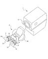
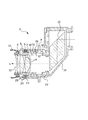
図1〜図11は本発明の好適な実施形態を示す図である。 1 to 11 are views showing a preferred embodiment of the present invention.
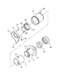
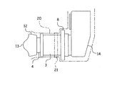
手術顕微鏡1の光束取出口11には接眼光学部2が取付けられている。接眼光学部2は2つの接眼部3を有している。接眼部3は内筒4と中間筒5と外筒6、7から構成されている。外筒6、7は2部品から形成されている。中間筒5の基端側には外筒6の表面より外側へ突出する大径のフランジ8が形成されている。
An eyepiece
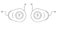
内筒4には視度調整レンズ9が内蔵されている。また視度調整レンズ9の手前には乱視是正レンズ10も付加されている。内筒4の先端にはラバー12が取付けられている。このラバー12は外光の侵入を防止するためのものである。ラバー12には左右方向外側に突出したサイド部13が一体的に形成されている。これは特に横からの外光の侵入を防止するためのものである。
A
接眼光学部2のリンク部14にはプリズム15が内蔵され、光束取出口11から取り出された左右一対の光束Lがプリズム15を経て接眼部3により術者の瞳に導かれる。
A
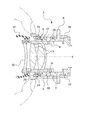
内筒4の外面には突起16が取付けられている。中間筒5には光軸K(図6参照)に沿うストレート孔17が形成されている。中間筒5はカラー18、22を介してリンク部14へ固定され非回転状態となっている。外筒6、7は内面側の部品に螺旋溝19が形成されている。内筒4の突起16は中間筒5のストレート孔17を介して外筒7の螺旋溝19に係合されている。23はストッパリングで、中間筒5に被せた状態で中間筒5のネジに螺合され、一部に形成されたスリット24をスクリュー25で締めてスリット24を狭めることにより中間筒5のネジに固定され、外筒7の抜けを防止するためものもである。外筒7に対しては外筒6がピン26で固定されるため、外筒6の抜けも防止される。
A
視度調整のために内筒4を進退動させる場合には、外筒6を手で持って回転させる。すると螺旋溝19が突起16に対して相対的に回転するため、回転方向に応じて突起16を前後に押し、内筒4を光軸Kに沿って直線的に進退動させる。この時は突起16が非回転の中間筒5のストレート孔17内にガイドされているため、内筒4は進退動しても回転することはない。
When the
従って乱視是正レンズ10の指向性は保たれるため、術者に対する乱視防止機能を十分に発揮することができる。術者はメガネを外した状態で手術することができ、手術の効率を高めることができる。
Therefore, since the directivity of the
また内筒4が回転しないため、内筒4の先端のラバー12に形成されたサイド部13も回転せず、横方向からの外光の侵入を確実に防止することができる。
Further, since the
更に、中間筒5の基端には外筒6の表面より大径のフランジ8が形成されているため、接眼部3を滅菌ドレープ20で覆った場合、ドレープ20の拘束テープ21がこのフランジ8に引っかかり、ドレープ20が接眼部3の基端側にずれて接眼部3が露出することを防止することができる。
Further, since the
以下、この発明の変形例を説明する。 Hereinafter, modifications of the present invention will be described.
外筒6、7を2部品で構成したが1部品で形成しても良い。
Although the
視度調整レンズ9に付加するレンズは乱視是正レンズ10に限定されず、回転方向で指向性を有するその他の補正レンズでも良い。
The lens added to the
1 手術顕微鏡
3 接眼部
4 内筒
5 中間筒
6、7 外筒
8 フランジ
9 視度調整レンズ
10 乱視是正レンズ
11 光束取出口
12 ラバー
13 サイド部
16 突起
17 ストレート孔
19 螺旋溝
L 光束
K 光軸
DESCRIPTION OF
Claims (4)
外筒と内筒との間に非回転の中間筒を設け、該中間筒にストレート孔を形成し、
外筒の内面には螺旋溝を形成し、
内筒の外面に形成した突起をストレート孔を介して螺旋溝に係合させたことを特徴とする手術顕微鏡の接眼部構造。 An eyepiece structure of a surgical microscope having an inner cylinder containing a diopter adjustment lens and an outer cylinder to be rotated,
A non-rotating intermediate cylinder is provided between the outer cylinder and the inner cylinder, a straight hole is formed in the intermediate cylinder,
A spiral groove is formed on the inner surface of the outer cylinder,
An eyepiece structure of a surgical microscope, wherein a projection formed on the outer surface of the inner cylinder is engaged with a spiral groove through a straight hole.
The eyepiece structure of a surgical microscope according to any one of claims 1 to 3, wherein a flange having a diameter larger than the surface of the outer cylinder is formed on the proximal end side of the intermediate cylinder.
Priority Applications (2)
| Application Number | Priority Date | Filing Date | Title |
|---|---|---|---|
| JP2016078646A JP2017191121A (en) | 2016-04-11 | 2016-04-11 | Eyepiece structure of surgical microscope |
| US15/468,840 US20170293135A1 (en) | 2016-04-11 | 2017-03-24 | Eyepiece structure for surgical microscope |
Applications Claiming Priority (1)
| Application Number | Priority Date | Filing Date | Title |
|---|---|---|---|
| JP2016078646A JP2017191121A (en) | 2016-04-11 | 2016-04-11 | Eyepiece structure of surgical microscope |
Publications (1)
| Publication Number | Publication Date |
|---|---|
| JP2017191121A true JP2017191121A (en) | 2017-10-19 |
Family
ID=59998068
Family Applications (1)
| Application Number | Title | Priority Date | Filing Date |
|---|---|---|---|
| JP2016078646A Pending JP2017191121A (en) | 2016-04-11 | 2016-04-11 | Eyepiece structure of surgical microscope |
Country Status (2)
| Country | Link |
|---|---|
| US (1) | US20170293135A1 (en) |
| JP (1) | JP2017191121A (en) |
Families Citing this family (1)
| Publication number | Priority date | Publication date | Assignee | Title |
|---|---|---|---|---|
| CN113671686A (en) * | 2021-07-16 | 2021-11-19 | 河北汉光重工有限责任公司 | Infrared sighting telescope lightweight diopter adjustable eyepiece |
Family Cites Families (18)
| Publication number | Priority date | Publication date | Assignee | Title |
|---|---|---|---|---|
| US2155389A (en) * | 1937-03-09 | 1939-04-25 | Ultrad Products Inc | Sighting means for guns |
| US2945415A (en) * | 1955-12-06 | 1960-07-19 | Ednalite Optical Company Inc | View finder for zoom lens |
| US3951522A (en) * | 1972-05-15 | 1976-04-20 | Canon Kabushiki Kaisha | Lens structure having a movable portion |
| US4595265A (en) * | 1983-04-04 | 1986-06-17 | Hodgson R W | Portable field inspection microscope for inspecting a butt end of a cylindrical object, such as a fiber optics cable |
| US5121251A (en) * | 1989-04-25 | 1992-06-09 | Edwards Optical Corporation | Telemicroscope with absorbing annular baffle |
| US5225932A (en) * | 1992-07-02 | 1993-07-06 | Litton Systems, Inc. | Eyecup insert for night vision goggles |
| WO1996020389A1 (en) * | 1994-12-28 | 1996-07-04 | Keymed (Medical & Industrial Equipment) Ltd. | Digitally measuring scopes using a high resolution encoder |
| US5764410A (en) * | 1996-06-05 | 1998-06-09 | Hakko Co., Ltd. | Telescope including an interposition gear for zoom operation |
| US5835289A (en) * | 1997-01-07 | 1998-11-10 | Berry; James M. | Auxiliary lens attachment for an optical device |
| DE10027167B4 (en) * | 1999-05-31 | 2007-03-22 | Pentax Corp. | Microscope with a lighting system |
| JP2001241892A (en) * | 2000-02-25 | 2001-09-07 | Hakko Shoji:Kk | Sighting telescope |
| US6480339B2 (en) * | 2001-02-05 | 2002-11-12 | Larry W. Clark | Corrective lens for rifle scope |
| US6667836B2 (en) * | 2001-04-19 | 2003-12-23 | Panavision, Inc. | High performance viewfinder eyepiece with a large diopter focus range |
| JP4703992B2 (en) * | 2004-09-02 | 2011-06-15 | Hoya株式会社 | Zoom lens barrel cam mechanism |
| EP2848977B1 (en) * | 2005-01-26 | 2018-02-28 | Leupold & Stevens, Inc. | Scope with improved magnification system |
| JP5414417B2 (en) * | 2009-08-07 | 2014-02-12 | キヤノン株式会社 | Zoom lens barrel |
| DE102013110425A1 (en) * | 2013-09-20 | 2015-04-09 | Karl Storz Gmbh & Co. Kg | eyepiece |
| CN104678532B (en) * | 2013-12-03 | 2017-08-08 | 博立码杰通讯(深圳)有限公司 | Zoom focusing mechanism and zoom lens |
-
2016
- 2016-04-11 JP JP2016078646A patent/JP2017191121A/en active Pending
-
2017
- 2017-03-24 US US15/468,840 patent/US20170293135A1/en not_active Abandoned
Also Published As
| Publication number | Publication date |
|---|---|
| US20170293135A1 (en) | 2017-10-12 |
Similar Documents
| Publication | Publication Date | Title |
|---|---|---|
| US7990610B2 (en) | Stereomicroscope with repositioning assistant's microscope | |
| JP6319860B2 (en) | Binocular loupe | |
| US8556427B2 (en) | Operating microscope system | |
| US8437078B2 (en) | Binoculars | |
| JP6418578B2 (en) | Stereoscopic rigid endoscope | |
| JP6141558B1 (en) | Endoscope hood for endoscope | |
| JP4974537B2 (en) | Focus adjustment device and optical apparatus | |
| US20170293135A1 (en) | Eyepiece structure for surgical microscope | |
| JP2010049111A (en) | Eyecup for eyepiece | |
| US8194314B2 (en) | Binoculars | |
| JP5016256B2 (en) | Binocular magnifier | |
| JP4925678B2 (en) | Optical device with eye width adjustment function | |
| JP2001133690A (en) | Microscope for surgery | |
| JP2017055296A (en) | Wearable imaging apparatus | |
| JPH08160494A (en) | Aim of optical equipment | |
| JP5580955B1 (en) | Endoscopic eyepiece device and endoscope | |
| JP2009244293A (en) | Magnification-variable optical equipment | |
| JP4704207B2 (en) | Diopter correction finder aids | |
| JP2008170712A (en) | binoculars | |
| JP6274586B2 (en) | Binocular loupe | |
| JPH0868947A (en) | Optical device with diopter ring | |
| CN121264952A (en) | Stereoscopic vision optimizing device for ophthalmic operation microscope | |
| JP2017130829A (en) | Unsterilized camera | |
| JP2004252020A (en) | Telescope, lens hood for telescope and aiming device for telescope | |
| JP2018205371A (en) | Eyepiece structure of surgical microscope |
Legal Events
| Date | Code | Title | Description |
|---|---|---|---|
| A621 | Written request for application examination |
Free format text: JAPANESE INTERMEDIATE CODE: A621 Effective date: 20190201 |
|
| A977 | Report on retrieval |
Free format text: JAPANESE INTERMEDIATE CODE: A971007 Effective date: 20190918 |
|
| A131 | Notification of reasons for refusal |
Free format text: JAPANESE INTERMEDIATE CODE: A131 Effective date: 20191029 |
|
| A02 | Decision of refusal |
Free format text: JAPANESE INTERMEDIATE CODE: A02 Effective date: 20200526 |