JP2017191182A - Powder replenishing apparatus and image forming apparatus - Google Patents

Powder replenishing apparatus and image forming apparatus Download PDF

Info

Publication number
JP2017191182A
JP2017191182A JP2016079711A JP2016079711A JP2017191182A JP 2017191182 A JP2017191182 A JP 2017191182A JP 2016079711 A JP2016079711 A JP 2016079711A JP 2016079711 A JP2016079711 A JP 2016079711A JP 2017191182 A JP2017191182 A JP 2017191182A
Authority
JP
Japan
Prior art keywords
powder
toner
container
amount
replenishing
Prior art date
Legal status (The legal status is an assumption and is not a legal conclusion. Google has not performed a legal analysis and makes no representation as to the accuracy of the status listed.)
Pending
Application number
JP2016079711A
Other languages
Japanese (ja)
Inventor
嘉子 小川
Yoshiko Ogawa
嘉子 小川
松本 純一
Junichi Matsumoto
純一 松本
健雄 関
Takeo Seki
健雄 関
英毅 吉水
Hideki Yoshimizu
英毅 吉水
廣田 哲郎
Tetsuo Hirota
哲郎 廣田
山田 正明
Masaaki Yamada
山田  正明
善行 福田
Yoshiyuki Fukuda
善行 福田
裕司 石倉
Yuji Ishikura
裕司 石倉
啓 齋藤
Akira Saito
啓 齋藤
Current Assignee (The listed assignees may be inaccurate. Google has not performed a legal analysis and makes no representation or warranty as to the accuracy of the list.)
Ricoh Co Ltd
Original Assignee
Ricoh Co Ltd
Priority date (The priority date is an assumption and is not a legal conclusion. Google has not performed a legal analysis and makes no representation as to the accuracy of the date listed.)
Filing date
Publication date
Application filed by Ricoh Co Ltd filed Critical Ricoh Co Ltd
Priority to JP2016079711A priority Critical patent/JP2017191182A/en
Publication of JP2017191182A publication Critical patent/JP2017191182A/en
Pending legal-status Critical Current

Links

Images

Landscapes

  • Electrophotography Configuration And Component (AREA)
  • Dry Development In Electrophotography (AREA)

Abstract

【課題】コストを抑えつつ、粉体収納容器内の粉体量を検知することができる粉体補給装置及び画像形成装置を提供する。【解決手段】粉体を収納する粉体収納容器33と、前記粉体収納容器を回転させる駆動モータ603とを備え、前記粉体収納容器を回転させて該粉体収納容器内の粉体を排出し補給先7に補給する粉体補給装置60において、前記粉体収納容器の一回転周期における前記駆動モータの負荷トルクに関する値の変動幅を取得する変動幅取得手段と、前記変動幅に基づいて、前記粉体収納容器内の粉体量を検知する粉体量検知手段とを有する。【選択図】図1A powder replenishing apparatus and an image forming apparatus capable of detecting the amount of powder in a powder container while suppressing cost. A powder storage container 33 for storing powder and a drive motor 603 for rotating the powder storage container are provided, and the powder storage container is rotated to remove the powder in the powder storage container. In the powder replenishing device 60 that discharges and replenishes the replenishment destination 7, based on the fluctuation range, fluctuation width acquisition means for acquiring a fluctuation width of a value related to the load torque of the drive motor in one rotation cycle of the powder container. And a powder amount detecting means for detecting the amount of powder in the powder container. [Selection] Figure 1

Description

本発明は、粉体補給装置及び画像形成装置に関するものである。   The present invention relates to a powder replenishing apparatus and an image forming apparatus.

従来、粉体収納容器に収納された粉体を粉体補給対象に補給する粉体補給装置が知られている。   2. Description of the Related Art Conventionally, a powder replenishing device for replenishing powder stored in a powder container to a powder replenishment target is known.

特許文献1には、係る粉体補給装置であって、粉体収納容器であるトナーボトルを駆動モータにより回転駆動して、トナーボトルの軸線方向一端側に設けたトナー排出口からトナーを排出し、粉体補給対象である現像装置にトナーを補給するものが記載されている。このトナー補給装置には、トナーボトルのトナー排出口から排出されたトナーを一時的に貯留するトナー貯留部が設けられており、このトナー貯留部を介して現像装置にトナーが補給される。また、トナー貯留部の内壁には、トナー貯留部内における所定高さでのトナー有無を検知する圧電素子からなるトナー検知センサが設けられている。このトナー検知センサは、前記所定高さにトナーが有るとトナー有りを検知し、前記所定高さにトナーが無いとトナー無しを検知する。そして、駆動モータによりトナーボトルを回転駆動させてトナーを排出する動作を行っているにもかかわらず、前記トナー検知センサによりトナー無しが検知され続けたら、制御部によりトナーボトルが空であると判断される。   Japanese Patent Application Laid-Open No. 2004-133867 discloses a powder supply device that rotates a toner bottle, which is a powder container, by a drive motor, and discharges toner from a toner discharge port provided at one end in the axial direction of the toner bottle. In addition, there is described a device that replenishes toner to a developing device that is a powder replenishment target. The toner replenishing device is provided with a toner reservoir that temporarily stores toner discharged from the toner outlet of the toner bottle, and the toner is replenished to the developing device via the toner reservoir. A toner detection sensor made of a piezoelectric element that detects the presence or absence of toner at a predetermined height in the toner storage portion is provided on the inner wall of the toner storage portion. The toner detection sensor detects the presence of toner when there is toner at the predetermined height, and detects the absence of toner when there is no toner at the predetermined height. If the toner detection sensor continues to detect the absence of toner even though the drive motor rotates the toner bottle to discharge the toner, the controller determines that the toner bottle is empty. Is done.

しかしながら、前記トナー検知センサを設ける分、コスト上昇を招いてしまうといった問題が生じる。   However, there is a problem that cost increases due to the provision of the toner detection sensor.

上記課題を解決するために、本発明は、粉体を収納する粉体収納容器と、前記粉体収納容器を回転させる駆動モータとを備え、前記粉体収納容器を回転させて該粉体収納容器内の粉体を排出し補給先に補給する粉体補給装置において、前記粉体収納容器の一回転周期における前記駆動モータの負荷トルクに関する値の変動幅を取得する変動幅取得手段と、前記変動幅に基づいて、前記粉体収納容器内の粉体量を検知する粉体量検知手段とを有することを特徴とする。   In order to solve the above problems, the present invention includes a powder storage container that stores powder, and a drive motor that rotates the powder storage container, and rotates the powder storage container to store the powder. In a powder replenishing apparatus that discharges powder in a container and replenishes the replenishment destination, a fluctuation range acquisition unit that acquires a fluctuation range of a value related to a load torque of the drive motor in one rotation period of the powder storage container; And a powder amount detecting means for detecting the amount of powder in the powder container based on the fluctuation range.

以上、本発明によれば、低コスト化を図りつつ、粉体収納容器内の粉体量を検知することができるという優れた効果がある。   As described above, according to the present invention, there is an excellent effect that it is possible to detect the amount of powder in the powder container while reducing the cost.

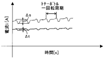
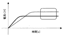
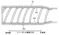
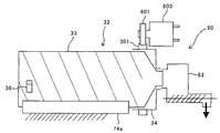
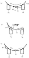
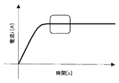
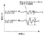
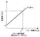
図10に示すグラフの四角で囲った範囲におけるモータ電流波形の拡大図。FIG. 11 is an enlarged view of a motor current waveform in a range surrounded by a square in the graph shown in FIG. 10. 実施形態に係るプリンタを示す概略構成図。1 is a schematic configuration diagram illustrating a printer according to an embodiment. Yトナー像を生成するためのプロセスユニットの構成を示す概略図。Schematic which shows the structure of the process unit for producing | generating a Y toner image. 本プリンタの電気回路の一部を示すブロック図。FIG. 2 is a block diagram showing a part of an electric circuit of the printer. トナー補給装置にトナー収容器が設置された状態を示す模式図。FIG. 4 is a schematic diagram illustrating a state where a toner container is installed in the toner supply device. 実施形態に係るトナー収容器を示す斜視図。FIG. 3 is a perspective view illustrating a toner container according to the embodiment. トナー収容器を装着する前のトナー補給装置と、トナー収容器の先端側端部とを示す拡大斜視図。FIG. 3 is an enlarged perspective view illustrating a toner replenishing device and a front end side end of the toner container before the toner container is mounted. トナー収容器を装着した状態のトナー補給装置と、トナー収容器の先端部とを示す縦断面図。FIG. 3 is a longitudinal sectional view showing a toner replenishing device in a state in which a toner container is mounted and a front end portion of the toner container. トナーボトルを回転させる際のモータ電流値の時間推移を示したグラフ。The graph which showed the time transition of the motor electric current value at the time of rotating a toner bottle. トナーボトルを回転させる際のモータ電流波形の一例を示したグラフ。The graph which showed an example of the motor current waveform at the time of rotating a toner bottle. 無回転時におけるトナーボトル内のトナーの粉面の状態を示す図。FIG. 4 is a diagram illustrating a state of a powder surface of toner in a toner bottle when there is no rotation. 無回転時から回転したときにおけるトナーボトル内のトナーの粉面の状態を示す図。FIG. 3 is a diagram illustrating a state of a toner powder surface in a toner bottle when rotating from a non-rotating time. 内周面に板状突起部を設けたトナーボトルを軸線方向と直交する方向で切断した断面図。FIG. 3 is a cross-sectional view of a toner bottle provided with a plate-like protrusion on an inner peripheral surface, cut in a direction perpendicular to the axial direction. 内周面に板状突起部を設けたトナーボトルを軸線方向で切断した断面図。FIG. 3 is a cross-sectional view of a toner bottle provided with a plate-like protrusion on an inner peripheral surface, cut in the axial direction. 実施形態2に係るトナー補給装置の模式図。FIG. 6 is a schematic diagram of a toner supply device according to a second embodiment. トナーボトルを後ろから見た図。The toner bottle is viewed from behind. トナーボトルを回転させる際のモータ電流波形の一例を示したグラフ。The graph which showed an example of the motor current waveform at the time of rotating a toner bottle. 図17に示すグラフの四角で囲った範囲における、三角突起部とガイド部とによりトナーボトルが振動したときのモータ電流波形の拡大図。FIG. 18 is an enlarged view of a motor current waveform when a toner bottle vibrates due to a triangular protrusion and a guide in a range surrounded by a square in the graph shown in FIG. 17. トナーボトル内のトナー量とモータ電流の変動幅との関係を示したグラフ。The graph which showed the relationship between the toner amount in a toner bottle, and the fluctuation range of a motor current.

[実施形態1]
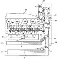
以下、本発明を適用した画像形成装置である電子写真方式のプリンタ(以下、単にプリンタ500という)の一実施形態について説明する。まず、本実施形態に係るプリンタの基本的な構成について説明する。図2は、実施形態に係るプリンタを示す概略構成図である。このプリンタは、イエロー、シアン、マゼンタ、ブラック(以下、Y、C、M、Kと記す。)用の4つのプロセスユニット1Y,1C,1M,1Kを備えている。これらは、画像を形成する画像形成物質として、互いに異なる色のY、C、M、Kのトナーを用いるが、それ以外は同様の構成になっている。
[Embodiment 1]
Hereinafter, an embodiment of an electrophotographic printer (hereinafter simply referred to as a printer 500), which is an image forming apparatus to which the present invention is applied, will be described. First, a basic configuration of the printer according to the present embodiment will be described. FIG. 2 is a schematic configuration diagram illustrating the printer according to the embodiment. The printer includes four process units 1Y, 1C, 1M, and 1K for yellow, cyan, magenta, and black (hereinafter referred to as Y, C, M, and K). These use Y, C, M, and K toners of different colors as image forming substances for forming an image, but the other configurations are the same.

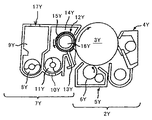
図3は、Yトナー像を生成するためのプロセスユニット1Yの構成を示す概略図である。プロセスユニット1Yは、感光体ユニット2Yと現像装置7Yとを有している。感光体ユニット2Y及び現像装置7Yは、プロセスユニット1Yとして一体的にプリンタ本体に対して着脱可能に構成されている。ただし、プリンタ本体から取り外した状態では、現像装置7Yを感光体ユニット2Yに対して着脱することができる。感光体ユニット2Yは、潜像担持体としてのドラム状の感光体3Y、ドラムクリーニング装置4Y、除電装置、帯電装置5Yなどを有している。帯電手段としての帯電装置5Yは、駆動手段によって図2中時計回り方向に回転駆動する感光体3Yの表面を帯電ローラ6Yにより一様帯電させる。具体的には、図3において、反時計回りに回転駆動する帯電ローラ6Yに対して電源から帯電バイアスを印加し、その帯電ローラ6Yを感光体3Yに近接又は接触させることで、感光体3Yを一様帯電させる。なお、帯電ローラ6Yの代わりに、帯電ブラシ等の他の帯電部材を近接又は接触させるものを用いてもよい。また、スコロトロンチャージャのように、チャージャ方式によって感光体3Yを一様帯電させるものを用いてもよい。帯電装置5Yによって一様帯電した感光体3Yの表面は、後述する潜像形成手段としての光書込ユニット20から発せられるレーザー光によって露光走査されてY用の静電潜像を担持する。   FIG. 3 is a schematic diagram showing a configuration of a process unit 1Y for generating a Y toner image. The process unit 1Y has a photoreceptor unit 2Y and a developing device 7Y. The photoconductor unit 2Y and the developing device 7Y are configured to be detachable from the printer main body integrally as the process unit 1Y. However, the developing device 7Y can be attached to and detached from the photoreceptor unit 2Y in a state where it is detached from the printer main body. The photoreceptor unit 2Y includes a drum-shaped photoreceptor 3Y as a latent image carrier, a drum cleaning device 4Y, a charge eliminating device, a charging device 5Y, and the like. The charging device 5Y as the charging means uniformly charges the surface of the photoreceptor 3Y, which is driven to rotate clockwise in FIG. 2 by the driving means, with the charging roller 6Y. Specifically, in FIG. 3, a charging bias is applied from a power source to a charging roller 6Y that is driven to rotate counterclockwise, and the charging roller 6Y is brought close to or in contact with the photoconductor 3Y, thereby causing the photoconductor 3Y to move. Charge uniformly. Instead of the charging roller 6Y, another charging member such as a charging brush may be used in proximity or contact. Further, a charger that uniformly charges the photosensitive member 3Y by a charger method, such as a scorotron charger, may be used. The surface of the photoreceptor 3Y uniformly charged by the charging device 5Y is exposed and scanned by a laser beam emitted from an optical writing unit 20 serving as a latent image forming unit, which will be described later, and carries an electrostatic latent image for Y.

現像手段としての現像装置7Yは、図3に示すように、現像剤搬送手段としての第一現像剤搬送スクリュウ8Yが配設された第一剤収容室9Yを有している。また、トナー濃度検出手段としての透磁率センサからなるトナー濃度センサ10Y、第二現像剤搬送スクリュウ11Y、現像ロール12Y、ドクターブレード13Yなどが配設された第二剤収容室14Yも有している。循環経路を形成しているこれら2つの剤収容室内には、磁性キャリアとマイナス帯電性のYトナーとからなる二成分現像剤であるY現像剤が内包されている。第一現像剤搬送スクリュウ8Yは、駆動手段によって回転駆動することで、第一剤収容室9Y内のY現像剤を図3中の手前側へ搬送する。搬送途中のY現像剤は、第一現像剤搬送スクリュウ8Yの上方に固定されたトナー濃度センサ10Yによって、第一剤収容室9Yにおけるトナー補給口17Yに対向する箇所(以下「補給位置」という。)よりも現像剤循環方向下流側に位置する所定の検出箇所を通過するY現像剤のトナー濃度が検知される。そして、第一現像剤搬送スクリュウ8Yにより第一剤収容室9Yの端部まで搬送されたY現像剤は、連通口18Yを経て第二剤収容室14Y内に進入する。第二剤収容室14Y内の第二現像剤搬送スクリュウ11Yは、駆動手段によって回転駆動することで、Y現像剤を図3中奥側へ搬送する。このようにしてY現像剤を搬送する第二現像剤搬送スクリュウ11Yの図3中上方には、現像ロール12Yが第二現像剤搬送スクリュウ11Yと平行な姿勢で配設されている。現像ロール12Yは、図3中反時計回り方向に回転駆動する非磁性スリーブからなる現像スリーブ15Y内に固定配置されたマグネットローラ16Yを内包した構成となっている。   As shown in FIG. 3, the developing device 7Y as the developing means has a first agent storage chamber 9Y in which a first developer conveying screw 8Y as a developer conveying means is disposed. Further, it also has a second agent storage chamber 14Y in which a toner concentration sensor 10Y comprising a magnetic permeability sensor as a toner concentration detecting means, a second developer conveying screw 11Y, a developing roll 12Y, a doctor blade 13Y and the like are disposed. . Y developer, which is a two-component developer composed of a magnetic carrier and a negatively chargeable Y toner, is contained in these two agent storage chambers forming a circulation path. The first developer conveying screw 8Y is rotationally driven by a driving unit to convey the Y developer in the first agent containing chamber 9Y to the near side in FIG. The Y developer in the middle of conveyance is a portion (hereinafter referred to as “replenishment position”) facing the toner replenishing port 17Y in the first agent storage chamber 9Y by the toner concentration sensor 10Y fixed above the first developer conveyance screw 8Y. ), The toner concentration of the Y developer passing through a predetermined detection position located downstream of the developer circulation direction is detected. Then, the Y developer transported to the end of the first agent storage chamber 9Y by the first developer transport screw 8Y enters the second agent storage chamber 14Y through the communication port 18Y. The second developer transport screw 11Y in the second agent storage chamber 14Y is rotationally driven by the driving means to transport the Y developer to the back side in FIG. In this way, the developing roller 12Y is arranged in a posture parallel to the second developer conveying screw 11Y above the second developer conveying screw 11Y that conveys the Y developer in FIG. The developing roll 12Y includes a magnet roller 16Y fixedly disposed in a developing sleeve 15Y made of a non-magnetic sleeve that is driven to rotate counterclockwise in FIG.

第二現像剤搬送スクリュウ11Yによって搬送されるY現像剤の一部は、マグネットローラ16Yの発する磁力によって現像スリーブ15Yの表面に汲み上げられる。そして、現像スリーブ15Yの表面と所定の間隙を保持するように配設されたドクターブレード13Yによってその層厚が規制された後、感光体3Yと対向する現像領域まで搬送され、感光体3Y上のY用の静電潜像にYトナーを付着させる。この付着により、感光体3Y上にYトナー像が形成される。現像によってYトナーを消費したY現像剤は、現像スリーブ15Yの回転に伴って第二現像剤搬送スクリュウ11Y上に戻される。そして、第二現像剤搬送スクリュウ11Yにより第二剤収容室14Yの端部まで搬送されたY現像剤は、連通口19Yを経て第一剤収容室9Y内に戻る。このようにして、Y現像剤は現像ユニット内を循環搬送される。   A part of the Y developer conveyed by the second developer conveying screw 11Y is pumped up to the surface of the developing sleeve 15Y by the magnetic force generated by the magnet roller 16Y. Then, after the layer thickness is regulated by a doctor blade 13Y disposed so as to maintain a predetermined gap from the surface of the developing sleeve 15Y, the layer is conveyed to a developing region facing the photosensitive member 3Y, and is transferred onto the photosensitive member 3Y. Y toner is adhered to the electrostatic latent image for Y. This adhesion forms a Y toner image on the photoreceptor 3Y. The Y developer that has consumed Y toner by the development is returned to the second developer conveying screw 11Y as the developing sleeve 15Y rotates. Then, the Y developer transported to the end of the second agent storage chamber 14Y by the second developer transport screw 11Y returns to the first agent storage chamber 9Y through the communication port 19Y. In this way, the Y developer is circulated and conveyed in the developing unit.

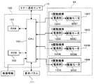
図4は、本プリンタの電気回路の一部を示すブロック図である。トナー濃度センサ10YによるY現像剤のトナー濃度の検出結果は、電気信号として制御部100に送られる。 この制御部100は、演算手段たるCPU(Central Processing Unit)101、記憶部であるRAM(Random Access Memory)102及びROM(Read Only Memory)103等を有している。そして、各種の演算処理や、制御プログラムの実行を行うことができる。制御部100は、RAM102の中にトナー濃度センサ10Yからの出力電圧の目標値であるY用の目標電圧Vtrefのデータを格納している。また、他の現像装置7C,7M,7Kに搭載された各トナー濃度センサ10C,10M,10Kからの出力電圧の目標値であるC,M,K用の目標電圧Vtrefのデータもそれぞれ格納している。   FIG. 4 is a block diagram showing a part of the electric circuit of the printer. The detection result of the toner concentration of the Y developer by the toner concentration sensor 10Y is sent to the control unit 100 as an electric signal. The control unit 100 includes a CPU (Central Processing Unit) 101 as a calculation means, a RAM (Random Access Memory) 102 as a storage unit, a ROM (Read Only Memory) 103, and the like. Various arithmetic processes and control programs can be executed. The control unit 100 stores data of the Y target voltage Vtref, which is the target value of the output voltage from the toner density sensor 10Y, in the RAM 102. Further, data of target voltages Vtref for C, M, and K, which are target values of output voltages from the toner density sensors 10C, 10M, and 10K mounted in the other developing devices 7C, 7M, and 7K, are also stored. Yes.

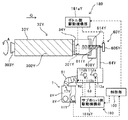
Y用の現像装置7Yについては、トナー濃度センサ10Yからの出力電圧の値とY用の目標電圧Vtrefを比較し、比較結果に応じた量のYトナーをトナー補給口17Yから供給するように、Y用のトナー補給装置60の駆動機構180Yを制御する。詳しくは、駆動機構180が、後述する収容器側駆動機構部181a(図5参照)とサブホッパ側駆動機構部181b(図5参照)とに分かれている。そして、収容器側駆動機構部181aに設けられた駆動モータ603Y(図8参照)と、サブホッパ側駆動機構部に設けられた駆動モータとの駆動を制御部100が制御する。例えば、駆動モータ603Yに電流を供給する電源部120Yを制御して、駆動モータ603Yを回転駆動させる。なお、駆動モータ603Yを流れるモータ電流値は、制御部100によって随時測定されている。また、収容器側駆動機構部181aとサブホッパ側駆動機構部181bとは、独立駆動となっている。この制御により、現像に伴うYトナーの消費によってYトナー濃度が低下したY現像剤に対し、第一剤収容室9Yで適量のYトナーが供給される。このため、第二剤収容室14Y内のY現像剤のトナー濃度は目標トナー濃度範囲内に維持される。他色用の現像装置7C,7M,7K内における現像剤についても同様である。   For the developing device 7Y for Y, the value of the output voltage from the toner density sensor 10Y is compared with the target voltage Vtref for Y, and an amount of Y toner corresponding to the comparison result is supplied from the toner supply port 17Y. The drive mechanism 180Y of the toner supply device 60 for Y is controlled. Specifically, the drive mechanism 180 is divided into a container side drive mechanism 181a (see FIG. 5) and a sub hopper side drive mechanism 181b (see FIG. 5), which will be described later. And the control part 100 controls the drive of the drive motor 603Y (refer FIG. 8) provided in the container side drive mechanism part 181a, and the drive motor provided in the sub hopper side drive mechanism part. For example, the power supply unit 120Y that supplies current to the drive motor 603Y is controlled to rotate the drive motor 603Y. Note that the value of the motor current flowing through the drive motor 603Y is measured by the control unit 100 as needed. Further, the container side drive mechanism 181a and the sub hopper side drive mechanism 181b are independently driven. With this control, an appropriate amount of Y toner is supplied in the first agent storage chamber 9Y to the Y developer whose Y toner density has decreased due to consumption of Y toner during development. For this reason, the toner concentration of the Y developer in the second agent storage chamber 14Y is maintained within the target toner concentration range. The same applies to the developers in the developing devices 7C, 7M, and 7K for other colors.

先に示した図2において、感光体3Y上に形成されたYトナー像は、中間転写体である中間転写ベルト41に中間転写される。感光体ユニット2Yのドラムクリーニング装置4Yは、中間転写工程を経た後の感光体3Yの表面に残留したトナーを除去する。これによってクリーニング処理が施された感光体3Yの表面は、除電装置によって除電される。この除電により、感光体3Yの表面が初期化されて次の画像形成に備えられる。他色用のプロセスユニット1C,1M,1Kにおいても、同様にして感光体3C,3M,3K上にCトナー像、Mトナー像、Kトナー像が形成されて、中間転写ベルト41上に中間転写される。   In FIG. 2 described above, the Y toner image formed on the photoreceptor 3Y is intermediately transferred to the intermediate transfer belt 41 which is an intermediate transfer body. The drum cleaning device 4Y of the photoreceptor unit 2Y removes toner remaining on the surface of the photoreceptor 3Y after the intermediate transfer process. As a result, the surface of the photoreceptor 3Y that has been subjected to the cleaning process is neutralized by the neutralization device. By this charge removal, the surface of the photoreceptor 3Y is initialized and prepared for the next image formation. Similarly, in the process units 1C, 1M, and 1K for other colors, C toner images, M toner images, and K toner images are formed on the photoreceptors 3C, 3M, and 3K, and the intermediate transfer belt 41 is subjected to intermediate transfer. Is done.

プロセスユニット1Y,1C,1M,1Kの図2中下方には、光書込ユニット20が配設されている。光書込ユニット20は、外部接続されたコンピュータなどから制御部100が取得した画像情報(画素情報)に基づいて発したレーザー光Lを、各プロセスユニット1Y,1C,1M,1Kの感光体3Y,3C,3M,3Kに照射する。これにより、感光体3Y,3C,3M,3K上には、それぞれY用、C用、M用、K用の静電潜像が形成される。なお、光書込ユニット20は、光源から発したレーザー光Lを、モータによって回転駆動されるポリゴンミラー21によって偏向せしめながら、複数の光学レンズやミラーを介して感光体3Y,3C,3M,3Kに照射するものである。かかる構成のものに代えて、LEDアレイを採用したものを用いてもよい。   An optical writing unit 20 is disposed below the process units 1Y, 1C, 1M, and 1K in FIG. The optical writing unit 20 emits a laser beam L based on image information (pixel information) acquired by the control unit 100 from an externally connected computer or the like to each of the process units 1Y, 1C, 1M, and 1K. , 3C, 3M, 3K. As a result, electrostatic latent images for Y, C, M, and K are formed on the photoreceptors 3Y, 3C, 3M, and 3K, respectively. The optical writing unit 20 deflects the laser light L emitted from the light source by the polygon mirror 21 that is rotationally driven by a motor, and passes through the photoreceptors 3Y, 3C, 3M, and 3K via a plurality of optical lenses and mirrors. Is irradiated. Instead of such a configuration, an LED array may be used.

光書込ユニット20の下方には、第一給紙カセット22、第二給紙カセット23が鉛直方向に重なるように配設されている。これらの給紙カセット内には、それぞれ、記録材である記録紙Pが複数枚重ねられた記録紙束の状態で収容されており、一番上の記録紙Pには、第一給紙ローラ22a及び第二給紙ローラ23aがそれぞれ当接している。第一給紙ローラ22aが駆動手段によって図2中反時計回りに回転駆動すると、第一給紙カセット22内の一番上の記録紙Pが、カセットの図2中右側方において鉛直方向に延在するように配設された給紙路24に向けて排出される。また、第二給紙ローラ23aが駆動手段によって図2中反時計回りに回転駆動すると、第二給紙カセット23内の一番上の記録紙Pが給紙路24に向けて排出される。   A first paper feed cassette 22 and a second paper feed cassette 23 are disposed below the optical writing unit 20 so as to overlap in the vertical direction. In each of these paper feed cassettes, a plurality of recording papers P, which are recording materials, are stored in a bundle of recording papers, and the top recording paper P includes a first paper feed roller. 22a and the second paper feed roller 23a are in contact with each other. When the first paper feed roller 22a is driven to rotate counterclockwise in FIG. 2 by the driving means, the uppermost recording paper P in the first paper feed cassette 22 extends vertically on the right side of the cassette in FIG. The paper is discharged toward the paper feed path 24 arranged to exist. Further, when the second paper feeding roller 23 a is driven to rotate counterclockwise in FIG. 2 by the driving means, the uppermost recording paper P in the second paper feeding cassette 23 is discharged toward the paper feeding path 24.

給紙路24内には、複数の搬送ローラ対25が配設されており、給紙路24に送り込まれた記録紙Pは、これら搬送ローラ対25のローラ間に挟み込まれながら、給紙路24内を図2中下側から上側に向けて搬送される。また、給紙路24の末端には、レジストローラ対26が配設されている。レジストローラ対26は、搬送ローラ対25から送られてくる記録紙Pをローラ間に挟み込むとすぐに、両ローラの回転を一旦停止させる。そして、記録紙Pを適切なタイミングで後述の二次転写ニップに向けて送り出す。   A plurality of transport roller pairs 25 are arranged in the paper feed path 24, and the recording paper P fed into the paper feed path 24 is sandwiched between the rollers of the transport roller pair 25 while being fed. 2 is conveyed from the lower side to the upper side in FIG. A registration roller pair 26 is disposed at the end of the paper feed path 24. The registration roller pair 26 temporarily stops the rotation of both rollers as soon as the recording paper P sent from the conveyance roller pair 25 is sandwiched between the rollers. Then, the recording paper P is sent out toward a secondary transfer nip described later at an appropriate timing.

各プロセスユニット1Y,1C,1M,1Kの図2中上方には、中間転写ベルト41を張架しながら図2中反時計回りに無端移動させる転写ユニット40が配設されている。転写ユニット40は、中間転写ベルト41のほか、ベルトクリーニングユニット、4つの一次転写ローラ45Y,45C,45M,45K、二次転写バックアップローラ46、駆動ローラ47、テンションローラ49などを備えている。中間転写ベルト41は、これらのローラに張架されながら、駆動ローラ47の回転駆動によって図2中反時計回りに無端移動する。4つの一次転写ローラ45Y,45C,45M,45Kは、このように無端移動する中間転写ベルト41を感光体3Y,3C,3M,3Kとの間に挟み込んでそれぞれ一次転写ニップを形成している。そして、中間転写ベルト41の内周面にトナーとは逆極性(本実施形態ではプラス極性)の転写バイアスを印加する。中間転写ベルト41は、その無端移動に伴ってY用、C用、M用、K用の一次転写ニップを順次通過していく過程で、その外周面に感光体3Y,3C,3M,3K上の各色トナー像が重なり合うように一次転写される。これにより、中間転写ベルト41上に4色重ね合わせトナー像(以下「4色トナー像」という。)が形成される。   Above each of the process units 1Y, 1C, 1M, and 1K in FIG. 2, a transfer unit 40 that endlessly moves counterclockwise in FIG. 2 while stretching the intermediate transfer belt 41 is disposed. In addition to the intermediate transfer belt 41, the transfer unit 40 includes a belt cleaning unit, four primary transfer rollers 45Y, 45C, 45M, and 45K, a secondary transfer backup roller 46, a drive roller 47, and a tension roller 49. The intermediate transfer belt 41 is endlessly moved counterclockwise in FIG. 2 by the rotation of the driving roller 47 while being stretched around these rollers. The four primary transfer rollers 45Y, 45C, 45M, and 45K sandwich the intermediate transfer belt 41 that moves endlessly between the photoreceptors 3Y, 3C, 3M, and 3K to form primary transfer nips. A transfer bias having a polarity opposite to that of the toner (in this embodiment, a positive polarity) is applied to the inner peripheral surface of the intermediate transfer belt 41. As the endless movement of the intermediate transfer belt 41 passes through the primary transfer nips for Y, C, M, and K in sequence, the intermediate transfer belt 41 is placed on the outer surface of the photoreceptor 3Y, 3C, 3M, 3K. The color toner images are primarily transferred so as to overlap each other. As a result, a four-color superimposed toner image (hereinafter referred to as “four-color toner image”) is formed on the intermediate transfer belt 41.

二次転写バックアップローラ46は、中間転写ベルト41のループ外側に配設された二次転写ローラ50との間に中間転写ベルト41を挟み込んで二次転写ニップを形成している。先に説明したレジストローラ対26は、ローラ間に挟み込んだ記録紙Pを、中間転写ベルト41上の4色トナー像に同期させ得るタイミングで、二次転写ニップに向けて送り出す。中間転写ベルト41上の4色トナー像は、二次転写バイアスが印加される二次転写ローラ50と二次転写バックアップローラ46との間に形成される二次転写電界や、ニップ圧の影響により、二次転写ニップ内で記録紙Pに一括二次転写される。そして、記録紙Pの白色と相まって、フルカラートナー像となる。二次転写ニップを通過した後の中間転写ベルト41には、記録紙Pに転写されなかった転写残トナーが付着している。これは、ベルトクリーニングユニットによってクリーニングされる。なお、ベルトクリーニングユニットは、クリーニングブレードなどのクリーニング部材を中間転写ベルト41のおもて面に当接させており、これによってベルト上の転写残トナーを掻き取って除去するものである。   The secondary transfer backup roller 46 sandwiches the intermediate transfer belt 41 with the secondary transfer roller 50 disposed outside the loop of the intermediate transfer belt 41 to form a secondary transfer nip. The registration roller pair 26 described above feeds the recording paper P sandwiched between the rollers toward the secondary transfer nip at a timing at which the recording paper P can be synchronized with the four-color toner image on the intermediate transfer belt 41. The four-color toner image on the intermediate transfer belt 41 is affected by the secondary transfer electric field formed between the secondary transfer roller 50 to which the secondary transfer bias is applied and the secondary transfer backup roller 46, and the influence of the nip pressure. Then, the secondary transfer is batch-transferred onto the recording paper P in the secondary transfer nip. Then, combined with the white color of the recording paper P, a full color toner image is obtained. Transfer residual toner that has not been transferred to the recording paper P adheres to the intermediate transfer belt 41 after passing through the secondary transfer nip. This is cleaned by a belt cleaning unit. In the belt cleaning unit, a cleaning member such as a cleaning blade is brought into contact with the front surface of the intermediate transfer belt 41, whereby the transfer residual toner on the belt is scraped off and removed.

二次転写ニップの図中上方には、定着手段としての定着装置80が配設されている。この定着装置80は、ハロゲンランプ等の発熱源を内包する加圧加熱ローラ81と、定着ベルトユニット82とを備えている。定着ベルトユニット82は、定着ベルト84、ハロゲンランプ等の発熱源を内包する加熱ローラ83、テンションローラ85、駆動ローラ86、温度センサ等を有している。そして、無端状の定着ベルト84を加熱ローラ83、テンションローラ85及び駆動ローラ86によって張架しながら、図2中反時計回り方向に無端移動せしめる。この無端移動の過程で、定着ベルト84は加熱ローラ83によって裏面側から加熱される。このようにして加熱される定着ベルト84の加熱ローラ83の掛け回し箇所には、図2中時計回り方向に回転駆動される加圧加熱ローラ81がおもて面側から当接している。これにより、加圧加熱ローラ81と定着ベルト84とが当接する定着ニップが形成されている。定着ベルト84のループ外側には、温度センサが定着ベルト84のおもて面と所定の間隙を介して対向するように配設されており、定着ニップに進入する直前の定着ベルト84の表面温度を検知する。この検知結果は、定着電源回路に送られる。定着電源回路は、温度センサによる検知結果に基づいて、加熱ローラ83に内包される   A fixing device 80 as a fixing unit is disposed above the secondary transfer nip in the drawing. The fixing device 80 includes a pressure heating roller 81 that includes a heat source such as a halogen lamp, and a fixing belt unit 82. The fixing belt unit 82 includes a fixing roller 84, a heating roller 83 containing a heat source such as a halogen lamp, a tension roller 85, a driving roller 86, a temperature sensor, and the like. Then, the endless fixing belt 84 is endlessly moved in the counterclockwise direction in FIG. 2 while being stretched by the heating roller 83, the tension roller 85, and the driving roller 86. In the process of endless movement, the fixing belt 84 is heated from the back side by the heating roller 83. A pressure heating roller 81 that is driven to rotate in the clockwise direction in FIG. 2 is in contact with the surface of the fixing belt 84 that is heated in this manner. Thus, a fixing nip where the pressure heating roller 81 and the fixing belt 84 abut is formed. A temperature sensor is disposed outside the loop of the fixing belt 84 so as to face the front surface of the fixing belt 84 with a predetermined gap, and the surface temperature of the fixing belt 84 immediately before entering the fixing nip. Is detected. This detection result is sent to the fixing power supply circuit. The fixing power supply circuit is included in the heating roller 83 based on the detection result of the temperature sensor.

発熱源や、加圧加熱ローラ81に内包される発熱源に対する電源の供給をオンオフ制御する。これにより、定着ベルト84の表面温度が約140[℃]に維持される。二次転写ニップを通過した記録紙Pは、中間転写ベルト41から分離した後、定着装置80内に送られる。そして、定着装置80内の定着ニップに挟まれながら図中下側から上側に向けて搬送される過程で、定着ベルト84によって加熱されたり、押圧されたりして、フルカラートナー像が記録紙Pに定着する。このようにして定着処理が施された記録紙Pは、排紙ローラ対87のローラ間を経た後、機外へと排出される。プリンタ本体の筺体の上面には、スタック部88が形成されており、排紙ローラ対87によって機外に排出された記録紙Pは、このスタック部88に順次スタックされる。   On / off control of power supply to the heat source and the heat source included in the pressure heating roller 81 is performed. As a result, the surface temperature of the fixing belt 84 is maintained at about 140 [° C.]. The recording paper P that has passed through the secondary transfer nip is separated from the intermediate transfer belt 41 and then fed into the fixing device 80. Then, in the process of being conveyed from the lower side to the upper side in the figure while being sandwiched between the fixing nips in the fixing device 80, the full-color toner image is applied to the recording paper P by being heated or pressed by the fixing belt 84. To settle. The recording sheet P subjected to the fixing process in this manner is discharged outside the apparatus after passing between the rollers of the discharge roller pair 87. A stack unit 88 is formed on the top surface of the printer body, and the recording paper P discharged to the outside by the discharge roller pair 87 is sequentially stacked on the stack unit 88.

転写ユニット40の上方には、Yトナー、Cトナー、Mトナー、Kトナーをそれぞれ収容する4つのトナー収納容器であるトナー収容器32Y,32C,32M,32Kがトナーボトル収納部に配設されている。トナー収容器32Y,32C,32M,32K内の各色トナーは、トナー補給装置60により、それぞれ、プロセスユニット1Y,1C,1M,1Kの現像装置7Y,7C,7M,7Kに適宜供給される。トナー収容器32Y,32C,32M,32Kは、プロセスユニット1Y,1C,1M,1Kとは独立してプリンタ本体に脱着可能である。   Above the transfer unit 40, toner containers 32Y, 32C, 32M, and 32K, which are four toner storage containers for storing Y toner, C toner, M toner, and K toner, are disposed in the toner bottle storage section. Yes. The color toners in the toner containers 32Y, 32C, 32M, and 32K are appropriately supplied by the toner replenishing device 60 to the developing devices 7Y, 7C, 7M, and 7K of the process units 1Y, 1C, 1M, and 1K, respectively. The toner containers 32Y, 32C, 32M, and 32K are detachable from the printer main body independently of the process units 1Y, 1C, 1M, and 1K.

先に図3に示したように、トナー濃度センサ10Yは、非供給領域としての第一剤収容室9Y内において、供給領域としての第二剤収容室14Yに進入する直前の現像剤のトナー濃度を検知する。また、トナー補給口17Yは、第二剤収容室14Yから第一剤収容室9Y内に進入した直後の現像剤に対してトナーを補給する位置に設けられている。つまり、第一剤収容室9Y内において、トナー濃度センサ10Yは、トナー補給口17Yよりも下流側の位置で現像剤のトナー濃度を検知する。   As shown in FIG. 3, the toner concentration sensor 10Y has a toner concentration in the developer immediately before entering the second agent storage chamber 14Y as the supply region in the first agent storage chamber 9Y as the non-supply region. Is detected. The toner supply port 17Y is provided at a position for supplying toner to the developer immediately after entering the first agent storage chamber 9Y from the second agent storage chamber 14Y. That is, in the first agent storage chamber 9Y, the toner concentration sensor 10Y detects the toner concentration of the developer at a position downstream of the toner supply port 17Y.

次に、トナー補給装置60Y,60C,60M,60Kについて説明する。図5は、トナー補給装置60Yにトナー収容器32Yが設置された状態を示す模式図である。収容器搭載部70に設置されたトナー収容器32Y,32C,32M,32K内のトナーは、各色の現像装置7Y,7C,7M,7K内のトナー消費に応じて、トナー色ごとに設けられたトナー補給装置60Y,60C,60M,60Kによって適宜に各現像装置7Y,7C,7M,7K内に補給される。なお、4つのトナー補給装置60Y,60C,60M,60Kやトナー収容器32Y,32C,32M,32Kは、作像プロセスに用いられるトナーの色が異なる以外はほぼ同一構造である。このため、以下、イエローに対応したトナー補給装置60Yやトナー収容器32Yのみの説明を行い、他の3つの色に対応したトナー補給装置60C,60M,60Kやトナー収容器32C,32M,32Kの説明を適宜に省略する。   Next, the toner replenishing devices 60Y, 60C, 60M, and 60K will be described. FIG. 5 is a schematic diagram illustrating a state where the toner container 32Y is installed in the toner replenishing device 60Y. The toner in the toner containers 32Y, 32C, 32M, and 32K installed in the container mounting portion 70 is provided for each toner color according to the toner consumption in the developing devices 7Y, 7C, 7M, and 7K of the respective colors. The developing devices 7Y, 7C, 7M, and 7K are appropriately replenished by the toner replenishing devices 60Y, 60C, 60M, and 60K. The four toner replenishing devices 60Y, 60C, 60M, and 60K and the toner containers 32Y, 32C, 32M, and 32K have substantially the same structure except that the colors of toner used in the image forming process are different. Therefore, only the toner replenishing device 60Y and toner container 32Y corresponding to yellow will be described below, and the toner replenishing devices 60C, 60M, and 60K and toner containers 32C, 32M, and 32K corresponding to the other three colors will be described. The description will be omitted as appropriate.

トナー補給装置60Y,60C,60M,60Kは、収容器搭載部70、搬送ノズル611Y,611C,611M,611K、搬送スクリュウ614Y,614C,614M,614K、トナー落下搬送路64Y,64C,64M,64K、駆動機構180Y,180C,180M,180K等で構成されている。トナー収容器32Yが図中矢印Q方向へ差し込まれ収容器搭載部70に装着されると、その装着動作に連動してトナー収容器32Yの先端側からトナー補給装置60Yの搬送ノズル611Yが挿入され、トナー収容器32Y内と搬送ノズル611Y内とが連通する。トナー収容器32Yは、円筒状の形状になっており、収容器搭載部70に非回転の状態で固定される容器先端カバー34Yや、容器回転ギヤ301Yが一体的に形成されたトナーボトル33Yなどから構成されている。保持部としての容器先端カバー34Yは、トナーボトル33Yの回転軸線方向の先端部を受け入れた状態で、トナーボトル33Yを回転可能に保持する。   The toner replenishing devices 60Y, 60C, 60M, and 60K include a container mounting portion 70, transport nozzles 611Y, 611C, 611M, and 611K, transport screws 614Y, 614C, 614M, and 614K, toner dropping transport paths 64Y, 64C, 64M, and 64K, The drive mechanism is composed of 180Y, 180C, 180M, 180K, and the like. When the toner container 32Y is inserted in the direction of the arrow Q in the drawing and attached to the container mounting portion 70, the transport nozzle 611Y of the toner replenishing device 60Y is inserted from the front end side of the toner container 32Y in conjunction with the mounting operation. The inside of the toner container 32Y and the inside of the transport nozzle 611Y communicate with each other. The toner container 32Y has a cylindrical shape, such as a container tip cover 34Y fixed to the container mounting portion 70 in a non-rotating state, a toner bottle 33Y integrally formed with a container rotation gear 301Y, and the like. It is composed of The container front end cover 34Y as a holding unit rotatably holds the toner bottle 33Y while receiving the front end of the toner bottle 33Y in the rotation axis direction.

収容器搭載部70は、先端受部73や容器受部72や挿入口形成部71等から構成されている。先端受部73は、トナー収容器32Yの容器先端カバー34Yを固定するためのものである。容器受部72は、トナー収容器32Yのトナーボトル33Yを受けるためのものである。挿入口形成部71は、トナー収容器32Yの装着動作時における挿入口を形成するものである。   The container mounting part 70 is comprised from the front-end | tip receiving part 73, the container receiving part 72, the insertion port formation part 71 grade | etc.,. The tip receiving portion 73 is for fixing the container tip cover 34Y of the toner container 32Y. The container receiver 72 is for receiving the toner bottle 33Y of the toner container 32Y. The insertion port forming part 71 forms an insertion port during the mounting operation of the toner container 32Y.

プリンタの手前側(図2の紙面垂直方向手前側)に設置された本体カバーを開放すると、収容器搭載部70の挿入口形成部71が露呈される。そして、各トナー収容器32Y,32C,32M,32Kの長手方向を水平方向とした状態で、プリンタの手前側から各トナー収容器32Y,32C,32M,32Kの着脱操作(トナー収容器32の長手方向を着脱方向とする着脱操作)を行う。なお、図5中のセットカバー608Yは、収容器搭載部70の先端受部73の一部である。   When the main body cover installed on the front side of the printer (the front side in the direction perpendicular to the paper in FIG. 2) is opened, the insertion port forming portion 71 of the container mounting portion 70 is exposed. The toner containers 32Y, 32C, 32M, and 32K are attached and detached from the front side of the printer with the longitudinal direction of the toner containers 32Y, 32C, 32M, and 32K set to the horizontal direction (the length of the toner container 32). An attachment / detachment operation with the direction as the attachment / detachment direction is performed. 5 is a part of the tip receiving portion 73 of the container mounting portion 70.

容器受部72は、その長手方向の長さが、トナーボトル33Yの長手方向の長さとほぼ同等になるように形成されている。また、先端受部73は容器受部72における長手方向(着脱方向)の一端側に設けられ、挿入口形成部71は容器受部72における長手方向の他端側に設けられている。容器先端カバー34Yは、トナー収容器32Yの装着動作に伴って、挿入口形成部71を通過した後に、しばらく容器受部72上を滑動して、その後に先端受部73に装着される。容器先端カバー34Yが先端受部73に装着された状態で、駆動モータ603Yや駆動ギヤ等で構成されている駆動機構180Yが容器回転ギヤ301Yに回転駆動力を伝達することで、トナーボトル33Yが図5中の矢印A方向に回転駆動される。   The container receiving portion 72 is formed so that its length in the longitudinal direction is substantially equal to the length of the toner bottle 33Y in the longitudinal direction. Further, the tip receiving portion 73 is provided on one end side in the longitudinal direction (attachment / detachment direction) of the container receiving portion 72, and the insertion port forming portion 71 is provided on the other end side in the longitudinal direction of the container receiving portion 72. The container tip cover 34Y slides on the container receiving portion 72 for a while after passing through the insertion port forming portion 71 in accordance with the mounting operation of the toner container 32Y, and is then attached to the tip receiving portion 73. With the container front end cover 34Y mounted on the front end receiving portion 73, the drive mechanism 180Y configured by the drive motor 603Y, the drive gear, and the like transmits the rotational driving force to the container rotation gear 301Y, so that the toner bottle 33Y is It is rotationally driven in the direction of arrow A in FIG.

なお、駆動モータ603としては、インナーローラ型DCブラシレスモータを用いることができる。この場合、周方向に所定の角度間隔で所定数のスリットを有するエンコーダディスクを、モータの出力軸の回転とともに回転するように、前記出力軸に対して垂直かつ同心にて固定して設ける。また、エンコーダディスクを挟み込む状態でモータに光学センサであるフォトセンサを取り付ける。そして、エンコーダディスクのスリットによりフォトセンサの光路の伝達と遮断とがなされ、フォトセンサから出力されたパルス信号を制御部100で計測することにより、モータの回転量や回転速度を導出するように構成してもよい。   As the drive motor 603, an inner roller type DC brushless motor can be used. In this case, an encoder disk having a predetermined number of slits at predetermined angular intervals in the circumferential direction is provided fixed perpendicularly and concentrically to the output shaft so as to rotate with the rotation of the output shaft of the motor. In addition, a photo sensor, which is an optical sensor, is attached to the motor in a state where the encoder disk is sandwiched. The optical path of the photosensor is transmitted and blocked by the slits of the encoder disk, and the pulse amount output from the photosensor is measured by the control unit 100 to derive the rotation amount and rotation speed of the motor. May be.

トナーボトル33Y自体が回転することで、トナーボトル33Yの内周面に螺旋状に形成された螺旋状突起302Yによって、トナーボトル33Yの内部に収容されたトナーがボトルの後端側から先端側(図5中の左側から右側)に搬送される。そして、容器先端カバー34Y側から搬送ノズル611Y内に供給される。搬送ノズル611Y内には、搬送スクリュウ614Yが配置されており、駆動機構180Yから搬送スクリュウギヤ605Yに回転駆動が入力されることで、搬送スクリュウ614Yが回転して搬送ノズル611Y内のトナーを搬送する。搬送ノズル611Yの搬送方向下流端は、トナー落下搬送路64Yに接続されており、搬送スクリュウ614Yによって搬送されたトナーは、トナー落下搬送路64Yを自重落下してサブホッパ63Y内に搬送される。   By rotating the toner bottle 33Y itself, the toner contained in the toner bottle 33Y is transferred from the rear end side to the front end side (from the rear end side of the bottle) by the spiral protrusion 302Y formed spirally on the inner peripheral surface of the toner bottle 33Y. It is conveyed from the left side to the right side in FIG. And it is supplied in the conveyance nozzle 611Y from the container front end cover 34Y side. A transport screw 614Y is disposed in the transport nozzle 611Y, and the transport screw 614Y rotates and transports the toner in the transport nozzle 611Y when rotation driving is input from the drive mechanism 180Y to the transport screw gear 605Y. . The downstream end in the transport direction of the transport nozzle 611Y is connected to the toner drop transport path 64Y, and the toner transported by the transport screw 614Y falls in its own weight on the toner drop transport path 64Y and is transported into the sub hopper 63Y.

トナー収容器32Y,32C,32M,32Kは、それぞれ、寿命に達したとき(収容するトナーがほとんどすべて消費されて空になったとき)に新品のものに交換される。トナー収容器32の長手方向における容器先端カバー34とは反対側の端部には把手部303が設けられており、交換の際には、作業者が把手部303を握って引き出すことで、装着されたトナー収容器32を取り外すことができる。   Each of the toner containers 32Y, 32C, 32M, and 32K is replaced with a new one when it reaches the end of its life (when almost all the toner to be stored is consumed and emptied). A handle 303 is provided at the end of the toner container 32 opposite to the container tip cover 34 in the longitudinal direction. When replacing, the operator holds the handle 303 and pulls it out. The toner container 32 can be removed.

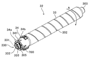
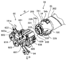
次に、トナー収容器32Y,32C,32M,32K及びトナー補給装置60Y,60C,60M,60Kについてより詳細に説明する。なお、上述したように、トナー収容器32Y,32C,32M,32K及びトナー補給装置60Y,60C,60M,60Kは、それぞれ使用するトナーの色が異なる他はほぼ同様の構成になっているので、以下、Y,C,M,Kという使用するトナーの色を示す添字を省略して説明する。図6は、実施形態に係るトナー収容器32を示す斜視図である。図7は、トナー収容器32を装着する前のトナー補給装置60と、トナー収容器32の先端側端部とを示す拡大斜視図である。図8は、トナー収容器32を装着した状態のトナー補給装置60と、トナー収容器32の先端部とを示す縦断面図である。   Next, the toner containers 32Y, 32C, 32M, and 32K and the toner replenishing devices 60Y, 60C, 60M, and 60K will be described in more detail. As described above, the toner containers 32Y, 32C, 32M, and 32K and the toner replenishing devices 60Y, 60C, 60M, and 60K have substantially the same configuration except that the colors of the toners used are different. In the following description, the suffixes Y, C, M, and K indicating the colors of the toners to be used are omitted. FIG. 6 is a perspective view showing the toner container 32 according to the embodiment. FIG. 7 is an enlarged perspective view showing the toner replenishing device 60 before the toner container 32 is mounted and the front end side end of the toner container 32. FIG. 8 is a longitudinal sectional view showing the toner replenishing device 60 with the toner container 32 attached and the tip of the toner container 32.

トナー補給装置60は、内部に搬送スクリュウ614を具備する搬送ノズル611を備えている。また、ノズルシャッタ部材612も備えている。ノズルシャッタ部材612は、トナー収容器32が装着される前の非装着時(図7の状態)において、搬送ノズル611に形成されたノズル開口部610を閉鎖する。また、トナー収容器32が装着された装着時(図8の状態)において、ノズル開口部610を開放する。トナー収容器32の先端面の中央には、装着時に搬送ノズル611が挿入されるノズル受入口331や、非装着時にノズル受入口331を閉鎖する容器シャッタ部材332が設けられている。   The toner replenishing device 60 includes a transport nozzle 611 having a transport screw 614 therein. A nozzle shutter member 612 is also provided. The nozzle shutter member 612 closes the nozzle opening 610 formed in the transport nozzle 611 when the toner container 32 is not mounted before being mounted (the state shown in FIG. 7). Further, when the toner container 32 is mounted (the state shown in FIG. 8), the nozzle opening 610 is opened. In the center of the front end surface of the toner container 32, a nozzle receiving port 331 into which the transport nozzle 611 is inserted when mounted and a container shutter member 332 that closes the nozzle receiving port 331 when not mounted are provided.

トナー収容器32の容器先端カバー34には、トナー補給装置60のセットカバー608に設けられた容器ロック部材609を容器外側から内側に向けて貫通させるためのロック用開口339が設けられている。また、容器先端カバー34には、トナー収容器32の使用状況等のデータを記録したIDチップ700も設けられている。さらには、収納するトナーの色が異なるトナー収容器32が他の色のセットカバー608に装着されることを防止する色非互換リブ34bも設けられている。   The container front end cover 34 of the toner container 32 is provided with a lock opening 339 for allowing the container lock member 609 provided on the set cover 608 of the toner replenishing device 60 to penetrate from the outside of the container toward the inside. The container tip cover 34 is also provided with an ID chip 700 that records data such as the usage status of the toner container 32. Furthermore, a color non-compatible rib 34b is provided to prevent the toner container 32 having a different toner color from being attached to the set cover 608 of another color.

図7に示されるように、トナー補給装置60は、プリンタ本体のフレームに対して搬送ノズル611を固定するノズルホルダ607を備え、ノズルホルダ607に対して、セットカバー608が固定されている。さらに、ノズルホルダ607には、搬送ノズル611の下方から搬送ノズル611の内部に連通するように配置されたトナー落下搬送路64が固定されている。トナー落下搬送路64は、装置高さ方向である縦方向に延びている。このトナー落下搬送路64内では、搬送スクリュウ614によって搬送されたトナーを落下させており、トナー落下搬送路64内が常時空洞になるようにしている。そして、トナー収容器32からトナー落下搬送路64を通ってサブホッパ63内にトナーが搬送される。また、トナー落下搬送路64内には、コイル状の揺動部材が設けられている。そして、トナー落下搬送路64内で揺動部材を揺動させることで、トナー落下搬送路64の内壁面に付着したトナーを落とすなどして、トナー落下搬送路64内にトナーが滞留するのを抑制している。   As shown in FIG. 7, the toner replenishing device 60 includes a nozzle holder 607 that fixes the transport nozzle 611 to the frame of the printer body, and a set cover 608 is fixed to the nozzle holder 607. Further, a toner dropping conveyance path 64 is fixed to the nozzle holder 607 so as to communicate with the inside of the conveyance nozzle 611 from below the conveyance nozzle 611. The toner dropping conveyance path 64 extends in the vertical direction which is the apparatus height direction. In the toner drop transport path 64, the toner transported by the transport screw 614 is dropped, so that the toner drop transport path 64 is always hollow. Then, the toner is conveyed from the toner container 32 through the toner dropping conveyance path 64 into the sub hopper 63. In addition, a coil-like swing member is provided in the toner dropping conveyance path 64. Then, by swinging the swinging member in the toner dropping conveyance path 64, the toner adhering to the inner wall surface of the toner dropping conveyance path 64 is dropped, for example, so that the toner stays in the toner dropping conveyance path 64. Suppressed.

フレーム602には、駆動機構180が固定されている。駆動機構180は、駆動モータ603及び容器駆動出力ギヤ601や、容器駆動出力ギヤ601の回転軸に駆動モータ603の回転駆動を伝達するウォームギヤ603aなどを有している。容器駆動出力ギヤ601の回転軸には、駆動伝達ギヤ604が固定されており、搬送スクリュウ614の回転軸に固定された搬送スクリュウギヤ605と噛み合う構成となっている。このような構成により、駆動モータ603を回転駆動させることで、容器駆動出力ギヤ601及び容器回転ギヤ301を介してトナー収容器32を回転させる。そして、駆動伝達ギヤ604及び搬送スクリュウギヤ605を介して、搬送スクリュウ614を回転させる。なお、駆動モータ603から容器回転ギヤ301までの駆動伝達経路や、駆動モータ603から搬送スクリュウギヤ605までの駆動伝達経路にクラッチを設けても良い。このようなクラッチを設けることで、駆動モータ603を回転駆動させたときに、トナー収容器32と搬送スクリュウ614との何れか一方のみを回転させる構成を実現できる。   A drive mechanism 180 is fixed to the frame 602. The drive mechanism 180 includes a drive motor 603 and a container drive output gear 601, a worm gear 603 a that transmits the rotational drive of the drive motor 603 to the rotation shaft of the container drive output gear 601, and the like. A drive transmission gear 604 is fixed to the rotating shaft of the container drive output gear 601, and is configured to mesh with the conveying screw gear 605 fixed to the rotating shaft of the conveying screw 614. With such a configuration, the toner container 32 is rotated via the container drive output gear 601 and the container rotation gear 301 by rotating the drive motor 603. Then, the transport screw 614 is rotated via the drive transmission gear 604 and the transport screw gear 605. A clutch may be provided in a drive transmission path from the drive motor 603 to the container rotation gear 301 or a drive transmission path from the drive motor 603 to the transport screw gear 605. By providing such a clutch, it is possible to realize a configuration in which only one of the toner container 32 and the conveying screw 614 is rotated when the drive motor 603 is driven to rotate.

次に、トナー収容器32のトナー補給装置60に対する装着過程について説明する。図7の図中矢印Qで示されるように、トナー補給装置60の方向にトナー収容器32が移動すると、搬送ノズル611のノズル先端部611aが容器シャッタ部材332の先端側の端面に接触する。トナー収容器32が更にトナー補給装置60の方向に移動すると、搬送ノズル611が容器シャッタ部材332の先端側の端面を押圧する。これによって容器シャッタバネ336が縮むと、容器シャッタ部材332がトナー収容器32の内部側(後端側)に押し込まれるとともに、搬送ノズル611のノズル先端側がノズル受入口331に挿入される。このとき、ノズルシャッタ部材612におけるノズルシャッタ鍔部612aよりもノズル先端側のノズルシャッタ筒状部612bも、搬送ノズル611とともにノズル受入口331に挿入される。   Next, a process of attaching the toner container 32 to the toner supply device 60 will be described. As indicated by an arrow Q in FIG. 7, when the toner container 32 moves in the direction of the toner replenishing device 60, the nozzle tip 611 a of the transport nozzle 611 contacts the end surface on the tip side of the container shutter member 332. When the toner container 32 further moves in the direction of the toner replenishing device 60, the transport nozzle 611 presses the end surface on the front end side of the container shutter member 332. Thus, when the container shutter spring 336 contracts, the container shutter member 332 is pushed into the inner side (rear end side) of the toner container 32 and the nozzle front end side of the transport nozzle 611 is inserted into the nozzle receiving port 331. At this time, the nozzle shutter cylindrical portion 612 b on the nozzle tip side of the nozzle shutter flange 612 a in the nozzle shutter member 612 is also inserted into the nozzle receiving port 331 together with the transport nozzle 611.

トナー収容器32が更にトナー補給装置60の方向に移動すると、ノズルシャッタ鍔部612aのノズルシャッタバネ受け面とは反対側の面が、容器シール部材333の先端側の端面に接触して容器シール部材333を少し押し潰す。これにより、ノズルシャッタ鍔部612aのノズルシャッタバネ受け面とは反対側の面がノズルシャッタ突き当てリブに突き当たることで、ノズルシャッタ部材612のトナー収容器32に対する回転軸方向の相対的位置が固定される。トナー収容器32がトナー補給装置60の方向に更に移動すると、搬送ノズル611がさらにトナー収容器32の内部側に挿入される。このとき、前記ノズルシャッタ突き当てリブに突き当たっていたノズルシャッタ部材612は、搬送ノズル611に対してノズル根元側に押し戻される。これにより、ノズルシャッタバネ613が縮み、ノズルシャッタ部材612の搬送ノズル611に対する相対的位置がノズル根元側に移動する。 この相対的位置の移動に伴い、ノズルシャッタ部材612に覆われていたノズル開口部610がトナーボトル33内部で露出し、トナーボトル33内と搬送ノズル611内とが連通する。   When the toner container 32 further moves in the direction of the toner replenishing device 60, the surface opposite to the nozzle shutter spring receiving surface of the nozzle shutter collar 612 a comes into contact with the end surface on the front end side of the container seal member 333 and the container seal. The member 333 is crushed a little. As a result, the surface opposite to the nozzle shutter spring receiving surface of the nozzle shutter collar 612a abuts against the nozzle shutter abutment rib, so that the relative position of the nozzle shutter member 612 in the rotation axis direction with respect to the toner container 32 is fixed. Is done. When the toner container 32 further moves in the direction of the toner supply device 60, the transport nozzle 611 is further inserted into the toner container 32. At this time, the nozzle shutter member 612 that has abutted against the nozzle shutter abutment rib is pushed back toward the nozzle base with respect to the transport nozzle 611. As a result, the nozzle shutter spring 613 contracts, and the relative position of the nozzle shutter member 612 with respect to the transport nozzle 611 moves to the nozzle base side. Along with the movement of the relative position, the nozzle opening 610 covered with the nozzle shutter member 612 is exposed inside the toner bottle 33, and the inside of the toner bottle 33 and the inside of the transport nozzle 611 communicate with each other.

搬送ノズル611がノズル受入口331に挿入されている状態では、縮んだ状態の容器シャッタバネ336やノズルシャッタバネ613の付勢力によって、次のような力が作用する。すなわち、トナー補給装置60に対してトナー収容器32を押し戻す方向(図中矢印Qとは逆方向)の力である。しかし、トナー収容器32をトナー補給装置60に装着する際には、ロック用開口339に対してセットカバー608の容器ロック部材609を受け入れさせる位置まで、トナー収容器32を前述の力に抗してトナー補給装置60の方向に移動させる。これにより、容器シャッタバネ336及びノズルシャッタバネ613の付勢力と、ロック用開口339に対する容器ロック部材609の引っ掛かりとによって、トナー収容器32のトナー補給装置60に対する回転軸方向の位置決めがなされる。トナー収容器の回転軸方向の位置決めがなされた状態では、容器セット部615の内周面に、先端開口形成部305の外周面が摺動可能な状態で嵌合される。このため、回転軸に直交する平面方向におけるトナー収容器32のトナー補給装置60に対する位置決めがなされる。これにより、トナー収容器32のトナー補給装置60に対する装着が完了する。   In a state where the transport nozzle 611 is inserted into the nozzle receiving port 331, the following force acts by the biasing force of the container shutter spring 336 and the nozzle shutter spring 613 in a contracted state. That is, the force is in the direction in which the toner container 32 is pushed back against the toner replenishing device 60 (the direction opposite to the arrow Q in the figure). However, when the toner container 32 is attached to the toner replenishing device 60, the toner container 32 resists the above-described force until the container opening member 609 of the set cover 608 is received by the lock opening 339. Then, it is moved in the direction of the toner supply device 60. Thus, the toner container 32 is positioned in the rotation axis direction with respect to the toner replenishing device 60 by the urging force of the container shutter spring 336 and the nozzle shutter spring 613 and the hook of the container lock member 609 with respect to the lock opening 339. When the toner container is positioned in the rotation axis direction, the outer peripheral surface of the tip opening forming portion 305 is slidably fitted on the inner peripheral surface of the container setting portion 615. For this reason, the toner container 32 is positioned with respect to the toner replenishing device 60 in the plane direction orthogonal to the rotation axis. Thereby, the mounting of the toner container 32 to the toner supply device 60 is completed.

トナー収容器32の装着が完了した状態で、駆動モータ603を回転駆動させることにより、トナー収容器32のトナーボトル33と、搬送ノズル611内の搬送スクリュウ614が回転する。トナーボトル33が回転することで、トナーボトル33内のトナーは螺旋状突起302によって、トナーボトル33の先端側に搬送される。この搬送によって汲み上げ部304に到達したトナーは、トナーボトル33が回転することで汲み上げ部304によってノズル開口部610の上方まで持ち上げられる。ノズル開口部610の上方まで持ち上げられたトナーが、ノズル開口部610に落下することで、搬送ノズル611内にトナーが供給される。搬送ノズル611内に供給されたトナーは、搬送スクリュウ614によって搬送され、トナー落下搬送路64を通ってサブホッパ63に搬送される。なお、同図では、このときのトナーボトル33内からトナー落下搬送路64までのトナーの流れを図8中の矢印βで示している。図8のαは、先端開口形成部305が容器セット部615と摺動可能に接触して、トナー収容器32のトナー補給装置60に対する位置決めがなされる位置を示している。この位置は、摺動部と位置決め部との両方の機能を有する構成に限らず、摺動部また位置決め部の何れか一方の機能を有する構成であってもよい。   In a state where the toner container 32 is completely installed, the drive motor 603 is rotated to rotate the toner bottle 33 of the toner container 32 and the transport screw 614 in the transport nozzle 611. As the toner bottle 33 rotates, the toner in the toner bottle 33 is conveyed to the front end side of the toner bottle 33 by the spiral protrusion 302. The toner that has reached the pumping unit 304 by this conveyance is lifted above the nozzle opening 610 by the pumping unit 304 as the toner bottle 33 rotates. The toner that has been lifted above the nozzle opening 610 falls into the nozzle opening 610, whereby the toner is supplied into the transport nozzle 611. The toner supplied into the transport nozzle 611 is transported by the transport screw 614 and transported to the sub hopper 63 through the toner dropping transport path 64. In FIG. 8, the flow of toner from the toner bottle 33 to the toner dropping conveyance path 64 at this time is indicated by an arrow β in FIG. 8 indicates a position where the tip opening forming portion 305 is slidably in contact with the container setting portion 615 and the toner container 32 is positioned with respect to the toner replenishing device 60. This position is not limited to a configuration having both functions of the sliding portion and the positioning portion, and may have a configuration having either function of the sliding portion or the positioning portion.

トナー収容器32のノズル受入部材330は、ノズル受入口331とシャッタ支持開口部335bと容器シャッタ部材332とを有している。トナーボトル33の開口部の位置に設けられたノズル受入口331は、粉体受け口であるノズル開口部610を具備する搬送ノズル611を受け入れる。また、シャッタ支持開口部335bは、少なくともその一部にトナーボトル33内の粉体であるトナーをノズル開口部610へ供給する補給口として機能する。また、容器シャッタ部材332は、ノズル受入部材330に支持され、搬送ノズル611がノズル受入部材330に対して、挿入または抜き出す動作により、回転軸方向にスライド移動してノズル受入口331を開閉する開閉部材として機能する。このような構成により、トナー収容器32は、搬送ノズル611が挿入されるまではノズル受入口331が閉じられた状態を維持し、トナー補給装置60に装着される前の状態でのトナーの漏れや飛散を防止できる。   The nozzle receiving member 330 of the toner container 32 has a nozzle receiving port 331, a shutter support opening 335 b, and a container shutter member 332. A nozzle receiving port 331 provided at the position of the opening of the toner bottle 33 receives a transport nozzle 611 having a nozzle opening 610 that is a powder receiving port. The shutter support opening 335 b functions as a replenishing port for supplying toner, which is powder in the toner bottle 33, to the nozzle opening 610 at least partially. Further, the container shutter member 332 is supported by the nozzle receiving member 330, and is opened and closed to slide the moving nozzle 611 in the direction of the rotation axis and open / close the nozzle receiving port 331 by an operation of inserting or extracting the conveying nozzle 611 from the nozzle receiving member 330. Functions as a member. With such a configuration, the toner container 32 maintains the state in which the nozzle receiving port 331 is closed until the transport nozzle 611 is inserted, and the toner leakage in the state before being attached to the toner supply device 60. And can prevent scattering.

ノズル受入口331に搬送ノズル611が挿入され、搬送ノズル611に押された容器シャッタ部材332が容器奥側にスライド移動すると、シャッタ支持開口部335b近傍に溜まっていたトナーが押しのけられる。このため、シャッタ支持開口部335bの周辺にノズル受入口331が形成された部分の搬送ノズル611が進入する空間を確保でき、シャッタ支持開口部335bからノズル受入口331へのトナーの供給を確実に行える。 このようにトナー収容器32は、トナー補給装置60に装着前の状態では、トナーボトル33に収納されているトナーの漏れや飛散を防止しつつ、トナー補給装置60に装着されたときには、確実にトナーボトル33外にトナーを排出することができる。トナー収容器32をトナー補給装置60に装着したときには、容器シール部材333がノズルシャッタ鍔部612aに押し潰される。これにより、ノズルシャッタ鍔部612aが容器シール部材333に密着加圧された状態となり、トナー漏れを防止することができる。   When the transport nozzle 611 is inserted into the nozzle receiving port 331 and the container shutter member 332 pushed by the transport nozzle 611 slides toward the back of the container, the toner accumulated in the vicinity of the shutter support opening 335b is pushed away. For this reason, it is possible to secure a space for the conveyance nozzle 611 in the portion where the nozzle receiving port 331 is formed to enter the periphery of the shutter support opening 335b, and to reliably supply toner from the shutter support opening 335b to the nozzle receiving port 331. Yes. As described above, the toner container 32 is reliably attached to the toner replenishing device 60 when it is attached to the toner replenishing device 60 while preventing leakage and scattering of the toner stored in the toner bottle 33 in a state before the toner replenishing device 60 is attached. The toner can be discharged out of the toner bottle 33. When the toner container 32 is attached to the toner supply device 60, the container seal member 333 is crushed by the nozzle shutter collar 612a. As a result, the nozzle shutter collar 612a is brought into close contact with the container seal member 333 and toner leakage can be prevented.

[構成例1]
本構成例に係るトナー補給装置60においては、トナーボトル回転時の駆動モータ603の負荷トルクの変動幅を測定して、トナーボトル33内のトナーの残量を検知するトナー量検知を行う。以下に、トナー量検知の判別処理の手順、並びに、このトナー補給装置60に適用されるトナーボトル33について説明する。
[Configuration example 1]
In the toner replenishing device 60 according to this configuration example, the fluctuation amount of the load torque of the drive motor 603 when the toner bottle rotates is measured, and the toner amount detection for detecting the remaining amount of toner in the toner bottle 33 is performed. Hereinafter, a procedure for determination processing for toner amount detection and the toner bottle 33 applied to the toner replenishing device 60 will be described.

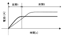
図9に、駆動モータ603が駆動する際のモータ電流波形の一例を示す。なお、図中の破線のグラフは、トナーが500[g]入ったトナーボトル33を駆動モータ603の駆動により回転させた際のモータ電流値の時間推移を示している。また、図中の実線のグラフは、トナーが70[g]入ったトナーボトル33を駆動モータ603の駆動により回転させた際のモータ電流値の時間推移を示している。図9に示すように、駆動モータ603の駆動始まりモータ電流値が上がっていく区間1と、モータ電流値が定常状態になる区間2とがある。駆動モータ603のモータ電流値は、駆動モータ603が駆動する際の負荷トルクに応じて変動するように設定されているため、駆動モータ603のモータ電流値を測定することで、駆動モータ603のトルクを類推することができる。また、例えば、トナーボトル33に入っているトナーの量が少ない(負荷トルクが小さい)と、前記区間1における電流値の立ち上がりが早くなり、前記区間2における定常状態のモータ電流値が低くなるといった特徴がある。   FIG. 9 shows an example of a motor current waveform when the drive motor 603 is driven. The broken line graph in the figure shows the time transition of the motor current value when the toner bottle 33 containing 500 [g] of toner is rotated by driving the drive motor 603. Further, the solid line graph in the figure shows the time transition of the motor current value when the toner bottle 33 containing 70 [g] of toner is rotated by driving the drive motor 603. As shown in FIG. 9, there are a section 1 in which the drive motor 603 starts driving and the motor current value increases, and a section 2 in which the motor current value is in a steady state. Since the motor current value of the drive motor 603 is set so as to vary according to the load torque when the drive motor 603 is driven, the torque of the drive motor 603 is measured by measuring the motor current value of the drive motor 603. Can be analogized. Further, for example, if the amount of toner contained in the toner bottle 33 is small (load torque is small), the current value rises quickly in the section 1 and the steady-state motor current value in the section 2 decreases. There are features.

ここで、図9からも明らかなように、前記区間1におけるモータ電流値の立ち上がりの早さや、前記区間2におけるモータ電流値の大きさでも、トナーボトル33内のトナー量を検知することが可能である。しかしながら、駆動モータ603自体の発熱や駆動モータ603の固体差により、前記区間1におけるモータ電流値の立ち上がりの早さ(立ち上げ時間)や、前記区間2における安定状態のモータ電流値の絶対値が、ばらついてしまう。具体的には、同じ重さのトナーボトル33を回転させる場合でも、駆動モータ603の温度が低い場合と、駆動モータ603の温度が高い場合では、駆動モータ内部のコイル抵抗が変わる。そのため、駆動モータ603を回転させるのに必要な電流値がかわってしまう。これにより、同じ重さのトナーボトル33を回転させるにも、必要なモータ電流値がかわってしまい、トナー量の検知誤差が大きくなるといった不具合が発生する。なお、駆動モータ603の温度が低くなるのは、使用環境が低い場合や、駆動モータ603の連続回転時間が短く駆動モータ603自体の発熱が低い場合などある。逆に、駆動モータ603の温度が高くなるのは、使用環境が高い場合や、駆動モータ603の連続回転時間が長く駆動モータ603自体の発熱が高い場合などである。   Here, as apparent from FIG. 9, the toner amount in the toner bottle 33 can be detected based on the speed of rise of the motor current value in the section 1 and the magnitude of the motor current value in the section 2. It is. However, due to the heat generation of the drive motor 603 itself and the individual difference of the drive motor 603, the speed of rise of the motor current value (rise time) in the section 1 and the absolute value of the stable motor current value in the section 2 are , Will vary. Specifically, even when the toner bottles 33 having the same weight are rotated, the coil resistance inside the drive motor changes when the temperature of the drive motor 603 is low and when the temperature of the drive motor 603 is high. Therefore, the current value necessary for rotating the drive motor 603 is changed. As a result, even when the toner bottle 33 having the same weight is rotated, a necessary motor current value is changed, and a problem that a detection error of the toner amount becomes large occurs. Note that the temperature of the drive motor 603 decreases when the usage environment is low or when the continuous rotation time of the drive motor 603 is short and the heat generation of the drive motor 603 itself is low. Conversely, the temperature of the drive motor 603 increases when the usage environment is high or when the continuous rotation time of the drive motor 603 is long and the heat generation of the drive motor 603 itself is high.

図10は、トナーボトル33を回転させる際のモータ電流波形の一例を示したグラフである。図1は、図10に示すグラフの四角で囲った範囲におけるモータ電流波形の拡大図である。本構成例に係るトナー補給装置60では、定常状態に達したモータ電流値の最大値と最小値との変動幅を測定し、トナーボトル33内のトナー量を判断する。そのため、トナーボトル33自体の相対的なモータ電流値の変動を測定するため、駆動モータ603の特性変動が起きてもトナー量の検知誤差を最低限に抑えることができる。   FIG. 10 is a graph showing an example of a motor current waveform when the toner bottle 33 is rotated. FIG. 1 is an enlarged view of a motor current waveform in a range surrounded by a square in the graph shown in FIG. In the toner replenishing device 60 according to this configuration example, the fluctuation range between the maximum value and the minimum value of the motor current value that has reached the steady state is measured, and the amount of toner in the toner bottle 33 is determined. For this reason, since the fluctuation of the relative motor current value of the toner bottle 33 itself is measured, even if the characteristic fluctuation of the drive motor 603 occurs, the detection error of the toner amount can be minimized.

図10に示すように、モータ電流波形が定常状態の中でも、図1に示すようにトナーボトル一回転周期でモータ電流値に変動が生じる。この変動は、トナーボトル33を回転させた際のトナーボトル33内におけるトナーの位置の偏りによって発生する。具体的には、図11に示すように、トナーボトル無回転時は、トナーボトル33内のトナーの粉面は画像形成装置の設置面に対してほぼ平行になっている。この状態から駆動モータ603により駆動をかけると、トナーボトル33の内周面とトナーとの摩擦から、図12に示すように、トナーボトル回転方向にトナーが持ち上がり、前記設置面に対してトナーの粉面が傾いた状態となる。その後、前記設置面に対してトナーの粉面がある角度以上になると、図11に示すようなトナーの粉面が前記設置面に対してほぼ平行となる状態に戻る。このように、トナーボトル33の回転に伴って、トナーボトル33の内周面とトナーとの摩擦によりトナーボトル33内におけるトナーの位置に偏りが生じることで、トナーボトル一回転周期でモータ電流値(駆動モータ603の負荷トルク)の変動が生じる。   As shown in FIG. 10, even when the motor current waveform is in a steady state, the motor current value fluctuates in one rotation cycle of the toner bottle as shown in FIG. This variation occurs due to the deviation of the toner position in the toner bottle 33 when the toner bottle 33 is rotated. Specifically, as shown in FIG. 11, when the toner bottle is not rotating, the toner powder surface in the toner bottle 33 is substantially parallel to the installation surface of the image forming apparatus. When the drive motor 603 is driven from this state, the toner rises in the toner bottle rotation direction due to friction between the inner peripheral surface of the toner bottle 33 and the toner, as shown in FIG. The powder surface is tilted. Thereafter, when the toner powder surface is at a certain angle or more with respect to the installation surface, the toner powder surface returns to a state almost parallel to the installation surface as shown in FIG. As described above, as the toner bottle 33 rotates, the toner position in the toner bottle 33 is biased due to friction between the inner peripheral surface of the toner bottle 33 and the toner. Variation in (load torque of the drive motor 603) occurs.

また、前記定常状態におけるモータ電流値の最大値と最小値との変動幅は、トナーボトル33内のトナー量に依存している。すなわち、トナーボトル33内のトナー量が少ない場合におけるモータ電流値の変動幅Δtは、トナー量が多い場合におけるモータ電流値の変動幅Δsよりも小さくなる。よって、モータ電流値の変動幅が予め設定された閾値よりも小さくなったときに、トナーボトル33内のトナー量が少なくなった旨を表示パネル111などに表示してユーザーに報知する。また、モータ電流値の変動幅が0になったときは、トナーボトル33内にトナーが無い旨を表示パネル111などに表示してユーザーに報知する。これにより、駆動モータ603自体の発熱や環境による駆動モータ603のモータ電流値の変動が発生した場合や、駆動モータ603の固体差によるモータ電流値の変動が発生した場合でも、トナーボトル33内のトナー量を精度良く検知することができる。   The fluctuation range between the maximum value and the minimum value of the motor current value in the steady state depends on the amount of toner in the toner bottle 33. That is, the fluctuation range Δt of the motor current value when the toner amount in the toner bottle 33 is small is smaller than the fluctuation range Δs of the motor current value when the toner amount is large. Therefore, when the fluctuation range of the motor current value becomes smaller than a preset threshold value, the fact that the amount of toner in the toner bottle 33 has decreased is displayed on the display panel 111 or the like to notify the user. Further, when the fluctuation range of the motor current value becomes 0, the fact that there is no toner in the toner bottle 33 is displayed on the display panel 111 or the like to notify the user. As a result, even when a change in the motor current value of the drive motor 603 due to the heat generation of the drive motor 603 itself or the environment occurs, or even when a change in the motor current value due to the individual difference of the drive motor 603 occurs, The toner amount can be accurately detected.

[構成例2]
トナーボトル33を回転し続けることで、トナーの流動化が起り、トナーが液体のようになってしまい、トナーボトル33の回転に伴ってトナーが持ち上がり難くなる場合がある。この場合、トナーボトル33内に多量のトナーがあっても、駆動モータ603の負荷トルクの変動(モータ電流値の変動)が発生し難く、負荷トルクの変動幅(モータ電流値の変動幅)を用いてトナーボトル33内のトナー量を検知するのが困難になるおそれがある。
[Configuration example 2]
By continuing to rotate the toner bottle 33, the fluidization of the toner occurs, the toner becomes like a liquid, and it may be difficult to lift the toner as the toner bottle 33 rotates. In this case, even if there is a large amount of toner in the toner bottle 33, fluctuations in the load torque of the drive motor 603 (fluctuations in the motor current value) hardly occur, and the fluctuation range of the load torque (variation width of the motor current value) is reduced. It may be difficult to detect the amount of toner in the toner bottle 33.

図13は、内周面に板状突起部35a,35bを設けたトナーボトル33の軸線方向と直交する方向で切断した断面図である。図14は、内周面に板状突起部35a,35bを設けたトナーボトル33の軸線方向で切断した断面図である。本構成例においては、図13に示すように、トナーボトル33の内周面から突出するとともにトナーボトル軸線方向にわたって延在し、トナーボトル回転方向で対向する二つの板状突起部35a,35bを設けている。また、図14に示すように、板状突起部35a,35bの前記内周面からの突出高さは、トナーボトル軸線方向にわたって同じであり、前記内周面に形成された螺旋状突起302による前記内周面の凹凸にならって、板状突起部35a,35bも凹凸している。これにより、トナーボトル33の内周面に板状突起部35a,35bを設けても、螺旋状突起302によるトナーボトル33の軸線方向後端側から先端側へのトナー搬送性を維持することができる。   FIG. 13 is a cross-sectional view taken along a direction orthogonal to the axial direction of the toner bottle 33 provided with plate-like protrusions 35a and 35b on the inner peripheral surface. FIG. 14 is a cross-sectional view taken along the axial direction of the toner bottle 33 provided with plate-like protrusions 35a and 35b on the inner peripheral surface. In this configuration example, as shown in FIG. 13, two plate-like protrusions 35 a and 35 b that protrude from the inner peripheral surface of the toner bottle 33 and extend in the toner bottle axial direction and face each other in the toner bottle rotation direction are provided. Provided. Further, as shown in FIG. 14, the protruding heights of the plate-like projections 35a and 35b from the inner peripheral surface are the same in the toner bottle axial direction, and are due to the helical projections 302 formed on the inner peripheral surface. The plate-like protrusions 35a and 35b are also uneven according to the unevenness of the inner peripheral surface. Thus, even if the plate-like protrusions 35a and 35b are provided on the inner peripheral surface of the toner bottle 33, the toner conveyance performance from the rear end side in the axial direction of the toner bottle 33 to the front end side by the spiral protrusion 302 can be maintained. it can.

そして、トナーボトル33の回転に伴って、トナーボトル33内のトナーを板状突起部35a,35bにより強制的に持ち上げ、ある所で板状突起部35a,35bからトナーが落下することで、トナーボトル33内におけるトナーの偏りを擬似的に発生させる。これにより、トナーボトル33内のトナーが液体のように流動化しても、トナーボトル一回転周期における駆動モータ603のモータ電流値の変動幅から、トナーボトル33内のトナー量を検知することができる。   Then, as the toner bottle 33 rotates, the toner in the toner bottle 33 is forcibly lifted by the plate-like protrusions 35a and 35b, and the toner falls from the plate-like protrusions 35a and 35b at a certain place, thereby The toner bias in the bottle 33 is generated in a pseudo manner. Thereby, even if the toner in the toner bottle 33 is fluidized like a liquid, the amount of toner in the toner bottle 33 can be detected from the fluctuation range of the motor current value of the drive motor 603 in one rotation period of the toner bottle. .

なお、トナーボトル33の内周面に板状突起部を1個設けた場合は、トナーの粉面位置と前記突起の位置とが、ちょうど同じときに、トナーボトル一回転周期の間で駆動モータ603の負荷トルク変動が発生せず、トナー量の検知精度が低下するおそれがある。そのため、トナーボトル33の内周面のトナーボトル回転方向で異なる位置に板状突起部を2個以上設けることで、前述のようなトナー量の検知不良が発生するのを抑制することができる。   In the case where one plate-like protrusion is provided on the inner peripheral surface of the toner bottle 33, when the toner powder surface position is exactly the same as the position of the protrusion, the driving motor is rotated during one rotation period of the toner bottle. There is a possibility that the load torque fluctuation of 603 does not occur and the toner amount detection accuracy is lowered. Therefore, by providing two or more plate-like protrusions at different positions on the inner peripheral surface of the toner bottle 33 in the toner bottle rotation direction, it is possible to suppress the occurrence of the toner amount detection failure as described above.

[実施形態2]
本発明を適用した画像形成装置の他の実施形態について説明する。ここで、実施形態2に係るプリンタの基本的な構成は、実施形態1に係るプリンタの構成と同様なので、その説明は省略する。
[Embodiment 2]
Another embodiment of the image forming apparatus to which the present invention is applied will be described. Here, the basic configuration of the printer according to the second embodiment is the same as the configuration of the printer according to the first embodiment, and a description thereof will be omitted.

図15は、実施形態2に係るトナー補給装置60の模式図である。図16(a)は、トナーボトル33を軸線方向後端側から見た図である。図16(b)は、トナーボトル33が持ち上げられた状態を示すトナーボトル33を軸線方向後端側から見た図。図16(c)は、トナーボトル33が落下した状態を示すトナーボトル33を軸線方向後端側から見た図。トナーボトル33は、トナー補給装置60に設けられた樹脂材料からなる2つのガイド部74a,74bに支持されており、ガイド部74a,74bに外周面がガイドされながらトナーボトル33が回転する。また、図15や図16に示すように、トナーボトル33の外周面におけるガイド部74a,74bに対応する位置に、断面が三角形の三角突起部36が設けられている。この三角突起部36は、頂点36cを挟んで、トナーボトル回転方向下流側に位置する下流側傾斜面36aと、トナーボトル回転方向上流側に位置する上流側傾斜面36bとを有している。下流側傾斜面36aは、トナーボトル外周面に対してトナーボトル回転方向下流側から上流側に向かうに連れて高さが高くなるように傾斜している。上流側傾斜面36bは、トナーボトル外周面に対してトナーボトル回転方向下流側から上流側に向かうに連れて高さが低くなるように傾斜している。   FIG. 15 is a schematic diagram of a toner supply device 60 according to the second embodiment. FIG. 16A is a diagram of the toner bottle 33 viewed from the rear end side in the axial direction. FIG. 16B is a diagram of the toner bottle 33 showing a state in which the toner bottle 33 is lifted, as viewed from the rear end side in the axial direction. FIG. 16C is a diagram illustrating the toner bottle 33 in a state where the toner bottle 33 has been dropped as viewed from the rear end side in the axial direction. The toner bottle 33 is supported by two guide portions 74a and 74b made of a resin material provided in the toner replenishing device 60, and the toner bottle 33 rotates while the outer peripheral surface is guided by the guide portions 74a and 74b. As shown in FIGS. 15 and 16, a triangular protrusion 36 having a triangular cross section is provided at a position corresponding to the guide portions 74 a and 74 b on the outer peripheral surface of the toner bottle 33. The triangular protrusion 36 has a downstream inclined surface 36a located on the downstream side in the toner bottle rotation direction and an upstream inclined surface 36b located on the upstream side in the toner bottle rotation direction with the apex 36c interposed therebetween. The downstream inclined surface 36a is inclined with respect to the outer peripheral surface of the toner bottle such that the height increases from the downstream side in the toner bottle rotation direction toward the upstream side. The upstream inclined surface 36b is inclined with respect to the outer peripheral surface of the toner bottle so that the height decreases from the downstream side in the toner bottle rotation direction toward the upstream side.

そして、例えば、図16(a)に示す位置からトナーボトル33が回転し、三角突起部36の下流側傾斜面36aがガイド部74bを通過するときには、図16(b)に示すように、トナーボトル33が三角突起部36の高さ分だけ持ち上がる。その後、図16(c)に示すように、三角突起部36の下流側傾斜面36aがガイド部74bを通過し終え頂点36cがガイド部74bを抜けると、持ち上げられていたトナーボトル33が落下し、外周面がガイド部74a,74bで支持される元の位置に戻る。この際、トナーボトル33とガイド部74a,74bとが衝突して、トナーボトル33に振動が与えられる。そして、さらにトナーボトル33が回転し、三角突起部36の下流側傾斜面36aがガイド部74aを通過するときに、三角突起部36の高さ分だけトナーボトル33が持ち上がる。その後、三角突起部36の下流側傾斜面36aがガイド部74bを通過し終え頂点36cがガイド部74aを抜けると、持ち上げられていたトナーボトル33が落下し、外周面がガイド部74a,74bで支持される元の位置に戻る。この際、トナーボトル33とガイド部74a,74bとが衝突して、トナーボトル33に振動が与えられる。   For example, when the toner bottle 33 rotates from the position shown in FIG. 16A and the downstream inclined surface 36a of the triangular protrusion 36 passes through the guide portion 74b, as shown in FIG. The bottle 33 is lifted by the height of the triangular protrusion 36. Thereafter, as shown in FIG. 16C, when the downstream inclined surface 36a of the triangular protrusion 36 has passed through the guide portion 74b and the apex 36c has passed through the guide portion 74b, the toner bottle 33 that has been lifted falls. The outer peripheral surface returns to the original position supported by the guide portions 74a and 74b. At this time, the toner bottle 33 and the guide portions 74a and 74b collide, and the toner bottle 33 is vibrated. When the toner bottle 33 is further rotated and the downstream inclined surface 36a of the triangular protrusion 36 passes through the guide portion 74a, the toner bottle 33 is lifted by the height of the triangular protrusion 36. Thereafter, when the downstream inclined surface 36a of the triangular protrusion 36 finishes passing through the guide portion 74b and the apex 36c passes through the guide portion 74a, the toner bottle 33 that has been lifted falls, and the outer peripheral surface is formed by the guide portions 74a and 74b. Return to the original supported position. At this time, the toner bottle 33 and the guide portions 74a and 74b collide, and the toner bottle 33 is vibrated.

このような三角突起部36とガイド部74a,74bとによるトナーボトル33の持ち上げと落下の動作は、トナーボトル33の内壁に付着したトナーを振動によって振るい落とし、トナーボトル33内のトナーを無駄無く使い切るために行っている。   The operation of lifting and dropping the toner bottle 33 by the triangular protrusion 36 and the guide portions 74a and 74b shakes off the toner adhering to the inner wall of the toner bottle 33 by vibration, so that the toner in the toner bottle 33 is not wasted. I'm going to run out.

図17は、トナーボトル33を回転させる際のモータ電流波形の一例を示したグラフである。トナーボトル33の回転動作で駆動モータ603のモータ電流値は、図17に示すグラフのようになる。本実施形態で使用する駆動モータ603は、DCブラシモータであって駆動トルクとモータ電流値との間に比例関係がある。したがって、モータ電流値を計測すれば駆動モータ603の駆動トルクを把握することができる。   FIG. 17 is a graph showing an example of a motor current waveform when the toner bottle 33 is rotated. The motor current value of the drive motor 603 by the rotation operation of the toner bottle 33 is as shown in the graph of FIG. The drive motor 603 used in this embodiment is a DC brush motor, and there is a proportional relationship between the drive torque and the motor current value. Therefore, if the motor current value is measured, the driving torque of the driving motor 603 can be grasped.

図18に、図17に示すグラフの四角で囲った範囲Aにおける、三角突起部36とガイド部74a,74bとによりトナーボトル33が振動したときのモータ電流波形の拡大図を示す。トナーボトル33の回転に伴って、ガイド部74a,74bを三角突起部36が通過し、持ち上げられたトナーボトル33が落下したときの振動により、駆動モータ603のモータ電流値は、図18に示すように変動する。このときのモータ電流波形の最大変動幅をSとすると、トナーボトル33内のトナー量が多いときは、トナー量が少ないときに比べて最大変動幅Sは大きくなる。また、トナーボトル33内のトナー量が多いときのほうが、トナー量が少ないときに比べてモータ電流波形の振幅変動の収束も速い。   FIG. 18 shows an enlarged view of the motor current waveform when the toner bottle 33 vibrates due to the triangular protrusion 36 and the guide portions 74a and 74b in the range A enclosed by the square of the graph shown in FIG. As the toner bottle 33 rotates, the triangular protrusion 36 passes through the guide portions 74a and 74b, and the motor current value of the drive motor 603 is shown in FIG. Fluctuate as follows. If the maximum fluctuation range of the motor current waveform at this time is S, the maximum fluctuation range S is larger when the toner amount in the toner bottle 33 is large than when the toner amount is small. Further, when the amount of toner in the toner bottle 33 is large, the convergence of the amplitude fluctuation of the motor current waveform is faster than when the amount of toner is small.

そして、本願発明者らが鋭意研究を重ねた結果、前記最大変動幅Sは、トナーボトル33内のトナー量により変化し、図19に示すように、トナーボトル33内のトナー量(トナー重量)と、モータ電流波形の最大変動幅Sとは、比例関係になっていることが分かった。そのため、トナーボトル33内のトナー量(トナー重量M)とモータ電流値の最大変動幅Sとの関係を示す直線の傾きaと、トナー満充填時のモータ電流値の最大変動幅fと、トナーボトル33が空のときのモータ電流値の変動幅eを予め求めておく。これにより、モータ電流値の最大変動幅Sの値が分かれば、そのときのトナーボトル33内におけるトナー量を、図19に示す直線のグラフを表す式(S=aM+e)から求めることができる。なお、モータ電流値の変動幅Sは小さい値のため、トナー量検知の際に、トナーボトル二回転から五回転分の変動幅Sの平均値を用いることで、トナー量の検知誤差が少なくなり好ましい。   Then, as a result of extensive studies by the inventors of the present application, the maximum fluctuation range S changes depending on the amount of toner in the toner bottle 33, and as shown in FIG. 19, the amount of toner (toner weight) in the toner bottle 33 is changed. It has been found that the maximum fluctuation width S of the motor current waveform has a proportional relationship. Therefore, the slope a of the straight line indicating the relationship between the toner amount (toner weight M) in the toner bottle 33 and the maximum fluctuation range S of the motor current value, the maximum fluctuation range f of the motor current value when the toner is fully filled, and the toner A fluctuation range e of the motor current value when the bottle 33 is empty is obtained in advance. Thus, if the value of the maximum fluctuation range S of the motor current value is known, the toner amount in the toner bottle 33 at that time can be obtained from an equation (S = aM + e) representing a straight line graph shown in FIG. Since the fluctuation range S of the motor current value is small, the toner amount detection error is reduced by using the average value of the fluctuation range S for two to five rotations of the toner bottle when detecting the toner amount. preferable.

また、駆動モータ603の駆動トルク(モータ電流値)は、駆動モータ603自身の経時劣化や、トナーボトル33に駆動を伝達する駆動装置等の劣化等により、トナーボトル33内のトナー量が同じでも変化する可能性がある。そのため、トナー補給装置60に新しいトナーボトル33がセットされるごとに、トナー満載時における変動幅Sの初期値(図19における値f)を更新することで、トナー量の測定精度を維持することができる。   Further, the drive torque (motor current value) of the drive motor 603 may be the same even if the amount of toner in the toner bottle 33 is the same due to deterioration of the drive motor 603 itself over time, deterioration of the drive device that transmits drive to the toner bottle 33, or the like. It can change. Therefore, each time a new toner bottle 33 is set in the toner replenishing device 60, the initial value of the fluctuation range S when the toner is fully loaded (value f in FIG. 19) is updated to maintain the toner amount measurement accuracy. Can do.

以上に説明したものは一例であり、次の態様毎に特有の効果を奏する。
(態様A)
トナーなどの粉体を収納するトナーボトル33などの粉体収納容器と、前記粉体収納容器を回転させる駆動モータ603などの駆動モータとを備え、前記粉体収納容器を回転させて該粉体収納容器内の粉体を排出し現像装置7などの補給先に補給するトナー補給装置60などの粉体補給装置において、粉体収納容器の一回転周期における駆動モータの負荷トルクに関する値の変動幅を取得する制御部100などの変動幅取得手段と、前記変動幅に基づいて、前記粉体収納容器内の粉体量を検知する制御部100などの粉体量検知手段とを有する。
本願発明者らが鋭意研究を重ねた結果、粉体収納容器の一回転周期で駆動モータの負荷トルクに変動が生じ、その変動の幅が、粉体収納容器内の粉体量が多いほど大きくなり、粉体量が少ないほど小さくなることがわかった。そして、粉体収納容器内の粉体量と、前記負荷トルクの変動幅とは、比例関係にあることを見出した。
(態様A)においては、変動幅取得手段が取得した、粉体収納容器の一回転周期における駆動モータの負荷トルクに関する値の変動幅に基づいて、粉体量検知手段により粉体収納容器内の粉体量を検知することができる。これにより、粉体収納容器内の粉体量を検知するために圧電素子などからなる粉体検知センサを設ける必要がないので、その分、低コスト化を図ることが可能となる。よって、低コスト化を図りつつ、粉体収納容器内の粉体量を検知することができる。
(態様B)
(態様A)において、前記変動幅取得手段は、前記駆動モータの回転速度が所定速度に達してから前記変動幅を取得する。これによれば、上記実施形態について説明したように、粉体量の検知精度を高めることができる。
(態様C)
(態様A)または(態様B)において、前記粉体収納容器の一回転周期における前記負荷トルクに関する値の最大値と最小値との差を前記変動幅とする。これによれば、上記実施形態について説明したように、駆動モータの特性変動が起きても検知誤差を最低限に抑えることができる。
(態様D)
(態様A)乃至(態様C)のいずれかにおいて、前記粉体収納容器の内周面に該内周面から突出した突起部を設けた。これによれば、上記実施形態について説明したように、粉体収納容器内の粉体が液体のように流動化しても、前記変動幅に基づいて粉体量を検知することができる。
(態様E)
(態様D)において、前記内周面の粉体収納容器回転方向で異なる位置に、前記突起部を2つ以上設けた。これによれば、上記実施形態について説明したように、粉体量の検知不良が発生するのを抑制することができる。
(態様F)
(態様A)乃至(態様E)のいずれかにおいて、前記粉体量検知手段の検知結果に基づいて、前記粉体収納容器の中に粉体が無い場合に、該粉体収納容器の交換を促す表示を行う表示手段を有する。これによれば、上記実施形態について説明したように、ユーザーに粉体収納容器の交換を促すことができる。
(態様G)
(態様A)乃至(態様E)のいずれかにおいて、前記粉体量検知手段の検知結果に基づいて、前記粉体収納容器の中の粉体が所定量よりも少ない場合に、該粉体収納容器の交換を促す表示を行う表示手段を有する。これによれば、上記実施形態について説明したように、ユーザーに粉体収納容器の交換を促すことができる。
(態様H)
(態様A)乃至(態様G)のいずれかにおいて、前記粉体収納容器の回転中に該粉体収納容器に衝撃を与えて振動させる振動手段を有しており、前記振動手段によって前記粉体収納容器を振動させたときの前記変動幅に基づいて、前記粉体量検知手段が前記粉体収納容器内の粉体量を検知する。これによれば、上記実施形態について説明したように、粉体量を精度良く検知することができる。
(態様I)
(態様H)において、前記振動手段は、前記粉体収納容器の外壁面と接触して該粉体収納容器の回転をガイドしながら該粉体収納容器を支持する支持部材と、前記粉体収納容器の前記外壁面における前記支持部材に対応する位置に設けられた突起部とで構成される。これによれば、上記実施形態について説明したように、粉体収納容器の内壁に付着した粉体を振動によって振るい落とし、粉体収納容器内の粉体を無駄無く使い切るための構成を、粉体量の検知に流用することができる。
(態様J)
(態様A)乃至(態様I)のいずれかにおいて、新しい粉体収納容器がセットとされたときに、前記粉体量検知手段が粉体量の検知に用いる前記変動幅の初期値を更新する。これによれば、上記実施形態について説明したように、粉体量の検知精度を維持することができる。
(態様K)
(態様J)において、前記初期値は、前記粉体収納容器内に粉体が満杯に充填された状態における前記変動幅である。これによれば、上記実施形態について説明したように、粉体量の検知精度を維持することができる。
(態様L)
(態様A)乃至(態様K)のいずれかにおいて、前記変動幅取得手段が取得した複数の前記変動幅の平均値を、前記粉体量検知手段による粉体量検知に用いる。これによれば、上記実施形態について説明したように、粉体量の検知誤差を少なくすることができる。
(態様M)
(態様A)乃至(態様L)のいずれかにおいて、前記駆動モータに電流を供給する電流供給手段を有しており、前記負荷トルクに関する情報がモータ電流値である。これによれば、上記実施形態について説明したように、粉体収納容器の一回転周期における駆動モーのモータ電流値の変動幅から、粉体収納容器内の粉体量を検知することができる。
(態様N)
感光体3などの像担持体と、現像剤を用いて像担持体上の潜像を現像する現像装置7などの現像手段と、前記現像手段で使用される現像剤を収容するトナーボトル33などの現像剤収納容器と、前記現像剤収納容器内の現像剤を前記現像手段に補給するトナー補給装置60などの現像剤補給手段とを備えた画像形成装置において、前記現像剤補給手段として、(態様A)乃至(態様M)のいずれか一記載の粉体補給装置を用いる。これによれば、上記実施形態について説明したように、コストを抑えつつ、粉体収納容器内の粉体量を検知することができる。
What was demonstrated above is an example, and there exists an effect peculiar for every following aspect.
(Aspect A)
A powder storage container such as a toner bottle 33 for storing powder such as toner; and a drive motor such as a drive motor 603 for rotating the powder storage container. The powder storage container is rotated to rotate the powder. In a powder replenishing device such as a toner replenishing device 60 that discharges powder in the storage container and replenishes it to a replenishment destination such as the developing device 7, the fluctuation range of the value related to the load torque of the drive motor in one rotation cycle of the powder container Fluctuation range acquisition means, such as the control unit 100, and a powder amount detection unit, such as the control unit 100, that detects the amount of powder in the powder container based on the fluctuation range.
As a result of extensive research by the inventors of the present application, the load torque of the drive motor fluctuates in one rotation cycle of the powder container, and the width of the fluctuation increases as the amount of powder in the powder container increases. It was found that the smaller the amount of powder, the smaller. The inventors have found that the amount of powder in the powder container and the fluctuation range of the load torque are in a proportional relationship.
In (Aspect A), based on the fluctuation range of the value related to the load torque of the drive motor in one rotation cycle of the powder storage container acquired by the fluctuation width acquisition means, the powder amount detection means The amount of powder can be detected. Accordingly, it is not necessary to provide a powder detection sensor made of a piezoelectric element or the like in order to detect the amount of powder in the powder container, so that the cost can be reduced accordingly. Therefore, it is possible to detect the amount of powder in the powder container while reducing costs.
(Aspect B)
In (Aspect A), the fluctuation range acquisition unit acquires the fluctuation range after the rotational speed of the drive motor reaches a predetermined speed. According to this, as described in the above embodiment, the detection accuracy of the powder amount can be increased.
(Aspect C)
In (Aspect A) or (Aspect B), the difference between the maximum value and the minimum value of the load torque in one rotation period of the powder container is defined as the fluctuation range. According to this, as described in the above embodiment, the detection error can be suppressed to the minimum even if the characteristic variation of the drive motor occurs.
(Aspect D)
In any one of (Aspect A) to (Aspect C), a protrusion protruding from the inner peripheral surface is provided on the inner peripheral surface of the powder container. According to this, as described in the above embodiment, even if the powder in the powder container is fluidized like a liquid, the amount of powder can be detected based on the fluctuation range.
(Aspect E)
In (Aspect D), two or more protrusions are provided at different positions in the rotational direction of the powder container on the inner peripheral surface. According to this, as described in the above embodiment, it is possible to suppress the occurrence of a powder amount detection failure.
(Aspect F)
In any one of (Aspect A) to (Aspect E), when there is no powder in the powder storage container, the powder storage container is replaced based on the detection result of the powder amount detection means. It has a display means for performing a prompting display. According to this, as described in the above embodiment, it is possible to prompt the user to replace the powder container.
(Aspect G)
In any one of (Aspect A) to (Aspect E), when the amount of powder in the powder storage container is less than a predetermined amount based on the detection result of the powder amount detection means, the powder storage It has a display means which performs the display which prompts replacement | exchange of a container. According to this, as described in the above embodiment, it is possible to prompt the user to replace the powder container.
(Aspect H)
In any one of (Aspect A) to (Aspect G), the powder storage container is provided with vibration means that vibrates by applying an impact to the powder storage container during the rotation of the powder storage container. Based on the fluctuation range when the storage container is vibrated, the powder amount detection means detects the amount of powder in the powder storage container. According to this, as described in the above embodiment, the amount of powder can be detected with high accuracy.
(Aspect I)
In (Aspect H), the vibrating means contacts the outer wall surface of the powder container and supports the powder container while guiding the rotation of the powder container, and the powder container And a protrusion provided at a position corresponding to the support member on the outer wall surface of the container. According to this, as described in the above embodiment, the powder attached to the inner wall of the powder storage container is shaken off by vibration, and the configuration for using up the powder in the powder storage container without waste is used. It can be used to detect the amount.
(Aspect J)
In any one of (Aspect A) to (Aspect I), when a new powder container is set, the powder amount detection means updates the initial value of the fluctuation range used for detecting the powder amount. . According to this, the powder amount detection accuracy can be maintained as described in the above embodiment.
(Aspect K)
In (Aspect J), the initial value is the fluctuation range in a state where the powder container is filled with powder. According to this, the powder amount detection accuracy can be maintained as described in the above embodiment.
(Aspect L)
In any one of (Aspect A) to (Aspect K), an average value of the plurality of fluctuation ranges acquired by the fluctuation range acquisition unit is used for powder amount detection by the powder amount detection unit. According to this, as described in the above embodiment, the powder amount detection error can be reduced.
(Aspect M)
In any one of (Aspect A) to (Aspect L), there is provided current supply means for supplying a current to the drive motor, and the information on the load torque is a motor current value. According to this, as described in the above embodiment, the amount of powder in the powder container can be detected from the fluctuation range of the motor current value of the drive motor in one rotation cycle of the powder container.
(Aspect N)
An image carrier such as the photoreceptor 3, a developing unit such as a developing device 7 that develops a latent image on the image carrier using a developer, a toner bottle 33 that contains a developer used in the developing unit, and the like In the image forming apparatus comprising the developer storage container and a developer supply means such as a toner supply device 60 for supplying the developer in the developer storage container to the developing means, the developer supply means is ( The powder supply device according to any one of Aspects A) to (Aspect M) is used. According to this, as explained about the above-mentioned embodiment, it is possible to detect the amount of powder in the powder container while suppressing cost.

1 プロセスユニット
2 感光体ユニット
3 感光体
4 ドラムクリーニング装置
5 帯電装置
6 帯電ローラ
7 現像装置
8 第一現像剤搬送スクリュウ
9 第一剤収容室
10 トナー濃度センサ
11 第二現像剤搬送スクリュウ
12 現像ロール
13 ドクターブレード
14 第二剤収容室
15 現像スリーブ
16 マグネットローラ
17 トナー補給口
18 連通口
19 連通口
20 光書込ユニット
21 ポリゴンミラー
22 第一給紙カセット
22a 第一給紙ローラ
23 第二給紙カセット
23a 第二給紙ローラ
24 給紙路
25 搬送ローラ対
26 レジストローラ対
32 トナー収容器
33 トナーボトル
34 容器先端カバー
34b 色非互換リブ
35a 板状突起部
35b 板状突起部
36 三角突起部
36a 下流側傾斜面
36b 上流側傾斜面
36c 頂点
40 転写ユニット
41 中間転写ベルト
45 一次転写ローラ
46 二次転写バックアップローラ
47 駆動ローラ
49 テンションローラ
50 二次転写ローラ
60 トナー補給装置
63 サブホッパ
64 トナー落下搬送路
70 収容器搭載部
71 挿入口形成部
72 容器受部
73 先端受部
74a ガイド部
74b ガイド部
80 定着装置
81 加圧加熱ローラ
82 定着ベルトユニット
83 加熱ローラ
84 定着ベルト
85 テンションローラ
86 駆動ローラ
87 排紙ローラ対
88 スタック部
100 制御部
101 CPU
102 RAM
103 ROM
111 表示パネル
120 電源部
180 駆動機構
181a 収容器側駆動機構部
181b サブホッパ側駆動機構部
301 容器回転ギヤ
302 螺旋状突起
303 把手部
304 汲み上げ部
305 先端開口形成部
330 ノズル受入部材
331 ノズル受入口
332 容器シャッタ部材
333 容器シール部材
335b シャッタ支持開口部
336 容器シャッタバネ
339 ロック用開口
601 容器駆動出力ギヤ
602 フレーム
603 駆動モータ
603a ウォームギヤ
604 駆動伝達ギヤ
605 搬送スクリュウギヤ
607 ノズルホルダ
608 セットカバー
609 容器ロック部材
610 ノズル開口部
611 搬送ノズル
611a ノズル先端部
612 ノズルシャッタ部材
612a ノズルシャッタ鍔部
612b ノズルシャッタ筒状部
613 ノズルシャッタバネ
614 搬送スクリュウ
615 容器セット部
700 IDチップ
DESCRIPTION OF SYMBOLS 1 Process unit 2 Photoconductor unit 3 Photoconductor 4 Drum cleaning apparatus 5 Charging apparatus 6 Charging roller 7 Developing apparatus 8 First developer conveyance screw 9 First agent storage chamber 10 Toner density sensor 11 Second developer conveyance screw 12 Developing roll 13 Doctor blade 14 Second agent storage chamber 15 Developing sleeve 16 Magnet roller 17 Toner supply port 18 Communication port 19 Communication port 20 Optical writing unit 21 Polygon mirror 22 First paper feed cassette 22a First paper feed roller 23 Second paper feed Cassette 23a Second paper feed roller 24 Paper feed path 25 Transport roller pair 26 Registration roller pair 32 Toner container 33 Toner bottle 34 Container tip cover 34b Color incompatible rib 35a Plate-like projection 35b Plate-like projection 36 Triangular projection 36a Downstream slope 36b Upstream slope Surface 36c Vertex 40 Transfer unit 41 Intermediate transfer belt 45 Primary transfer roller 46 Secondary transfer backup roller 47 Drive roller 49 Tension roller 50 Secondary transfer roller 60 Toner replenishing device 63 Sub hopper 64 Toner drop conveyance path 70 Container mounting portion 71 Insert port Forming unit 72 container receiving unit 73 tip receiving unit 74a guide unit 74b guide unit 80 fixing device 81 pressure heating roller 82 fixing belt unit 83 heating roller 84 fixing belt 85 tension roller 86 driving roller 87 discharge roller pair 88 stack unit 100 control Unit 101 CPU
102 RAM
103 ROM
DESCRIPTION OF SYMBOLS 111 Display panel 120 Power supply part 180 Drive mechanism 181a Container side drive mechanism part 181b Sub hopper side drive mechanism part 301 Container rotation gear 302 Spiral protrusion 303 Handle part 304 Pumping part 305 Tip opening formation part 330 Nozzle receiving member 331 Nozzle inlet 332 Container shutter member 333 Container seal member 335b Shutter support opening 336 Container shutter spring 339 Lock opening 601 Container drive output gear 602 Frame 603 Drive motor 603a Worm gear 604 Drive transmission gear 605 Transport screw gear 607 Nozzle holder 608 Set cover 609 Container lock member 610 Nozzle opening 611 Conveying nozzle 611a Nozzle tip 612 Nozzle shutter member 612a Nozzle shutter collar 612b Nozzle shutter cylinder Part 613 nozzle shutter spring 614 screw conveyor 615 container holder 700 ID chip

特開2014−235339号公報JP 2014-235339 A

Claims (14)

粉体を収納する粉体収納容器と、
前記粉体収納容器を回転させる駆動モータとを備え、
前記粉体収納容器を回転させて該粉体収納容器内の粉体を排出し補給先に補給する粉体補給装置において、
前記粉体収納容器の一回転周期における前記駆動モータの負荷トルクに関する値の変動幅を取得する変動幅取得手段と、
前記変動幅に基づいて、前記粉体収納容器内の粉体量を検知する粉体量検知手段とを有することを特徴とする粉体補給装置。
A powder storage container for storing powder;
A drive motor for rotating the powder container,
In the powder replenishing device for rotating the powder container and discharging the powder in the powder container and replenishing the replenishment destination,
A fluctuation range obtaining means for obtaining a fluctuation range of a value related to a load torque of the drive motor in one rotation period of the powder container;
A powder replenishing device comprising powder amount detecting means for detecting the amount of powder in the powder container based on the fluctuation range.
請求項1に記載の粉体補給装置において、
前記変動幅取得手段は、前記駆動モータの回転速度が所定速度に達してから前記変動幅を取得することを特徴とする粉体補給装置。
The powder supply device according to claim 1,
The powder fluctuation supply device, wherein the fluctuation width acquisition means acquires the fluctuation width after the rotation speed of the drive motor reaches a predetermined speed.
請求項1または2に記載の粉体補給装置において、
前記粉体収納容器の一回転周期における前記負荷トルクに関する値の最大値と最小値との差を前記変動幅とすることを特徴とする粉体補給装置。
The powder supply device according to claim 1 or 2,
The powder replenishing apparatus characterized in that a difference between a maximum value and a minimum value of the load torque in one rotation cycle of the powder container is defined as the fluctuation range.
請求項1乃至3のいずれか一記載の粉体補給装置において、
前記粉体収納容器の内周面に該内周面から突出した突起部を設けたことを特徴とする粉体補給装置。
In the powder supply device according to any one of claims 1 to 3,
A powder replenishing device, wherein a protrusion protruding from the inner peripheral surface is provided on the inner peripheral surface of the powder container.
請求項4に記載の粉体補給装置において、
前記内周面の粉体収納容器回転方向で異なる位置に、前記突起部を2つ以上設けたことを特徴とする粉体補給装置。
The powder supply device according to claim 4, wherein
2. A powder replenishing device, wherein two or more of the protrusions are provided at different positions on the inner peripheral surface in the direction of rotation of the powder container.
請求項1乃至5のいずれか一記載の粉体補給装置において、
前記粉体量検知手段の検知結果に基づいて、前記粉体収納容器の中に粉体が無い場合に、該粉体収納容器の交換を促す表示を行う表示手段を有することを特徴とする粉体補給装置。
The powder supply device according to any one of claims 1 to 5,
A powder having display means for displaying a message prompting replacement of the powder container when there is no powder in the powder container based on a detection result of the powder amount detector. Body supply device.
請求項1乃至5のいずれか一記載の粉体補給装置において、
前記粉体量検知手段の検知結果に基づいて、前記粉体収納容器の中の粉体が所定量よりも少ない場合に、該粉体収納容器の交換を促す表示を行う表示手段を有することを特徴とする粉体補給装置。
The powder supply device according to any one of claims 1 to 5,
Based on the detection result of the powder amount detection means, there is provided display means for performing a display prompting replacement of the powder storage container when the powder in the powder storage container is less than a predetermined amount. A powder replenishing device.
請求項1乃至7のいずれか一記載の粉体補給装置において、
前記粉体収納容器の回転中に該粉体収納容器に衝撃を与えて振動させる振動手段を有しており、
前記振動手段によって前記粉体収納容器を振動させたときの前記変動幅に基づいて、前記粉体量検知手段が前記粉体収納容器内の粉体量を検知することを特徴とする粉体補給装置。
In the powder replenishing device according to any one of claims 1 to 7,
Having vibration means for applying an impact to the powder container during vibration of the powder container and vibrating the container;
Powder supply, wherein the powder amount detection means detects the amount of powder in the powder storage container based on the fluctuation range when the powder storage container is vibrated by the vibration means. apparatus.
請求項8に記載の粉体補給装置において、
前記振動手段は、前記粉体収納容器の外壁面と接触して該粉体収納容器の回転をガイドしながら該粉体収納容器を支持する支持部材と、前記粉体収納容器の前記外壁面における前記支持部材に対応する位置に設けられた突起部とで構成されることを特徴とする粉体補給装置。
The powder replenishing device according to claim 8,
The vibrating means is in contact with the outer wall surface of the powder container and supports the powder container while guiding the rotation of the powder container, and the vibration means on the outer wall surface of the powder container A powder replenishing device comprising a protrusion provided at a position corresponding to the support member.
請求項1乃至9のいずれか一記載の粉体補給装置において、
新しい粉体収納容器がセットとされたときに、前記粉体量検知手段が粉体量の検知に用いる前記変動幅の初期値を更新すること特徴とする粉体補給装置。
The powder supply device according to any one of claims 1 to 9,
A powder replenishing device, wherein when a new powder container is set, the powder amount detecting means updates an initial value of the fluctuation range used for detecting the amount of powder.
請求項10に記載の粉体補給装置において、
前記初期値は、前記粉体収納容器内に粉体が満杯に充填された状態における前記変動幅であることを特徴とする粉体補給装置。
The powder replenishing device according to claim 10,
The initial value is the fluctuation range when the powder container is filled with powder.
請求項1乃至11のいずれか一記載の粉体補給装置において、
前記変動幅取得手段が取得した複数の前記変動幅の平均値を、前記粉体量検知手段による粉体量検知に用いることを特徴とする粉体補給装置。
The powder supply device according to any one of claims 1 to 11,
The powder replenishing apparatus, wherein an average value of the plurality of fluctuation ranges acquired by the fluctuation range acquisition unit is used for powder amount detection by the powder amount detection unit.
請求項1乃至12のいずれか一記載の粉体補給装置において、
前記駆動モータに電流を供給する電流供給手段を有しており、
前記負荷トルクに関する情報がモータ電流値であることを特徴とする粉体補給装置。
The powder supply device according to any one of claims 1 to 12,
Current supply means for supplying current to the drive motor;
The powder replenishing device, wherein the information on the load torque is a motor current value.
像担持体と、
現像剤を用いて像担持体上の潜像を現像する現像手段と、
前記現像手段で使用される現像剤を収容する現像剤収納容器と、
前記現像剤収納容器内の現像剤を前記現像手段に補給する現像剤補給手段とを備えた画像形成装置において、
前記現像剤補給手段として、請求項1乃至13のいずれか一記載の粉体補給装置を用いたことを特徴とする画像形成装置。
An image carrier;
Developing means for developing the latent image on the image carrier using a developer;
A developer storage container for storing a developer used in the developing means;
An image forming apparatus comprising: a developer replenishing unit that replenishes the developing unit with the developer in the developer storage container;
An image forming apparatus using the powder replenishing device according to claim 1 as the developer replenishing unit.
JP2016079711A 2016-04-12 2016-04-12 Powder replenishing apparatus and image forming apparatus Pending JP2017191182A (en)

Priority Applications (1)

Application Number Priority Date Filing Date Title
JP2016079711A JP2017191182A (en) 2016-04-12 2016-04-12 Powder replenishing apparatus and image forming apparatus

Applications Claiming Priority (1)

Application Number Priority Date Filing Date Title
JP2016079711A JP2017191182A (en) 2016-04-12 2016-04-12 Powder replenishing apparatus and image forming apparatus

Publications (1)

Publication Number Publication Date
JP2017191182A true JP2017191182A (en) 2017-10-19

Family

ID=60085816

Family Applications (1)

Application Number Title Priority Date Filing Date
JP2016079711A Pending JP2017191182A (en) 2016-04-12 2016-04-12 Powder replenishing apparatus and image forming apparatus

Country Status (1)

Country Link
JP (1) JP2017191182A (en)

Cited By (6)

* Cited by examiner, † Cited by third party
Publication number Priority date Publication date Assignee Title
JP2019211566A (en) * 2018-06-01 2019-12-12 株式会社リコー Powder supply device and image forming apparatus
JP2020166120A (en) * 2019-03-29 2020-10-08 富士ゼロックス株式会社 Image forming device
WO2021029335A1 (en) * 2019-08-09 2021-02-18 キヤノン株式会社 Toner container
JP2021026200A (en) * 2019-08-09 2021-02-22 キヤノン株式会社 Image forming device
US20230305432A1 (en) * 2022-03-23 2023-09-28 Lexmark International, Inc. Material sensing using container vibration
US11947282B2 (en) 2022-03-23 2024-04-02 Lexmark International, Inc. Toner level sensing using toner container vibration

Cited By (12)

* Cited by examiner, † Cited by third party
Publication number Priority date Publication date Assignee Title
JP2019211566A (en) * 2018-06-01 2019-12-12 株式会社リコー Powder supply device and image forming apparatus
JP7119593B2 (en) 2018-06-01 2022-08-17 株式会社リコー POWDER SUPPLY DEVICE AND IMAGE FORMING APPARATUS
JP2020166120A (en) * 2019-03-29 2020-10-08 富士ゼロックス株式会社 Image forming device
JP7322466B2 (en) 2019-03-29 2023-08-08 富士フイルムビジネスイノベーション株式会社 image forming device
WO2021029335A1 (en) * 2019-08-09 2021-02-18 キヤノン株式会社 Toner container
JP2021026200A (en) * 2019-08-09 2021-02-22 キヤノン株式会社 Image forming device
JP7297589B2 (en) 2019-08-09 2023-06-26 キヤノン株式会社 image forming device
US11774881B2 (en) 2019-08-09 2023-10-03 Canon Kabushiki Kaisha Toner container having a base portion with a discharge opening and a hole
US12422765B2 (en) 2019-08-09 2025-09-23 Canon Kabushiki Kaisha Toner container including a pouch and portions supporting the pouch
US20230305432A1 (en) * 2022-03-23 2023-09-28 Lexmark International, Inc. Material sensing using container vibration
US11947282B2 (en) 2022-03-23 2024-04-02 Lexmark International, Inc. Toner level sensing using toner container vibration
US11947279B2 (en) * 2022-03-23 2024-04-02 Lexmark International, Inc. Material sensing using container vibration

Similar Documents

Publication Publication Date Title
JP5728970B2 (en) Developer amount detecting device, developing device, process unit, and image forming apparatus
JP5037232B2 (en) Powder container and image forming apparatus
JP2017191182A (en) Powder replenishing apparatus and image forming apparatus
US9500983B2 (en) Image forming apparatus
JP2014026045A (en) Image forming apparatus and powder transporting member
JP5938928B2 (en) Developing device and image forming apparatus
JP2012032512A (en) Image forming apparatus
US8989635B2 (en) Intermediate hopper and image forming apparatus
JP2013160847A (en) Intermediate hopper and image forming apparatus
JP5245336B2 (en) Developing device, image forming apparatus, and image forming method
JP5476695B2 (en) Developing device, process cartridge, and image forming apparatus
JP6233586B2 (en) Image forming apparatus
JP2020024384A (en) Powder supply device and image forming device
JP6016120B2 (en) Image forming apparatus and toner container
JP6090668B2 (en) Powder replenishing apparatus and image forming apparatus
JP2016031497A (en) Toner supply device
JP2009192707A (en) Developing device, image forming apparatus, and image forming method
JP2012108483A (en) Image forming apparatus
JP5256937B2 (en) Developing device, process cartridge, and image forming apparatus
JP2010091784A (en) Image forming apparatus
JP6016121B2 (en) Image forming apparatus and toner container
JP7709674B2 (en) Powder supply device and image forming apparatus
JP4948101B2 (en) Powder conveying apparatus and image forming apparatus
JP2013190612A (en) Toner supply device and image formation device including the same
JP6015154B2 (en) Image forming apparatus