JP2017191279A - Sheet conveying device and image forming apparatus - Google Patents
Sheet conveying device and image forming apparatus Download PDFInfo
- Publication number
- JP2017191279A JP2017191279A JP2016081975A JP2016081975A JP2017191279A JP 2017191279 A JP2017191279 A JP 2017191279A JP 2016081975 A JP2016081975 A JP 2016081975A JP 2016081975 A JP2016081975 A JP 2016081975A JP 2017191279 A JP2017191279 A JP 2017191279A
- Authority
- JP
- Japan
- Prior art keywords
- sheet
- door
- unit
- sheet conveying
- conveying apparatus
- Prior art date
- Legal status (The legal status is an assumption and is not a legal conclusion. Google has not performed a legal analysis and makes no representation as to the accuracy of the status listed.)
- Pending
Links
Images


Landscapes
- Accessory Devices And Overall Control Thereof (AREA)
- Paper Feeding For Electrophotography (AREA)
- Electrophotography Configuration And Component (AREA)
- Feeding Of Articles By Means Other Than Belts Or Rollers (AREA)
Abstract
【課題】シートを誤った手順で除去してしまうことを低減したシート搬送装置及び画像形成装置を提供する。【解決手段】前扉60(第1扉部)及び右扉61(第2扉部)を有する装置本体と、前扉60が開状態となることで装置本体に対して引き出し可能な引き出し搬送部(第1搬送ユニット)と、右扉61が開状態となることで露出される本体搬送部21(第2搬送ユニット)と、を備える。引き出し搬送部及び本体搬送部21にシートが跨った状態において前扉60が開き動作されると、連動機構70によって右扉61が連動して開く。連動機構70は、前扉60の開動作に連動して移動するスライド部材65と、スライド部材65の移動に応じて右扉61を開かせる連動部71と、を有している。【選択図】図4A sheet conveying apparatus and an image forming apparatus that reduce the removal of a sheet by an erroneous procedure are provided. An apparatus main body having a front door 60 (first door part) and a right door 61 (second door part), and a drawer conveying part that can be pulled out from the apparatus main body when the front door 60 is opened. (First transport unit) and a main body transport unit 21 (second transport unit) that is exposed when the right door 61 is opened. When the front door 60 is opened while the sheet is straddling the drawer conveyance unit and the main body conveyance unit 21, the right door 61 is interlocked and opened by the interlocking mechanism 70. The interlocking mechanism 70 includes a slide member 65 that moves in conjunction with the opening operation of the front door 60, and an interlocking portion 71 that opens the right door 61 in accordance with the movement of the slide member 65. [Selection] Figure 4
Description
本発明は、シートを搬送するシート搬送装置及びこれを備える画像形成装置に関する。 The present invention relates to a sheet conveying apparatus that conveys a sheet and an image forming apparatus including the sheet conveying apparatus.
プリンタ、ファクシミリ、複写機等の画像形成装置では、装置内で紙詰まりが発生した場合、画像形成装置の動作を停止し、ユーザによって紙詰まりの処理をしてもらうのが一般的であった。 In an image forming apparatus such as a printer, a facsimile machine, and a copying machine, when a paper jam occurs in the apparatus, the operation of the image forming apparatus is generally stopped and a paper jam is processed by a user.
また、例えばシートを搬送する搬送装置の一部を装置本体から引き出し可能に構成し、紙詰まりの処理やメンテナンスを容易にした画像形成装置が知られている。ここで、引き出し可能な搬送装置を引き出し搬送装置、装置本体に残る搬送装置を本体搬送装置とする。この画像形成装置では、引き出し搬送装置と本体搬送装置との間でシートが跨った状態で引き出し搬送装置を引き出すと、シートが破れたり、シートに激しく皺が出来たりしてしまう。この場合、引き出し搬送装置を引き出す前に引き出し搬送装置と本体搬送装置との間で跨ったシートを除去する必要がある。 For example, an image forming apparatus is known in which a part of a conveying apparatus that conveys a sheet is configured to be able to be pulled out from an apparatus main body, and paper jam handling and maintenance are facilitated. Here, the pullable transfer device is referred to as a pull-out transfer device, and the transfer device remaining in the apparatus body is referred to as a main body transfer device. In this image forming apparatus, if the drawer conveying device is pulled out with the sheet straddling between the drawer conveying device and the main body conveying device, the sheet is torn or the sheet is severely wrinkled. In this case, it is necessary to remove the sheet straddling between the drawer conveying apparatus and the main body conveying apparatus before pulling out the drawer conveying apparatus.
従来、装置内で紙詰まりを起こしたシートを複数のセンサによって検出し、表示部に紙詰まりを起こしたことを表示する画像形成装置が提案されている(特許文献1参照)。この表示部は、装置本体、定着部、給送カセット及び手差しトレイ等の各場所に応じた紙詰まりを表示する複数のLEDを有しており、ユーザにシート除去のための手順を示している。 2. Description of the Related Art Conventionally, an image forming apparatus that detects a paper jam in the apparatus by a plurality of sensors and displays that a paper jam has occurred on a display unit has been proposed (see Patent Document 1). This display unit has a plurality of LEDs for displaying a paper jam corresponding to each location such as the apparatus main body, the fixing unit, the feeding cassette, and the manual feed tray, and indicates a procedure for removing the sheet to the user. .
しかしながら、特許文献1に記載の画像形成装置において、ユーザによっては表示部に表示されたシート除去の手順に気づかず、誤った手順で紙詰まり処理を行ってしまう場合があった。
However, in the image forming apparatus described in
例えば、引き出し搬送装置と本体搬送装置との間に跨ったシートを除去するためには、本体搬送装置を開放するための第1扉を開放して、このシートを除去する必要がある。しかしながら、ユーザによっては、引き出し搬送装置を引き出すための第2扉を最初に開放して、引き出し搬送装置を引き出してしまう場合があった。 For example, in order to remove a sheet straddling between the drawer conveying device and the main body conveying device, it is necessary to open the first door for opening the main body conveying device and remove the sheet. However, depending on the user, the second door for pulling out the drawer conveying device may be opened first and the drawer conveying device may be pulled out.
そこで、本発明は、第1搬送ユニットと第2搬送ユニットとの間に跨ったシートを誤った手順で除去してしまうことを低減し、上述した課題を解決したシート搬送装置及び画像形成装置を提供することを目的とする。 Accordingly, the present invention provides a sheet conveying apparatus and an image forming apparatus that reduce the removal of a sheet straddling between the first conveying unit and the second conveying unit in an erroneous procedure and solve the above-described problems. The purpose is to provide.
本発明は、シート搬送装置において、第1の側面に設けられ開閉可能な第1扉部と、前記第1の側面とは異なる第2の側面に設けられ開閉可能な第2扉部と、を有する装置本体と、前記第1扉部が開状態となることで前記装置本体に対して引き出し可能に設けられ、シートを搬送する第1搬送ユニットと、前記第2扉部が開状態となることで露出され、シートを搬送する第2搬送ユニットと、前記第1搬送ユニット及び前記第2搬送ユニットにシートが跨った状態における前記第1扉部の開き動作に連動して、前記第2扉部を開かせる連動機構と、を備える、ことを特徴とする。 The present invention provides a sheet conveying apparatus comprising: a first door portion provided on a first side surface that can be opened and closed; and a second door portion provided on a second side surface different from the first side surface and capable of opening and closing. The apparatus main body and the first door portion are opened so that the apparatus main body can be pulled out, and the first conveyance unit for conveying the sheet and the second door portion are opened. And the second door unit in conjunction with the opening operation of the first door unit in a state where the sheet straddles the first transport unit and the second transport unit. And an interlocking mechanism that opens the door.
本発明によると、第1搬送ユニットと第2搬送ユニットとの間にシートが跨った状態で第1扉部を開くと、これに連動して第2扉部も開く。このため、第2扉部側からシートを除去する必要があることをユーザに認識させることができ、誤った手順でシートを除去することを低減することができる。 According to the present invention, when the first door portion is opened with the sheet straddling between the first conveyance unit and the second conveyance unit, the second door portion is also opened in conjunction with this. For this reason, it can be made to recognize that it is necessary to remove a sheet | seat from the 2nd door part side, and it can reduce removing a sheet | seat by an incorrect procedure.
<第1の実施の形態>
〔全体構成〕
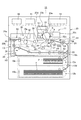
まず、本発明の第1の実施の形態について説明する。第1の実施の形態に係るプリンタ10(画像形成装置)は、電子写真方式のレーザビームプリンタである。プリンタ10は、図1に示すように、シートを給送する給送部12a,12bと、給送部12a,12bから給送されたシートを搬送する本体搬送部21(第2搬送ユニット)と、を備えている。また、プリンタ10は、装置本体20に対して引き出し可能に設けられ、シートを搬送する引き出し搬送部13(第1搬送ユニット)と、搬送されるシートに画像を形成する作像部11と、制御部14と、を有している。
<First Embodiment>
〔overall structure〕
First, a first embodiment of the present invention will be described. The printer 10 (image forming apparatus) according to the first embodiment is an electrophotographic laser beam printer. As shown in FIG. 1, the
給送部12a,12bは、互いに異なるサイズのシートPを収納するカセット16a,16bをそれぞれ有している。給送部12a,12bから給送されたシートPは、縦パスローラ対12c,12dの一方又は双方によって本体搬送部21に搬送される。本体搬送部21は、シート搬送パスH1上のシートを搬送する搬送ローラ対56と、両面搬送パスH2上のシートを搬送する搬送ローラ対55と、を有している。
The
作像部11は、感光ドラム15と、感光ドラム15の表面を一様に帯電させる帯電器23aと、帯電した感光ドラム15の表面に画像信号に応じたレーザを照射して静電潜像を形成させるスキャナ部23bと、を有している。また、作像部11は、この静電潜像を現像してトナー像を形成する現像部23cと、感光ドラム15の表面上に残ったトナーを回収するクリーニング部23dと、を有している。
The
引き出し搬送部13は、レジスト装置17と、転写ユニット30と、転写ベルト移動機構40と、定着装置18(定着部)と、排出搬送部28と、両面搬送部26と、を有している。レジスト装置17は、シートの斜行を補正すると共に所定のタイミングでシートを搬送するレジストレーションローラ対22a,22bを有している。転写ユニット30は、駆動ローラ33及び張架ローラ34に巻き掛けられる転写ベルト31を有しており、転写ベルト移動機構40は、カム駆動モータMによって回転駆動される転写ベルト昇降カム27を有している。
The
定着装置18は、加熱ローラ19a及び加圧ローラ19bを有しており、これら加熱ローラ19a及び加圧ローラ19bによって定着ニップN2が形成されている。排出搬送部28は、シートを排出ローラ対28a又は両面搬送部26の搬送ローラ対28bのいずれかに案内する案内部材25を有している。両面搬送部26は、シートを本体搬送部21に案内する両面搬送パスH2と、シートを反転させるための反転搬送パスH3と、シートを搬送する複数の搬送ローラ対と、を有している。
The
次に、プリンタ10による画像形成動作について説明する。給送部12a,12bから本体搬送部21を通ってレジスト装置17に搬送されたシートPは、レジストレーションローラ対22a,22bに先端が突き当てられて、斜行が補正される。そして、シートPは、所定のタイミングで感光ドラム15及び転写ローラ35によって形成される転写ニップN1(画像形成部)に搬送される。転写ニップNでは、転写ローラ35にトナー像とは逆極性の電圧が印加されることで、シートPに感光ドラム15上に形成されたトナー像が転写される。なお、転写ベルト31は、転写ベルト昇降カム27によって、画像形成タイミングやシート搬送タイミングに応じて、感光ドラム15に対して接離する。
Next, an image forming operation by the
トナー像が転写されたシートPは、転写ベルト31に静電吸着されつつ定着装置18に搬送され、加熱ローラ19a及び加圧ローラ19bによってトナー像が定着される。更にシートPは排出搬送部28の案内部材25によって排出ローラ対28aに搬送されて、機外に排出される。
The sheet P on which the toner image is transferred is conveyed to the
シートを反転させた状態で機外に排出する場合には、シートPは案内部材25によって両面搬送部26の反転搬送パスH3に案内され、反転ローラ対29によってスイッチバックされて排出ローラ対28aに搬送される。シートの両面に画像を形成する場合には、シートPは、反転搬送パスH3に搬送された後に両面搬送パスH2に搬送され、転写ニップN1によって裏面にも画像が形成される。
When the sheet P is discharged outside the apparatus in a reversed state, the sheet P is guided to the reverse conveyance path H3 of the double-sided
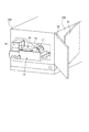
また、プリンタ10の前側面10A(第1の側面)には、図2に示すように、前扉60(第1扉部)が開閉可能に設けられており、前側面とは異なる右側面10B(第2の側面)には、右扉61(第2扉部)が開閉可能に設けられている。引き出し搬送部13は、前扉60が開状態となることで装置本体20から引き出すことができ、本体搬送部21は、右扉61が開状態となることで外方に露出し、紙詰まり処理等のメンテナンスを行うことができる。なお、前扉60は、不図示のオイルダンパによって開状態で保持することができる。
Further, as shown in FIG. 2, a front door 60 (first door portion) is provided on the
本体搬送部21と引き出し搬送部13とは、図1に示すように、シート搬送パスH1上の第1境界部54と両面搬送パスH2上の第2境界部53において、互いに離間することができる。第2境界部53から第1境界部54までの搬送路の長さと、転写ニップN1から定着ニップN2までの距離とは、A4サイズのシートの長さよりも長く設定されている。
As shown in FIG. 1, the main
シートPが第1境界部54又は第2境界部53において本体搬送部21と引き出し搬送部13との間に跨った状態で、引き出し搬送部13が装置本体20から引き出されると、シートPが破れたり激しく皺になったりしてしまう。このため、本実施の形態では、第2境界部53において紙詰まりが発生すると、強制的にレジスト装置17にシートPを送り込むように制御されている。これにより、小サイズのシートを第1境界部54に比して紙詰まり処理しにくい第2境界部53において、シートが停止してしまうことを防止することができる。
When the
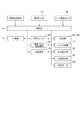
また、プリンタ10は、図1及び図3に示すように、監視センサ41及びシート搬送センサ42を有しており、監視センサ41は、定着装置18など装置各部の電圧や温度等を検出する。シート搬送センサ42は、シート搬送経路内のシート通過タイミングやシートの位置を検出する。
Further, as shown in FIGS. 1 and 3, the
制御部14は、画像形成信号に加え、監視センサ41及びシート搬送センサ42の検出信号に基づいて、装置各部の電圧や温度、シート搬送経路内各部の動作、及びシート搬送経路内の各搬送ローラを駆動する搬送モータ(図示せず)の制御を行う。また、制御部14は、監視センサ41及びシート搬送センサ42の検出結果から装置各部の異常や紙詰まりを判断して、状態に応じて復帰処理や画像形成動作の停止処理を行う。
Based on the detection signals of the
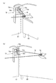
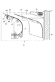
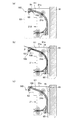
次に、本発明の要部である連動機構70について説明する。連動機構70は、図4に示すように、本体搬送部21に固定されたスライド軸63に沿って移動可能なスライド部材65(移動部)と、スライド部材65の位置に応じて右扉61を前扉60に連動して開かせる連動部71と、を有している。
Next, the interlocking
スライド軸63は、シート搬送方向に直交するシートの幅方向に延び、スライド部材65を幅方向に案内する。また、スライド軸63は、スライド部材65を回動可能に支持している。スライド部材65は、スライドバネ64によって、幅方向において前扉60から離れる方向に付勢されており、図4(a)に示すように、前扉60が閉じた状態では本体搬送部21のフレーム部材23に突き当たって待機位置で停止している。なお、スライド部材65は、スライド軸63を中心とする回動方向において、自重により図4に示す第2位置で保持されている。
The
スライド部材65は、第1境界部54において停止したシートに当接可能な当接部66と、止め輪67と、板バネ68と、を有している。当接部66は、前扉60から離れる方向に向かって上り傾斜する傾斜面66aを有している。スライド部材65は、待機位置においてはシート搬送領域外に位置しており、図4(c)に示すようにスライドバネ64(スライド付勢部)の付勢力に抗して前扉60に近づくと、第1境界部54において停止したシートに当接可能となる。
The
連動部71は、右扉61を閉じた状態でロックするロック部72と、前扉60を介してスライド部材65と後述するロック部72の係合爪72b(図5参照)とを連結する連結部73と、右扉61を開かせる方向に付勢する扉バネ74と、を有している。また、連動部71は、図4(b)に示すように、スライド部材65の板バネ68に当接可能な抵抗ブロック76(規制部)を有している。
The interlocking
ロック部72は、図5に示すように、右扉61に設けられるロック輪72aと、装置本体20に設けられロック輪72aに対して係合可能な係合爪72bと、係合爪72bがロック輪72aに係合するように付勢するロックバネ72dと、を有している。係合爪72bは、軸72cを中心に回動可能であり、止め輪72eが形成されている。
As shown in FIG. 5, the
係合爪72b(第2係合部)がロック輪72a(第1係合部)に係合する係合位置からロック輪72aに係合しない非係合位置に移動すると、右扉61のロックが解除され、右扉61は、図6に示すように、扉バネ74の付勢力によって開き動作する。右扉61には、シート搬送パスH1の一部である上部ガイド21a(案内ガイド部)が固定されており、上部ガイド21aは、下部ガイド21b(案内ガイド部)に対向している。このため、右扉61が開かれると、上部ガイド21aと下部ガイド21bとが離間し、上部ガイド21aと下部ガイド21bとの間の紙詰まりを処理することができる。
When the
連結部73は、一端がスライド部材65の止め輪67に固定され、他端が係合爪72bの止め輪72eに固定されるワイヤWと、前扉60に固定されワイヤWが巻き掛けられる滑車75と、を有している。
The connecting
次に、前扉60が開かれた際の各部の動作について説明する。まず、第1境界部54にシートが停止している時、すなわち本体搬送部21と引き出し搬送部13との間にシートが跨った状態で紙詰まりが起こった時について説明する。
Next, the operation of each part when the
前扉60がユーザによって開かれると、滑車75がワイヤWを装置手前側に引っ張る。本実施の形態では、スライド部材65とスライド軸63との間には例えば100μmの隙間が設けられており、スライド部材65とスライド軸63との間の摩擦は、ロックバネ72dの付勢力よりも十分に小さく設定されている。このため、滑車75によってワイヤWが引っ張られると、ワイヤWの他端が連結された係合爪72bは動かず、スライド部材65が図4(a)の矢印F方向に移動する。
When the
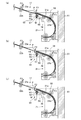
すると、スライド部材65の当接部66は、シートの幅方向における端部に当接する。このとき、当接部66には傾斜面66aが形成されているため、スライド部材65は、矢印F方向に移動しつつ、シートの下に潜り込むように回動する。このようにシートとスライド部材65とが当接すると、スライド部材65は、図7(a)に点線で示すようにシートを持ち上げようとする。このとき、シートは、搬送ローラ対56及びレジストレーションローラ対22a,22bによって所定の加圧力F3で挟持されている。このため、スライド部材65には、加圧力F3及びこれらのローラ対の不図示のベアリングにおける転がり摩擦によって決定される抗力F2が作用する。
Then, the
スライド部材65とスライド軸63との間には、上述したように僅かな隙間が設けられており、スライド部材65を回動させるために必要な力F1は、抗力F2よりも小さく設定されている(F1<F2)。一例として、レジストレーションローラ対22a,22b及び搬送ローラ対56の加圧力F3を1000gf、ベアリングの転がり摩擦の摩擦係数を0.05とすると、抗力F2は、
1000gf×0.05×2(カ所)=100gfとなる。
As described above, a slight gap is provided between the
1000 gf × 0.05 × 2 (location) = 100 gf.
そして、スライド部材65とスライド軸63との間の隙間を100μmに設定することでF1を10gfに設定する。これにより、スライド部材65は、シートPと当接することで確実に回動することができる。
And F1 is set to 10 gf by setting the clearance gap between the
また、スライド軸63は、引き出し搬送部13と本体搬送部21との間において、上部ガイド21a及び下部ガイド21bよりも下方に配置されている。当接部66の傾斜面66aは、当接部66がシートに当接していない状態(例えば図4(b)(c)に示す状態)で、下端が下部ガイド21bよりも下方に位置し、上端が上部ガイド21aよりも上方に位置している。このため、当接部66の傾斜面66aとシートPの端部とが確実に当接し、スライド部材65は確実に回動することができる。
The
スライド部材65がシートPに当接して図7(b)に示す第1位置まで回動し、かつスライド軸63に沿って幅方向にスライド移動すると、板バネ68が抵抗ブロック76に当接する。この状態でスライド部材65が更にワイヤWによって引っ張られて前扉60に近づくと、図7(c)に示すように板バネ68が撓む(弾性変形する)。この撓みが所定量に達すると、スライド部材65は抵抗ブロック76を乗り越えて更に前扉60に近づく方向に移動する。この時、板バネ68を屈曲させて板バネ68と抵抗ブロック76との間に発生する摩擦力を力F4と定義する。
When the
また、係合爪72bが係合位置から非係合位置に移動するために、ロックバネ72dの付勢力に抗して回動する際の力を力F5と定義する。そして、板バネ68の撓み量が大きくなるに従って力F4が力F5よりも大きくなると、ワイヤWはスライド部材65の止め輪67ではなく、係合爪72bの止め輪72eを引っ張り始める。
In addition, the force at which the engaging
力F5は、扉バネ74(扉付勢部材)によって係合爪72bとロック輪72aとの間に発生する摩擦力と、ロックバネ72dを縮める力の合力である。一例として、扉バネ74の弾性力を500gfに設定すると、金属材の係合爪72bとPOM材のロック輪72aとの間の摩擦係数は一般的に0.2程度であり、摩擦力は100gfとなる。更に、係合爪72bが係合位置から非係合位置に移動する際にロックバネ72dを縮めるために必要な力を50gfに設定すると、力F5は150gfとなる。従って、力F4が150gfよりも大きくなると、係合爪72bが非係合位置に移動し、ロック部72によるロックが解除される。
The force F5 is a resultant force of the frictional force generated between the engaging
すなわち、係合爪72bが係合位置から非係合位置に移動する際に係合爪72bからワイヤWに作用する負荷は、板バネ68が抵抗ブロック76に当接するまでにスライド部材65からワイヤWに作用する負荷よりも高く設定されている。このため、前扉60が開き動作された当初は、前扉60の開き動作に連動して、スライド部材65が前扉60及び抵抗ブロック76に近づく方向に移動する。
That is, when the
また、係合爪72bが係合位置から非係合位置に移動する際に係合爪72bからワイヤWに作用する負荷は、板バネ68が抵抗ブロック76に当接して弾性変形する際にスライド部材65からワイヤWに作用する負荷よりも低く設定されている。このため、板バネ68が所定量撓んだ後に前扉60に固定された滑車75によってワイヤWが引っ張られると、係合爪72bが係合位置から非係合位置に移動する。
The load acting on the wire W from the
係合爪72bが非係合位置においてワイヤWに対して移動不能となると、再度スライド部材65が前扉60に向けてスライド軸63に沿って移動する。そして、板バネ68が抵抗ブロック76を乗り越え、スライド部材65は、図4(c)に示す中央位置まで移動する。これにより、前扉60の開き動作が完了する。なお、本実施の形態では、板バネ68が抵抗ブロック76を乗り越える際の力F4を300gfに設定している。
When the
また、スライド部材65の板バネ68が抵抗ブロック76に当接するか否かは、スライド部材65がシートPに当接して第1位置に回動するか、シートPに当接しないで第2位置に位置するか、によって決まる。そして、連動部71は、スライド部材65が第1位置に位置している状態で右扉61を開かせ、スライド部材65が第2位置に位置している状態で右扉61を閉状態に保持する。
Whether or not the
右扉61が前扉60に連動して開かれ、ユーザによって第1境界部54に停止しているシートPが除去されると、スライド部材65は、自重によって第1位置から第2位置に回動する。更に、ユーザによる前扉60の閉動作及びスライドバネ64の付勢力により、スライド部材65は、抵抗ブロック76に当接することなく図4(a)に示す位置に復帰する。
When the
次いで、第1境界部54にシートが停止していない時、すなわち本体搬送部21と引き出し搬送部13との間にシートが跨っていない状態で前扉60を開動作した際の連動機構70の動きについて説明する。スライド部材65は、前扉60の開動作に連動して、スライド部材65が前扉60に近づく方向に移動する。しかし、スライド部材65はシートPに当接しないために回動せずに第2位置に位置したままスライド軸63に沿ってスライド移動する。このため、スライド部材65の板バネ68と抵抗ブロック76とが当接せず、力F4が力F5よりも大きくなることはない。
Next, when the sheet is not stopped at the
すると、ロック部72の係合爪72bがワイヤWによって回動することがないため、右扉61が閉状態でロックされたままスライド部材65が図4(c)に示す位置まで移動する。これにより、前扉60の開き動作が完了する。ユーザは、引き出し搬送部13を引き出して引き出し搬送部13内の紙詰まりを処理したのち、前扉60を閉じ、スライド部材65は、図4(a)に示す位置に復帰する。
Then, since the
また、シートPの紙詰まりが発生していない通常搬送時には、スライド部材65は、図4(a)に示すようにシート搬送領域外に位置しているため、シートPの搬送を妨げることはない。
Further, at the time of normal conveyance in which the paper P is not jammed, the
以上のように、本実施の形態によれば、第1境界部54にシートが停止している状態においては、前扉60の開動作に連動して、右扉61を開くことができ、ユーザに右扉61側から紙詰まり処理をするように促すことができる。これにより、誤った手順でシートを除去することを低減して、シートが破れたり、破れたシートが装置本体20内に残ったりすることを防止でき、メンテナンス性を向上することができる。
As described above, according to the present embodiment, when the seat is stopped at the
また、右扉61を前扉60に連動して開ける動作において、メカ的な構成を適用してセンサや動力源を設けていないためコストダウンすることができる。また、タブシートのための専用のセンサを設ける必要もなく、スリープ時であっても右扉61の連動動作を行うことができる。
Further, in the operation of opening the
なお、連結部73は、ワイヤ及び滑車に限らず、リンク機構等によって実現してもよい。また、板バネ68に代えて、ゴムや樹脂等の他の弾性部材を設けてもよい。また、本実施の形態において適用した力の数値は、一例にすぎず、これに限定されるものではない。
The connecting
また、本実施の形態では、板バネ68が抵抗ブロック76を乗り越え可能な構成としたが、乗り越え不能に構成してもよい。すなわち、シートPに当接して第1位置に位置するスライド部材65が当接し、かつシートPに当接せずに第2位置に位置するスライド部材65が当接しないストッパを設けてもよい。これにより、スライド部材65がストッパに当接すると、ロック部72のロックが解除される。
In the present embodiment, the
<第2の実施の形態>
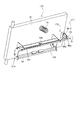
次いで、本発明の第2の実施の形態について説明するが、第1の実施の形態と同様の構成については、図示を省略、又は図に同一符号を付して説明する。右扉61を前扉60の開動作に連動して開放する連動機構170は、図8に示すように、フラグ部165(移動部)と、連動部171と、を有している。
<Second Embodiment>
Next, a second embodiment of the present invention will be described, but the same configuration as that of the first embodiment will be omitted or described with the same reference numerals. As shown in FIG. 8, the
フラグ部165は、スライド軸63にスライド移動可能かつ回動可能に支持されており、検出フラグ166(当接部)と、スライド軸63の径方向に突出する突出部80と、を有している。検出フラグ166は、幅方向において、シート搬送領域内に配置され、突出部80は、後述する解除レバー90の一端部90aに当接可能に構成されている。また、フラグ部165は、スライドバネ164によって前扉60に近づく方向に付勢されていると共に、不図示のねじりコイルバネにより矢印G方向に付勢されている。
The
連動部171は、右扉61を閉状態でロックするロック部172と、解除レバー90(解除部)と、扉バネ74と、ストッパ91(図9参照)と、を有している。ロック部172は、図9及び図10に示すように、右扉61のフレーム92に回動可能に支持されるロック輪93(第1係合部)と、装置本体20に固定されるロック爪94(第2係合部)と、を有している。ロック輪93は、コイルバネ95によってロック爪94に係合するように付勢されている。
The interlocking
解除レバー90は、回動軸90cを中心に回動可能に構成され、回動軸90cの一端側に延びる一端部90aと、他端側に延びる他端部90bと、を有している。また、解除レバー90は、コイルバネ90dによって図10に示す姿勢となるように付勢されており、他端部90bは、ロック輪93に当接可能に構成されている。解除レバー90は、一端部90aが突出部80に押圧されることで、他端部90bがロック輪93とロック爪94との係合を解除する解除位置と、他端部90bがロック輪93とロック爪94との係合を解除しない非解除位置と、の間を回動可能である。
The
ストッパ91(移動規制部)は、前扉60に固定されており、フラグ部165の突出部80に当接することで、フラグ部165のスライド移動及び回動を規制している。前扉60が閉状態の際には、フラグ部165は、図11(a)及び図12(a)に示す位置に位置している。この時、フラグ部165の検出フラグ166は、上部ガイド21a及び下部ガイド21bによって形成されるシート搬送パスH1に突出していない。また、突出部80は、幅方向において、僅かに解除レバー90の一端部90aから離間している。
The stopper 91 (movement restricting portion) is fixed to the
次に、前扉60が開かれた際の各部の動作について説明する。まず、第1境界部54にシートが停止している時、すなわち本体搬送部21Aと引き出し搬送部13との間にシートが跨った状態で紙詰まりが起こった時について説明する。
Next, the operation of each part when the
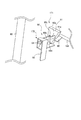
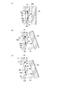
前扉60がユーザによって開かれると、前扉60に固定されたストッパ91の傾斜面91aがフラグ部165から退避する。すると、フラグ部165は、不図示のねじりコイルバネの付勢力によってスライド軸63を中心に回動する。これにより、フラグ部165は、シート搬送パスH1に進入して、図11(b)に示すように、検出フラグ166がシートPのシート面に当接する第1位置に位置する。フラグ部165が第1位置に位置する状態では、突出部80は、解除レバー90の一端部90aに対して幅方向から視て重なっている。
When the
これと同時に、フラグ部165は、図12(b)に示すように、スライドバネ164の付勢力によってスライド軸63に沿って幅方向に移動し、突出部80がコイルバネ90d,95の付勢力に抗して解除レバー90の一端部90aを押圧する。これにより、解除レバー90が非解除位置から解除位置へと移動し、ロック爪94とロック輪93との係合が解除される。すると、右扉61は、図12(c)に示すように、扉バネ74の付勢力によって開状態となる。
At the same time, as shown in FIG. 12B, the
シートPが除去されると、ユーザは、右扉61を閉じた後、前扉60を閉じる。前扉60が閉じられると、ストッパ91の傾斜面91aによって突出部80が押圧され、フラグ部165が図9に示す状態に復帰する。
When the sheet P is removed, the user closes the
一方、第1境界部54にシートPが停止していない場合に前扉60がユーザによって開かれると、フラグ部165は、図11(c)に示すように、検出フラグ166がシート搬送パスH1に突出する第2位置に位置する。この時、突出部80は、解除レバー90の一端部90aに対して幅方向から視て重なっていない。このため、前扉60が開かれても突出部80によって解除レバー90の一端部90aが押圧されず、ロック爪94とロック輪93との係合は解除されない。
On the other hand, when the
以上のように、第2の実施の形態では、シートPを検出する検出フラグ166をシート搬送パスH1の略中央に配置することで、シートPのシート面と検出フラグ166とを接触させることができる。これにより、第1の実施の形態のようにシートPの端部とスライド部材65とを接触させる場合に比して、シートPへのダメージを低減させることができる。よって、シートPの再利用が可能となり、ユーザの利便性を向上することができる。また、シートの剛度に依存しなくなるため、薄紙でも確実に右扉61を開放することができる。
As described above, in the second embodiment, the
10:画像形成装置(プリンタ)/10A:第1の側面(前側面)/10B:第2の側面(右側面)/13:第1搬送ユニット(引き出し搬送部)/18:定着部(定着装置)/20:装置本体/21:第2搬送ユニット(本体搬送部)/21a,21b:案内ガイド部(上部ガイド、下部ガイド)/60:第1扉部(前扉)/61:第2扉部(右扉)/63:スライド軸/64,164:スライド付勢部(スライドバネ)/65:移動部(スライド部材)/66:当接部/66a:傾斜面/68:弾性部(板バネ)/70,170:連動機構/71,171:連動部/72,172:ロック部/72a:第1係合部(ロック輪)/72b:第2係合部(係合爪)/73:連結部/74:扉付勢部材(扉バネ)/75:滑車/76:規制部(抵抗ブロック)/90:解除部(解除レバー)/91:移動規制部(ストッパ)/93:第1係合部(ロック輪)/94:第2係合部(ロック爪)/165:移動部(フラグ部)/166:当接部(検出フラグ)/N1:画像形成部(転写ニップ)/P:シート/W:ワイヤ 10: image forming apparatus (printer) / 10A: first side surface (front side surface) / 10B: second side surface (right side surface) / 13: first transport unit (drawer transport unit) / 18: fixing unit (fixing device) ) / 20: apparatus main body / 21: second transport unit (main body transport section) / 21a, 21b: guide guide section (upper guide, lower guide) / 60: first door section (front door) / 61: second door Part (right door) / 63: slide shaft / 64, 164: slide urging part (slide spring) / 65: moving part (slide member) / 66: contact part / 66a: inclined surface / 68: elastic part (plate) Spring) / 70, 170: interlocking mechanism / 71, 171: interlocking part / 72, 172: locking part / 72a: first engaging part (locking wheel) / 72b: second engaging part (engaging claw) / 73 : Connection part / 74: Door urging member (door spring) / 75: Pulley / 76: Restriction part ( Anti-block) / 90: Release part (release lever) / 91: Movement restriction part (stopper) / 93: First engagement part (lock ring) / 94: Second engagement part (lock claw) / 165: Movement part (Flag part) / 166: contact part (detection flag) / N1: image forming part (transfer nip) / P: sheet / W: wire
Claims (18)
前記第1扉部が開状態となることで前記装置本体に対して引き出し可能に設けられ、シートを搬送する第1搬送ユニットと、
前記第2扉部が開状態となることで露出され、シートを搬送する第2搬送ユニットと、
前記第1搬送ユニット及び前記第2搬送ユニットにシートが跨った状態における前記第1扉部の開き動作に連動して、前記第2扉部を開かせる連動機構と、を備える、
ことを特徴とするシート搬送装置。 An apparatus main body having a first door portion provided on the first side surface and capable of opening and closing; and a second door portion provided on a second side surface different from the first side surface and capable of opening and closing;
A first transport unit configured to be able to be pulled out with respect to the apparatus main body when the first door portion is in an open state, and transports a sheet;
A second conveyance unit that is exposed when the second door portion is in an open state and conveys a sheet; and
An interlocking mechanism for opening the second door portion in conjunction with the opening operation of the first door portion in a state where a sheet straddles the first transport unit and the second transport unit,
A sheet conveying apparatus.
前記第1扉部の開き動作に連動して、前記第1搬送ユニット及び前記第2搬送ユニットにシートが跨った状態では第1位置に位置し、かつ前記第1搬送ユニット及び前記第2搬送ユニットにシートが跨っていない状態では第2位置に位置する移動部と、
前記移動部が前記第1位置に位置する状態で前記第2扉部を開かせ、前記移動部が前記第2位置に位置する状態で前記第2扉部を閉状態に保持する連動部と、を有する、
ことを特徴とする請求項1に記載のシート搬送装置。 The interlocking mechanism is
In conjunction with the opening operation of the first door portion, the first conveyance unit and the second conveyance unit are located at the first position in a state where a sheet is straddling the first conveyance unit and the second conveyance unit. In a state where the sheet does not straddle, the moving unit located at the second position;
An interlocking portion that opens the second door portion in a state where the moving portion is located in the first position, and holds the second door portion in a closed state in a state where the moving portion is located in the second position; Having
The sheet conveying apparatus according to claim 1.
前記第2扉部を開かせる方向に付勢する扉付勢部材と、
前記第2扉部に設けられる第1係合部と、前記装置本体に設けられ前記第1係合部に係合可能な第2係合部と、を有し、前記第1係合部及び前記第2係合部が係合することで前記第2扉部を閉じた状態でロックするロック部と、を有する、
ことを特徴とする請求項2に記載のシート搬送装置。 The interlocking unit is
A door urging member that urges the second door portion in a direction to open the second door portion;
A first engagement portion provided in the second door portion; and a second engagement portion provided in the apparatus main body and engageable with the first engagement portion, wherein the first engagement portion and A lock portion that locks the second door portion in a closed state by engaging the second engagement portion;
The sheet conveying apparatus according to claim 2.
前記連動部は、前記第1扉部を介して、前記移動部と前記第2係合部とを連結する連結部を有する、
ことを特徴とする請求項3に記載のシート搬送装置。 The second engagement portion is configured to be movable between an engagement position that engages with the first engagement portion and a non-engagement position that does not engage with the first engagement portion,
The interlocking part has a connecting part that connects the moving part and the second engaging part via the first door part.
The sheet conveying apparatus according to claim 3.
ことを特徴とする請求項4に記載のシート搬送装置。 In the state where the moving part is located at the first position, the connecting part moves the second engaging part from the engaging position to the non-engaging position in conjunction with the opening operation of the first door part. Move,
The sheet conveying apparatus according to claim 4.
前記移動部を前記幅方向において前記第1扉部とは離れる方向に付勢するスライド付勢部と、を備え、
前記連動部は、前記第1位置に位置する前記移動部に当接し、前記幅方向において前記移動部が前記第1扉部に近づくことを規制する規制部を有する、
ことを特徴とする請求項4又は5に記載のシート搬送装置。 A slide shaft extending in the width direction orthogonal to the sheet conveying direction and guiding the moving unit in the width direction;
A slide urging portion that urges the moving portion in a direction away from the first door portion in the width direction,
The interlocking portion has a restricting portion that contacts the moving portion located at the first position and restricts the moving portion from approaching the first door portion in the width direction.
The sheet conveying apparatus according to claim 4, wherein the sheet conveying apparatus is a sheet conveying apparatus.
ことを特徴とする請求項6に記載のシート搬送装置。 The moving part has a contact part capable of contacting a sheet straddling the first transport unit and the second transport unit, and the moving part moves along the slide shaft along with the opening operation of the first door part. While moving in the width direction against the urging force of the slide urging portion, the abutting portion abuts against a sheet straddling the first conveyance unit and the second conveyance unit and rotates around the slide shaft. Moved to the first position,
The sheet conveying apparatus according to claim 6.
前記スライド軸は、前記第1搬送ユニットと前記第2搬送ユニットとの間において、前記案内ガイド部の下方に配置され、
前記当接部は、前記第1扉部から離れる方向に向かって上り傾斜する傾斜面を有する、
ことを特徴とする請求項7に記載のシート搬送装置。 A guide guide unit for guiding a sheet conveyed to the second conveyance unit;
The slide shaft is disposed below the guide guide portion between the first transport unit and the second transport unit,
The contact portion has an inclined surface that is inclined upward in a direction away from the first door portion,
The sheet conveying apparatus according to claim 7.
ことを特徴とする請求項6乃至8のいずれか1項に記載のシート搬送装置。 The moving part has an elastic part that abuts on the restricting part and elastically deforms,
The sheet conveying apparatus according to claim 6, wherein the sheet conveying apparatus is a sheet conveying apparatus.
ことを特徴とする請求項9に記載のシート搬送装置。 When the second engagement portion moves from the engagement position to the non-engagement position, the load that acts on the connection portion from the second engagement portion is elastic because the elastic portion abuts on the restriction portion. It is set lower than the load acting on the connecting part from the moving part when deforming,
The sheet conveying apparatus according to claim 9.
ことを特徴とする請求項9又は10に記載のシート搬送装置。 When the second engagement portion moves from the engagement position to the non-engagement position, the load that acts on the connection portion from the second engagement portion is until the elastic portion abuts on the restriction portion. It is set higher than the load acting on the connecting part from the moving part,
The sheet conveying apparatus according to claim 9 or 10, characterized in that
前記第1扉部に設けられ、前記ワイヤが巻き掛けられる滑車と、を有する、
ことを特徴とする請求項4乃至11のいずれか1項に記載のシート搬送装置。 The connecting portion has one end fixed to the moving portion and the other end fixed to the second engaging portion;
A pulley provided on the first door portion, on which the wire is wound,
The sheet conveying apparatus according to claim 4, wherein the sheet conveying apparatus is a sheet conveying apparatus.
前記第1係合部及び前記第2係合部の係合を解除する解除位置と、前記第1係合部及び前記第2係合部の係合を解除しない非解除位置と、の間を移動可能に構成される解除部と、
前記第1扉部に設けられ、前記第1扉部が閉状態の際に前記移動部の移動を規制する移動規制部と、を有し、
前記移動部は、前記第1扉部の開動作に連動して、前記移動部が前記第1位置に位置する状態で前記解除部を前記解除位置に位置させる、
ことを特徴とする請求項3に記載のシート搬送装置。 The interlocking unit is
Between a release position where the engagement of the first engagement portion and the second engagement portion is released and a non-release position where the engagement of the first engagement portion and the second engagement portion is not released. A release unit configured to be movable;
A movement restricting portion that is provided on the first door portion and restricts movement of the moving portion when the first door portion is in a closed state;
The moving part is interlocked with the opening operation of the first door part, and the releasing part is located at the releasing position in a state where the moving part is located at the first position.
The sheet conveying apparatus according to claim 3.
ことを特徴とする請求項13に記載のシート搬送装置。 The moving unit includes a contact portion that is provided in a sheet conveyance region and can contact a sheet straddling the first conveyance unit and the second conveyance unit, and is arranged in a width direction orthogonal to the sheet conveyance direction. Configured to be movable and rotatable,
The sheet conveying apparatus according to claim 13.
前記移動部は、前記第1扉部の開動作に連動して、前記当接部が前記第1搬送ユニット及び前記第2搬送ユニットに跨ったシートに当接して前記第1位置に位置した状態で前記スライド付勢部によって前記幅方向に移動する、
ことを特徴とする請求項14に記載のシート搬送装置。 The interlocking portion has a slide urging portion that urges the moving portion to approach the first door portion in the width direction,
The moving unit is located in the first position in contact with the sheet straddling the first transport unit and the second transport unit in conjunction with the opening operation of the first door unit. And moves in the width direction by the slide urging portion,
The sheet conveying apparatus according to claim 14.
前記当接部は、前記第1扉部が閉状態の際には前記案内ガイド部から退避し、前記第1扉部が開状態の際には前記案内ガイド部に進入する、
ことを特徴とする請求項14又は15に記載のシート搬送装置。 A guide guide unit for guiding a sheet conveyed to the second conveyance unit;
The contact portion retreats from the guide guide portion when the first door portion is closed, and enters the guide guide portion when the first door portion is open.
The sheet conveying apparatus according to claim 14, wherein the sheet conveying apparatus is a sheet conveying apparatus.
前記シート搬送装置によって搬送されるシートに画像を形成する画像形成部と、備える、
ことを特徴とする画像形成装置。 A sheet conveying apparatus according to any one of claims 1 to 16,
An image forming unit that forms an image on a sheet conveyed by the sheet conveying apparatus;
An image forming apparatus.
ことを特徴とする請求項17に記載の画像形成装置。 The first transport unit includes a fixing unit that fixes an image formed on a sheet by the image forming unit.
The image forming apparatus according to claim 17.
Priority Applications (1)
| Application Number | Priority Date | Filing Date | Title |
|---|---|---|---|
| JP2016081975A JP2017191279A (en) | 2016-04-15 | 2016-04-15 | Sheet conveying device and image forming apparatus |
Applications Claiming Priority (1)
| Application Number | Priority Date | Filing Date | Title |
|---|---|---|---|
| JP2016081975A JP2017191279A (en) | 2016-04-15 | 2016-04-15 | Sheet conveying device and image forming apparatus |
Publications (1)
| Publication Number | Publication Date |
|---|---|
| JP2017191279A true JP2017191279A (en) | 2017-10-19 |
Family
ID=60085953
Family Applications (1)
| Application Number | Title | Priority Date | Filing Date |
|---|---|---|---|
| JP2016081975A Pending JP2017191279A (en) | 2016-04-15 | 2016-04-15 | Sheet conveying device and image forming apparatus |
Country Status (1)
| Country | Link |
|---|---|
| JP (1) | JP2017191279A (en) |
Cited By (1)
| Publication number | Priority date | Publication date | Assignee | Title |
|---|---|---|---|---|
| JP2021169169A (en) * | 2020-04-15 | 2021-10-28 | セイコーエプソン株式会社 | Recording device |
-
2016
- 2016-04-15 JP JP2016081975A patent/JP2017191279A/en active Pending
Cited By (2)
| Publication number | Priority date | Publication date | Assignee | Title |
|---|---|---|---|---|
| JP2021169169A (en) * | 2020-04-15 | 2021-10-28 | セイコーエプソン株式会社 | Recording device |
| JP7592978B2 (en) | 2020-04-15 | 2024-12-03 | セイコーエプソン株式会社 | Recording device |
Similar Documents
| Publication | Publication Date | Title |
|---|---|---|
| US8047539B2 (en) | Image forming apparatus | |
| CN108116913B (en) | Sheet conveying apparatus and image forming apparatus having the same | |
| JP6541415B2 (en) | Sheet feeding apparatus and image forming apparatus | |
| JP2018070347A (en) | Sheet carrier device and image forming apparatus | |
| US10345754B2 (en) | Sheet conveying device and image forming apparatus incorporating the sheet conveying device | |
| JP2013184754A (en) | Sheet conveyer, and image forming device | |
| US10315868B2 (en) | Sheet feeding apparatus and image forming apparatus | |
| US20150021850A1 (en) | Sheet feeding device and image forming apparatus | |
| US9377749B2 (en) | Image forming apparatus | |
| JP3483418B2 (en) | Jam processing mechanism and image forming apparatus | |
| CN106950808B (en) | image forming apparatus | |
| US20120243019A1 (en) | Sheet feeding apparatus and image forming apparatus | |
| JP2006047647A (en) | Image forming apparatus | |
| US9696678B2 (en) | Sheet feeding apparatus and image forming apparatus | |
| JP2015086039A (en) | Sheet feeding apparatus and image forming apparatus | |
| JP4196200B2 (en) | Paper transport device | |
| JP3874058B2 (en) | Sheet transport device | |
| JP5287202B2 (en) | Image forming apparatus | |
| JP5773589B2 (en) | Sheet conveying apparatus and image forming apparatus | |
| JP2008169024A (en) | Sheet feeder, image forming device equipped with the same, and facsimile equipment | |
| JP2008151922A (en) | Fixing apparatus and image forming apparatus | |
| JP2016142908A (en) | Image forming apparatus | |
| JP2024020872A (en) | Sheet conveyance device and image forming device | |
| JP3554108B2 (en) | Sheet feeding apparatus and image forming apparatus having the same | |
| JP2872436B2 (en) | Image forming apparatus having re-feeding device |