JP2017191671A - Microwave heating device and exhaust purification device - Google Patents
Microwave heating device and exhaust purification device Download PDFInfo
- Publication number
- JP2017191671A JP2017191671A JP2016079489A JP2016079489A JP2017191671A JP 2017191671 A JP2017191671 A JP 2017191671A JP 2016079489 A JP2016079489 A JP 2016079489A JP 2016079489 A JP2016079489 A JP 2016079489A JP 2017191671 A JP2017191671 A JP 2017191671A
- Authority
- JP
- Japan
- Prior art keywords
- electromagnetic wave
- microwave
- unit
- power
- generation unit
- Prior art date
- Legal status (The legal status is an assumption and is not a legal conclusion. Google has not performed a legal analysis and makes no representation as to the accuracy of the status listed.)
- Granted
Links
Images
Classifications
-
- F—MECHANICAL ENGINEERING; LIGHTING; HEATING; WEAPONS; BLASTING
- F01—MACHINES OR ENGINES IN GENERAL; ENGINE PLANTS IN GENERAL; STEAM ENGINES
- F01N—GAS-FLOW SILENCERS OR EXHAUST APPARATUS FOR MACHINES OR ENGINES IN GENERAL; GAS-FLOW SILENCERS OR EXHAUST APPARATUS FOR INTERNAL-COMBUSTION ENGINES
- F01N3/00—Exhaust or silencing apparatus having means for purifying, rendering innocuous, or otherwise treating exhaust
- F01N3/02—Exhaust or silencing apparatus having means for purifying, rendering innocuous, or otherwise treating exhaust for cooling, or for removing solid constituents of, exhaust
- F01N3/021—Exhaust or silencing apparatus having means for purifying, rendering innocuous, or otherwise treating exhaust for cooling, or for removing solid constituents of, exhaust by means of filters
- F01N3/023—Exhaust or silencing apparatus having means for purifying, rendering innocuous, or otherwise treating exhaust for cooling, or for removing solid constituents of, exhaust by means of filters using means for regenerating the filters, e.g. by burning trapped particles
- F01N3/027—Exhaust or silencing apparatus having means for purifying, rendering innocuous, or otherwise treating exhaust for cooling, or for removing solid constituents of, exhaust by means of filters using means for regenerating the filters, e.g. by burning trapped particles using electric or magnetic heating means
- F01N3/028—Exhaust or silencing apparatus having means for purifying, rendering innocuous, or otherwise treating exhaust for cooling, or for removing solid constituents of, exhaust by means of filters using means for regenerating the filters, e.g. by burning trapped particles using electric or magnetic heating means using microwaves
-
- F—MECHANICAL ENGINEERING; LIGHTING; HEATING; WEAPONS; BLASTING
- F01—MACHINES OR ENGINES IN GENERAL; ENGINE PLANTS IN GENERAL; STEAM ENGINES
- F01N—GAS-FLOW SILENCERS OR EXHAUST APPARATUS FOR MACHINES OR ENGINES IN GENERAL; GAS-FLOW SILENCERS OR EXHAUST APPARATUS FOR INTERNAL-COMBUSTION ENGINES
- F01N3/00—Exhaust or silencing apparatus having means for purifying, rendering innocuous, or otherwise treating exhaust
- F01N3/08—Exhaust or silencing apparatus having means for purifying, rendering innocuous, or otherwise treating exhaust for rendering innocuous
- F01N3/10—Exhaust or silencing apparatus having means for purifying, rendering innocuous, or otherwise treating exhaust for rendering innocuous by thermal or catalytic conversion of noxious components of exhaust
- F01N3/18—Exhaust or silencing apparatus having means for purifying, rendering innocuous, or otherwise treating exhaust for rendering innocuous by thermal or catalytic conversion of noxious components of exhaust characterised by methods of operation; Control
- F01N3/20—Exhaust or silencing apparatus having means for purifying, rendering innocuous, or otherwise treating exhaust for rendering innocuous by thermal or catalytic conversion of noxious components of exhaust characterised by methods of operation; Control specially adapted for catalytic conversion
- F01N3/2006—Periodically heating or cooling catalytic reactors, e.g. at cold starting or overheating
- F01N3/2013—Periodically heating or cooling catalytic reactors, e.g. at cold starting or overheating using electric or magnetic heating means
- F01N3/202—Periodically heating or cooling catalytic reactors, e.g. at cold starting or overheating using electric or magnetic heating means using microwaves
-
- H—ELECTRICITY
- H05—ELECTRIC TECHNIQUES NOT OTHERWISE PROVIDED FOR
- H05B—ELECTRIC HEATING; ELECTRIC LIGHT SOURCES NOT OTHERWISE PROVIDED FOR; CIRCUIT ARRANGEMENTS FOR ELECTRIC LIGHT SOURCES, IN GENERAL
- H05B6/00—Heating by electric, magnetic or electromagnetic fields
- H05B6/64—Heating using microwaves
- H05B6/6447—Method of operation or details of the microwave heating apparatus related to the use of detectors or sensors
- H05B6/645—Method of operation or details of the microwave heating apparatus related to the use of detectors or sensors using temperature sensors
-
- H—ELECTRICITY
- H05—ELECTRIC TECHNIQUES NOT OTHERWISE PROVIDED FOR
- H05B—ELECTRIC HEATING; ELECTRIC LIGHT SOURCES NOT OTHERWISE PROVIDED FOR; CIRCUIT ARRANGEMENTS FOR ELECTRIC LIGHT SOURCES, IN GENERAL
- H05B6/00—Heating by electric, magnetic or electromagnetic fields
- H05B6/64—Heating using microwaves
- H05B6/647—Aspects related to microwave heating combined with other heating techniques
-
- H—ELECTRICITY
- H05—ELECTRIC TECHNIQUES NOT OTHERWISE PROVIDED FOR
- H05B—ELECTRIC HEATING; ELECTRIC LIGHT SOURCES NOT OTHERWISE PROVIDED FOR; CIRCUIT ARRANGEMENTS FOR ELECTRIC LIGHT SOURCES, IN GENERAL
- H05B6/00—Heating by electric, magnetic or electromagnetic fields
- H05B6/64—Heating using microwaves
- H05B6/70—Feed lines
- H05B6/705—Feed lines using microwave tuning
-
- H—ELECTRICITY
- H05—ELECTRIC TECHNIQUES NOT OTHERWISE PROVIDED FOR
- H05B—ELECTRIC HEATING; ELECTRIC LIGHT SOURCES NOT OTHERWISE PROVIDED FOR; CIRCUIT ARRANGEMENTS FOR ELECTRIC LIGHT SOURCES, IN GENERAL
- H05B6/00—Heating by electric, magnetic or electromagnetic fields
- H05B6/64—Heating using microwaves
- H05B6/80—Apparatus for specific applications
-
- F—MECHANICAL ENGINEERING; LIGHTING; HEATING; WEAPONS; BLASTING
- F01—MACHINES OR ENGINES IN GENERAL; ENGINE PLANTS IN GENERAL; STEAM ENGINES
- F01N—GAS-FLOW SILENCERS OR EXHAUST APPARATUS FOR MACHINES OR ENGINES IN GENERAL; GAS-FLOW SILENCERS OR EXHAUST APPARATUS FOR INTERNAL-COMBUSTION ENGINES
- F01N2240/00—Combination or association of two or more different exhaust treating devices, or of at least one such device with an auxiliary device, not covered by indexing codes F01N2230/00 or F01N2250/00, one of the devices being
- F01N2240/16—Combination or association of two or more different exhaust treating devices, or of at least one such device with an auxiliary device, not covered by indexing codes F01N2230/00 or F01N2250/00, one of the devices being an electric heater, i.e. a resistance heater
-
- Y—GENERAL TAGGING OF NEW TECHNOLOGICAL DEVELOPMENTS; GENERAL TAGGING OF CROSS-SECTIONAL TECHNOLOGIES SPANNING OVER SEVERAL SECTIONS OF THE IPC; TECHNICAL SUBJECTS COVERED BY FORMER USPC CROSS-REFERENCE ART COLLECTIONS [XRACs] AND DIGESTS
- Y02—TECHNOLOGIES OR APPLICATIONS FOR MITIGATION OR ADAPTATION AGAINST CLIMATE CHANGE
- Y02T—CLIMATE CHANGE MITIGATION TECHNOLOGIES RELATED TO TRANSPORTATION
- Y02T10/00—Road transport of goods or passengers
- Y02T10/10—Internal combustion engine [ICE] based vehicles
- Y02T10/12—Improving ICE efficiencies
Landscapes
- Engineering & Computer Science (AREA)
- Chemical & Material Sciences (AREA)
- Physics & Mathematics (AREA)
- Electromagnetism (AREA)
- Combustion & Propulsion (AREA)
- Mechanical Engineering (AREA)
- General Engineering & Computer Science (AREA)
- Chemical Kinetics & Catalysis (AREA)
- Health & Medical Sciences (AREA)
- Toxicology (AREA)
- Processes For Solid Components From Exhaust (AREA)
- Control Of High-Frequency Heating Circuits (AREA)
Abstract
【課題】正確にDPF等の再生時期を検知することのできるマイクロ波加熱装置を提供する。【解決手段】被加熱物が入れられる筐体部と、マイクロ波を発生させるマイクロ波発生部と、前記マイクロ波とは異なる周波数の電磁波を発生させる電磁波発生部と、前記電磁波発生部より前記筐体部に入射し、前記被加熱物を透過した電磁波のパワーを測定する電磁波センサと、前記電磁波センサにおいて検出された電磁波のパワーに基づき、前記マイクロ波発生部におけるマイクロ波の発生を制御する制御部と、を有することを特徴とするマイクロ波加熱装置により上記課題を解決する。【選択図】 図1A microwave heating apparatus capable of accurately detecting the regeneration timing of DPF or the like is provided. A casing unit in which an object to be heated is placed, a microwave generation unit that generates a microwave, an electromagnetic wave generation unit that generates an electromagnetic wave having a frequency different from the microwave, and the casing from the electromagnetic wave generation unit An electromagnetic wave sensor that measures the power of an electromagnetic wave incident on a body part and transmitted through the object to be heated, and a control that controls generation of microwaves in the microwave generation part based on the power of the electromagnetic wave detected by the electromagnetic wave sensor The above-mentioned problem is solved by a microwave heating device characterized by having a portion. [Selection] Figure 1
Description
本発明は、マイクロ波加熱装置及び排気浄化装置に関するものである。 The present invention relates to a microwave heating device and an exhaust purification device.
現在、排気に含まれるPM(Particulate matter)等の微粒子を捕集する装置として、DPF(Diesel Particulate Filter)が用いられた排気浄化装置が実用化されている。このような排気浄化装置は、使用によりDPFにPM等の微粒子が堆積するため、DPFを再生することが求められる。DPFを再生する方法としては、例えば、マイクロ波加熱装置から放射されたマイクロ波等の高周波電磁波を用いる方法が開示されている(例えば、特許文献1)。具体的には、この方法は、DPFにマイクロ波等の電磁波を照射することにより、DPFに堆積しているPM等の微粒子を加熱し、燃焼させることにより、DPFの再生を行う方法である。 Currently, an exhaust gas purification apparatus using a DPF (Diesel Particulate Filter) is put into practical use as a device for collecting particulates such as PM (Particulate matter) contained in exhaust gas. Such an exhaust purification device is required to regenerate the DPF because particulates such as PM accumulate on the DPF when used. As a method for regenerating the DPF, for example, a method using a high-frequency electromagnetic wave such as a microwave radiated from a microwave heating device is disclosed (for example, Patent Document 1). Specifically, this method is a method of regenerating the DPF by irradiating the DPF with electromagnetic waves such as microwaves to heat and burn particulates such as PM deposited on the DPF.
上述した排気浄化装置では、DPFの再生は、DPF内にPM等の微粒子がある程度堆積した後、DPFにマイクロ波等の電磁波を照射することにより、PM等の微粒子が加熱され、酸化分解されることにより行われる。しかしながら、DPFは、筐体に覆われているため、DPF内にPM等の微粒子が堆積しているかどうかは、外からは解らない。 In the exhaust purification apparatus described above, the regeneration of the DPF is performed by irradiating the DPF with electromagnetic waves such as microwaves after particulates such as PM are deposited to some extent in the DPF, thereby heating and oxidizing and oxidizing the particulates such as PM. Is done. However, since the DPF is covered with the housing, it is not known from the outside whether particulates such as PM are deposited in the DPF.
このため、例えば、マイクロ波センサにより検出されるマイクロ波の強度と内燃機関の動作時間との関係から再生時期を推定する再生時期判定マップを用いて、DPFの再生時期を判断し再生を行う方法が開示されている(例えば、特許文献3)。しかしながら、この方法では、マイクロ波の強度と内燃機関の動作時間より、DPFの再生時期を推定するものであるため、再生時期が正しく検知されない場合がある。DPFの再生時期が正しく検知されないと、無駄にマイクロ波を照射することや、DPF内にPM等の微粒子が堆積しているのに、DPFが再生されない等の問題が生じる。また、この方法では、再生時期判定マップ等を作製する必要や、この再生時期判定マップ等を記憶させておく必要があり、更には、再生時期を判断するための制御回路も複雑となり、判断に時間を要し、コストアップにもつながる。 Therefore, for example, a method for performing regeneration by determining the regeneration timing of the DPF using a regeneration timing determination map that estimates the regeneration timing from the relationship between the intensity of the microwave detected by the microwave sensor and the operation time of the internal combustion engine. Is disclosed (for example, Patent Document 3). However, in this method, the regeneration timing of the DPF is estimated from the intensity of the microwave and the operation time of the internal combustion engine, and thus the regeneration timing may not be detected correctly. If the regeneration timing of the DPF is not correctly detected, problems such as unnecessary irradiation of microwaves and accumulation of particulates such as PM in the DPF cause the DPF not to be regenerated. This method also requires the preparation of a regeneration time determination map, etc., and the storage of the regeneration time determination map, and the control circuit for determining the regeneration time is complicated. It takes time and increases costs.
本発明は、容易にDPF等の再生時期を検知することのできるマイクロ波加熱装置を提供することを目的とする。 An object of the present invention is to provide a microwave heating apparatus that can easily detect the regeneration timing of DPF or the like.
1つの態様では、マイクロ波加熱装置は、被加熱物が入れられる筐体部と、マイクロ波を発生させるマイクロ波発生部と、前記マイクロ波とは異なる周波数の電磁波を発生させる電磁波発生部と、前記電磁波発生部より前記筐体部に入射し、前記被加熱物を透過した電磁波のパワーを測定する電磁波センサと、前記電磁波センサにおいて検出された電磁波のパワーに基づき、前記マイクロ波発生部におけるマイクロ波の発生を制御する制御部と、を有する。 In one aspect, the microwave heating apparatus includes a casing unit in which an object to be heated is placed, a microwave generation unit that generates a microwave, an electromagnetic wave generation unit that generates an electromagnetic wave having a frequency different from the microwave, An electromagnetic wave sensor that measures the power of an electromagnetic wave that has entered the casing from the electromagnetic wave generator and has passed through the object to be heated, and a micro wave in the microwave generator based on the power of the electromagnetic wave detected by the electromagnetic wave sensor. A control unit that controls generation of waves.
1つの側面として、容易にDPF等の再生時期を検知することができる。 As one aspect, it is possible to easily detect the regeneration timing of DPF or the like.
実施するための形態について、以下に説明する。尚、同じ部材等については、同一の符号を付して説明を省略する。 The form for implementing is demonstrated below. In addition, about the same member etc., the same code | symbol is attached | subjected and description is abbreviate | omitted.
〔第1の実施の形態〕
(マイクロ波加熱装置及び排気浄化装置)
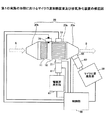
第1の実施の形態におけるマイクロ波加熱装置及び排気浄化装置について図1に基づき説明する。尚、本実施の形態における排気浄化装置には、本実施の形態におけるマイクロ波加熱装置が搭載されている。
[First Embodiment]
(Microwave heating device and exhaust purification device)
A microwave heating device and an exhaust emission control device in the first embodiment will be described with reference to FIG. In addition, the microwave heating apparatus in this Embodiment is mounted in the exhaust gas purification apparatus in this Embodiment.
本実施の形態における排気浄化装置は、微粒子捕集部10、酸化触媒部11、筐体部20、マイクロ波発生部30、電磁波発生部41、マイクロ波センサ50、第1の電磁波センサ51、第2の電磁波センサ52、温度測定部70、制御部80等を有している。
The exhaust purification device in the present embodiment includes a
微粒子捕集部10は、本実施の形態におけるマイクロ波加熱装置の被加熱物となるものであり、DPF等により形成されている。DPFは、例えば、隣り合う通気口が交互に閉じられたハニカム構造により形成されており、排気は入口の通気口とは異なる通気口より排出される。酸化触媒部11は、DOC(Diesel Oxidation Catalyst)等の酸化触媒により形成されている。
The
筐体部20は、ステンレス等の金属材料により形成されており、酸化触媒部11及び微粒子捕集部10の周囲を覆う筐体本体部20a、筐体本体部20aに接続されている吸入口20b及び排出口20cを有している。本実施の形態における排気浄化装置においては、エンジン等からの排気ガス等の排気は、破線矢印Aに示される方向より、吸入口20bから筐体部20内に入り、筐体本体部20a内に設置されている酸化触媒部11及び微粒子捕集部10を通ることにより浄化される。この後、酸化触媒部11及び微粒子捕集部10において浄化された排気は、排出口20cより破線矢印Bに示される方向に排出される。
The
尚、筐体部20内では、吸入口20bより排出口20cに向かって、酸化触媒部11、微粒子捕集部10の順に配置されている。酸化触媒部11では、吸入口20bより入った排気ガスに含まれる成分を酸化するものであり、例えば、排気ガスに含まれているNOをより酸化力の強いNO2にする。微粒子捕集部10では、PM等の微粒子が捕集されるが、捕集されたPM等の微粒子を燃焼させて除去する際に、酸化触媒部11において生成されたNO2が用いられる。微粒子捕集部10において捕集されるPM等の微粒子は、すす等でありC(炭素)を多く含んでいる。微粒子捕集部10において捕集されたPM等の微粒子を燃焼させて除去する際に、NO2を流すことによりCとNO2とが化学反応しCO2が生成される。これにより、微粒子捕集部10において捕集されたPM等の微粒子を効率よく除去することができる。
In addition, in the housing |
マイクロ波発生部30は、筐体部20に接続されており、2.45GHzのマイクロ波を発生させることができる。マイクロ波発生部30では、微粒子捕集部10において捕集されたPM等の微粒子を燃焼させて除去するために必要な高い出力のマイクロ波を発生させるため、窒化物半導体により形成された半導体素子が用いられている。マイクロ波センサ50は、筐体部20とマイクロ波発生部30との間に設けられており、マイクロ波発生部30から筐体部20に入射する入射波のパワー(Pin0)、及び、筐体部20から戻ってくる反射波のパワー(Pr0)を測定する。マイクロ波発生部30から筐体部20内に実際に出力されているパワー(P0)は、P0=Pin0−Pr0より算出される。また、マイクロ波発生部30とマイクロ波センサ50との間には、チューナー60が設けられている。チューナー60では、反射波のパワー(Pr0)を低くすることにより、実際に出力されているパワー(P0)が大きくなるようなチューニングが行われる。
The
電磁波発生部41は、筐体部20に接続されており、マイクロ波発生部30において発生させるマイクロ波とは異なる周波数の電磁波を発生させる。電磁波発生部41から放射される電磁波は、微粒子捕集部10において捕集されたPM等の微粒子の量を検出するためのものであるため、PM等の微粒子に吸収されやすい高い周波数の電磁波が好ましい。具体的には、電磁波発生部41から放射される電磁波の周波数は、10GHz以上、10THz以下の電磁波である。第1の電磁波センサ51は、筐体部20と電磁波発生部41との間に設けられており、電磁波発生部41から筐体部20に入射する入射波のパワー(Pin1)、及び、筐体部20から戻ってくる反射波のパワー(Pr1)を測定する。電磁波発生部41から筐体部20内に実際に出力されているパワー(P1)は、P1=Pin1−Pr1より算出される。また、第1の電磁波センサ51と電磁波発生部41との間には、チューナー61が設けられている。チューナー61では、反射波のパワー(Pr1)を低くすることにより、実際に出力されているパワー(P1)が大きくなるようなチューニングが行われる。尚、2.45GHzのマイクロ波の波長は約12cmであり、比較的波長が長いため、PM等の微粒子の存在している位置等によっては、あまり吸収されない場合があり、PM等の微粒子の量と吸収されるマイクロ波の量との相関はあまり高くはない。しかしながら、高い周波数の電磁波であれば、波長が短いため、PM等の微粒子の存在している位置等にはあまり依存することなく吸収されるため、PM等の微粒子の量と吸収されるマイクロ波の量との相関を高くすることができる。
The electromagnetic
第2の電磁波センサ52は、微粒子捕集部10を挟んで対向する位置の筐体部20に設けられており、電磁波発生部41において発生し筐体部20に入射した電磁波のうち、微粒子捕集部10を透過したものの電磁波のパワー(P2)を測定する。筐体部20に入射した電磁波は、微粒子捕集部10に堆積しているPM等の微粒子に吸収される。このため、微粒子捕集部10に堆積しているPM等の微粒子の量が多いと、電磁波の吸収量も多く、第2の電磁波センサ52において測定される電磁波のパワー(P2)は低くなる。また、微粒子捕集部10に堆積しているPM等の微粒子の量が少ないと、電磁波の吸収量も少なく、第2の電磁波センサ52において測定される電磁波のパワー(P2)は高くなる。
The second
本実施の形態では、第1の電磁波センサ51において測定され、算出された電磁波のパワー(P1)と、第2の電磁波センサ52において測定された電磁波のパワー(P2)より、微粒子捕集部10におけるPM等の微粒子の堆積量Mpを推定することができる。具体的には、下記(1)に示す式より、微粒子捕集部10におけるPM等の微粒子の堆積量Mpを推定することができる。尚、k、aは係数である。
Mp=k×ln(P1/(a×P2))・・・・(1)
温度測定部70は、筐体部20に取り付けられており、筐体部20内における微粒子捕集部10の温度を測定する。温度測定部70は、放射温度計等であって、微粒子捕集部10における温度分布を測定することのできるものであってもよい。制御部80は、本実施の形態における排気浄化装置の制御を行う。
In the present embodiment, the
Mp = k × ln (P1 / (a × P2)) (1)
The
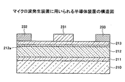
本実施の形態においては、マイクロ波発生部30は、高い出力のマイクロ波を発生させるため、半導体素子、具体的には、窒化物半導体を用いたHEMT等が用いられている。窒化物半導体を用いたHEMTは、図2に示されるように、SiC等の基板210の上に、窒化物半導体層を積層することにより形成されている。即ち、基板210の上に、AlNやGaN等により形成されたバッファ層211、電子走行層212、電子供給層213が順に積層されている。電子走行層212は、GaNにより形成されており、電子供給層213は、AlGaNまたはInAlNにより形成されている。これにより、電子走行層212において、電子供給層213との界面近傍には2DEG212aが生成される。ゲート電極231、ソース電極232、ドレイン電極233は、電子供給層213の上に形成される。
In the present embodiment, the
(マイクロ波加熱装置及び排気浄化装置の制御)
次に、本実施の形態におけるマイクロ波加熱装置及び排気浄化装置の制御について、図3に基づき説明する。尚、本実施の形態におけるマイクロ波加熱装置及び排気浄化装置の制御は、制御部80により行われる。
(Control of microwave heating device and exhaust purification device)
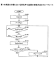
Next, control of the microwave heating device and the exhaust purification device in the present embodiment will be described with reference to FIG. The control of the microwave heating device and the exhaust gas purification device in the present embodiment is performed by the
最初に、ステップ102(S102)において、マイクロ波発生部30において発生されるマイクロ波のパワーを0にする。即ち、マイクロ波発生部30から筐体部20に入射する入射波のパワー(Pin0)を0にする。既に、マイクロ波発生部30から筐体部20に入射する入射波のパワー(Pin0)が0である場合には、その状態が保たれる。
First, in step 102 (S102), the power of the microwave generated by the
次に、ステップ104(S104)において、電磁波発生部41において、電磁波を発生させ、電磁波発生部41から筐体部20内に実際に出力されるパワー(P1)を所定のパワー(Pex1)にする。
Next, in step 104 (S104), the electromagnetic
次に、ステップ106(S106)において、温度測定部70において、微粒子捕集部10の温度Tを測定し、温度測定部70において測定された温度Tが、温度Ta以上、温度Tb以下の温度範囲内であるか否かが判断される。温度Tが、温度Ta以上、温度Tb以下の温度範囲内である場合には、ステップ108に移行し、温度Tが、温度Ta以上、温度Tb以下の温度範囲内でにはない場合には、ステップ106を繰り返す。微粒子捕集部10の温度Tが、温度Ta未満の低温の場合には、マイクロ波を照射しても、所望の温度とはならず、微粒子捕集部10の再生できない。また、微粒子捕集部10の温度Tが、温度Tbを超える高温の場合には、マイクロ波を照射しなくとも、微粒子捕集部10の再生が行われる。このため、微粒子捕集部10の温度Tが、温度Ta以上、温度Tb以下の温度範囲内であるか否かの判断を行う。
Next, in step 106 (S106), the
次に、ステップ108(S108)において、微粒子捕集部10におけるPM等の微粒子の堆積量Mpが、所定の堆積量Maを超えるか否かが判断される。微粒子捕集部10におけるPM等の微粒子の堆積量Mpが、所定のPM等の微粒子の堆積量Maを超えていない場合には、微粒子捕集部10の再生を行う必要がないからである。微粒子捕集部10におけるPM等の微粒子の堆積量Mpが、所定の堆積量Maを超える場合には、ステップ110に移行し、所定の堆積量Ma以下である場合には、ステップ106に移行する。尚、微粒子捕集部10におけるPM等の微粒子の堆積量Mpは、電磁波発生部41において発生させた電磁波を第1の電磁波センサ51と第2の電磁波センサ52により測定し、得られたパワーP1及びP2から、上記の(1)に示す式より算出することができる。
Next, in step 108 (S108), it is determined whether or not the deposition amount Mp of particulates such as PM in the
次に、ステップ110(S110)において、マイクロ波発生部30においてマイクロ波を発生させて、マイクロ波発生部30から筐体部20に入射する入射波のパワー(Pin0)を所定のパワー(Pex0)にする。これにより、微粒子捕集部10の再生が開始する。
Next, in step 110 (S110), the
次に、ステップ112(S112)において、マイクロ波発生部30から筐体部20内に実際に出力されるパワー(P0)が、b×Pin0以下であるか否かが判断される。尚、bは係数である。マイクロ波発生部30から筐体部20内に実際に出力されるパワー(P0)が、b×Pin0以下である場合には、マイクロ波の反射波(Pr0)の割合が多いため、チューナー60においてPr0が低くなるようにチューニングを行う必要がある。マイクロ波発生部30から筐体部20内に実際に出力されるパワー(P0)が、b×Pin0以下である場合にはステップ114に移行し、b×Pin0を超えている場合にはステップ106に移行する。
Next, in step 112 (S112), it is determined whether or not the power (P0) actually output from the
次に、ステップ114(S114)において、チューナー60においてPr0が低くなるようにチューニングを行う。チューナー60においてチューニングを行った後は、ステップ106に移行する。
Next, in step 114 (S114), the
尚、本実施の形態は、電磁波発生部41において発生させた電磁波の反射波を考慮しなくてもよい場合や反射波が殆ど生じない場合には、第1の電磁波センサ51を設けることなく、第2の電磁波センサ52に相当する電磁波センサを1つ設けたものであってもよい。
In the present embodiment, when it is not necessary to consider the reflected wave of the electromagnetic wave generated in the electromagnetic
本実施の形態における排気浄化装置を排気量が3Lのディーゼルエンジンに搭載し、市街地を8時間走行した場合について検討を行った。この場合、発明者の経験より、マイクロ波加熱装置が搭載されていない排気浄化装置と比べ、微粒子捕集部10におけるPM等の微粒子の堆積量を1/3にすることができるものと推察される。また、本実施の形態におけるマイクロ波加熱装置は、食品を加熱する食品加熱装置や化学反応装置等においても用いることが可能である。
The case where the exhaust emission control device according to the present embodiment was mounted on a diesel engine with a displacement of 3 L and traveled in an urban area for 8 hours was examined. In this case, from the experience of the inventor, it is estimated that the amount of particulates such as PM in the
〔第2の実施の形態〕
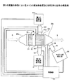
次に、第2の実施の形態について説明する。本実施の形態は、電磁波発生部が複数設けられているマイクロ波加熱装置及び排気浄化装置である。本実施の形態におけるマイクロ波加熱装置及び排気浄化装置について図4に基づき説明する。
[Second Embodiment]
Next, a second embodiment will be described. The present embodiment is a microwave heating device and an exhaust purification device provided with a plurality of electromagnetic wave generators. A microwave heating device and an exhaust purification device in the present embodiment will be described with reference to FIG.
図4に示されるように、本実施の形態における排気浄化装置は、第1の電磁波発生部141、第2の電磁波発生部142、第1の電磁波センサ151、第2の電磁波センサ152等を有している。尚、本実施の形態における排気浄化装置には、第1の実施の形態における排気浄化装置と同様に、微粒子捕集部10、酸化触媒部11、筐体部20、マイクロ波発生部30、マイクロ波センサ50、温度測定部70、制御部80等も設けられている。
As shown in FIG. 4, the exhaust emission control device according to the present embodiment includes a first electromagnetic wave generation unit 141, a second electromagnetic
本実施の形態における第1の電磁波発生部141及び第2の電磁波発生部142は、第1の実施の形態における電磁波発生部41と同様のものであり、発生させる電磁波の周波数は異なっていてもよく、また、同じであってもよい。また、第1の電磁波センサ151及び第2の電磁波センサ152は、第1の実施の形態における第1の電磁波センサ51及び第2の電磁波センサ52と同様に、微粒子捕集部10を介し対向する位置の筐体部20に取り付けられている。
The first electromagnetic wave generation unit 141 and the second electromagnetic
第1の電磁波発生部141と第1の電磁波センサ151との間にはチューナー161が設けられており、第2の電磁波発生部142と第2の電磁波センサ152との間にはチューナー162が設けられている。チューナー161及びチューナー162は、第1の実施の形態におけるチューナー61と同様の機能を有している。即ち、チューナー161は、第1の電磁波発生部141において発生させた電磁波の反射波が低くなるようにチューニングを行い、チューナー162は、第2の電磁波発生部142において発生させた電磁波の反射波が低くなるようにチューニングを行う。
A
本実施の形態では、第1の電磁波センサ151は、第1の電磁波発生部141において発生させた電磁波の入射波と反射波を測定するとともに、第2の電磁波発生部142より筐体部20内に入射し、微粒子捕集部10を透過した電磁波を測定する。また、第2の電磁波センサ152は、第2の電磁波発生部142において発生させた電磁波の入射波と反射波を測定するとともに、第1の電磁波発生部141より筐体部20内に入射し、微粒子捕集部10を透過した電磁波を測定する。
In the present embodiment, the first
制御部80では、第1の電磁波センサ151及び第2の電磁波センサ152において得られた情報に基づき、微粒子捕集部10に堆積しているPM等の微粒子の堆積量Mpを算出する。本実施の形態においては、複数の電磁波発生部を設けることにより、より正確に微粒子捕集部10に堆積しているPM等の微粒子の堆積量Mpを算出することができる。
The
本実施の形態における排気浄化装置においては、第1の電磁波発生部141及び第2の電磁波発生部142に対応する第1の電磁波センサ及び第2の電磁波センサを各々個別に設けてもよい。即ち、第1の電磁波発生部141に対応する第1の電磁波センサ及び第2の電磁波センサと、第2の電磁波発生部142に対応する第1の電磁波センサ及び第2の電磁波センサとを設けてもよい。この場合、電磁波センサは、合わせて4つとなる。
In the exhaust emission control device according to the present embodiment, the first electromagnetic wave sensor and the second electromagnetic wave sensor corresponding to the first electromagnetic wave generation unit 141 and the second electromagnetic
本実施の形態においては、第1の電磁波発生部141において発生させた電磁波と第2の電磁波発生部142において発生させた電磁波の周波数が異なる場合には、電磁波を連続して発生させることができる。また、第1の電磁波発生部141において発生させた電磁波と第2の電磁波発生部142において発生させた電磁波の周波数が同じである場合には、発生させる電磁波のタイミングをずらし、交互に発生させてもよい。
In the present embodiment, when the frequency of the electromagnetic wave generated in the first electromagnetic wave generation unit 141 is different from the frequency of the electromagnetic wave generated in the second electromagnetic
尚、上記外の内容については、第1の実施の形態と同様である。 The contents other than the above are the same as those in the first embodiment.
以上、実施の形態について詳述したが、特定の実施形態に限定されるものではなく、特許請求の範囲に記載された範囲内において、種々の変形及び変更が可能である。 Although the embodiment has been described in detail above, it is not limited to the specific embodiment, and various modifications and changes can be made within the scope described in the claims.
上記の説明に関し、更に以下の付記を開示する。
(付記1)
被加熱物が入れられる筐体部と、
マイクロ波を発生させるマイクロ波発生部と、
前記マイクロ波とは異なる周波数の電磁波を発生させる電磁波発生部と、
前記電磁波発生部より前記筐体部に入射し、前記被加熱物を透過した電磁波のパワーを測定する電磁波センサと、
前記電磁波センサにおいて検出された電磁波のパワーに基づき、前記マイクロ波発生部におけるマイクロ波の発生を制御する制御部と、
を有することを特徴とするマイクロ波加熱装置。
(付記2)
前記電磁波発生部において発生させる電磁波は、前記マイクロ波よりも周波数が高いことを特徴とする付記1に記載のマイクロ波加熱装置。
(付記3)
被加熱物が入れられる筐体部と、
マイクロ波を発生させるマイクロ波発生部と、
前記マイクロ波とは異なる周波数の電磁波を発生させる電磁波発生部と、
前記電磁波発生部より前記筐体部に入射する電磁波のパワーを測定する第1の電磁波センサと、
前記電磁波発生部より前記筐体部に入射し、前記被加熱物を透過した電磁波のパワーを測定する第2の電磁波センサと、
前記第1の電磁波センサにおいて検出された電磁波のパワーと、前記第2の電磁波センサにおいて検出された電磁波のパワーに基づき、前記マイクロ波発生部におけるマイクロ波の発生を制御する制御部と、
を有することを特徴とするマイクロ波加熱装置。
(付記4)
前記電磁波発生部において発生させる電磁波は、前記マイクロ波よりも周波数が高いことを特徴とする請求項3に記載のマイクロ波加熱装置。
(付記5)
前記電磁波発生部において発生させる電磁波は、10GHz以上、10THz以下の電磁波であることを特徴とする付記1から4のいずれかに記載のマイクロ波加熱装置。
(付記6)
前記電磁波発生部は複数設けられていることを特徴とする付記1から5のいずれかに記載のマイクロ波加熱装置。
(付記7)
前記被加熱物の温度を測定する温度測定部を有し、
前記制御部は、前記温度測定部において測定した温度が、所定の温度範囲の場合には、前記マイクロ波発生部においてマイクロ波を発生させる制御を行うことを特徴とする付記1から6のいずれかに記載のマイクロ波加熱装置。
(付記8)
前記マイクロ波発生部において発生させたマイクロ波が、前記筐体部に入射する入射波のパワーと反射波のパワーとを測定するマイクロ波センサが設けられており、
前記マイクロ波センサにおいて測定された前記入射波のパワーと前記反射波のパワーに基づき、前記反射波のパワーが低くなるようなチューニングを行うチューナーが設けられていることを特徴とする付記1から7のいずれかに記載のマイクロ波加熱装置。
(付記9)
マイクロ波発生部は、窒化物半導体により形成された半導体素子を含むものであることを特徴とする付記1から8のいずれかに記載のマイクロ波加熱装置。
(付記10)
付記1から9のいずれかに記載のマイクロ波加熱装置と、
排気に含まれる微粒子を捕集する微粒子捕集部と、
を有し、
前記微粒子捕集部が前記被加熱物であって、
前記筐体部は、前記微粒子捕集部を覆う筐体本体部と、前記筐体本体部に接続されている前記排気の吸入口及び排出口が設けられており、
前記微粒子捕集部には、前記マイクロ波加熱装置からマイクロ波が照射されることを特徴とする排気浄化装置。
(付記11)
付記3または4に記載のマイクロ波加熱装置と、
排気に含まれる微粒子を捕集する微粒子捕集部と、
を有し、
前記微粒子捕集部が前記被加熱物であって、
前記筐体部は、前記微粒子捕集部を覆う筐体本体部と、前記筐体本体部に接続されている前記排気の吸入口及び排出口が設けられており、
前記制御部は、前記第1の電磁波センサにおいて検出された電磁波のパワーと、前記第2の電磁波センサにおいて検出された電磁波のパワーに基づき前記微粒子捕集部に堆積している微粒子の堆積量を算出し、前記微粒子の堆積量が所定の堆積量以上である場合には、前記マイクロ波発生部においてマイクロ波を発生する制御を行うことを特徴とする排気浄化装置。
(付記12)
前記電磁波発生部において発生させる電磁波は、10GHz以上、10THz以下の電磁波であることを特徴とする付記11に記載の排気浄化装置。
(付記13)
前記被加熱物の温度を測定する温度測定部が設けられており、
前記制御部は、前記温度測定部において測定した温度が、所定の温度範囲の場合には、前記マイクロ波発生部においてマイクロ波を発生させる制御を行うことを特徴とする付記11または12に記載の排気浄化装置。
In addition to the above description, the following additional notes are disclosed.
(Appendix 1)
A housing part to be heated, and
A microwave generator for generating microwaves;
An electromagnetic wave generator that generates an electromagnetic wave having a frequency different from that of the microwave;
An electromagnetic wave sensor that measures the power of an electromagnetic wave that is incident on the casing from the electromagnetic wave generator and passes through the object to be heated;
Based on the power of the electromagnetic wave detected by the electromagnetic wave sensor, a control unit for controlling the generation of the microwave in the microwave generation unit,
A microwave heating apparatus comprising:
(Appendix 2)
The microwave heating apparatus according to appendix 1, wherein the electromagnetic wave generated in the electromagnetic wave generation unit has a frequency higher than that of the microwave.
(Appendix 3)
A housing part to be heated, and
A microwave generator for generating microwaves;
An electromagnetic wave generator that generates an electromagnetic wave having a frequency different from that of the microwave;
A first electromagnetic wave sensor that measures the power of an electromagnetic wave incident on the housing from the electromagnetic wave generator;
A second electromagnetic wave sensor that measures the power of an electromagnetic wave incident on the casing from the electromagnetic wave generator and transmitted through the object to be heated;
A control unit that controls generation of microwaves in the microwave generation unit based on the power of the electromagnetic waves detected in the first electromagnetic wave sensor and the power of the electromagnetic waves detected in the second electromagnetic wave sensor;
A microwave heating apparatus comprising:
(Appendix 4)
The microwave heating device according to claim 3, wherein the electromagnetic wave generated in the electromagnetic wave generation unit has a higher frequency than the microwave.
(Appendix 5)
The microwave heating device according to any one of appendices 1 to 4, wherein the electromagnetic wave generated in the electromagnetic wave generation unit is an electromagnetic wave of 10 GHz or more and 10 THz or less.
(Appendix 6)
The microwave heating apparatus according to any one of appendices 1 to 5, wherein a plurality of the electromagnetic wave generating units are provided.
(Appendix 7)
A temperature measuring unit for measuring the temperature of the object to be heated;
The control unit performs control to generate a microwave in the microwave generation unit when the temperature measured in the temperature measurement unit is in a predetermined temperature range. A microwave heating apparatus according to 1.
(Appendix 8)
A microwave sensor that measures the power of the incident wave and the power of the reflected wave incident on the casing by the microwave generated by the microwave generation unit is provided,
Additional notes 1 to 7 characterized in that a tuner is provided that performs tuning such that the power of the reflected wave is low based on the power of the incident wave and the power of the reflected wave measured by the microwave sensor. The microwave heating device according to any one of the above.
(Appendix 9)
9. The microwave heating apparatus according to any one of appendices 1 to 8, wherein the microwave generation unit includes a semiconductor element formed of a nitride semiconductor.
(Appendix 10)
The microwave heating device according to any one of appendices 1 to 9,
A particulate collection unit for collecting particulates contained in the exhaust;
Have
The particulate collection part is the object to be heated,
The housing part is provided with a housing body part that covers the particulate collection part, and an exhaust inlet and an exhaust port connected to the housing body part,
The exhaust gas purification apparatus, wherein the particulate collection unit is irradiated with microwaves from the microwave heating apparatus.
(Appendix 11)
The microwave heating apparatus according to appendix 3 or 4,
A particulate collection unit for collecting particulates contained in the exhaust;
Have
The particulate collection part is the object to be heated,
The housing part is provided with a housing body part that covers the particulate collection part, and an exhaust inlet and an exhaust port connected to the housing body part,
The control unit is configured to determine a deposition amount of the fine particles accumulated in the fine particle collecting unit based on the power of the electromagnetic wave detected by the first electromagnetic wave sensor and the power of the electromagnetic wave detected by the second electromagnetic wave sensor. An exhaust emission control device that performs control to generate microwaves in the microwave generation unit when the amount of accumulated particulate matter is equal to or greater than a predetermined accumulation amount.
(Appendix 12)
The exhaust emission control device according to
(Appendix 13)
A temperature measuring unit for measuring the temperature of the object to be heated is provided;
The control unit performs control to generate a microwave in the microwave generation unit when the temperature measured in the temperature measurement unit is in a predetermined temperature range. Exhaust purification device.
10 微粒子捕集部
11 酸化触媒部
20 筐体部
20a 筐体本体部
20b 吸入口
20c 排出口
30 マイクロ波発生部
41 電磁波発生部
50 マイクロ波センサ
51 第1の電磁波センサ
52 第2の電磁波センサ
60 チューナー
61 チューナー
70 温度測定部
80 制御部
DESCRIPTION OF
Claims (8)
マイクロ波を発生させるマイクロ波発生部と、
前記マイクロ波とは異なる周波数の電磁波を発生させる電磁波発生部と、
前記電磁波発生部より前記筐体部に入射し、前記被加熱物を透過した電磁波のパワーを測定する電磁波センサと、
前記電磁波センサにおいて検出された電磁波のパワーに基づき、前記マイクロ波発生部におけるマイクロ波の発生を制御する制御部と、
を有することを特徴とするマイクロ波加熱装置。 A housing part to be heated, and
A microwave generator for generating microwaves;
An electromagnetic wave generator that generates an electromagnetic wave having a frequency different from that of the microwave;
An electromagnetic wave sensor that measures the power of an electromagnetic wave that is incident on the casing from the electromagnetic wave generator and passes through the object to be heated;
Based on the power of the electromagnetic wave detected by the electromagnetic wave sensor, a control unit for controlling the generation of the microwave in the microwave generation unit,
A microwave heating apparatus comprising:
マイクロ波を発生させるマイクロ波発生部と、
前記マイクロ波とは異なる周波数の電磁波を発生させる電磁波発生部と、
前記電磁波発生部より前記筐体部に入射する電磁波のパワーを測定する第1の電磁波センサと、
前記電磁波発生部より前記筐体部に入射し、前記被加熱物を透過した電磁波のパワーを測定する第2の電磁波センサと、
前記第1の電磁波センサにおいて検出された電磁波のパワーと、前記第2の電磁波センサにおいて検出された電磁波のパワーに基づき、前記マイクロ波発生部におけるマイクロ波の発生を制御する制御部と、
を有することを特徴とするマイクロ波加熱装置。 A housing part to be heated, and
A microwave generator for generating microwaves;
An electromagnetic wave generator that generates an electromagnetic wave having a frequency different from that of the microwave;
A first electromagnetic wave sensor that measures the power of an electromagnetic wave incident on the housing from the electromagnetic wave generator;
A second electromagnetic wave sensor that measures the power of an electromagnetic wave incident on the casing from the electromagnetic wave generator and transmitted through the object to be heated;
A control unit that controls generation of microwaves in the microwave generation unit based on the power of the electromagnetic waves detected in the first electromagnetic wave sensor and the power of the electromagnetic waves detected in the second electromagnetic wave sensor;
A microwave heating apparatus comprising:
排気に含まれる微粒子を捕集する微粒子捕集部と、
を有し、
前記微粒子捕集部が前記被加熱物であって、
前記筐体部は、前記微粒子捕集部を覆う筐体本体部と、前記筐体本体部に接続されている前記排気の吸入口及び排出口が設けられており、
前記微粒子捕集部には、前記マイクロ波加熱装置からマイクロ波が照射されることを特徴とする排気浄化装置。 A microwave heating device according to any one of claims 1 to 6;
A particulate collection unit for collecting particulates contained in the exhaust;
Have
The particulate collection part is the object to be heated,
The housing part is provided with a housing body part that covers the particulate collection part, and an exhaust inlet and an exhaust port connected to the housing body part,
The exhaust gas purification apparatus, wherein the particulate collection unit is irradiated with microwaves from the microwave heating apparatus.
排気に含まれる微粒子を捕集する微粒子捕集部と、
を有し、
前記微粒子捕集部が前記被加熱物であって、
前記筐体部は、前記微粒子捕集部を覆う筐体本体部と、前記筐体本体部に接続されている前記排気の吸入口及び排出口が設けられており、
前記制御部は、前記第1の電磁波センサにおいて検出された電磁波のパワーと、前記第2の電磁波センサにおいて検出された電磁波のパワーに基づき前記微粒子捕集部に堆積している微粒子の堆積量を算出し、前記微粒子の堆積量が所定の堆積量以上である場合には、前記マイクロ波発生部においてマイクロ波を発生する制御を行うことを特徴とする排気浄化装置。 A microwave heating device according to claim 3 or 4,
A particulate collection unit for collecting particulates contained in the exhaust;
Have
The particulate collection part is the object to be heated,
The housing part is provided with a housing body part that covers the particulate collection part, and an exhaust inlet and an exhaust port connected to the housing body part,
The control unit is configured to determine a deposition amount of the particulates deposited on the particulate collection unit based on the electromagnetic wave power detected by the first electromagnetic wave sensor and the electromagnetic wave power detected by the second electromagnetic wave sensor. An exhaust emission control device that performs control to generate microwaves in the microwave generation unit when the amount of accumulated particulate matter is equal to or greater than a predetermined accumulation amount.
Priority Applications (2)
| Application Number | Priority Date | Filing Date | Title |
|---|---|---|---|
| JP2016079489A JP6733275B2 (en) | 2016-04-12 | 2016-04-12 | Microwave heating device and exhaust gas purification device |
| US15/471,109 US10577992B2 (en) | 2016-04-12 | 2017-03-28 | Microwave heating apparatus and exhaust gas purification apparatus |
Applications Claiming Priority (1)
| Application Number | Priority Date | Filing Date | Title |
|---|---|---|---|
| JP2016079489A JP6733275B2 (en) | 2016-04-12 | 2016-04-12 | Microwave heating device and exhaust gas purification device |
Publications (2)
| Publication Number | Publication Date |
|---|---|
| JP2017191671A true JP2017191671A (en) | 2017-10-19 |
| JP6733275B2 JP6733275B2 (en) | 2020-07-29 |
Family
ID=59999301
Family Applications (1)
| Application Number | Title | Priority Date | Filing Date |
|---|---|---|---|
| JP2016079489A Expired - Fee Related JP6733275B2 (en) | 2016-04-12 | 2016-04-12 | Microwave heating device and exhaust gas purification device |
Country Status (2)
| Country | Link |
|---|---|
| US (1) | US10577992B2 (en) |
| JP (1) | JP6733275B2 (en) |
Families Citing this family (6)
| Publication number | Priority date | Publication date | Assignee | Title |
|---|---|---|---|---|
| US20190381455A1 (en) * | 2017-01-13 | 2019-12-19 | Panasonic Corporation | Catalyst heating device and heating device |
| JP6880848B2 (en) * | 2017-03-10 | 2021-06-02 | 富士通株式会社 | Microwave irradiation equipment, exhaust gas purification equipment, automobiles and management systems |
| JP6881363B2 (en) * | 2018-03-16 | 2021-06-02 | トヨタ自動車株式会社 | Abnormality diagnostic device |
| JP6828706B2 (en) * | 2018-03-22 | 2021-02-10 | トヨタ自動車株式会社 | Internal combustion engine exhaust purification system |
| WO2020084934A1 (en) * | 2018-10-26 | 2020-04-30 | 富士電機株式会社 | Electric dust collector |
| CN111412036A (en) * | 2020-04-22 | 2020-07-14 | 扬州工业职业技术学院 | Method for trapping and regenerating engine exhaust particles |
Citations (3)
| Publication number | Priority date | Publication date | Assignee | Title |
|---|---|---|---|---|
| JPH05263622A (en) * | 1992-02-03 | 1993-10-12 | Riken Corp | Method and apparatus for detecting amount of particle material trapped in exhaust gas filter in diesel engine |
| JPH0783022A (en) * | 1993-09-20 | 1995-03-28 | Matsushita Electric Ind Co Ltd | Filter regeneration device for internal combustion engine |
| JP2009057948A (en) * | 2007-09-03 | 2009-03-19 | Toyota Motor Corp | Particulate matter collection distribution detection method, collection distribution detection device and exhaust gas purification device |
Family Cites Families (9)
| Publication number | Priority date | Publication date | Assignee | Title |
|---|---|---|---|---|
| JPH06307224A (en) | 1993-04-22 | 1994-11-01 | Toyota Motor Corp | Exhaust particulate purifying device |
| JPH07145720A (en) | 1993-11-22 | 1995-06-06 | Matsushita Electric Ind Co Ltd | Filter regeneration device for internal combustion engine |
| JP3800649B2 (en) | 1995-10-24 | 2006-07-26 | 松下電器産業株式会社 | Filter regeneration device for internal combustion engine |
| JPH10220219A (en) | 1997-02-03 | 1998-08-18 | Matsushita Electric Ind Co Ltd | Exhaust gas purification device |
| ATE354268T1 (en) * | 1998-12-17 | 2007-03-15 | Biotage Ab | MICROWAVE APPARATUS AND METHOD FOR CARRYING OUT CHEMICAL REACTIONS |
| JP2006140063A (en) | 2004-11-12 | 2006-06-01 | Toyota Central Res & Dev Lab Inc | Microwave heating method and microwave heating apparatus |
| JP5163695B2 (en) | 2010-05-31 | 2013-03-13 | 株式会社デンソー | Exhaust gas purification device for internal combustion engine |
| JP5738814B2 (en) * | 2012-09-12 | 2015-06-24 | 株式会社東芝 | Microwave annealing apparatus and semiconductor device manufacturing method |
| TWI568316B (en) * | 2015-11-05 | 2017-01-21 | 財團法人工業技術研究院 | Multiple mode microwave heating device |
-
2016
- 2016-04-12 JP JP2016079489A patent/JP6733275B2/en not_active Expired - Fee Related
-
2017
- 2017-03-28 US US15/471,109 patent/US10577992B2/en active Active
Patent Citations (3)
| Publication number | Priority date | Publication date | Assignee | Title |
|---|---|---|---|---|
| JPH05263622A (en) * | 1992-02-03 | 1993-10-12 | Riken Corp | Method and apparatus for detecting amount of particle material trapped in exhaust gas filter in diesel engine |
| JPH0783022A (en) * | 1993-09-20 | 1995-03-28 | Matsushita Electric Ind Co Ltd | Filter regeneration device for internal combustion engine |
| JP2009057948A (en) * | 2007-09-03 | 2009-03-19 | Toyota Motor Corp | Particulate matter collection distribution detection method, collection distribution detection device and exhaust gas purification device |
Also Published As
| Publication number | Publication date |
|---|---|
| JP6733275B2 (en) | 2020-07-29 |
| US10577992B2 (en) | 2020-03-03 |
| US20170292420A1 (en) | 2017-10-12 |
Similar Documents
| Publication | Publication Date | Title |
|---|---|---|
| JP6733275B2 (en) | Microwave heating device and exhaust gas purification device | |
| CN101680323B (en) | Method for detecting capture amount of particulate matter, detection device for capture amount, and exhaust gas purification device | |
| JP6682870B2 (en) | Microwave irradiation device, exhaust gas purification device, heating device and chemical reaction device | |
| JP5562073B2 (en) | Particulate matter accumulation detection device | |
| JP6855884B2 (en) | Exhaust purification equipment, internal combustion equipment, power generation equipment and automobiles | |
| JP2010249126A (en) | Particulate matter accumulation detection device | |
| JP4949976B2 (en) | Particulate matter collection distribution detection method, collection distribution detection device and exhaust gas purification device | |
| US10850221B2 (en) | Fine particle detector and exhaust gas purification apparatus | |
| JP5060368B2 (en) | Particulate matter collection amount detection method, collection amount detection device and exhaust gas purification device | |
| JPWO2011118669A1 (en) | Method for detecting particulate matter | |
| CN103620169B (en) | Particulate collection filter state detection device | |
| JP2011137445A (en) | Method and device for detecting accumulation amount of particulate matter | |
| JP2010271303A (en) | Method and device for detecting deposition amount of particulate matter | |
| JP2010223169A (en) | Accumulation amount detection device for particulate | |
| JP2018204451A (en) | Particulate detector and exhaust emission control device | |
| JP2018053793A (en) | Filter regeneration device, filter clogging detection device, exhaust gas processing device, and filter clogging determination method | |
| JP4385850B2 (en) | Collection amount detection method and collection amount detection device | |
| JP2010223165A (en) | Accumulation amount detection device for particulate | |
| JP6699187B2 (en) | Exhaust gas purification device | |
| US20150300226A1 (en) | Em energy application for treating exhaust gases | |
| JP2738307B2 (en) | Particulate collection weight determination device | |
| RU2757745C1 (en) | Device for determining concentration of exhaust gases in gas duct of diesel vehicles and cleaning from gases | |
| JP7267900B2 (en) | Particulate matter measuring device, particulate matter measuring method, and particulate matter measuring program | |
| JP6551095B2 (en) | Exhaust purification device |
Legal Events
| Date | Code | Title | Description |
|---|---|---|---|
| A621 | Written request for application examination |
Free format text: JAPANESE INTERMEDIATE CODE: A621 Effective date: 20190115 |
|
| A977 | Report on retrieval |
Free format text: JAPANESE INTERMEDIATE CODE: A971007 Effective date: 20191121 |
|
| A131 | Notification of reasons for refusal |
Free format text: JAPANESE INTERMEDIATE CODE: A131 Effective date: 20191224 |
|
| A521 | Request for written amendment filed |
Free format text: JAPANESE INTERMEDIATE CODE: A523 Effective date: 20200214 |
|
| TRDD | Decision of grant or rejection written | ||
| A01 | Written decision to grant a patent or to grant a registration (utility model) |
Free format text: JAPANESE INTERMEDIATE CODE: A01 Effective date: 20200609 |
|
| A61 | First payment of annual fees (during grant procedure) |
Free format text: JAPANESE INTERMEDIATE CODE: A61 Effective date: 20200622 |
|
| R150 | Certificate of patent or registration of utility model |
Ref document number: 6733275 Country of ref document: JP Free format text: JAPANESE INTERMEDIATE CODE: R150 |
|
| LAPS | Cancellation because of no payment of annual fees |