JP2017191907A - Fiber laser oscillator and clean bench mounted on the same - Google Patents
Fiber laser oscillator and clean bench mounted on the same Download PDFInfo
- Publication number
- JP2017191907A JP2017191907A JP2016082100A JP2016082100A JP2017191907A JP 2017191907 A JP2017191907 A JP 2017191907A JP 2016082100 A JP2016082100 A JP 2016082100A JP 2016082100 A JP2016082100 A JP 2016082100A JP 2017191907 A JP2017191907 A JP 2017191907A
- Authority
- JP
- Japan
- Prior art keywords
- clean bench
- housing
- laser oscillator
- fiber laser
- optical unit
- Prior art date
- Legal status (The legal status is an assumption and is not a legal conclusion. Google has not performed a legal analysis and makes no representation as to the accuracy of the status listed.)
- Granted
Links
Images

Classifications
-
- H—ELECTRICITY
- H01—ELECTRIC ELEMENTS
- H01S—DEVICES USING THE PROCESS OF LIGHT AMPLIFICATION BY STIMULATED EMISSION OF RADIATION [LASER] TO AMPLIFY OR GENERATE LIGHT; DEVICES USING STIMULATED EMISSION OF ELECTROMAGNETIC RADIATION IN WAVE RANGES OTHER THAN OPTICAL
- H01S3/00—Lasers, i.e. devices using stimulated emission of electromagnetic radiation in the infrared, visible or ultraviolet wave range
- H01S3/05—Construction or shape of optical resonators; Accommodation of active medium therein; Shape of active medium
- H01S3/06—Construction or shape of active medium
- H01S3/063—Waveguide lasers, i.e. whereby the dimensions of the waveguide are of the order of the light wavelength
- H01S3/067—Fibre lasers
- H01S3/06704—Housings; Packages
-
- B—PERFORMING OPERATIONS; TRANSPORTING
- B23—MACHINE TOOLS; METAL-WORKING NOT OTHERWISE PROVIDED FOR
- B23K—SOLDERING OR UNSOLDERING; WELDING; CLADDING OR PLATING BY SOLDERING OR WELDING; CUTTING BY APPLYING HEAT LOCALLY, e.g. FLAME CUTTING; WORKING BY LASER BEAM
- B23K26/00—Working by laser beam, e.g. welding, cutting or boring
- B23K26/02—Positioning or observing the workpiece, e.g. with respect to the point of impact; Aligning, aiming or focusing the laser beam
- B23K26/03—Observing, e.g. monitoring, the workpiece
-
- B—PERFORMING OPERATIONS; TRANSPORTING
- B23—MACHINE TOOLS; METAL-WORKING NOT OTHERWISE PROVIDED FOR
- B23K—SOLDERING OR UNSOLDERING; WELDING; CLADDING OR PLATING BY SOLDERING OR WELDING; CUTTING BY APPLYING HEAT LOCALLY, e.g. FLAME CUTTING; WORKING BY LASER BEAM
- B23K26/00—Working by laser beam, e.g. welding, cutting or boring
- B23K26/02—Positioning or observing the workpiece, e.g. with respect to the point of impact; Aligning, aiming or focusing the laser beam
- B23K26/06—Shaping the laser beam, e.g. by masks or multi-focusing
- B23K26/062—Shaping the laser beam, e.g. by masks or multi-focusing by direct control of the laser beam
-
- B—PERFORMING OPERATIONS; TRANSPORTING
- B23—MACHINE TOOLS; METAL-WORKING NOT OTHERWISE PROVIDED FOR
- B23K—SOLDERING OR UNSOLDERING; WELDING; CLADDING OR PLATING BY SOLDERING OR WELDING; CUTTING BY APPLYING HEAT LOCALLY, e.g. FLAME CUTTING; WORKING BY LASER BEAM
- B23K26/00—Working by laser beam, e.g. welding, cutting or boring
- B23K26/12—Working by laser beam, e.g. welding, cutting or boring in a special environment or atmosphere, e.g. in an enclosure
- B23K26/127—Working by laser beam, e.g. welding, cutting or boring in a special environment or atmosphere, e.g. in an enclosure in an enclosure
-
- B—PERFORMING OPERATIONS; TRANSPORTING
- B23—MACHINE TOOLS; METAL-WORKING NOT OTHERWISE PROVIDED FOR
- B23K—SOLDERING OR UNSOLDERING; WELDING; CLADDING OR PLATING BY SOLDERING OR WELDING; CUTTING BY APPLYING HEAT LOCALLY, e.g. FLAME CUTTING; WORKING BY LASER BEAM
- B23K26/00—Working by laser beam, e.g. welding, cutting or boring
- B23K26/352—Working by laser beam, e.g. welding, cutting or boring for surface treatment
-
- B—PERFORMING OPERATIONS; TRANSPORTING
- B23—MACHINE TOOLS; METAL-WORKING NOT OTHERWISE PROVIDED FOR
- B23K—SOLDERING OR UNSOLDERING; WELDING; CLADDING OR PLATING BY SOLDERING OR WELDING; CUTTING BY APPLYING HEAT LOCALLY, e.g. FLAME CUTTING; WORKING BY LASER BEAM
- B23K26/00—Working by laser beam, e.g. welding, cutting or boring
- B23K26/36—Removing material
- B23K26/38—Removing material by boring or cutting
-
- H—ELECTRICITY
- H01—ELECTRIC ELEMENTS
- H01S—DEVICES USING THE PROCESS OF LIGHT AMPLIFICATION BY STIMULATED EMISSION OF RADIATION [LASER] TO AMPLIFY OR GENERATE LIGHT; DEVICES USING STIMULATED EMISSION OF ELECTROMAGNETIC RADIATION IN WAVE RANGES OTHER THAN OPTICAL
- H01S3/00—Lasers, i.e. devices using stimulated emission of electromagnetic radiation in the infrared, visible or ultraviolet wave range
- H01S3/0014—Monitoring arrangements not otherwise provided for
-
- H—ELECTRICITY
- H01—ELECTRIC ELEMENTS
- H01S—DEVICES USING THE PROCESS OF LIGHT AMPLIFICATION BY STIMULATED EMISSION OF RADIATION [LASER] TO AMPLIFY OR GENERATE LIGHT; DEVICES USING STIMULATED EMISSION OF ELECTROMAGNETIC RADIATION IN WAVE RANGES OTHER THAN OPTICAL
- H01S3/00—Lasers, i.e. devices using stimulated emission of electromagnetic radiation in the infrared, visible or ultraviolet wave range
- H01S3/02—Constructional details
- H01S3/04—Arrangements for thermal management
- H01S3/0407—Liquid cooling, e.g. by water
-
- H—ELECTRICITY
- H01—ELECTRIC ELEMENTS
- H01S—DEVICES USING THE PROCESS OF LIGHT AMPLIFICATION BY STIMULATED EMISSION OF RADIATION [LASER] TO AMPLIFY OR GENERATE LIGHT; DEVICES USING STIMULATED EMISSION OF ELECTROMAGNETIC RADIATION IN WAVE RANGES OTHER THAN OPTICAL
- H01S3/00—Lasers, i.e. devices using stimulated emission of electromagnetic radiation in the infrared, visible or ultraviolet wave range
- H01S3/10—Controlling the intensity, frequency, phase, polarisation or direction of the emitted radiation, e.g. switching, gating, modulating or demodulating
- H01S3/10069—Memorized or pre-programmed characteristics, e.g. look-up table [LUT]
-
- H—ELECTRICITY
- H01—ELECTRIC ELEMENTS
- H01S—DEVICES USING THE PROCESS OF LIGHT AMPLIFICATION BY STIMULATED EMISSION OF RADIATION [LASER] TO AMPLIFY OR GENERATE LIGHT; DEVICES USING STIMULATED EMISSION OF ELECTROMAGNETIC RADIATION IN WAVE RANGES OTHER THAN OPTICAL
- H01S3/00—Lasers, i.e. devices using stimulated emission of electromagnetic radiation in the infrared, visible or ultraviolet wave range
- H01S3/23—Arrangements of two or more lasers not provided for in groups H01S3/02 - H01S3/22, e.g. tandem arrangements of separate active media
- H01S3/2383—Parallel arrangements
-
- H—ELECTRICITY
- H01—ELECTRIC ELEMENTS
- H01S—DEVICES USING THE PROCESS OF LIGHT AMPLIFICATION BY STIMULATED EMISSION OF RADIATION [LASER] TO AMPLIFY OR GENERATE LIGHT; DEVICES USING STIMULATED EMISSION OF ELECTROMAGNETIC RADIATION IN WAVE RANGES OTHER THAN OPTICAL
- H01S3/00—Lasers, i.e. devices using stimulated emission of electromagnetic radiation in the infrared, visible or ultraviolet wave range
- H01S3/02—Constructional details
- H01S3/025—Constructional details of solid state lasers, e.g. housings or mountings
- H01S3/027—Constructional details of solid state lasers, e.g. housings or mountings comprising a special atmosphere inside the housing
-
- H—ELECTRICITY
- H01—ELECTRIC ELEMENTS
- H01S—DEVICES USING THE PROCESS OF LIGHT AMPLIFICATION BY STIMULATED EMISSION OF RADIATION [LASER] TO AMPLIFY OR GENERATE LIGHT; DEVICES USING STIMULATED EMISSION OF ELECTROMAGNETIC RADIATION IN WAVE RANGES OTHER THAN OPTICAL
- H01S3/00—Lasers, i.e. devices using stimulated emission of electromagnetic radiation in the infrared, visible or ultraviolet wave range
- H01S3/02—Constructional details
- H01S3/04—Arrangements for thermal management
- H01S3/0404—Air- or gas cooling, e.g. by dry nitrogen
Landscapes
- Physics & Mathematics (AREA)
- Engineering & Computer Science (AREA)
- Optics & Photonics (AREA)
- Plasma & Fusion (AREA)
- Electromagnetism (AREA)
- Mechanical Engineering (AREA)
- Microelectronics & Electronic Packaging (AREA)
- Lasers (AREA)
- Laser Beam Processing (AREA)
- Ventilation (AREA)
Abstract
Description
本発明は、光ファイバが内部で融着処理によって接続される光学ユニットを備えるファイバレーザ発振器及びこれに搭載可能なクリーンベンチに関する。 The present invention relates to a fiber laser oscillator including an optical unit to which an optical fiber is internally connected by a fusion process, and a clean bench that can be mounted on the fiber laser oscillator.
従来から、光ファイバの融着処理において、クリーンベンチのような作業空間をカバーするものを利用して融着処理が行われることが知られている。この種のファイバレーザ発振器に関する技術を開示するものとして、例えば特許文献1や特許文献2がある。特許文献1には、発振器筐体内から引き出し可能に収納される融着テーブルの内部に光ファイバの融着部が配置される装置について記載されている。また、特許文献2には、光ファイバ接続用作業台の下部にフィルタ付きファンを備え、作業台の上部を透明カバーで覆い、融着接続する装置について記載されている。 2. Description of the Related Art Conventionally, it is known that an optical fiber fusion process is performed using a material that covers a work space such as a clean bench. For example, Patent Document 1 and Patent Document 2 disclose techniques relating to this type of fiber laser oscillator. Patent Document 1 describes an apparatus in which a fusion part of an optical fiber is arranged inside a fusion table that is housed so as to be drawable from the inside of an oscillator housing. Japanese Patent Application Laid-Open No. H10-228561 describes a device that includes a fan with a filter in the lower part of an optical fiber connection work table, covers the upper part of the work table with a transparent cover, and performs fusion splicing.
ファイバレーザ発振器に内蔵される光学ユニットの光ファイバは、工場のクリーンルーム内で融着処理が行われることが一般的である。しかし、融着処理を行うテーブルを隙間なく覆うためには大型のクリーンベンチが必要となり、フィールド現場への持ち運びが困難である。作業台を使うような場合は、設置スペースを確保する必要がある上、作業台まで光ファイバを長く取り回す必要がある。 The optical fiber of the optical unit built in the fiber laser oscillator is generally subjected to a fusion process in a clean room of a factory. However, a large clean bench is required to cover the table to be fused without gaps, making it difficult to carry it to the field site. When using a workbench, it is necessary to secure an installation space and to run an optical fiber long to the workbench.
また、クリーンブース内で融着処理を行うことはできたとしても、光ファイバを取り外したり、光学部品を交換したりすることまでは考慮されていない。そのため、コンバイナテーブル等の光学ユニットを引き出した状態で光学部品を交換すると光学ユニット内部に粉塵が混入したり、コンバイナテーブルを引き出した状態で発振器を立ち上げると結露の発生により光学部品に不具合が生じたりするおそれがあり、保守交換作業及び交換後に光学部品の温度を測定する等の確認作業が難しいものとなっていた。 Even if the fusion process can be performed in the clean booth, no consideration is given to removing an optical fiber or replacing an optical component. For this reason, if the optical parts are replaced with the optical unit such as the combiner table pulled out, dust will be mixed inside the optical unit, or if the oscillator is started up with the combiner table pulled out, dew formation will cause problems with the optical parts. Therefore, it is difficult to perform maintenance and replacement work and confirmation work such as measuring the temperature of the optical component after the replacement.
本発明は、粉塵の侵入及び湿気による光学部品の故障を防止でき、光学ユニットの保守交換及び交換後の確認作業等を良好に行うことができるクリーンベンチ及びこれを搭載したレーザファイバ発振器を提供することを目的とする。 The present invention provides a clean bench capable of preventing optical component failure due to dust intrusion and moisture, and capable of satisfactorily performing maintenance and replacement of the optical unit and confirmation work after replacement, and a laser fiber oscillator equipped with the clean bench. For the purpose.
本発明は、光ファイバが接続される融着接続部を有する光学ユニット(例えば、後述の光学ユニット12)を備えるファイバレーザ発振器(例えば、後述のファイバレーザ発振器10)であって、前記光学ユニットを引き出し可能に収容する筐体(例えば、後述の筐体11)と、前記筐体又は前記光学ユニット側に着脱自在であって、前記筐体から引き出された前記光学ユニットの上方に外部から隔絶された閉鎖空間を形成するクリーンベンチ(例えば、後述のクリーンベンチ20)と、を備え、前記クリーンベンチには、前記筐体の内部空間に連通する連通口(例えば、後述の連通口22)が形成されるファイバレーザ発振器に関する。
The present invention relates to a fiber laser oscillator (for example, a
前記ファイバレーザ発振器は、前記クリーンベンチの内部の湿度を検出する湿度検出部(例えば、後述の湿度検出部91)と、前記湿度検出部の検出値に基づいてレーザ発振器が稼動可能か否かを判別する制御部(例えば、後述の制御部70)と、を備えてもよい。
The fiber laser oscillator includes a humidity detection unit (for example, a
前記ファイバレーザ発振器は、前記光学ユニットを固定し、前記筐体から引き出し可能なベースプレート(例えば、後述のベースプレート13)を備え、前記クリーンベンチは、前記ベースプレートに設置されてもよい。
The fiber laser oscillator may include a base plate (for example, a
前記クリーンベンチは、可視透光部(例えば、後述の可視光透過板部51)を有してもよい。
The clean bench may have a visible light transmitting part (for example, a visible light transmitting
前記クリーンベンチは、前記筐体に接する部分とは異なる外側面に可視透光性の材料であって可撓性を有する材料で構成されるカーテン部(例えば、後述のカーテン部52)を有してもよい。
The clean bench has a curtain portion (for example, a
前記クリーンベンチは、その内部又は外部に棚(例えば、後述の外部棚25、内部棚26)を配置可能に構成されてもよい。
The clean bench may be configured such that shelves (for example, an
また、本発明は、光ファイバが接続される融着接続部を有する光学ユニット(例えば、後述の光学ユニット12)及び前記光学ユニットを引き出し可能に収容する筐体(例えば、後述の筐体11)を備えるファイバレーザ発振器(例えば、後述のファイバレーザ発振器10)に着脱自在であって、前記筐体から引き出された前記光学ユニットの上方に外部から隔絶された閉鎖空間を形成するとともに、前記筐体の内部空間に連通する連通口(例えば、後述の連通口22)が形成されるクリーンベンチ(例えば、後述のクリーンベンチ20)に関する。
The present invention also provides an optical unit (for example, an
本発明によれば、粉塵の侵入及び湿気による光学部品の故障を防止でき、光学ユニットの保守交換及び交換後の確認作業等を良好に行うことができるクリーンベンチ及びこれを搭載したレーザファイバ発振器を提供できる。 According to the present invention, there is provided a clean bench capable of preventing optical components from being damaged due to dust intrusion and moisture, and capable of satisfactorily performing maintenance replacement of the optical unit and confirmation work after replacement, and a laser fiber oscillator equipped with the clean bench. Can be provided.
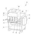
以下、本発明の好ましい実施形態について、図面を参照しながら説明する。図1は、本発明の一実施形態に係るクリーンベンチ20を搭載したファイバレーザ発振器10を示す概略図である。
Hereinafter, preferred embodiments of the present invention will be described with reference to the drawings. FIG. 1 is a schematic diagram showing a
図1に示すように、本実施形態のファイバレーザ発振器10は、筐体11と、複数の光学ユニット12と、ベースプレート13と、空調器14と、クリーンベンチ20と、を備える。
As shown in FIG. 1, the
筐体11は、その内側にレーザ光を生成するための光学ユニット12を複数収容する内部空間31が形成される。筐体11は、複数の光学ユニット12を上下方向に並んで収容可能に構成される。
The
光学ユニット12は、その内部に光ファイバが融着接続される融着接続部(図示省略)が設けられており、光学部品等が搭載される。複数の光学ユニット12についても種々のケーブルにより融着接続されている。なお、本実施形態の光学ユニット12は、レーザ光を生成するファイバレーザモジュールや複数のファイレーザが接続されるビームコンバイナ等の光ファイバがその内部で融着接続されるユニットである。また、本実施形態の光学ユニット12は、その天板を取り外すことによって内部が露出する構造となっている。
The
ベースプレート13は、光学ユニット12を支持する支持部材である。本実施形態のベースプレート13は、光学ユニット12を筐体11の内部に位置させる収容位置と、ベースプレート13によって支持される光学ユニット12を筐体11の外側に位置させる引出位置と、の間を水平方向に移動可能に構成される。ベースプレート13をスライド移動させる構成としては、例えばスライドレール等が用いられる。本実施形態では、ベースプレート13は、筐体11に収容する光学ユニット12の数に応じて設けられる。
The
空調器14は、筐体11及びクリーンベンチ20の内部の空調を行う。
The
クリーンベンチ20は、筐体11から引き出したベースプレート13に搭載される作業カバーであり、ファイバレーザ発振器10に対して着脱自在に構成される。クリーンベンチ20は、全体として持ち運び可能な小型に構成される。
The
次に、クリーンベンチ20の各構成について説明する。なお、以下の説明においてクリーンベンチ20における筐体11と対向する面を背面、背面の反対側を前面として説明する。
Next, each configuration of the
本実施形態のクリーンベンチ20は、前面及び下面が開放された箱型のベンチ本体21と、ベンチ本体21の開放された前面に取り付けられる前面パネル(図1の第1パネル50又は図2の第2パネル60)と、によって光学ユニット12の上方に閉鎖空間を形成する。
The
ベンチ本体21は、その全体形状が筐体11から引き出されたベースプレート13の内側に納まるサイズに形成されており、ベースプレート13に取り付けられる。また、ベンチ本体21における筐体11の内側に対向する面には、筐体11の内部空間31に連通する連通口22が形成される。
The
まず、図1に示される第1パネル50について説明する。第1パネル50は、光ファイバの融着処理を行うときに用いられる作業用パネルである。
First, the
本実施形態の第1パネル50は、ベンチ本体21の前面に取り付けられた状態で上部に位置する可視光透過板部51と、その下部に位置するカーテン部52と、を備える。
The
可視光透過板部51は、が可視光透過性の板で構成される板状部材である。作業者は、可視光透過板部51を通じてクリーンベンチ20の内部を視認できるようになっている。
The visible light
カーテン部52は、第1パネル50下部であって可視光透過板部51の下方に配置される。カーテン部52は、可視光透過性のある材料であって可撓性のある材料で構成される。
The
本実施形態のカーテン部52には、縦方向に延びる細長の隙間が形成される。例えば、縦に細長い長方形状の部材を横方向に複数配置する又は1つの部材に対して縦方向に延びるスリットを複数形成する等により、カーテン部52に縦方向に延びる細長の隙間を形成する。この隙間によって、作業者がカーテン部52を押し分けて手を入れた状態でも、クリーンベンチ20の内部が外部に大きく露出しないようにすることができる。
In the
以上説明した第1パネル50及びベンチ本体21からなるクリーンベンチ20により、ベースプレート13に支持された光学ユニット12の上方に閉鎖された作業空間が形成され、この作業空間で光学ユニット12の保守作業等を行うことが可能になっている。また、クリーンベンチ20は、ベースプレート13を介して取り付けられているので、光学ユニット12のケーシングの天板を外す作業についても閉鎖空間の中で行うことができる。
A closed work space is formed above the
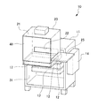
また、本実施形態のクリーンベンチ20は、ベンチ本体21の外部に配置される外部棚25を取り付け可能に構成される。図2は、外部棚25を取り付けた状態のクリーンベンチ20及びファイバレーザ発振器10を示す概略図である。
Further, the
図2では、ベンチ本体21から第1パネル50(又は後述する第2パネル60)が取り外された状態が示されている。第1パネル50が取り外された状態では、前面が開放されてクリーンベンチ20の内部空間40が露出する状態となっており、この開口部分を通じて光学ユニット12や光学ユニット12に内蔵される部品等の交換が可能になっている。
FIG. 2 shows a state in which the first panel 50 (or a
外部棚25は、クリーンベンチ20の外側面に配置される板状部材である。外部棚25は、光学ユニット12自体や光学ユニット12内部の光学部品を交換するときに、部品棚として使用される。この外部棚25は、その上面に部品交換に必要な治工具やベンコット等洗浄用の消耗品等を置くことができる。例えば、クリーンベンチ20のベンチ本体21から第1パネル50を取り外し、クリーンベンチ20の外側面に外部棚25取り付ける。この状態で破損品に接続される光ファイバを切断し、破損品の交換作業等を行ってクリーンベンチ20の内部で光ファイバを敷設する作業に移行する。
The
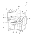
次に、光ファイバの融着処理について説明する。本実施形態の融着処理では、ベンチ本体21の内部に内部棚26をセットした状態で融着処理が行われる。図3は、内部棚26を取り付けた状態のクリーンベンチ20及びファイバレーザ発振器10を示す概略図である。なお、図3では、ベンチ本体21から第1パネル50(又は後述する第2パネル60)が取り外された状態が示されている。
Next, an optical fiber fusion process will be described. In the fusion process of the present embodiment, the fusion process is performed with the
図3に示すように、内部棚26は、ベンチ本体21内部の光学ユニット12の上方に配置される。本実施形態の内部棚26の内側面には、内部棚26を支持する枠部材としてのスライドレール(図示省略)が設けられる。融着処理を行うときは、前面が開放された状態のベンチ本体21に外側から内部棚26をスライドレールに沿わせて前面側から背面側に挿入し、ベンチ本体21の内側で固定する。枠部材に沿ってスライドさせる構造になっているので、挿入中に内部棚26が光学ユニット12側に落ちる事態も確実に防止される。
As shown in FIG. 3, the
固定された内部棚26の上に融着処理に用いる作業機器、例えば融着処理を行う融着機(図示省略)を載せる。内部棚26によって作業機器等が光学ユニット12側に誤って落ちることもなく、融着処理を安定した状態で行うことができる。光ファイバを融着機にセットした後に、可視光透過性に構成される第1パネル50をベンチ本体21に装着し、該クリーンベンチ20の内部のクリーン度が高くなった後に融着処理を行う。
On the fixed
作業者は、可視光透過板部51を通してクリーンベンチ20の内部の様子を確認しながら融着機を用いた作業を行うことができる。また、可視光透過板部51の下方には、カーテン部52が配置されているので、高いクリーン度を維持したまま融着機を操作することができる。融着処理後は、ベンチ本体21から第1パネル50を取り外し、光ファイバから取り外した融着機と内部棚26をクリーンベンチ20から取り出して、光ファイバの敷設作業に移行する。
An operator can perform an operation using a fusion machine while confirming the inside of the
次に、光ファイバの動作確認に用いる第2パネル60について説明する。図4は、第2パネル60を取り付けた状態のクリーンベンチ20及びファイバレーザ発振器10を示す概略図である。
Next, the
本実施形態の第2パネル60は、板状のベース部材61と、クリーンベンチ20の内部の湿度及び温度を検出する湿度・温度センサ90と、を備える。
The
板状のベース部材61は、ベンチ本体21の前面をカバーするように形成される。ベース部材61の平面部分の上中央には開口部62が形成される。湿度・温度センサ90は、ベース部材61の裏側に配置される。湿度・温度センサ90は、クリーンベンチ20内部の湿度及び温度を検出する機能を有する。
The plate-
以上説明した第2パネル60がベンチ本体21の前面に取り付けられる。上述の通り、クリーンベンチ20の内部は、そのベンチ本体21に形成される連通口22を通じて筐体11の内部に連通しており、クリーンベンチ20と筐体11の内部が湿度的に結合する構造となっている。
The
次に、第2パネル60をベンチ本体21に取り付けた状態で用いられる筐体11のカバー部材32について説明する。図4の斜線の領域に示すカバー部材32は、筐体11におけるクリーンベンチ20に隠れる部分以外の部分を覆うように取り付けられる。カバー部材32は、ビニルシート等の可撓性のある材料によって構成され、筐体11の内部空間31に粉塵が混入する事態を防止する。これによっても、現場において光学ユニット12内部への粉塵の混入を最小限に抑えることができる。
Next, the
また、カバー部材32によって筐体11の内部空間31が外部から閉鎖されるとともに、該内部空間31に連通口22を介してクリーンベンチ20の内部が連通しているので、クリーンベンチ20の内部と筐体11の内部空間の湿度及び温度がより同じ状態に近づく。従って、ファイバレーザ発振器10付属の空調器14によって筐体11の内部空間31に連通するクリーンベンチ20内部の湿度をより精密に管理することができる。
In addition, the
光ファイバの動作確認では、クリーンベンチ20が搭載されたファイバレーザ発振器10に第2パネル60及びカバー部材32が取り付けられた状態で、開口部62を通じてサーモグラフィ(図示省略)による光ファイバの温度測定が行われ、施設された光ファイバの異常の有無が確認される。従って、光学ユニット12の天板を開けたまま、内部の部品の動作確認をフィールドの現場で行うことが可能となる。
In confirming the operation of the optical fiber, the temperature of the optical fiber is measured by thermography (not shown) through the
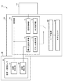
図5は、クリーンベンチ20を搭載するファイバレーザ発振器10の電気的構成の一部を模式的に示すブロック図である。本実施形態では、湿度・温度センサ90の検出値に基づいて結露を原因とする故障を防止するための制御が行われる。
FIG. 5 is a block diagram schematically showing a part of the electrical configuration of the
制御部70は、ファイバレーザ発振器10の各種の制御を行うコンピュータである。本実施形態の制御部70は、クリーンベンチ20内部の湿度をモニタし、クリーンベンチ20内部の湿度制御を行う。
The
図5に示すように、本実施形態の制御部70は、湿度制御部71と、出力指令部72と、露点温度計算部73と、アラーム検出部74と、を備える。
As shown in FIG. 5, the
湿度・温度センサ90の湿度検出部91によって検出されたクリーンベンチ20内部の湿度情報は、湿度制御部71と露点温度計算部73に送信される。また、湿度・温度センサ90の温度検出部92によって検出されたクリーンベンチ20内部の温度情報は、露点温度計算部73に送信される。
The humidity information inside the
湿度制御部71は、クリーンベンチ20内部の湿度情報に基づいて空調器14を制御してクリーンベンチ20内部の湿度を調節する。本実施形態では、予め設定された許容値を上回らないように空調器14を利用して湿度が制御される。これによって、光学ユニット12内部で生じる結露による部品故障を防止することができる。
The
出力指令部72は、レーザ電源80に接続されており、光学ユニット12の稼動及び停止を制御する。
The
露点温度計算部73は、クリーンベンチ20内部の湿度情報及び温度情報に基づいて露点温度を算出する。露点温度計算部73が算出した露点温度情報は、アラーム検出部74に送信される。
The dew point
アラーム検出部74は、露点温度計算部73によって算出された露点温度に基づいて結露が生じる状態か否かを判定し、クリーンベンチ20内部の結露が発生する温度に近づいている場合にはレーザ出力指令を停止する。これによって、光学ユニット12内部での結露が発生するような環境でファイバレーザ発振器10が稼動し、部品故障が生じる事態についても確実に防止できる。
The
以上説明した実施形態のクリーンベンチ20及びこれを搭載するファイバレーザ発振器10によれば、以下のような効果を奏する。
本実施形態のファイバレーザ発振器10は、光学ユニット12を引き出し可能に収容する筐体11と、光学ユニット12側に着脱自在であって、筐体11から引き出された光学ユニット12の上方に外部から隔絶された閉鎖空間を形成するクリーンベンチ20と、を備え、クリーンベンチ20には、筐体11の内部空間31に連通する連通口22が形成される。
According to the
The
これにより、着脱自在なクリーンベンチ20を光学ユニット12の上に搭載可能とすることにより、粉塵や湿気の多いフィールド環境下でも、光学ユニット12内部への粉塵の混入が防止しつつ、光学ユニット12及び光学ユニット12に搭載される光学部品の交換を効率的に行うことができる環境を容易に整えることができる。融着処理だけでなく、光ファイバの取り外しや敷設作業、光学ユニット12及び光学部品の交換作業、融着後の確認作業まで、効率の良い保守作業に利用することができ、ファイバレーザ発振器10の作業性を効果的に向上させることができる。また、連通口22によってファイバレーザ発振器10の筐体11内部とクリーンベンチ20内部の湿度環境が均一化し易くなり、湿度管理が行い易くなるので、結露の発生による光学部品の故障を効果的に防止でき、信頼性も向上する。例えば、光学ユニット12を引き出した状態で光学ユニット12内部の除湿を行うことが可能となる。従って、湿気の多い環境下でも、結露の発生による部品破損を防止しながら発振器を立ち上げて、光学部品の確認を行う作業が可能となる。また、クリーンベンチ20を着脱自在な構成にすることにより、フィールドの現場へ持ち運びが可能で軽量なクリーンベンチとなるので、通常、工場等のクリーンルームで行われる光ファイバの敷設や光学部品の装機、光ファイバの融着処理をフィールドの現場で行うことが可能となり、光学ユニット12や光学ユニット12に搭載される光学部品の保守交換作業を良好に行うことができる。
Thereby, the removable
また、本実施形態のファイバレーザ発振器10は、クリーンベンチ20内部の湿度を検出する湿度検出部91と、湿度検出部91の検出値に基づいてファイバレーザ発振器10が稼動可能か否かを判別する制御部70と、を備える。
The
これにより、クリーンベンチ20内部の湿度を管理して結露が生じている状態でファイバレーザ発振器10が稼動して光学部品等が故障する事態を確実に防止することができる。
As a result, it is possible to reliably prevent the
また、本実施形態のファイバレーザ発振器10は、光学ユニット12を固定し、筐体11から引き出し可能なベースプレート13を備え、クリーンベンチ20は、ベースプレート13に設置される。
Further, the
これにより、クリーンベンチ20が直接、光学ユニット12に搭載されている状態ではないので、クリーンベンチ20を配置した後に光学ユニット(ファイバレーザモジュールやビームコンバイナ等)12の天板を取り外すことができ、内部への粉塵の混入を確実に防止できる。
Accordingly, since the
また、本実施形態のクリーンベンチ20は、可視光透過板部51を有する。これにより、クリーンベンチ20によってクリーンな環境を維持しなから可視光透過板部51を通じてクリーンベンチ20の内部を確認しながら各種作業を行うことができる。
In addition, the
また、本実施形態のクリーンベンチ20は、筐体11に接する部分とは異なる外側面に可視透光性の材料であって可撓性を有する材料で構成されるカーテン部52を有する。
Moreover, the
これにより、クリーンベンチ20によってクリーンな環境を維持しなから可視透光性のあるカーテン部52からクリーンベンチ20内部に手や作業機を差し入れて内部の様子を確認しながら融着機等を用いた融着処理や保守作業を行うことができる。
As a result, a clean environment is not maintained by the
また、本実施形態のクリーンベンチ20は、その内部に内部棚26を配置可能に構成されるとともに外部に外部棚25を配置可能に構成される。これにより、フィールド現場において、内部棚26の上に融着機を置いたり、外部棚25の上に保守用の治工具を載せたりすることが可能となり、部品交換時の作業性をより一層向上させることができる。
In addition, the
以上、本発明の好ましい実施形態について説明したが、本発明は、上述の実施形態に制限されるものではなく、適宜変更が可能である。例えば、上記実施形態では、湿度制御部71は、クリーンベンチ20内部の湿度情報に基づいて湿度管理を行う構成であるが、露点温度計算部73によって算出された露点温度情報を考慮して湿度管理を行う構成としてもよい。
As mentioned above, although preferable embodiment of this invention was described, this invention is not restrict | limited to the above-mentioned embodiment, It can change suitably. For example, in the above embodiment, the
10 ファイバレーザ発振器
11 筐体
12 光学ユニット
20 クリーンベンチ
22 連通口
25 外部棚
26 内部棚
51 可視光透過板部(可視透光部)
52 カーテン部
70 制御部
91 湿度検出部
DESCRIPTION OF
52
Claims (7)
前記光学ユニットを引き出し可能に収容する筐体と、
前記筐体又は前記光学ユニット側に着脱自在であって、前記筐体から引き出された前記光学ユニットの上方に外部から隔絶された閉鎖空間を形成するクリーンベンチと、
を備え、
前記クリーンベンチには、前記筐体の内部空間に連通する連通口が形成されるファイバレーザ発振器。 A fiber laser oscillator comprising an optical unit having a fusion spliced portion to which an optical fiber is connected,
A housing for retractably housing the optical unit;
A clean bench that is detachable from the housing or the optical unit side and forms a closed space isolated from the outside above the optical unit drawn out from the housing;
With
A fiber laser oscillator in which a communication port communicating with the internal space of the housing is formed in the clean bench.
前記湿度検出部の検出値に基づいてファイバレーザ発振器が稼動可能か否かを判別する制御部と、を備える請求項1に記載のファイバレーザ発振器。 A humidity detector for detecting the humidity inside the clean bench;
The fiber laser oscillator of Claim 1 provided with the control part which discriminate | determines whether a fiber laser oscillator can operate | move based on the detected value of the said humidity detection part.
前記クリーンベンチは、前記ベースプレートに設置される請求項1又は2に記載のファイバレーザ発振器。 The optical unit is fixed and a base plate that can be pulled out from the housing is provided,
The fiber laser oscillator according to claim 1, wherein the clean bench is installed on the base plate.
前記筐体から引き出された前記光学ユニットの上方に外部から隔絶された閉鎖空間を形成するとともに、前記筐体の内部空間に連通する連通口が形成されるクリーンベンチ。 An optical unit having a fusion splicing portion to which an optical fiber is connected, and a fiber laser oscillator including a housing for retractably housing the optical unit, are detachable from the fiber laser oscillator,
A clean bench in which a closed space isolated from the outside is formed above the optical unit drawn out from the housing, and a communication port communicating with the internal space of the housing is formed.
Priority Applications (4)
| Application Number | Priority Date | Filing Date | Title |
|---|---|---|---|
| JP2016082100A JP6434443B2 (en) | 2016-04-15 | 2016-04-15 | Fiber laser oscillator |
| DE102017206075.1A DE102017206075B4 (en) | 2016-04-15 | 2017-04-10 | FIBER LASER OSCILLATOR |
| US15/484,362 US10027082B2 (en) | 2016-04-15 | 2017-04-11 | Fiber laser oscillator and clean bench mountable to the same |
| CN201710240712.4A CN107302173B (en) | 2016-04-15 | 2017-04-13 | Fibre laser oscillator |
Applications Claiming Priority (1)
| Application Number | Priority Date | Filing Date | Title |
|---|---|---|---|
| JP2016082100A JP6434443B2 (en) | 2016-04-15 | 2016-04-15 | Fiber laser oscillator |
Publications (2)
| Publication Number | Publication Date |
|---|---|
| JP2017191907A true JP2017191907A (en) | 2017-10-19 |
| JP6434443B2 JP6434443B2 (en) | 2018-12-05 |
Family
ID=59980802
Family Applications (1)
| Application Number | Title | Priority Date | Filing Date |
|---|---|---|---|
| JP2016082100A Active JP6434443B2 (en) | 2016-04-15 | 2016-04-15 | Fiber laser oscillator |
Country Status (4)
| Country | Link |
|---|---|
| US (1) | US10027082B2 (en) |
| JP (1) | JP6434443B2 (en) |
| CN (1) | CN107302173B (en) |
| DE (1) | DE102017206075B4 (en) |
Cited By (5)
| Publication number | Priority date | Publication date | Assignee | Title |
|---|---|---|---|---|
| WO2020004288A1 (en) * | 2018-06-29 | 2020-01-02 | パナソニックIpマネジメント株式会社 | Laser device and dehumidification management method for laser device |
| JP2020177990A (en) * | 2019-04-16 | 2020-10-29 | パナソニックIpマネジメント株式会社 | Laser equipment and laser processing equipment using it |
| JP2020177991A (en) * | 2019-04-16 | 2020-10-29 | パナソニックIpマネジメント株式会社 | Laser equipment and laser processing equipment using it |
| JP2021044279A (en) * | 2019-09-06 | 2021-03-18 | 株式会社アマダ | Fiber laser oscillator and maintenance system thereof |
| US11502476B2 (en) | 2019-12-06 | 2022-11-15 | Fanuc Corporation | Laser oscillator with enhanced maintainability |
Families Citing this family (3)
| Publication number | Priority date | Publication date | Assignee | Title |
|---|---|---|---|---|
| US11114809B2 (en) * | 2018-02-22 | 2021-09-07 | Lumentum Operations Llc | Fiber optic device operational monitoring |
| USD912339S1 (en) * | 2018-03-22 | 2021-03-02 | P-Laser N.V. | Laser cleaning device |
| DE112021003105T5 (en) * | 2020-06-03 | 2023-04-06 | Fanuc Corporation | laser device |
Citations (12)
| Publication number | Priority date | Publication date | Assignee | Title |
|---|---|---|---|---|
| JP2001343140A (en) * | 2000-06-01 | 2001-12-14 | Sankyo Seiki Mfg Co Ltd | Clean work module and clean tunnel |
| JP2002057385A (en) * | 2000-08-14 | 2002-02-22 | Komatsu Ltd | Laser device |
| JP2003060268A (en) * | 2001-08-21 | 2003-02-28 | Mitsubishi Electric Corp | Solid state laser device |
| JP2003083579A (en) * | 2001-09-11 | 2003-03-19 | Seiko Epson Corp | Clean space unit and clean air blowing unit |
| JP2004219878A (en) * | 2003-01-17 | 2004-08-05 | Orc Mfg Co Ltd | Wavelength conversion laser device |
| JP2005033040A (en) * | 2003-07-07 | 2005-02-03 | Cyber Laser Kk | Laser humidity controller |
| JP2005338618A (en) * | 2004-05-28 | 2005-12-08 | Nippon Tsushin Denzai Kk | Module mounted rack panel |
| JP2010054689A (en) * | 2008-08-27 | 2010-03-11 | Sumitomo Electric Ind Ltd | Working table for splicing optical fibers |
| WO2014065360A1 (en) * | 2012-10-26 | 2014-05-01 | コマツ産機株式会社 | Fiber laser processing machine, fiber connection method, and fiber laser oscillator |
| WO2014133013A1 (en) * | 2013-02-27 | 2014-09-04 | コマツ産機株式会社 | Method for controlling output of fiber laser processing machine, and fiber laser processing machine |
| JP2016015435A (en) * | 2014-07-03 | 2016-01-28 | 株式会社アマダホールディングス | Fiber laser oscillator, fiber laser processing apparatus, and fiber laser oscillator dehumidification method |
| US20160072248A1 (en) * | 2014-09-10 | 2016-03-10 | Bae Systems Information And Electronic Systems Integration Inc. | Ruggedized Fiber Optic Laser for High Stress Environments |
Family Cites Families (4)
| Publication number | Priority date | Publication date | Assignee | Title |
|---|---|---|---|---|
| US4578792A (en) * | 1982-09-30 | 1986-03-25 | Metalworking Lasers International Ltd. | High-power lasers |
| CH695872A5 (en) * | 2002-07-29 | 2006-09-29 | Brooks Pri Automation Switzerl | Reticle handling device. |
| US20130087292A1 (en) * | 2011-10-05 | 2013-04-11 | Don Gould | Welding Curtian |
| CN204615141U (en) * | 2015-05-15 | 2015-09-02 | 中国电子科技集团公司第四十六研究所 | A Modular Fiber Laser |
-
2016
- 2016-04-15 JP JP2016082100A patent/JP6434443B2/en active Active
-
2017
- 2017-04-10 DE DE102017206075.1A patent/DE102017206075B4/en active Active
- 2017-04-11 US US15/484,362 patent/US10027082B2/en active Active
- 2017-04-13 CN CN201710240712.4A patent/CN107302173B/en active Active
Patent Citations (12)
| Publication number | Priority date | Publication date | Assignee | Title |
|---|---|---|---|---|
| JP2001343140A (en) * | 2000-06-01 | 2001-12-14 | Sankyo Seiki Mfg Co Ltd | Clean work module and clean tunnel |
| JP2002057385A (en) * | 2000-08-14 | 2002-02-22 | Komatsu Ltd | Laser device |
| JP2003060268A (en) * | 2001-08-21 | 2003-02-28 | Mitsubishi Electric Corp | Solid state laser device |
| JP2003083579A (en) * | 2001-09-11 | 2003-03-19 | Seiko Epson Corp | Clean space unit and clean air blowing unit |
| JP2004219878A (en) * | 2003-01-17 | 2004-08-05 | Orc Mfg Co Ltd | Wavelength conversion laser device |
| JP2005033040A (en) * | 2003-07-07 | 2005-02-03 | Cyber Laser Kk | Laser humidity controller |
| JP2005338618A (en) * | 2004-05-28 | 2005-12-08 | Nippon Tsushin Denzai Kk | Module mounted rack panel |
| JP2010054689A (en) * | 2008-08-27 | 2010-03-11 | Sumitomo Electric Ind Ltd | Working table for splicing optical fibers |
| WO2014065360A1 (en) * | 2012-10-26 | 2014-05-01 | コマツ産機株式会社 | Fiber laser processing machine, fiber connection method, and fiber laser oscillator |
| WO2014133013A1 (en) * | 2013-02-27 | 2014-09-04 | コマツ産機株式会社 | Method for controlling output of fiber laser processing machine, and fiber laser processing machine |
| JP2016015435A (en) * | 2014-07-03 | 2016-01-28 | 株式会社アマダホールディングス | Fiber laser oscillator, fiber laser processing apparatus, and fiber laser oscillator dehumidification method |
| US20160072248A1 (en) * | 2014-09-10 | 2016-03-10 | Bae Systems Information And Electronic Systems Integration Inc. | Ruggedized Fiber Optic Laser for High Stress Environments |
Cited By (11)
| Publication number | Priority date | Publication date | Assignee | Title |
|---|---|---|---|---|
| WO2020004288A1 (en) * | 2018-06-29 | 2020-01-02 | パナソニックIpマネジメント株式会社 | Laser device and dehumidification management method for laser device |
| JPWO2020004288A1 (en) * | 2018-06-29 | 2021-08-12 | パナソニックIpマネジメント株式会社 | Laser device and dehumidification management method for laser device |
| JP7266183B2 (en) | 2018-06-29 | 2023-04-28 | パナソニックIpマネジメント株式会社 | Laser device and dehumidification control method for laser device |
| US11896929B2 (en) | 2018-06-29 | 2024-02-13 | Panasonic Intellectual Property Management Co., Ltd. | Laser device and dehumidification management method for laser device |
| JP2020177990A (en) * | 2019-04-16 | 2020-10-29 | パナソニックIpマネジメント株式会社 | Laser equipment and laser processing equipment using it |
| JP2020177991A (en) * | 2019-04-16 | 2020-10-29 | パナソニックIpマネジメント株式会社 | Laser equipment and laser processing equipment using it |
| JP7228809B2 (en) | 2019-04-16 | 2023-02-27 | パナソニックIpマネジメント株式会社 | LASER DEVICE AND LASER PROCESSING DEVICE USING THE SAME |
| JP7228810B2 (en) | 2019-04-16 | 2023-02-27 | パナソニックIpマネジメント株式会社 | LASER DEVICE AND LASER PROCESSING DEVICE USING THE SAME |
| JP2021044279A (en) * | 2019-09-06 | 2021-03-18 | 株式会社アマダ | Fiber laser oscillator and maintenance system thereof |
| JP7257295B2 (en) | 2019-09-06 | 2023-04-13 | 株式会社アマダ | Fiber laser oscillator and maintenance system for fiber laser oscillator |
| US11502476B2 (en) | 2019-12-06 | 2022-11-15 | Fanuc Corporation | Laser oscillator with enhanced maintainability |
Also Published As
| Publication number | Publication date |
|---|---|
| CN107302173B (en) | 2019-11-01 |
| CN107302173A (en) | 2017-10-27 |
| US20170302046A1 (en) | 2017-10-19 |
| DE102017206075A1 (en) | 2017-10-19 |
| US10027082B2 (en) | 2018-07-17 |
| DE102017206075B4 (en) | 2019-12-24 |
| JP6434443B2 (en) | 2018-12-05 |
Similar Documents
| Publication | Publication Date | Title |
|---|---|---|
| JP6434443B2 (en) | Fiber laser oscillator | |
| WO2014080500A1 (en) | Component mounting machine | |
| JP6251684B2 (en) | Fiber laser processing machine, fiber connecting method, and fiber laser oscillator | |
| CN103728325A (en) | X-ray analysis apparatus | |
| CN101970982B (en) | Shape measuring device and robot device with the same | |
| US11077520B1 (en) | Laser processing head and laser processing system including the same | |
| JP6816672B2 (en) | Input / output device production method and input / output device | |
| KR101215828B1 (en) | Flatness gauge for steel plate | |
| WO2018135090A1 (en) | Projector device | |
| JP2006184283A (en) | System for inspecting disc-shaped objects | |
| JP4412090B2 (en) | Light irradiator | |
| CN203443542U (en) | Measuring machine | |
| US10821552B2 (en) | Modular laser processing enclosure and system | |
| JP2005529426A (en) | Controller, control unit for industrial process control system, and industrial process control system with such control unit | |
| JP2017216355A (en) | Motor drive device having fan maintenance structure with good workability | |
| US20230150059A1 (en) | Laser processing apparatus | |
| JP6248446B2 (en) | control panel | |
| KR100774559B1 (en) | Printed Circuit Board Cutting Equipment | |
| EP4424455A1 (en) | Optical system | |
| JP2009093661A6 (en) | Operating device for the operation of machine tools, production machines and / or robots | |
| JP2009093661A (en) | Operating device for the operation of machine tools, production machines and / or robots | |
| JP4981404B2 (en) | Particle counter type smoke detector | |
| JP2020062725A (en) | Processing device | |
| KR100511491B1 (en) | Jig of sensor for counting apparatus of wafer | |
| JP2009031275A (en) | Rack for measuring instrument |
Legal Events
| Date | Code | Title | Description |
|---|---|---|---|
| A977 | Report on retrieval |
Free format text: JAPANESE INTERMEDIATE CODE: A971007 Effective date: 20180517 |
|
| A131 | Notification of reasons for refusal |
Free format text: JAPANESE INTERMEDIATE CODE: A131 Effective date: 20180529 |
|
| A521 | Request for written amendment filed |
Free format text: JAPANESE INTERMEDIATE CODE: A523 Effective date: 20180626 |
|
| A131 | Notification of reasons for refusal |
Free format text: JAPANESE INTERMEDIATE CODE: A131 Effective date: 20180807 |
|
| A521 | Request for written amendment filed |
Free format text: JAPANESE INTERMEDIATE CODE: A523 Effective date: 20180904 |
|
| A521 | Request for written amendment filed |
Free format text: JAPANESE INTERMEDIATE CODE: A523 Effective date: 20180913 |
|
| TRDD | Decision of grant or rejection written | ||
| A01 | Written decision to grant a patent or to grant a registration (utility model) |
Free format text: JAPANESE INTERMEDIATE CODE: A01 Effective date: 20181016 |
|
| A61 | First payment of annual fees (during grant procedure) |
Free format text: JAPANESE INTERMEDIATE CODE: A61 Effective date: 20181108 |
|
| R150 | Certificate of patent or registration of utility model |
Ref document number: 6434443 Country of ref document: JP Free format text: JAPANESE INTERMEDIATE CODE: R150 |