JP2017191976A - Control method of communication system and communication system - Google Patents
Control method of communication system and communication system Download PDFInfo
- Publication number
- JP2017191976A JP2017191976A JP2016079250A JP2016079250A JP2017191976A JP 2017191976 A JP2017191976 A JP 2017191976A JP 2016079250 A JP2016079250 A JP 2016079250A JP 2016079250 A JP2016079250 A JP 2016079250A JP 2017191976 A JP2017191976 A JP 2017191976A
- Authority
- JP
- Japan
- Prior art keywords
- video
- network
- delay time
- control terminal
- network switch
- Prior art date
- Legal status (The legal status is an assumption and is not a legal conclusion. Google has not performed a legal analysis and makes no representation as to the accuracy of the status listed.)
- Granted
Links
Images


Landscapes
- Two-Way Televisions, Distribution Of Moving Picture Or The Like (AREA)
- Data Exchanges In Wide-Area Networks (AREA)
Abstract
【課題】IPネットワークを介して映像信号を送る際に、帯域資源を節約でき、映像不具合も低減できる通信システムの制御方法及び通信システムを提供することを目的とする。【解決手段】本開示の通信システムの制御方法は、遠隔地から伝送されてきた映像をネットワーク内で選択可能にすることによって無駄な映像伝送を回避してネットワーク帯域を節約できる。また、ネットワークの遅延時間に基づいて送信装置からの映像パケットの送信及びネットワークスイッチの切替を時間先行して行うことで切り替え時の映像不具合を低減することができる。【選択図】図4An object of the present invention is to provide a communication system control method and a communication system that can save bandwidth resources and reduce video defects when transmitting a video signal via an IP network. According to a control method of a communication system of the present disclosure, it is possible to select a video transmitted from a remote place within a network, thereby avoiding unnecessary video transmission and saving a network bandwidth. In addition, it is possible to reduce video defects at the time of switching by transmitting video packets from the transmitting device and switching the network switch in advance based on the delay time of the network. [Selection] Figure 4
Description
本開示は、遠隔地からの映像を、ネットワークを使って効率的に送る技術に関する。 The present disclosure relates to a technique for efficiently transmitting video from a remote location using a network.
これまでは映像信号をネットワークで送る場合は、SDI(Serial Digital Interface)規格に準拠した信号を、同軸ケーブル(SDIケーブル)を通じて送っていた。さらに、その信号を任意の場所に送るためにSDIルーティングスイッチを導入し、そのスイッチを制御し、信号を転送していた。 In the past, when a video signal was sent over a network, a signal conforming to the SDI (Serial Digital Interface) standard was sent through a coaxial cable (SDI cable). Furthermore, in order to send the signal to an arbitrary place, an SDI routing switch was introduced, the switch was controlled, and the signal was transferred.
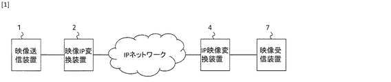
しかしながらSDI規格は放送局などの単一の建物の中を配線するために策定された規格であることから100mを超える距離の伝送には対応していない。そのため、例えば、外部のスタジアム等から長距離伝送する場合はIP(Internet Protocol)パケットに変換する装置(例えば、非特許文献1および2を参照。)を使って、図1のようにIPネットワークを介して送る方法が一般的である。
However, since the SDI standard is a standard established for wiring in a single building such as a broadcasting station, it does not support transmission over a distance exceeding 100 m. Therefore, for example, in the case of long-distance transmission from an external stadium or the like, an IP network is converted as shown in FIG. 1 using a device (for example, see Non-Patent
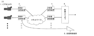
IPネットワークを介して映像信号を送る、例えば、前例のように外部のスタジアムから放送局まで映像信号を送る場合、外部のスタジアムから、放送に使う・使わないに関わらず撮影された映像を放送局まで送り放送局で受信して、放送局で映像スイッチャを使って選択している(図2)。ハイビジョン映像1本は1.485Gbpsのネットワーク帯域を必要とするため、使わない映像を送ることは大きなネットワーク帯域を無駄に消費するだけでなく、従量制課金のネットワークを利用している場合は映像伝送コストに大きな影響を与えることになる。 For example, when sending video signals from an external stadium to a broadcasting station as in the previous example, video images taken from an external stadium, regardless of whether they are used for broadcasting or not, are broadcast to the broadcasting station. The broadcast station receives the data and receives it at the broadcast station, and the broadcast station selects it using a video switcher (FIG. 2). Since one high-definition video requires a network bandwidth of 1.485 Gbps, sending unused video not only wastes a large network bandwidth, but also video transmission when using a pay-per-use network. The cost will be greatly affected.
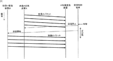
無駄な映像を送らないようにするために、受信側から必要としない映像を送信しないように該当する送信側装置の送信を止めることも考えられる。そのような使い方で映像を切り替えようとした場合、送信中の装置を一旦止めて新しい映像の送信を開始させることができるが、ネットワークの遅延時間があるため、切り替えの間、映像が中断する可能性がある(図3)。 In order not to send useless video, it is also conceivable to stop transmission of the corresponding transmitting device so as not to transmit unnecessary video from the receiving side. If you try to switch the video in such a way, you can stop the transmitting device and start transmitting a new video, but there is a network delay time, so the video can be interrupted during the switching (Figure 3).
また、映像の中断が生じないように、既に映像送信をしている装置を止めずに、切り替え先の送信装置から映像送信を開始すると、2つの送信装置からの映像信号が同時に1つの受信装置に到着することになり、映像が乱れる可能性がある。 In addition, when video transmission is started from the switching destination transmission device without stopping the device that has already transmitted video so that the video is not interrupted, video signals from the two transmission devices are simultaneously received by one reception device. The video may be distorted.
このように、IPネットワークを介して映像信号を送る手法には、帯域資源を節約しようとすると映像不具合が発生するというトレードオフの関係があった。そこで、本開示の発明は、IPネットワークを介して映像信号を送る際に、帯域資源を節約でき、映像不具合も低減できる通信システムの制御方法及び通信システムを提供することを目的とする。 As described above, the technique of sending a video signal via an IP network has a trade-off relationship that a video defect occurs when attempting to save bandwidth resources. Therefore, an object of the present disclosure is to provide a communication system control method and a communication system that can save bandwidth resources and reduce video defects when transmitting a video signal via an IP network.
上記目的を達成するために、本開示の通信システムの制御方法は、ネットワークの遅延時間に基づいて送信装置からの映像パケットの送信及びネットワークスイッチの切替を時間先行して行うこととした。 In order to achieve the above object, according to the control method of the communication system of the present disclosure, transmission of a video packet from a transmission device and switching of a network switch are performed in advance in time based on a delay time of the network.
具体的には、本発明に係る通信システムの第1制御方法は、
映像信号をネットワークで送信可能な映像パケットに変換して前記ネットワークに送信する複数のパケット化装置と、
前記パケット化装置からの映像パケットを透過又は廃棄する1または複数のネットワークスイッチと、
前記ネットワークから映像パケットを受信して映像信号に復号する復号装置と、
前記ネットワーク経由で前記パケット化装置及び前記ネットワークスイッチの動作を制御する制御端末と、
を備える通信システムの制御方法であって、
前記制御端末と前記ネットワークスイッチとの間の遅延時間、前記パケット化装置と前記復号装置との間の遅延時間、前記制御端末と前記パケット化装置との間の遅延時間、及び前記ネットワークスイッチと前記復号装置との間の遅延時間を測定する遅延時間検出手順と、
1の前記パケット化装置からの映像パケットを前記ネットワークスイッチが透過させて前記復号装置が前記映像パケットを受信しているときに、前記遅延時間検出手順で測定した遅延時間に基づき他の前記パケット化装置からの映像パケットを前記復号装置が受信するであろう時刻が切替完了時刻より前となるように、前記制御端末が他の前記パケット化装置へ映像パケットを送信させる送信開始指示を行う送信開始手順と、
前記送信開始手順の後、他の前記パケット化装置からの映像パケットを前記ネットワークスイッチが廃棄しているときに、前記遅延時間検出手順で測定した遅延時間に基づき前記切替完了時刻に他の前記パケット化装置からの映像パケットを前記復号装置が受信するように、1の前記パケット化装置からの映像パケットを廃棄して他の前記パケット化装置からの映像パケットを透過する映像切替指示を前記制御端末が前記ネットワークスイッチへ行う映像切替指示手順と、
前記映像切替指示手順の後、1の前記パケット化装置へ映像パケットの送信を停止させる送信停止指示を行う送信停止指示手順と、
を行う。
Specifically, the first control method of the communication system according to the present invention is:
A plurality of packetizing devices for converting video signals into video packets that can be transmitted over a network and transmitting the video packets to the network;
One or more network switches for transmitting or discarding video packets from the packetizer;
A decoding device that receives video packets from the network and decodes them into video signals;
A control terminal for controlling the operation of the packetizer and the network switch via the network;
A communication system control method comprising:
A delay time between the control terminal and the network switch, a delay time between the packetizer and the decoder, a delay time between the control terminal and the packetizer, and the network switch and the A delay time detection procedure for measuring a delay time with the decoding device;
When the network switch transmits the video packet from one of the packetizing devices and the decoding device receives the video packet, the other packetization is performed based on the delay time measured in the delay time detection procedure. Transmission start in which the control terminal issues a transmission start instruction to transmit the video packet to the other packetizing device so that the time at which the decoding device will receive the video packet from the device is before the switching completion time Procedure and
After the transmission start procedure, when the network switch discards the video packet from the other packetizing device, the other packet at the switching completion time based on the delay time measured in the delay time detection procedure. In order for the decoding device to receive the video packet from the packetizing device, the control terminal issues a video switching instruction that discards the video packet from one packetizing device and transmits the video packet from the other packetizing device. A video switching instruction procedure performed by the network switch;
A transmission stop instruction procedure for performing a transmission stop instruction to stop transmission of a video packet to one of the packetizers after the video switching instruction procedure;
I do.
また、本発明に係る通信システムの第1制御方法において、
前記送信開始手順では、前記切替完了時刻、前記制御端末と前記パケット化装置との間の遅延時間及び前記パケット化装置と前記復号装置との間の遅延時間から計算した時刻より前に前記送信開始指示を行い、
前記映像切替指示手順では、前記切替完了時刻、前記制御端末と前記ネットワークスイッチとの間の遅延時間及び前記ネットワークスイッチと前記復号装置との間の遅延時間から計算した時刻に前記映像切替指示を行う
ことを特徴とする。
In the first control method of the communication system according to the present invention,
In the transmission start procedure, the transmission starts before the time calculated from the switching completion time, the delay time between the control terminal and the packetizer, and the delay time between the packetizer and the decoder. Give instructions,
In the video switching instruction procedure, the video switching instruction is performed at a time calculated from the switching completion time, a delay time between the control terminal and the network switch, and a delay time between the network switch and the decoding device. It is characterized by that.
第1制御方法を実現できる本発明に係る通信システムは、
映像信号をネットワークで送信可能な映像パケットに変換して前記ネットワークに送信する複数のパケット化装置と、
前記パケット化装置からの映像パケットを透過又は廃棄する1または複数のネットワークスイッチと、
前記ネットワークから映像パケットを受信して映像信号に復号する復号装置と、
前記ネットワーク経由で前記パケット化装置及び前記ネットワークスイッチの動作を制御する制御端末と、
を備える通信システムであって、
前記制御端末が上記通信システムの制御方法を行うことを特徴とする。
The communication system according to the present invention capable of realizing the first control method is:
A plurality of packetizing devices for converting video signals into video packets that can be transmitted over a network and transmitting the video packets to the network;
One or more network switches for transmitting or discarding video packets from the packetizer;
A decoding device that receives video packets from the network and decodes them into video signals;
A control terminal for controlling the operation of the packetizer and the network switch via the network;
A communication system comprising:
The control terminal performs a control method of the communication system.
一方、本発明に係る通信システムの第2制御方法は、
映像信号をネットワークで送信可能な映像パケットに変換して前記ネットワークに送信する複数のパケット化装置と、
前記パケット化装置からの映像パケットを透過又は廃棄する1または複数のネットワークスイッチと、
前記ネットワークから映像パケットを受信して映像信号に復号する復号装置と、
前記ネットワーク経由で前記ネットワークスイッチの動作を制御する制御端末と、
を備え、
前記復号装置からの定期的なフィードバックパケットを受信することで前記パケット化装置が映像パケットを送信する通信システムの制御方法であって、
前記制御端末と前記ネットワークスイッチとの間の遅延時間、前記パケット化装置と前記復号装置との間の遅延時間、及び前記ネットワークスイッチと前記復号装置との間の遅延時間を測定する遅延時間検出手順と、
1の前記パケット化装置からの映像パケットを前記ネットワークスイッチが透過させて前記復号装置が前記映像パケットを受信しているときに、前記遅延時間検出手順で測定した遅延時間に基づき他の前記パケット化装置からの映像パケットを前記復号装置が受信するであろう時刻が切替完了時刻より前となるように、前記制御端末が前記ネットワークスイッチへ前記フィードバックパケットの宛先を1の前記パケット化装置から他の前記パケット化装置へ書き換えるフィードバック切替指示を行うフィードバック切替指示手順と、
前記フィードバック切替指示手順の後、前記遅延時間検出手順で測定した遅延時間に基づき前記切替完了時刻に他の前記パケット化装置からの映像パケットを前記復号装置が受信するように、1の前記パケット化装置からの映像パケットを廃棄して他の前記パケット化装置からの映像パケットを透過する映像切替指示を前記制御端末が前記ネットワークスイッチへ行う映像切替指示手順と、
を行う。
On the other hand, the second control method of the communication system according to the present invention is:
A plurality of packetizing devices for converting video signals into video packets that can be transmitted over a network and transmitting the video packets to the network;
One or more network switches for transmitting or discarding video packets from the packetizer;
A decoding device that receives video packets from the network and decodes them into video signals;
A control terminal for controlling the operation of the network switch via the network;
With
A control method of a communication system in which the packetizing device transmits a video packet by receiving a periodic feedback packet from the decoding device,
Delay time detection procedure for measuring a delay time between the control terminal and the network switch, a delay time between the packetizer and the decoder, and a delay time between the network switch and the decoder When,
When the network switch transmits the video packet from one of the packetizing devices and the decoding device receives the video packet, the other packetization is performed based on the delay time measured in the delay time detection procedure. The control terminal sends the destination of the feedback packet from the one packetizer to the network switch so that the time at which the decoding device will receive the video packet from the device is before the switching completion time. A feedback switching instruction procedure for performing a feedback switching instruction to be rewritten to the packetizer;
After the feedback switching instruction procedure, one packetization is performed so that the decoding device receives a video packet from another packetization device at the switching completion time based on the delay time measured in the delay time detection procedure. A video switching instruction procedure in which the control terminal sends a video switching instruction to discard the video packet from the apparatus and transmits the video packet from the other packetizing apparatus to the network switch;
I do.
また、本発明に係る通信システムの第2制御方法において、
前記フィードバック切替指示手順では、前記切替完了時刻、前記復号装置と前記パケット化装置との間の遅延時間、前記ネットワークスイッチと前記復号装置との間の遅延時間及び前記制御端末と前記ネットワークスイッチとの間の遅延時間から計算した時刻より前に前記フィードバック切替指示を行い、
前記映像切替指示手順では、前記切替完了時刻、前記制御端末と前記ネットワークスイッチとの間の遅延時間及び前記ネットワークスイッチと前記復号装置との間の遅延時間から計算した時刻に前記映像切替指示を行う
ことを特徴とする。
In the second control method of the communication system according to the present invention,
In the feedback switching instruction procedure, the switching completion time, the delay time between the decoding device and the packetizing device, the delay time between the network switch and the decoding device, and between the control terminal and the network switch Instruct the feedback switching before the time calculated from the delay time between,
In the video switching instruction procedure, the video switching instruction is performed at a time calculated from the switching completion time, a delay time between the control terminal and the network switch, and a delay time between the network switch and the decoding device. It is characterized by that.
第2制御方法を実現できる本発明に係る通信システムは、
映像信号をネットワークで送信可能な映像パケットに変換して前記ネットワークに送信する複数のパケット化装置と、
前記パケット化装置からの映像パケットを透過又は廃棄する1または複数のネットワークスイッチと、
前記ネットワークから映像パケットを受信して映像信号に復号する復号装置と、
前記ネットワーク経由で前記ネットワークスイッチの動作を制御する制御端末と、
を備え、
前記復号装置からの定期的なフィードバックパケットを受信することで前記パケット化装置が映像パケットを送信する通信システムであって、
前記制御端末が上記通信システムの制御方法を行うことを特徴とする。
The communication system according to the present invention capable of realizing the second control method is:
A plurality of packetizing devices for converting video signals into video packets that can be transmitted over a network and transmitting the video packets to the network;
One or more network switches for transmitting or discarding video packets from the packetizer;
A decoding device that receives video packets from the network and decodes them into video signals;
A control terminal for controlling the operation of the network switch via the network;
With
A communication system in which the packetizer transmits video packets by receiving periodic feedback packets from the decoder,
The control terminal performs a control method of the communication system.
本開示の通信システムは、遠隔地から伝送されてきた映像をネットワーク内で選択可能にすることによって無駄な映像伝送を回避してネットワーク帯域を節約できる。また、ネットワークの遅延時間に基づいて送信装置からの映像パケットの送信及びネットワークスイッチの切替を時間先行して行うことで切り替え時の映像不具合を低減することができる。 The communication system of the present disclosure can save useless video transmission and save network bandwidth by making it possible to select video transmitted from a remote location within the network. In addition, it is possible to reduce video defects at the time of switching by transmitting video packets from the transmitting device and switching the network switch in advance based on the delay time of the network.
従って、本開示の発明は、IPネットワークを介して映像信号を送る際に、帯域資源を節約でき、映像不具合も低減できる通信システムの制御方法及び通信システムを提供することができる。 Accordingly, the invention of the present disclosure can provide a communication system control method and a communication system that can save bandwidth resources and reduce video defects when transmitting a video signal via an IP network.
本発明に係る通信システムの第1と第2制御方法は、
前記制御端末と前記低解像度映像生成エンコーダとの間の遅延時間を測定する第2の遅延時間検出手順と、
低解像度映像生成エンコーダで前記映像信号を低解像度化した低解像度映像を前記制御端末が受信する低解像度映像受信手順と、
1の前記パケット化装置と前記復号装置との間の遅延時間と1の前記ネットワークスイッチと前記復号装置との間の遅延時間とから1の前記パケット化装置と1の前記ネットワークスイッチとの間の1の計算遅延時間を計算し、前記1の計算遅延時間を、前記制御端末と1の前記ネットワークスイッチとの間の遅延時間と前記制御端末と1の前記低解像度映像生成エンコーダとの間の遅延時間との和から差し引いた時間と、他の前記パケット化装置と前記復号装置との間の遅延時間と他の前記ネットワークスイッチと前記復号装置との間の遅延時間とから他の前記パケット化装置と他の前記ネットワークスイッチとの間の他の計算遅延時間を計算し、前記他の計算遅延時間を、前記制御端末と他の前記ネットワークスイッチとの間の遅延時間と前記制御端末と他の前記低解像度映像生成エンコーダとの間の遅延時間との和から差し引いた時間のうち大きい方の遅延時間で1の前記パケット化装置及び他の前記パケット化装置に入力する映像信号を遅延させる映像信号遅延手順と、
をさらに行うことを特徴とする。
The first and second control methods of the communication system according to the present invention are:
A second delay time detection procedure for measuring a delay time between the control terminal and the low-resolution video generation encoder;
A low-resolution video reception procedure in which the control terminal receives a low-resolution video obtained by reducing the resolution of the video signal by a low-resolution video generation encoder;
Between one packetizer and one network switch from one delay between the packetizer and the decoder and one delay between the network switch and the
Is further performed.
映像配信の運用者は、端末装置の画面を見ながら切替指示を行うことで切り替えたいシーンで映像切替ができる。 The video distribution operator can switch the video in the scene to be switched by issuing a switching instruction while viewing the screen of the terminal device.
本開示の発明は、IPネットワークを介して映像信号を送る際に、帯域資源を節約でき、映像不具合も低減できる通信システムの制御方法及び通信システムを提供することができる。 The invention of the present disclosure can provide a control method and a communication system of a communication system that can save bandwidth resources and reduce video defects when transmitting a video signal via an IP network.
添付の図面を参照して本発明の実施形態を説明する。以下に説明する実施形態は本発明の実施例であり、本発明は、以下の実施形態に制限されるものではない。なお、本明細書及び図面において符号が同じ構成要素は、相互に同一のものを示すものとする。 Embodiments of the present invention will be described with reference to the accompanying drawings. The embodiments described below are examples of the present invention, and the present invention is not limited to the following embodiments. In the present specification and drawings, the same reference numerals denote the same components.
(実施形態1)
本実施形態の通信システムは、
映像信号をネットワークで送信可能な映像パケットに変換して前記ネットワークに送信する複数のパケット化装置と、
前記パケット化装置からの映像パケットを透過又は廃棄する1または複数のネットワークスイッチと、
前記ネットワークから映像パケットを受信して映像信号に復号する復号装置と、
前記ネットワーク経由で前記パケット化装置及び前記ネットワークスイッチの動作を制御する制御端末と、
を備える。
(Embodiment 1)
The communication system of this embodiment is
A plurality of packetizing devices for converting video signals into video packets that can be transmitted over a network and transmitting the video packets to the network;
One or more network switches for transmitting or discarding video packets from the packetizer;
A decoding device that receives video packets from the network and decodes them into video signals;
A control terminal for controlling the operation of the packetizer and the network switch via the network;
Is provided.
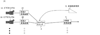
図4は、本実施形態のライブ中継用の長距離映像伝送システムを説明する構成例である。図中の1Aおよび1Bは中継先での撮影のためのビデオカメラ、2Aおよび2Bはビデオカメラ1Aおよび1Bからの映像信号をIPパケットに変換する映像IP変換装置(前記パケット化装置に相当する。)、3はOpenFlowコマンドによって遠隔制御可能なOpenFlowスイッチ(前記ネットワークスイッチに相当する。)、4はIPパケット化された映像を映像信号に復元するIP映像変換装置(前記復号装置に相当する。)、5はOpenFlowスイッチを遠隔制御するための受信制御端末(前記制御端末に相当する。)である。
FIG. 4 is a configuration example illustrating the long-distance video transmission system for live relay according to this embodiment. In the figure, 1A and 1B are video cameras for shooting at the relay destination, and 2A and 2B are video IP converters (corresponding to the packetizers) that convert video signals from the video cameras 1A and 1B into IP packets. ) 3 is an OpenFlow switch that can be remotely controlled by an OpenFlow command (corresponding to the network switch), and 4 is an IP video conversion device (corresponding to the decoding device) that restores IP packetized video to a video signal.
映像IP変換装置2Aと2Bはネットワーク経由で映像をIPパケット化して送信開始ができ、同じようにネットワーク経由で送信の終了ができる装置である。映像IP変換装置2A、2BとOpenFlowスイッチ3、およびOpenFlowスイッチ3とIP映像変換装置4はIPネットワークで接続され、ビデオカメラ1Aと映像IP変換装置2A、ビデオカメラ1Bと映像IP変換装置2BはSDI規格のインタフェースで接続されている。IP映像変換装置4の出力は放送局内のシステムへと接続される。
本実施形態では、ビデオカメラ1Aからの映像を映像IP変換装置2AでIPパケットに変換して、OpenFlowスイッチ3を介して、IP映像変換装置4で映像信号に復元して放送設備に送り、その後、ビデオカメラ1Bからの映像に切り替える例によって、本発明の詳細を説明する。この例では、判りやすくするため各装置の処理時間を無視できるくらい小さいと仮定する。
In this embodiment, the video from the video camera 1A is converted into an IP packet by the video
[遅延時間検出手順]
本長距離映像伝送システムは、前記制御端末と前記ネットワークスイッチとの間の遅延時間、前記パケット化装置と前記復号装置との間の遅延時間、前記制御端末と前記パケット化装置との間の遅延時間、及び前記ネットワークスイッチと前記復号装置との間の遅延時間を測定する遅延時間検出手順を行う。
[Delay time detection procedure]
The long distance video transmission system includes a delay time between the control terminal and the network switch, a delay time between the packetizer and the decoder, and a delay between the control terminal and the packetizer. A delay time detection procedure for measuring time and a delay time between the network switch and the decoding device is performed.
具体的には、本長距離映像伝送システムは、切り替えに先立ち、まず、受信制御端末5とOpenFlowスイッチ3との間の往復遅延時間(Round Trip Time、以降RTT)、IP映像変換装置4と映像IP変換装置2A、2Bとの間のRTT、受信制御端末5と映像IP変換装置2A、2Bとの間のRTT、及びIP映像変換装置4とOpenFlowスイッチ3との間のRTTを事前に評価する。RTTの評価には様々な方法がある。例えば、IPネットワークで通信可能な多くの機器にping内部コマンドとして実装されているICMP Echoパケット送信機能を使うことによって評価が可能である。本実施形態では、事前に評価したRTTを次のように記載する。
T53:受信制御端末5とOpenFlowスイッチ3との間のRTT
T42A:IP映像変換装置4と映像IP変換装置2Aとの間のRTT
T42B:IP映像変換装置4と映像IP変換装置2Bとの間のRTT
T52A:受信制御端末5と映像IP変換装置2Aとの間のRTT
T52B:受信制御端末5と映像IP変換装置2Bとの間のRTT
T43:IP映像変換装置4とOpenFlowスイッチ3との間のRTT
Specifically, prior to switching, the long-distance video transmission system firstly includes a round trip time (RTP) between the
T53: RTT between the
T42A: RTT between the IP
T42B: RTT between the IP
T52A: RTT between the
T52B: RTT between the
T43: RTT between the IP
図5は、本長距離映像伝送システムでの映像の切り替え手順を説明するシーケンス図である。この図は時刻T0において映像の切り替えを実行する例を示している。最初の状態はビデオカメラ1Aの映像を映像IP変換装置2AでIPパケットに変換し、OpenFlowスイッチ3を介して映像IP変換装置4へ送信している状態である。
FIG. 5 is a sequence diagram illustrating a video switching procedure in the long distance video transmission system. This figure shows an example in which video switching is executed at time T0. The first state is a state in which the video of the video camera 1A is converted into an IP packet by the video
[送信開始手順]
本長距離映像伝送システムは、1の前記パケット化装置からの映像パケットを前記ネットワークスイッチが透過させて前記復号装置が前記映像パケットを受信しているときに、前記遅延時間検出手順で測定した遅延時間に基づき他の前記パケット化装置からの映像パケットを前記復号装置が受信するであろう時刻が切替完了時刻より前となるように、前記制御端末が他の前記パケット化装置へ映像パケットを送信させる送信開始指示を行う送信開始手順を行う。
[Transmission start procedure]
The long-distance video transmission system has a delay measured by the delay time detection procedure when the network switch transmits a video packet from one packetizer and the decoder receives the video packet. Based on the time, the control terminal transmits the video packet to the other packetizing device so that the time when the decoding device will receive the video packet from the other packetizing device is before the switching completion time. A transmission start procedure for instructing transmission start is performed.
具体的には、本長距離映像伝送システムは、まず、最初の映像IPパケットがIP映像変換装置4に届くために必要な時間に先だって受信制御端末5からメッセージ(映像送信開始)を映像IP変換装置2Bに送信する。つまり、本長距離映像伝送システムは、
時刻{T0−(1/2×T52B+1/2×T42B)} (式1)
よりも前に映像IP変換装置2Bに“映像送信開始”をネットワーク経由で指示する。この状態では映像IP変換装置2BからのパケットはOpenFlowスイッチ3で破棄されている状態である。
Specifically, the long-distance video transmission system first converts a message (video transmission start) from the
Time {T0− (1/2 × T52B + 1/2 × T42B)} (Formula 1)
Prior to this, “video transmission start” is instructed to the
[映像切替指示手順]
本長距離映像伝送システムは、前記送信開始手順の後、他の前記パケット化装置からの映像パケットを前記ネットワークスイッチが廃棄しているときに、前記遅延時間検出手順で測定した遅延時間に基づき前記切替完了時刻に他の前記パケット化装置からの映像パケットを前記復号装置が受信するように、1の前記パケット化装置からの映像パケットを廃棄して他の前記パケット化装置からの映像パケットを透過する映像切替指示を前記制御端末が前記ネットワークスイッチへ行う映像切替指示手順を行う。
[Video switching instruction procedure]
The long-distance video transmission system is configured based on the delay time measured in the delay time detection procedure when the network switch discards the video packet from another packetizer after the transmission start procedure. The video packet from one packetizer is discarded and the video packet from another packetizer is transmitted so that the decoder receives a video packet from another packetizer at the time of completion of switching. A video switching instruction procedure is performed in which the control terminal issues a video switching instruction to the network switch.
具体的には、本長距離映像伝送システムは、最初の映像IPパケットがIP映像変換装置4に時刻T0に届くように受信制御端末5からメッセージ(映像切替指示)をOpenFlowスイッチ3に送信する。つまり、本長距離映像伝送システムは、
時刻{T0−(1/2×T53+1/2×T43)} (式2)
にOpenFlowスイッチ3に対して映像IP変換装置2Bからのパケットの転送と映像IP変換装置2Aからのパケットの破棄を指示するための“切替指示”を送信する。
Specifically, this long distance video transmission system transmits a message (video switching instruction) from the
Time {T0− (1/2 × T53 + 1/2 × T43)} (Formula 2)
To the
これによりOpenFlowスイッチ3で映像IP変換装置2Aからのパケットが破棄され、映像IP変換装置2Bからの映像が転送されるようになり、時刻T0にてビデオカメラ1Aからビデオカメラ1Bの映像に切り替えることができる。
As a result, the packet from the video
[送信停止指示]
本長距離映像伝送システムは、前記映像切替指示手順の後、1の前記パケット化装置へ映像パケットの送信を停止させる送信停止指示を行う送信停止指示手順を行う。
[Transmission stop instruction]
The long-distance video transmission system performs a transmission stop instruction procedure for instructing one packetizer to stop transmission of video packets after the video switching instruction procedure.
具体的には、本長距離映像伝送システムは、受信制御端末5から映像IP変換装置2Aに対して、
時刻{T0−(1/2×T52A+1/2×T42A)}
よりも後に“送信停止指示”を送信して映像IP変換装置2Aからの映像送信を停止する。
Specifically, the long-distance video transmission system receives the video
Time {T0− (1/2 × T52A + 1/2 × T42A)}
After that, a “transmission stop instruction” is transmitted to stop video transmission from the
本長距離映像伝送システムは、OpenFlowスイッチ3で映像を切り替えており、IP映像変換装置4に複数の映像IP変換装置(2A、2B)からのIPパケットが同時に送られることが無い。このため、IP映像変換装置4からの出力に複数の映像が混在するような状況は起きない。また、本長距離映像伝送システムは、ネットワークの遅延を考慮してメッセージ(映像送信開始、切替指示、送信停止指示)送信を行うことでネットワーク帯域の消費を低減でき、IP映像変換装置4が出力する映像が途切れたりすることもない。
In this long-distance video transmission system, the video is switched by the
上記実施形態では各装置の処理時間は短く無視できる場合について説明したが、各装置の処理時間を無視できない場合は、式1および式2の代わりに次の式3および式4を使用すればよい。ここで、
T2A:映像IP変換装置2Aの処理時間
T2B:映像IP変換装置2Bの処理時間
T3:OpenFlowスイッチ3の処理時間
T4:IP映像変換装置4の処理時間
である。
時刻{T0−(1/2×T52B+1/2×T42B+T2B+T4)} (式3)
時刻{T0−(1/2×T53+1/2×T43+T3+T4)} (式4)
In the above embodiment, the case where the processing time of each device is short and can be ignored has been described. However, when the processing time of each device cannot be ignored, the following
T2A: processing time of the
Time {T0− (1/2 × T52B + 1/2 × T42B + T2B + T4)} (Formula 3)
Time {T0− (1/2 × T53 + 1/2 × T43 + T3 + T4)} (Formula 4)
(実施形態2)
実施形態1では、受信制御端末によってネットワーク経由で制御可能な映像IP変換装置を使う例を示した。本実施形態の通信システムは、装置構成は同じであるが、映像IP変換装置(2A、2B)は、IP映像変換装置4からのフィードバックパケットを受信して、送信が実行されるタイプである。言い換えれば本通信システムでは、映像IP変換装置がフィードバックパケットを決められた時間内に受信できない(タイムアウトした)場合に映像IP変換装置は送信を停止する。
(Embodiment 2)
In the first embodiment, an example is shown in which a video IP conversion apparatus that can be controlled via a network by a reception control terminal is used. The communication system of the present embodiment has the same device configuration, but the video IP conversion devices (2A, 2B) are of a type in which a feedback packet from the IP
本実施形態の通信システムは、
映像信号をネットワークで送信可能な映像パケットに変換して前記ネットワークに送信する複数のパケット化装置と、
前記パケット化装置からの映像パケットを透過又は廃棄する1または複数のネットワークスイッチと、
前記ネットワークから映像パケットを受信して映像信号に復号する復号装置と、
前記ネットワーク経由で前記ネットワークスイッチの動作を制御する制御端末と、
を備え、
前記復号装置からの定期的なフィードバックパケットを受信することで前記パケット化装置が映像パケットを送信する。
The communication system of this embodiment is
A plurality of packetizing devices for converting video signals into video packets that can be transmitted over a network and transmitting the video packets to the network;
One or more network switches for transmitting or discarding video packets from the packetizer;
A decoding device that receives video packets from the network and decodes them into video signals;
A control terminal for controlling the operation of the network switch via the network;
With
The packetizer transmits a video packet by receiving a periodic feedback packet from the decoder.
[遅延時間検出手順]
図4の長距離映像伝送システムの構成例で説明する。実施形態1の説明と同様に予め遅延時間検出手順にてT53、T42A、T42B、T43のRTTを評価しておく。
[Delay time detection procedure]
The configuration example of the long distance video transmission system in FIG. 4 will be described. Similar to the description of the first embodiment, the RTTs of T53, T42A, T42B, and T43 are evaluated in advance by the delay time detection procedure.
図6は、本長距離映像伝送システムでの映像の切り替え手順を説明するシーケンス図である。この図は時刻T0において映像の切り替えを実行する例を示している。最初の状態では、映像IP変換装置4が定期的にフィードバックパケットを映像IP変換装置2Aに対して送信している。
FIG. 6 is a sequence diagram illustrating a video switching procedure in the long distance video transmission system. This figure shows an example in which video switching is executed at time T0. In the initial state, the video
本長距離映像伝送システムは、1の前記パケット化装置からの映像パケットを前記ネットワークスイッチが透過させて前記復号装置が前記映像パケットを受信しているときに、前記遅延時間検出手順で測定した遅延時間に基づき他の前記パケット化装置からの映像パケットを前記復号装置が受信するであろう時刻が切替完了時刻より前となるように、前記制御端末が前記ネットワークスイッチへ前記フィードバックパケットの宛先を1の前記パケット化装置から他の前記パケット化装置へ書き換えるフィードバック切替指示を行うフィードバック切替指示手順を行う。 The long-distance video transmission system has a delay measured by the delay time detection procedure when the network switch transmits a video packet from one packetizer and the decoder receives the video packet. The control terminal sets the destination of the feedback packet to the network switch so that the time when the decoding device will receive the video packet from the other packetizing device based on time is before the switching completion time. A feedback switching instruction procedure for performing a feedback switching instruction for rewriting from one packetizing apparatus to another packetizing apparatus is performed.
時刻T0においてビデオカメラ1Aの映像からビデオカメラ1Bの映像へ切り替えるためには、ネットワークの遅延時間を考慮してIP映像変換装置4からフィードバックパケットを映像IP変換装置2Bに到達させ、その後、IP映像変換装置4に映像IP変換装置2Bからの映像IPパケットが届くようにOpenFlowスイッチ3にメッセージ(映像切替指示)を送信する必要がある。つまり、本長距離映像伝送システムは、
時刻{T0−(1/2×T53+T42B−1/2×T43)} (式5)
より前に、受信制御端末5からフィードバックパケットの転送先の切り替え(“フィードバック切替指示”)をOpenFlowスイッチ3に対して行う。OpenFlowスイッチ3はこの指示を受信すると、映像IP変換装置4からのフィードバックパケットの宛先IPアドレスを映像IP変換装置2Aから映像IP変換装置2Bに書き換えて、映像IP変換装置2Bに転送を開始する。この間も映像IP変換装置2AからOpenFlowスイッチ3に届いた映像IPパケットはIP映像変換装置4に転送される。
In order to switch from the video of the video camera 1A to the video of the video camera 1B at the time T0, the feedback video packet arrives at the
Time {T0− (1/2 × T53 + T42B−1 / 2 × T43)} (Formula 5)
Before that, the receiving
[映像切替指示手順]
本長距離映像伝送システムは、前記フィードバック切替指示手順の後、前記遅延時間検出手順で測定した遅延時間に基づき前記切替完了時刻に他の前記パケット化装置からの映像パケットを前記復号装置が受信するように、1の前記パケット化装置からの映像パケットを廃棄して他の前記パケット化装置からの映像パケットを透過する映像切替指示を前記制御端末が前記ネットワークスイッチへ行う映像切替指示手順を行う。
[Video switching instruction procedure]
In the long distance video transmission system, after the feedback switching instruction procedure, the decoding device receives a video packet from another packetizing device at the switching completion time based on the delay time measured in the delay time detection procedure. As described above, a video switching instruction procedure is performed in which the control terminal gives a video switching instruction to the network switch to discard a video packet from one packetizing apparatus and transmit a video packet from another packetizing apparatus.
具体的には、本長距離映像伝送システムは、映像が時刻T0からIP映像変換装置4から出力されるように受信制御端末5からメッセージ(映像切替指示)をOpenFlowスイッチ3に送信する。つまり、本長距離映像伝送システムは、
時刻{T0−(1/2×T53+1/2×T43)}(式6)
にOpenFlowスイッチ3に対して映像IP変換装置2Bからの映像IPパケットを、映像IP変換装置2Aからの映像IPパケットの代わりに転送させるための“映像転切替指示”を行う。
Specifically, the long distance video transmission system transmits a message (video switching instruction) from the
Time {T0− (1/2 × T53 + 1/2 × T43)} (Formula 6)
Then, a “video transfer switching instruction” is performed to transfer the video IP packet from the video
これにより映像IP変換装置2Bからの映像IPパケットがIP映像変換装置4に送られ、時刻T0でIP映像変換装置4からビデオカメラ1Bの映像が出力されることになる。本実施形態では、実施形態1と異なりOpenFlowスイッチ3のみを制御することによって映像の切り替えが可能となる。
As a result, the video IP packet from the
上記実施形態では各装置の処理時間は短く無視できる場合について説明したが、各装置の処理時間を無視できない場合は、式5および式6の代わりに次の式7および式8を使用すればよい。
時刻{T0−(1/2×T53+T42B−1/2×T43+T2B+T3+T4)}
(式7)
時刻{T0−(1/2×T53+1/2×T43+T3+T4)} (式8)
In the above embodiment, the case where the processing time of each device is short and can be ignored has been described, but when the processing time of each device cannot be ignored, the following
Time {T0− (1/2 × T53 + T42B−1 / 2 × T43 + T2B + T3 + T4)}
(Formula 7)
Time {T0− (1/2 × T53 + 1/2 × T43 + T3 + T4)} (Formula 8)
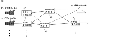
(実施形態3)
本実施形態は、ネットワークスイッチが複数存在する構成である。図7は、映像送信のための帯域が1つのネットワークパスで確保できない場合の構成例である。図7の長距離映像伝送システムは2台のOpenFlowスイッチを使用し、2つの経路で映像パケットを伝送する。2台のOpenFlowスイッチを使用する場合は、制御メッセージを全てのOpenFlowスイッチに対して送信し、切り替えを行う。
(Embodiment 3)
In the present embodiment, there are a plurality of network switches. FIG. 7 shows a configuration example when a band for video transmission cannot be secured by one network path. The long distance video transmission system of FIG. 7 uses two OpenFlow switches and transmits video packets through two paths. When two OpenFlow switches are used, a control message is transmitted to all OpenFlow switches to perform switching.
遅延時間検出手順では、RTTをスイッチ毎に評価する。つまり、IP映像変換装置4と映像IP変換装置(2A、2B)の間のRTTとして、OpenFlowスイッチ3A経由のRTTとOpenFlowスイッチ3B経由のRTTを評価しておく。本実施形態では、事前に評価したRTTを次のように記載する。
T42A_3A:OpenFlowスイッチ3A経由のIP映像変換装置4と映像IP変換装置2Aとの間のRTT
T42A_3B:OpenFlowスイッチ3B経由のIP映像変換装置4と映像IP変換装置2Aとの間のRTT
T42B_3A:OpenFlowスイッチ3A経由のIP映像変換装置4と映像IP変換装置2Bとの間のRTT
T42B_3B:OpenFlowスイッチ3B経由のIP映像変換装置4と映像IP変換装置2Bとの間のRTT
T52A_3A:OpenFlowスイッチ3A経由の受信制御端末5と映像IP変換装置2Aとの間のRTT
T52A_3B:OpenFlowスイッチ3B経由の受信制御端末5と映像IP変換装置2Aとの間のRTT
T52B_3A:OpenFlowスイッチ3A経由の受信制御端末5と映像IP変換装置2Bとの間のRTT
T52B_3B:OpenFlowスイッチ3B経由の受信制御端末5と映像IP変換装置2Bとの間のRTT
T53A:受信制御端末5とOpenFlowスイッチ3Aとの間のRTT
T53B:受信制御端末5とOpenFlowスイッチ3Bとの間のRTT
T43A:IP映像変換装置4とOpenFlowスイッチ3Aとの間のRTT
T43B:IP映像変換装置4とOpenFlowスイッチ3Bとの間のRTT
In the delay time detection procedure, RTT is evaluated for each switch. That is, the RTT via the
T42A_3A: RTT between the IP
T42A_3B: RTT between the IP
T42B_3A: RTT between the IP
T42B_3B: RTT between the IP
T52A_3A: RTT between the
T52A_3B: RTT between the
T52B_3A: RTT between the
T52B_3B: RTT between the
T53A: RTT between the
T53B: RTT between the
T43A: RTT between the IP
T43B: RTT between the IP
(実施形態3−1)
本実施形態は実施形態1で説明した映像切替方式の長距離映像伝送システムである。それぞれの遅延時間を元に切り替え時間に先立って受信制御端末5からメッセージ(送信開始指示、切替指示、送信停止指示)を送ればよい。例えば、受信制御端末5は、“映像送信開始指示”を(式1)によって計算される映像切り替え時刻よりも前に映像IP変換装置2Bに映像送信開始をネットワーク経由で指示する。この場合、(式1)のT52BにはT52B_3AおよびT52B_3Bのうちの大きい方の値を使用し、T42BにはT42B_3AおよびT42B_3Bのうちの大きい方の値を使用する。大きい方の値を使用することによって、送信開始が遅くなってアンダーフローを起こすことを防ぐことができる。
(Embodiment 3-1)
This embodiment is the long-distance video transmission system of the video switching method described in the first embodiment. A message (transmission start instruction, switching instruction, transmission stop instruction) may be sent from the
また、受信制御端末5は、“切替指示”を2つのOpenFlowスイッチ(3A、3B)に対して、それぞれ、
時刻{T0−(1/2×T53A+1/2×T43A)} (式9)
時刻{T0−(1/2×T53B+1/2×T43B)} (式10)
に送信する。
In addition, the
Time {T0− (1/2 × T53A + 1/2 × T43A)} (Formula 9)
Time {T0− (1/2 × T53B + 1/2 × T43B)} (Formula 10)
Send to.
(実施形態3−2)
本実施形態は実施形態2で説明した映像切替方式の長距離映像伝送システムである。それぞれの遅延時間を元に切り替え時間に先立って受信制御端末5からメッセージ(フィードバック切替指示、切替指示)を送ればよい。例えば、受信制御端末5は、“フィードバック切替指示”を2つのOpenFlowスイッチ(3A、3B)に対して、それぞれ、
時刻{T0−(1/2×T53A+T42B−1/2×T43A)} (式11)
時刻{T0−(1/2×T53B+T42B−1/2×T43B)} (式12)
に送信する。ここでT42BはT42B_3AとT42B_3Bのうちの大きい方の値を使用する。
Embodiment 3-2
This embodiment is the long-distance video transmission system of the video switching method described in the second embodiment. Based on each delay time, a message (feedback switching instruction, switching instruction) may be sent from the
Time {T0− (1/2 × T53A + T42B−1 / 2 × T43A)} (Formula 11)
Time {T0− (1/2 × T53B + T42B−1 / 2 × T43B)} (Formula 12)
Send to. Here, T42B uses the larger value of T42B_3A and T42B_3B.
その後、受信制御端末5からOpenFlowスイッチ(3A、3B)に対して、それぞれ、
時刻{T0−(1/2×T53A+1/2×T43A)} (式13)
時刻{T0−(1/2×T53B+1/2×T43B)} (式14)
に、“映像転切替指示”を行えばよい。
Thereafter, from the
Time {T0− (1/2 × T53A + 1/2 × T43A)} (Formula 13)
Time {T0− (1/2 × T53B + 1/2 × T43B)} (Formula 14)
In addition, “video transfer switching instruction” may be performed.
これらの例では、OpenFlowスイッチは2台であるが、3台、4台と増やしても、同じ手法で切り替えることにより切り替えを実現することが可能となる。 In these examples, there are two OpenFlow switches, but even if the number is increased to three or four, switching can be realized by switching in the same manner.
(実施形態4)
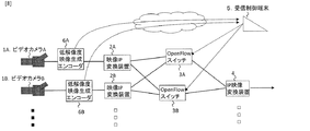
図8は、本実施形態の長距離映像伝送システムを説明する構成図である。図8の長距離映像伝送システムは、図7の長距離映像伝送システムに、新たに低解像度映像生成用エンコーダ(6A、6B)を加えている。
本長距離映像伝送システムは、
前記制御端末と前記低解像度映像生成エンコーダとの間の遅延時間を測定する第2の遅延時間検出手順と、
低解像度映像生成エンコーダで前記映像信号を低解像度化した低解像度映像を前記制御端末が受信する低解像度映像受信手順と、
1の前記パケット化装置と前記復号装置との間の遅延時間と1の前記ネットワークスイッチと前記復号装置との間の遅延時間とから1の前記パケット化装置と1の前記ネットワークスイッチとの間の1の計算遅延時間を計算し、前記1の計算遅延時間を、前記制御端末と1の前記ネットワークスイッチとの間の遅延時間と前記制御端末と1の前記低解像度映像生成エンコーダとの間の遅延時間との和から差し引いた時間と、他の前記パケット化装置と前記復号装置との間の遅延時間と他の前記ネットワークスイッチと前記復号装置との間の遅延時間とから他の前記パケット化装置と他の前記ネットワークスイッチとの間の他の計算遅延時間を計算し、前記他の計算遅延時間を、前記制御端末と他の前記ネットワークスイッチとの間の遅延時間と前記制御端末と他の前記低解像度映像生成エンコーダとの間の遅延時間との和から差し引いた時間のうち大きい方の遅延時間で1の前記パケット化装置及び他の前記パケット化装置に入力する映像信号を遅延させる映像信号遅延手順と、
をさらに行う。
(Embodiment 4)
FIG. 8 is a configuration diagram illustrating the long-distance video transmission system according to the present embodiment. The long-distance video transmission system in FIG. 8 newly adds low-resolution video generation encoders (6A, 6B) to the long-distance video transmission system in FIG.
This long-distance video transmission system
A second delay time detection procedure for measuring a delay time between the control terminal and the low-resolution video generation encoder;
A low-resolution video reception procedure in which the control terminal receives a low-resolution video obtained by reducing the resolution of the video signal by a low-resolution video generation encoder;
Between one packetizer and one network switch from one delay between the packetizer and the decoder and one delay between the network switch and the
Do further.
[第2の遅延時間検出手順]
本長距離映像伝送システムは、前記制御端末と前記低解像度映像生成エンコーダとの間の遅延時間を測定する第2の遅延時間検出手順を行う。
具体的には、本長距離映像伝送システムは、切り替えに先立ち、さらに、受信制御端末5と低解像度映像生成用エンコーダ(6A、6B)との間のRTTを事前に評価する。本実施形態では、事前に評価したRTTを次のように記載する。
T56A:受信制御端末5と低解像度映像生成用エンコーダ6Aとの間のRTT
T56B:受信制御端末5と低解像度映像生成用エンコーダ6Bとの間のRTT
[低解像度映像受信手順]
低解像度映像生成用エンコーダ(6A、6B)は、ビデオカメラ(1A,1B)からの映像をリアルタイムに低いビットレートの映像ストリームに変換し、受信制御端末5にネットワークを経由して送る。
[遅延時間演算手順]
そして、低解像度映像生成用エンコーダ(6A、6B)は、低解像度映像生成用エンコーダ(6A、6B)から受信制御端末に映像が表示され、さらに、その映像を見て、切り替え指示がOpenFlowスイッチ(3A,3B)までに届くのに必要な、以下の式で計算される時間
(1/2×T53A+1/2×T56A) (式15)
(1/2×T53B+1/2×T56B) (式16)
から、以下の式で計算される映像IP変換装置(2A、2B)とOpenFlowスイッチ(3A,3B)間の片道遅延時間
(1/2×T42A−1/2×T43A) (式17)
(1/2×T42B−1/2×T43B) (式18)
を差し引くことによって、計算される時間差、つまり、
(1/2×T53A+1/2×T56A−1/2×T42A+1/2×T43A)
(式19)
(1/2×T53B+1/2×T56B−1/2×T42B+1/2×T43B)
(式20)
のうち大きい方を(必要に応じてエンコード処理時間および後述する受信端末上のデコード時間を加え)遅延として選択する。これにより、あるシーンの映像が受信制御端末5に表示された時点で受信制御端末5から送信された切り替え指示の制御メッセージがOpenFlowスイッチ(3A,3B)に届くのと同じタイミングで、映像IP変換装置(2A、2B)から送信された受信制御端末5で表示された同じシーンの映像信号がOpenFlowスイッチ(3A,3B)に届くこととなる。
[映像信号遅延手順]
低解像度映像生成用エンコーダ(6A、6B)は、ビデオカメラ(1A,1B)からの映像を当該遅延量だけ遅延させて映像IP変換装置(2A、2B)に送る。
[Second delay time detection procedure]
The long distance video transmission system performs a second delay time detection procedure for measuring a delay time between the control terminal and the low resolution video generation encoder.
Specifically, prior to switching, the long distance video transmission system further evaluates the RTT between the
T56A: RTT between the
T56B: RTT between the
[Low-resolution video reception procedure]
The low-resolution video generation encoder (6A, 6B) converts the video from the video camera (1A, 1B) into a video stream with a low bit rate in real time and sends it to the
[Delay time calculation procedure]
Then, the low-resolution video generation encoder (6A, 6B) displays the video from the low-resolution video generation encoder (6A, 6B) on the reception control terminal, and further, when viewing the video, the switching instruction is an OpenFlow switch ( 3A, 3B), the time calculated by the following formula (1/2 × T53A + 1/2 × T56A) (Formula 15)
(1/2 × T53B + 1/2 × T56B) (Formula 16)
Thus, the one-way delay time (1/2 × T42A−1 / 2 × T43A) between the video IP converter (2A, 2B) and the OpenFlow switch (3A, 3B) calculated by the following equation (Equation 17)
(1/2 × T42B−1 / 2 × T43B) (Formula 18)
Subtracting the calculated time difference, i.e.
(1/2 * T53A + 1/2 * T56A-1 / 2 * T42A + 1/2 * T43A)
(Formula 19)
(1/2 × T53B + 1/2 × T56B−1 / 2 × T42B + 1/2 × T43B)
(Formula 20)
The larger one of them is selected as the delay (adding the encoding processing time and the decoding time on the receiving terminal described later if necessary). As a result, the video IP conversion is performed at the same timing when the switching instruction control message transmitted from the
[Video signal delay procedure]
The low-resolution video generation encoder (6A, 6B) delays the video from the video camera (1A, 1B) by the delay amount and sends it to the video IP converter (2A, 2B).
受信制御端末5は受信した低解像度映像をデコードして画面上に出力する。エンコード時間およびデコード時間が無視できないくらい大きい場合は、低解像度映像生成用エンコーダ(6A、6B)で挿入する遅延時間にこれらの処理時間も遅延として挿入する。
The
この処理によって、受信制御端末5上に表示されている映像は、IP映像変換装置4が出力する映像より所定時間だけ早く出力される。当該所定時間は、式19と式20から、それぞれ低解像度映像生成用エンコーダ(6A、6B)と受信制御端末5との間の片道遅延時間1/2×T56Aと1/2×T56Bを引き、さらにOpenFlowスイッチ(3A,3B)からIP映像変換装置4までの片道遅延時間1/2×T43Aと1/2×T43Bを加えた時間
(1/2×T53A−1/2×T42A+T43A) (式21)
(1/2×T53B−1/2×T42B+T43B) (式22)
のうち大きい方の時間である。そこで、運用者は受信制御端末5上の映像を見ながら切り替えを実行すれば、切り替えたいシーンで映像を切り替えることができる。
By this processing, the video displayed on the
(1/2 × T53B−1 / 2 × T42B + T43B) (Formula 22)
The larger of the times. Therefore, if the operator performs switching while watching the video on the
[付記]
以下は、本実施形態の映像ネットワークスイッチング方法を説明したものである。
〔課題〕
遅延のあるネットワークを使って、ネットワーク内で伝送する映像の選択(切り替え)を実現する際に、スムーズな切り替えを実現する手段を提供し、不必要な映像伝送を回避することを目的としている。
〔課題解決の手段〕
本映像ネットワークスイッチング方法は、OpenFlowスイッチなどのIPパケットのヘッダ書き換えと破棄が、ネットワークを経由して実行可能なネットワークスイッチやルータを使ってネットワーク内で転送するIPパケットを選択するとともに、送信装置を最適なタイミングで制御することによって、映像切り替え時の映像の途切れを最小にすることによって前述した課題を解決するものである。
[Appendix]
The following describes the video network switching method of the present embodiment.
〔Task〕
An object of the present invention is to provide a means for realizing smooth switching when avoiding unnecessary video transmission when realizing selection (switching) of a video to be transmitted in the network using a network having a delay.
[Means for solving problems]
In this video network switching method, the IP packet header rewriting and discarding of the OpenFlow switch or the like selects the IP packet to be transferred within the network using a network switch or router that can be executed via the network, and the transmission device By controlling at the optimum timing, the above-mentioned problems are solved by minimizing the interruption of the video at the video switching time.
(1):
映像信号をネットワークで送信可能なパケットに変換し、ネットワークに対してパケットに変換された映像を送信する機能を持つパケット化装置複数台と、1または複数台のネットワーク経由で制御可能なネットワークスイッチと、パケット化された映像パケットを映像信号に復号する復号装置と、これらの装置をつなぐネットワーク、およびこれらの装置を制御する制御端末から構成される映像ネットワークシステムにおいて、
各装置間の遅延を測定する段階と、
測定された遅延時間から計算された時間先行して、前記パケット化装置のうち送信処理を実行していないものに対して、送信開始メッセージを送信し、送信を開始させる段階と、
前記送信開始メッセージを受信した前記パケット化装置が映像パケットの送信を開始する段階と、
測定された遅延時間から計算された時間先行して、前記全てのネットワークスイッチに対して、転送するパケットを切り替える切替指示メッセージを送信する段階と、
前記切替指示メッセージを受信した前記ネットワークスイッチが復号装置に転送するパケットを変更する段階と、
から構成される映像ネットワークスイッチング方法。
(1):
A plurality of packetizing devices having a function of converting video signals into packets that can be transmitted over a network and transmitting the video converted into packets to the network; and a network switch that can be controlled via one or more networks In a video network system including a decoding device that decodes packetized video packets into a video signal, a network that connects these devices, and a control terminal that controls these devices,
Measuring the delay between each device;
Preceding the time calculated from the measured delay time, sending a transmission start message to the packetizer that has not performed transmission processing, and starting transmission;
The packetizing device that has received the transmission start message starts transmitting a video packet;
Sending a switching instruction message for switching a packet to be transferred to all the network switches in advance of a time calculated from the measured delay time;
The network switch that has received the switching instruction message changes a packet transferred to a decoding device;
A video network switching method comprising:
(2):
上記(1)記載の映像ネットワークスイッチング方法において、
前記送信開始メッセージを、前記パケット化装置と前記制御端末との間の遅延時間および前記パケット化装置と前記復号装置間の遅延時間を元に計算された時間先行して、送信し、
前記切替指示メッセージを、前記ネットワークスイッチと前記制御端末との間の遅延時間および前記ネットワークスイッチと前記復号装置間の遅延時間を元に計算された時間先行して、送信する
ことを特徴とする映像ネットワークスイッチング方法。
(2):
In the video network switching method according to (1) above,
Transmitting the transmission start message in advance of a time calculated based on a delay time between the packetizer and the control terminal and a delay time between the packetizer and the decoder;
The switching instruction message is transmitted in advance of a time calculated based on a delay time between the network switch and the control terminal and a delay time between the network switch and the decoding device. Network switching method.
(3):
上記(1)記載の映像ネットワークシステムのうち、前記復号装置からのフィードバックパケットによって送信を開始することができるパケット化装置を使用した映像ネットワークシステムにおいて、
各装置間の遅延を測定する段階と、測定された遅延時間から計算された時間先行して、前記全てのネットワークスイッチに対して前記復号装置からの前記フィードバックパケットの転送先を変更するフィードバック切替指示メッセージを送信する段階と、
前記フィードバック切替指示メッセージを受信した前記ネットワークスイッチが前記フィードバックパケットを転送する先を変更する段階と、
測定された遅延時間から計算された時間先行して前記ネットワークスイッチに対して、フィードバック切替指示メッセージにより指定された転送先からの映像パケットを前記復号装置に転送し、これまで転送していた映像パケットの転送を停止するための切替指示メッセージを送信する段階と、
前記切替指示メッセージを受信した前記ネットワークスイッチが転送する映像パケットを変更する段階と、
から構成される映像ネットワークスイッチング方法。
(3):
Among the video network systems described in (1) above, in a video network system using a packetizing device capable of starting transmission by a feedback packet from the decoding device,
A step of measuring a delay between the devices, and a feedback switching instruction for changing a transfer destination of the feedback packet from the decoding device to all the network switches in advance of a time calculated from the measured delay time Sending a message;
Receiving the feedback switching instruction message, changing the destination to which the network switch forwards the feedback packet;
The video packet from the transfer destination designated by the feedback switching instruction message is forwarded to the network switch before the time calculated from the measured delay time, and the video packet transferred so far Sending a switch instruction message to stop the transfer of
Changing the video packet transferred by the network switch that has received the switching instruction message;
A video network switching method comprising:
(4):
上記(3)記載のネットワークスイッチング方法において、
前記フィードバック切替指示メッセージを、前記ネットワークスイッチと前記復号装置間の遅延時間および前記ネットワークスイッチと前記制御端末間の遅延時間を元に計算される時間先行して、送信し、
前記切替指示メッセージを、前記ネットワークスイッチと前記制御端末との間の遅延時間および前記ネットワークスイッチと前記復号装置間の遅延時間を元に計算された時間先行して、送信する
ことを特徴とする映像ネットワークスイッチング方法。
(4):
In the network switching method according to (3) above,
Transmitting the feedback switching instruction message in advance of a time calculated based on a delay time between the network switch and the decoding device and a delay time between the network switch and the control terminal;
The switching instruction message is transmitted in advance of a time calculated based on a delay time between the network switch and the control terminal and a delay time between the network switch and the decoding device. Network switching method.
(5):
上記(1)または(3)記載の映像ネットワークシステムに対して、
パケット化する映像と同じ映像を制御端末で視聴可能なフォーマットの映像(以下、低解像度映像)に変換するとともに、制御端末に送る装置(以下、低解像度映像変換装置)を複数台追加した映像ネットワークシステムにおいて、
上記(1)ないし(4)記載の映像ネットワークスイッチング方法に対して、各装置間の遅延を測定する段階の後に、測定された遅延時間から計算された時間分パケット化装置に映像信号を送るタイミングを遅らせる段階を加えた、映像ネットワークスイッチング方法。
(5):
For the video network system described in (1) or (3) above,
A video network in which the same video as the packetized video is converted to video in a format that can be viewed on the control terminal (hereinafter referred to as low resolution video) and a plurality of devices (hereinafter referred to as low resolution video conversion devices) that are sent to the control terminal In the system,
In the video network switching method according to the above (1) to (4), after the step of measuring the delay between the devices, the timing of sending the video signal to the packetizing device by the time calculated from the measured delay time A video network switching method that adds a delay stage.
〔効果〕
本映像ネットワークスイッチング方法は、遠隔地から伝送されてきた映像をネットワーク内で選択可能にすることによって、無駄な映像伝送を回避し、ネットワーク帯域を節約し、映像伝送に関わるコストを削減する効果を提供することができる。
〔effect〕
This video network switching method has the effect of avoiding useless video transmission, saving network bandwidth, and reducing costs related to video transmission by enabling selection of video transmitted from a remote location within the network. Can be provided.
本実施形態では、ネットワークスイッチとしてOpenFlowスイッチを使用して説明を行ったが、ネットワークを介して遠隔で制御でき、かつ、任意のIPアドレスからのパケットの破棄およびIPパケットのアドレス変換(Network Address Translation)機能を持っているブロードバンドルータやネットワークスイッチであれば本実施形態の長距離映像伝送システムに利用可能である。 In the present embodiment, the description has been given using the OpenFlow switch as the network switch. However, the network switch can be remotely controlled via the network, and discards a packet from an arbitrary IP address and converts an IP packet address (Network Address Translation). Any broadband router or network switch having a function can be used in the long-distance video transmission system of this embodiment.
1A、1B:ビデオカメラ、映像送信装置
2A、2B:映像IP変換装置
3、3A、3B:OpenFlowスイッチ
4:IP映像変換装置
5:受信制御端末
6A、6B:低解像度映像生成用エンコーダ
7:映像受信装置
8:映像スイッチャ
1A, 1B: Video camera,
Claims (7)
前記パケット化装置からの映像パケットを透過又は廃棄する1または複数のネットワークスイッチと、
前記ネットワークから映像パケットを受信して映像信号に復号する復号装置と、
前記ネットワーク経由で前記パケット化装置及び前記ネットワークスイッチの動作を制御する制御端末と、
を備える通信システムの制御方法であって、
前記制御端末と前記ネットワークスイッチとの間の遅延時間、前記パケット化装置と前記復号装置との間の遅延時間、前記制御端末と前記パケット化装置との間の遅延時間、及び前記ネットワークスイッチと前記復号装置との間の遅延時間を測定する遅延時間検出手順と、
1の前記パケット化装置からの映像パケットを前記ネットワークスイッチが透過させて前記復号装置が前記映像パケットを受信しているときに、前記遅延時間検出手順で測定した遅延時間に基づき他の前記パケット化装置からの映像パケットを前記復号装置が受信するであろう時刻が切替完了時刻より前となるように、前記制御端末が他の前記パケット化装置へ映像パケットを送信させる送信開始指示を行う送信開始手順と、
前記送信開始手順の後、他の前記パケット化装置からの映像パケットを前記ネットワークスイッチが廃棄しているときに、前記遅延時間検出手順で測定した遅延時間に基づき前記切替完了時刻に他の前記パケット化装置からの映像パケットを前記復号装置が受信するように、1の前記パケット化装置からの映像パケットを廃棄して他の前記パケット化装置からの映像パケットを透過する映像切替指示を前記制御端末が前記ネットワークスイッチへ行う映像切替指示手順と、
前記映像切替指示手順の後、1の前記パケット化装置へ映像パケットの送信を停止させる送信停止指示を行う送信停止指示手順と、
を行う通信システムの制御方法。 A plurality of packetizing devices for converting video signals into video packets that can be transmitted over a network and transmitting the video packets to the network;
One or more network switches for transmitting or discarding video packets from the packetizer;
A decoding device that receives video packets from the network and decodes them into video signals;
A control terminal for controlling the operation of the packetizer and the network switch via the network;
A communication system control method comprising:
A delay time between the control terminal and the network switch, a delay time between the packetizer and the decoder, a delay time between the control terminal and the packetizer, and the network switch and the A delay time detection procedure for measuring a delay time with the decoding device;
When the network switch transmits the video packet from one of the packetizing devices and the decoding device receives the video packet, the other packetization is performed based on the delay time measured in the delay time detection procedure. Transmission start in which the control terminal issues a transmission start instruction to transmit the video packet to the other packetizing device so that the time at which the decoding device will receive the video packet from the device is before the switching completion time Procedure and
After the transmission start procedure, when the network switch discards the video packet from the other packetizing device, the other packet at the switching completion time based on the delay time measured in the delay time detection procedure. In order for the decoding device to receive the video packet from the packetizing device, the control terminal issues a video switching instruction that discards the video packet from one packetizing device and transmits the video packet from the other packetizing device. A video switching instruction procedure performed by the network switch;
A transmission stop instruction procedure for performing a transmission stop instruction to stop transmission of a video packet to one of the packetizers after the video switching instruction procedure;
A control method for a communication system.
前記映像切替指示手順では、前記切替完了時刻、前記制御端末と前記ネットワークスイッチとの間の遅延時間及び前記ネットワークスイッチと前記復号装置との間の遅延時間から計算した時刻に前記映像切替指示を行う
ことを特徴とする請求項1に記載の通信システムの制御方法。 In the transmission start procedure, the transmission starts before the time calculated from the switching completion time, the delay time between the control terminal and the packetizer, and the delay time between the packetizer and the decoder. Give instructions,
In the video switching instruction procedure, the video switching instruction is performed at a time calculated from the switching completion time, a delay time between the control terminal and the network switch, and a delay time between the network switch and the decoding device. The communication system control method according to claim 1.
前記パケット化装置からの映像パケットを透過又は廃棄する1または複数のネットワークスイッチと、
前記ネットワークから映像パケットを受信して映像信号に復号する復号装置と、
前記ネットワーク経由で前記ネットワークスイッチの動作を制御する制御端末と、
を備え、
前記復号装置からの定期的なフィードバックパケットを受信することで前記パケット化装置が映像パケットを送信する通信システムの制御方法であって、
前記制御端末と前記ネットワークスイッチとの間の遅延時間、前記パケット化装置と前記復号装置との間の遅延時間、及び前記ネットワークスイッチと前記復号装置との間の遅延時間を測定する遅延時間検出手順と、
1の前記パケット化装置からの映像パケットを前記ネットワークスイッチが透過させて前記復号装置が前記映像パケットを受信しているときに、前記遅延時間検出手順で測定した遅延時間に基づき他の前記パケット化装置からの映像パケットを前記復号装置が受信するであろう時刻が切替完了時刻より前となるように、前記制御端末が前記ネットワークスイッチへ前記フィードバックパケットの宛先を1の前記パケット化装置から他の前記パケット化装置へ書き換えるフィードバック切替指示を行うフィードバック切替指示手順と、
前記フィードバック切替指示手順の後、前記遅延時間検出手順で測定した遅延時間に基づき前記切替完了時刻に他の前記パケット化装置からの映像パケットを前記復号装置が受信するように、1の前記パケット化装置からの映像パケットを廃棄して他の前記パケット化装置からの映像パケットを透過する映像切替指示を前記制御端末が前記ネットワークスイッチへ行う映像切替指示手順と、
を行う通信システムの制御方法。 A plurality of packetizing devices for converting video signals into video packets that can be transmitted over a network and transmitting the video packets to the network;
One or more network switches for transmitting or discarding video packets from the packetizer;
A decoding device that receives video packets from the network and decodes them into video signals;
A control terminal for controlling the operation of the network switch via the network;
With
A control method of a communication system in which the packetizing device transmits a video packet by receiving a periodic feedback packet from the decoding device,
Delay time detection procedure for measuring a delay time between the control terminal and the network switch, a delay time between the packetizer and the decoder, and a delay time between the network switch and the decoder When,
When the network switch transmits the video packet from one of the packetizing devices and the decoding device receives the video packet, the other packetization is performed based on the delay time measured in the delay time detection procedure. The control terminal sends the destination of the feedback packet from the one packetizer to the network switch so that the time at which the decoding device will receive the video packet from the device is before the switching completion time. A feedback switching instruction procedure for performing a feedback switching instruction to be rewritten to the packetizer;
After the feedback switching instruction procedure, one packetization is performed so that the decoding device receives a video packet from another packetization device at the switching completion time based on the delay time measured in the delay time detection procedure. A video switching instruction procedure in which the control terminal sends a video switching instruction to discard the video packet from the apparatus and transmits the video packet from the other packetizing apparatus to the network switch;
A control method for a communication system.
前記映像切替指示手順では、前記切替完了時刻、前記制御端末と前記ネットワークスイッチとの間の遅延時間及び前記ネットワークスイッチと前記復号装置との間の遅延時間から計算した時刻に前記映像切替指示を行う
ことを特徴とする請求項3に記載の通信システムの制御方法。 In the feedback switching instruction procedure, the switching completion time, the delay time between the decoding device and the packetizing device, the delay time between the network switch and the decoding device, and between the control terminal and the network switch Instruct the feedback switching before the time calculated from the delay time between,
In the video switching instruction procedure, the video switching instruction is performed at a time calculated from the switching completion time, a delay time between the control terminal and the network switch, and a delay time between the network switch and the decoding device. The communication system control method according to claim 3.
低解像度映像生成エンコーダで前記映像信号を低解像度化した低解像度映像を前記制御端末が受信する低解像度映像受信手順と、
1の前記パケット化装置と前記復号装置との間の遅延時間と1の前記ネットワークスイッチと前記復号装置との間の遅延時間とから1の前記パケット化装置と1の前記ネットワークスイッチとの間の1の計算遅延時間を計算し、前記1の計算遅延時間を、前記制御端末と1の前記ネットワークスイッチとの間の遅延時間と前記制御端末と1の前記低解像度映像生成エンコーダとの間の遅延時間との和から差し引いた時間と、他の前記パケット化装置と前記復号装置との間の遅延時間と他の前記ネットワークスイッチと前記復号装置との間の遅延時間とから他の前記パケット化装置と他の前記ネットワークスイッチとの間の他の計算遅延時間を計算し、前記他の計算遅延時間を、前記制御端末と他の前記ネットワークスイッチとの間の遅延時間と前記制御端末と他の前記低解像度映像生成エンコーダとの間の遅延時間との和から差し引いた時間のうち大きい方の遅延時間で1の前記パケット化装置及び他の前記パケット化装置に入力する映像信号を遅延させる映像信号遅延手順と、
をさらに行うことを特徴とする請求項1から4に記載の通信システムの制御方法。 A second delay time detection procedure for measuring a delay time between the control terminal and the low-resolution video generation encoder;
A low-resolution video reception procedure in which the control terminal receives a low-resolution video obtained by reducing the resolution of the video signal by a low-resolution video generation encoder;
Between one packetizer and one network switch from one delay between the packetizer and the decoder and one delay between the network switch and the decoder 1 calculation delay time is calculated, and the 1 calculation delay time is calculated as a delay time between the control terminal and 1 network switch and a delay between the control terminal and 1 low-resolution video generation encoder. The other packetizing apparatus based on the time subtracted from the sum of the time, the delay time between the other packetizing apparatus and the decoding apparatus, and the delay time between the other network switch and the decoding apparatus And the other calculation delay time between the control terminal and the other network switch is calculated. Video input to one packetizer and another packetizer with a larger delay time out of the sum of delay times between the control terminal and the other low-resolution video generation encoder A video signal delay procedure for delaying the signal;
5. The communication system control method according to claim 1, further comprising:
前記パケット化装置からの映像パケットを透過又は廃棄する1または複数のネットワークスイッチと、
前記ネットワークから映像パケットを受信して映像信号に復号する復号装置と、
前記ネットワーク経由で前記パケット化装置及び前記ネットワークスイッチの動作を制御する制御端末と、
を備える通信システムであって、
前記制御端末が請求項1、請求項2、あるいは請求項1又は2を引用する請求項5に記載の通信システムの制御方法を行うことを特徴とする通信システム。 A plurality of packetizing devices for converting video signals into video packets that can be transmitted over a network and transmitting the video packets to the network;
One or more network switches for transmitting or discarding video packets from the packetizer;
A decoding device that receives video packets from the network and decodes them into video signals;
A control terminal for controlling the operation of the packetizer and the network switch via the network;
A communication system comprising:
A communication system, wherein the control terminal performs the control method of the communication system according to claim 1, claim 2, or claim 1 or 2.
前記パケット化装置からの映像パケットを透過又は廃棄する1または複数のネットワークスイッチと、
前記ネットワークから映像パケットを受信して映像信号に復号する復号装置と、
前記ネットワーク経由で前記ネットワークスイッチの動作を制御する制御端末と、
を備え、
前記復号装置からの定期的なフィードバックパケットを受信することで前記パケット化装置が映像パケットを送信する通信システムであって、
前記制御端末が請求項3、請求項4、あるいは請求項3又は4を引用する請求項5に記載の通信システムの制御方法を行うことを特徴とする通信システム。 A plurality of packetizing devices for converting video signals into video packets that can be transmitted over a network and transmitting the video packets to the network;
One or more network switches for transmitting or discarding video packets from the packetizer;
A decoding device that receives video packets from the network and decodes them into video signals;
A control terminal for controlling the operation of the network switch via the network;
With
A communication system in which the packetizer transmits video packets by receiving periodic feedback packets from the decoder,
A communication system, wherein the control terminal performs the communication system control method according to claim 3, claim 4, or claim 5.
Priority Applications (1)
| Application Number | Priority Date | Filing Date | Title |
|---|---|---|---|
| JP2016079250A JP6517167B2 (en) | 2016-04-12 | 2016-04-12 | Control method of communication system and communication system |
Applications Claiming Priority (1)
| Application Number | Priority Date | Filing Date | Title |
|---|---|---|---|
| JP2016079250A JP6517167B2 (en) | 2016-04-12 | 2016-04-12 | Control method of communication system and communication system |
Publications (2)
| Publication Number | Publication Date |
|---|---|
| JP2017191976A true JP2017191976A (en) | 2017-10-19 |
| JP6517167B2 JP6517167B2 (en) | 2019-05-22 |
Family
ID=60086134
Family Applications (1)
| Application Number | Title | Priority Date | Filing Date |
|---|---|---|---|
| JP2016079250A Active JP6517167B2 (en) | 2016-04-12 | 2016-04-12 | Control method of communication system and communication system |
Country Status (1)
| Country | Link |
|---|---|
| JP (1) | JP6517167B2 (en) |
Cited By (1)
| Publication number | Priority date | Publication date | Assignee | Title |
|---|---|---|---|---|
| JP7643023B2 (en) | 2020-12-14 | 2025-03-11 | 日本電気株式会社 | TRANSFER CONTROL DEVICE, TRANSFER CONTROL METHOD, TRANSFER CONTROL PROGRAM, SWITCHING SYSTEM, SWITCHING METHOD, AND TRANSFER SYSTEM |
Citations (4)
| Publication number | Priority date | Publication date | Assignee | Title |
|---|---|---|---|---|
| JP2008278301A (en) * | 2007-05-01 | 2008-11-13 | Nippon Telegr & Teleph Corp <Ntt> | Video transmission / reception system, video switching method, video transmission device, video reception device, and control device |
| JP2009188471A (en) * | 2008-02-04 | 2009-08-20 | Hitachi Communication Technologies Ltd | Optical access network and optical communication path switching control system |
| JP2011160195A (en) * | 2010-02-01 | 2011-08-18 | Nippon Telegr & Teleph Corp <Ntt> | Band allocating device, and band allocating method |
| WO2014162981A1 (en) * | 2013-04-05 | 2014-10-09 | ソニー株式会社 | Controller, control method, computer program, and video transmission system |
-
2016
- 2016-04-12 JP JP2016079250A patent/JP6517167B2/en active Active
Patent Citations (4)
| Publication number | Priority date | Publication date | Assignee | Title |
|---|---|---|---|---|
| JP2008278301A (en) * | 2007-05-01 | 2008-11-13 | Nippon Telegr & Teleph Corp <Ntt> | Video transmission / reception system, video switching method, video transmission device, video reception device, and control device |
| JP2009188471A (en) * | 2008-02-04 | 2009-08-20 | Hitachi Communication Technologies Ltd | Optical access network and optical communication path switching control system |
| JP2011160195A (en) * | 2010-02-01 | 2011-08-18 | Nippon Telegr & Teleph Corp <Ntt> | Band allocating device, and band allocating method |
| WO2014162981A1 (en) * | 2013-04-05 | 2014-10-09 | ソニー株式会社 | Controller, control method, computer program, and video transmission system |
Cited By (1)
| Publication number | Priority date | Publication date | Assignee | Title |
|---|---|---|---|---|
| JP7643023B2 (en) | 2020-12-14 | 2025-03-11 | 日本電気株式会社 | TRANSFER CONTROL DEVICE, TRANSFER CONTROL METHOD, TRANSFER CONTROL PROGRAM, SWITCHING SYSTEM, SWITCHING METHOD, AND TRANSFER SYSTEM |
Also Published As
| Publication number | Publication date |
|---|---|
| JP6517167B2 (en) | 2019-05-22 |
Similar Documents
| Publication | Publication Date | Title |
|---|---|---|
| CA2941430C (en) | Video transmission system and video receiver | |
| US8810668B2 (en) | Camera system, video selection apparatus and video selection method | |
| RU2634206C2 (en) | Device and method of commutation of media streams in real time mode | |
| US10200633B2 (en) | Camera system, video selection apparatus and video selection method | |
| CN101438567B (en) | Method and apparatus for wireless transmission internet protocol television | |
| JP6188092B2 (en) | Information signal transmission / reception method via network, transmitter and receiver using the method, splitter unit for use in the network | |
| JP6517167B2 (en) | Control method of communication system and communication system | |
| Kawamoto et al. | Development of lightweight compressed 8K UHDTV over IP transmission device realizing live remote production | |
| JP4839797B2 (en) | Power line communication apparatus and power line communication method | |
| JP7516309B2 (en) | Content distribution device and content distribution method | |
| WO2016152063A1 (en) | Data reception device, data transmission system, data reception method, and data transmission method | |
| JP5723753B2 (en) | Data transmission system and receiving apparatus | |
| JP5928561B2 (en) | Camera system, video selection device, and video selection method | |
| JP2017092580A (en) | Broadcast receiver, broadcast reception method, and broadcast reception program | |
| JP2006174000A (en) | Network system | |
| JP2018201098A (en) | Video display system | |
| JP2017200134A (en) | Communication device, communication system, communication method, and program | |
| KR20090008472A (en) | Method and device for wireless transmission of internet protocol TV | |
| JP2013110454A (en) | Data transmission system and reception device | |
| WO2008029464A1 (en) | Video transmission star-type network |
Legal Events
| Date | Code | Title | Description |
|---|---|---|---|
| A621 | Written request for application examination |
Free format text: JAPANESE INTERMEDIATE CODE: A621 Effective date: 20180612 |
|
| A977 | Report on retrieval |
Free format text: JAPANESE INTERMEDIATE CODE: A971007 Effective date: 20190117 |
|
| A131 | Notification of reasons for refusal |
Free format text: JAPANESE INTERMEDIATE CODE: A131 Effective date: 20190122 |
|
| A521 | Request for written amendment filed |
Free format text: JAPANESE INTERMEDIATE CODE: A523 Effective date: 20190301 |
|
| TRDD | Decision of grant or rejection written | ||
| A01 | Written decision to grant a patent or to grant a registration (utility model) |
Free format text: JAPANESE INTERMEDIATE CODE: A01 Effective date: 20190416 |
|
| A61 | First payment of annual fees (during grant procedure) |
Free format text: JAPANESE INTERMEDIATE CODE: A61 Effective date: 20190417 |
|
| R150 | Certificate of patent or registration of utility model |
Ref document number: 6517167 Country of ref document: JP Free format text: JAPANESE INTERMEDIATE CODE: R150 |
|
| S533 | Written request for registration of change of name |
Free format text: JAPANESE INTERMEDIATE CODE: R313533 |
|
| R350 | Written notification of registration of transfer |
Free format text: JAPANESE INTERMEDIATE CODE: R350 |