JP2017192219A - 3レベルチョッパ装置 - Google Patents
3レベルチョッパ装置 Download PDFInfo
- Publication number
- JP2017192219A JP2017192219A JP2016080699A JP2016080699A JP2017192219A JP 2017192219 A JP2017192219 A JP 2017192219A JP 2016080699 A JP2016080699 A JP 2016080699A JP 2016080699 A JP2016080699 A JP 2016080699A JP 2017192219 A JP2017192219 A JP 2017192219A
- Authority
- JP
- Japan
- Prior art keywords
- switch
- capacitor
- protection switch
- diode
- protection
- Prior art date
- Legal status (The legal status is an assumption and is not a legal conclusion. Google has not performed a legal analysis and makes no representation as to the accuracy of the status listed.)
- Granted
Links
Images










Classifications
-
- H—ELECTRICITY
- H02—GENERATION; CONVERSION OR DISTRIBUTION OF ELECTRIC POWER
- H02H—EMERGENCY PROTECTIVE CIRCUIT ARRANGEMENTS
- H02H7/00—Emergency protective circuit arrangements specially adapted for specific types of electric machines or apparatus or for sectionalised protection of cable or line systems, and effecting automatic switching in the event of an undesired change from normal working conditions
- H02H7/10—Emergency protective circuit arrangements specially adapted for specific types of electric machines or apparatus or for sectionalised protection of cable or line systems, and effecting automatic switching in the event of an undesired change from normal working conditions for converters; for rectifiers
- H02H7/12—Emergency protective circuit arrangements specially adapted for specific types of electric machines or apparatus or for sectionalised protection of cable or line systems, and effecting automatic switching in the event of an undesired change from normal working conditions for converters; for rectifiers for static converters or rectifiers
- H02H7/122—Emergency protective circuit arrangements specially adapted for specific types of electric machines or apparatus or for sectionalised protection of cable or line systems, and effecting automatic switching in the event of an undesired change from normal working conditions for converters; for rectifiers for static converters or rectifiers for inverters, i.e. DC/AC converters
- H02H7/1227—Emergency protective circuit arrangements specially adapted for specific types of electric machines or apparatus or for sectionalised protection of cable or line systems, and effecting automatic switching in the event of an undesired change from normal working conditions for converters; for rectifiers for static converters or rectifiers for inverters, i.e. DC/AC converters responsive to abnormalities in the output circuit, e.g. short circuit
-
- H—ELECTRICITY
- H02—GENERATION; CONVERSION OR DISTRIBUTION OF ELECTRIC POWER
- H02H—EMERGENCY PROTECTIVE CIRCUIT ARRANGEMENTS
- H02H3/00—Emergency protective circuit arrangements for automatic disconnection directly responsive to an undesired change from normal electric working condition with or without subsequent reconnection ; integrated protection
- H02H3/16—Emergency protective circuit arrangements for automatic disconnection directly responsive to an undesired change from normal electric working condition with or without subsequent reconnection ; integrated protection responsive to fault current to earth, frame or mass
- H02H3/162—Emergency protective circuit arrangements for automatic disconnection directly responsive to an undesired change from normal electric working condition with or without subsequent reconnection ; integrated protection responsive to fault current to earth, frame or mass for AC systems
- H02H3/165—Emergency protective circuit arrangements for automatic disconnection directly responsive to an undesired change from normal electric working condition with or without subsequent reconnection ; integrated protection responsive to fault current to earth, frame or mass for AC systems for three-phase systems
-
- H—ELECTRICITY
- H02—GENERATION; CONVERSION OR DISTRIBUTION OF ELECTRIC POWER
- H02H—EMERGENCY PROTECTIVE CIRCUIT ARRANGEMENTS
- H02H7/00—Emergency protective circuit arrangements specially adapted for specific types of electric machines or apparatus or for sectionalised protection of cable or line systems, and effecting automatic switching in the event of an undesired change from normal working conditions
- H02H7/10—Emergency protective circuit arrangements specially adapted for specific types of electric machines or apparatus or for sectionalised protection of cable or line systems, and effecting automatic switching in the event of an undesired change from normal working conditions for converters; for rectifiers
- H02H7/12—Emergency protective circuit arrangements specially adapted for specific types of electric machines or apparatus or for sectionalised protection of cable or line systems, and effecting automatic switching in the event of an undesired change from normal working conditions for converters; for rectifiers for static converters or rectifiers
- H02H7/122—Emergency protective circuit arrangements specially adapted for specific types of electric machines or apparatus or for sectionalised protection of cable or line systems, and effecting automatic switching in the event of an undesired change from normal working conditions for converters; for rectifiers for static converters or rectifiers for inverters, i.e. DC/AC converters
- H02H7/1222—Emergency protective circuit arrangements specially adapted for specific types of electric machines or apparatus or for sectionalised protection of cable or line systems, and effecting automatic switching in the event of an undesired change from normal working conditions for converters; for rectifiers for static converters or rectifiers for inverters, i.e. DC/AC converters responsive to abnormalities in the input circuit, e.g. transients in the DC input
-
- H—ELECTRICITY
- H02—GENERATION; CONVERSION OR DISTRIBUTION OF ELECTRIC POWER
- H02M—APPARATUS FOR CONVERSION BETWEEN AC AND AC, BETWEEN AC AND DC, OR BETWEEN DC AND DC, AND FOR USE WITH MAINS OR SIMILAR POWER SUPPLY SYSTEMS; CONVERSION OF DC OR AC INPUT POWER INTO SURGE OUTPUT POWER; CONTROL OR REGULATION THEREOF
- H02M3/00—Conversion of DC power input into DC power output
- H02M3/02—Conversion of DC power input into DC power output without intermediate conversion into AC
- H02M3/04—Conversion of DC power input into DC power output without intermediate conversion into AC by static converters
- H02M3/10—Conversion of DC power input into DC power output without intermediate conversion into AC by static converters using discharge tubes with control electrode or semiconductor devices with control electrode
- H02M3/145—Conversion of DC power input into DC power output without intermediate conversion into AC by static converters using discharge tubes with control electrode or semiconductor devices with control electrode using devices of a triode or transistor type requiring continuous application of a control signal
- H02M3/155—Conversion of DC power input into DC power output without intermediate conversion into AC by static converters using discharge tubes with control electrode or semiconductor devices with control electrode using devices of a triode or transistor type requiring continuous application of a control signal using semiconductor devices only
- H02M3/156—Conversion of DC power input into DC power output without intermediate conversion into AC by static converters using discharge tubes with control electrode or semiconductor devices with control electrode using devices of a triode or transistor type requiring continuous application of a control signal using semiconductor devices only with automatic control of output voltage or current, e.g. switching regulators
- H02M3/158—Conversion of DC power input into DC power output without intermediate conversion into AC by static converters using discharge tubes with control electrode or semiconductor devices with control electrode using devices of a triode or transistor type requiring continuous application of a control signal using semiconductor devices only with automatic control of output voltage or current, e.g. switching regulators including plural semiconductor devices as final control devices for a single load
-
- H—ELECTRICITY
- H02—GENERATION; CONVERSION OR DISTRIBUTION OF ELECTRIC POWER
- H02M—APPARATUS FOR CONVERSION BETWEEN AC AND AC, BETWEEN AC AND DC, OR BETWEEN DC AND DC, AND FOR USE WITH MAINS OR SIMILAR POWER SUPPLY SYSTEMS; CONVERSION OF DC OR AC INPUT POWER INTO SURGE OUTPUT POWER; CONTROL OR REGULATION THEREOF
- H02M7/00—Conversion of AC power input into DC power output; Conversion of DC power input into AC power output
- H02M7/42—Conversion of DC power input into AC power output without possibility of reversal
- H02M7/44—Conversion of DC power input into AC power output without possibility of reversal by static converters
- H02M7/48—Conversion of DC power input into AC power output without possibility of reversal by static converters using discharge tubes with control electrode or semiconductor devices with control electrode
- H02M7/53—Conversion of DC power input into AC power output without possibility of reversal by static converters using discharge tubes with control electrode or semiconductor devices with control electrode using devices of a triode or transistor type requiring continuous application of a control signal
- H02M7/537—Conversion of DC power input into AC power output without possibility of reversal by static converters using discharge tubes with control electrode or semiconductor devices with control electrode using devices of a triode or transistor type requiring continuous application of a control signal using semiconductor devices only, e.g. single switched pulse inverters
-
- H—ELECTRICITY
- H02—GENERATION; CONVERSION OR DISTRIBUTION OF ELECTRIC POWER
- H02P—CONTROL OR REGULATION OF ELECTRIC MOTORS, ELECTRIC GENERATORS OR DYNAMO-ELECTRIC CONVERTERS; CONTROLLING TRANSFORMERS, REACTORS OR CHOKE COILS
- H02P29/00—Arrangements for regulating or controlling electric motors, appropriate for both AC and DC motors
- H02P29/02—Providing protection against overload without automatic interruption of supply
- H02P29/024—Detecting a fault condition, e.g. short circuit, locked rotor, open circuit or loss of load
- H02P29/0241—Detecting a fault condition, e.g. short circuit, locked rotor, open circuit or loss of load the fault being an overvoltage
-
- H—ELECTRICITY
- H02—GENERATION; CONVERSION OR DISTRIBUTION OF ELECTRIC POWER
- H02H—EMERGENCY PROTECTIVE CIRCUIT ARRANGEMENTS
- H02H7/00—Emergency protective circuit arrangements specially adapted for specific types of electric machines or apparatus or for sectionalised protection of cable or line systems, and effecting automatic switching in the event of an undesired change from normal working conditions
- H02H7/08—Emergency protective circuit arrangements specially adapted for specific types of electric machines or apparatus or for sectionalised protection of cable or line systems, and effecting automatic switching in the event of an undesired change from normal working conditions for dynamo-electric motors
Landscapes
- Engineering & Computer Science (AREA)
- Power Engineering (AREA)
- Dc-Dc Converters (AREA)
- Inverter Devices (AREA)
Abstract
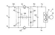
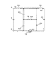
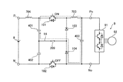
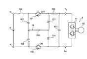
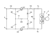
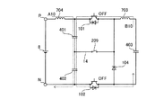
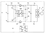
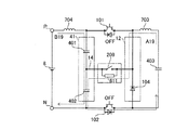
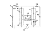
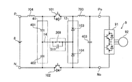
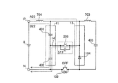
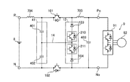
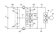
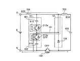
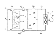
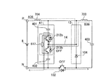
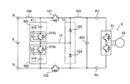
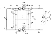
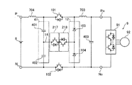
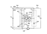
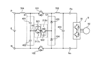
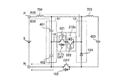
【解決手段】この3レベルチョッパ装置は、スイッチ101およびダイオード103のうちの少なくとも一方、または、スイッチ102およびダイオード104のうちの少なくとも一方の故障時に、コンデンサ402、または、コンデンサ401に過電圧が印加される電流経路を、過電圧とならない電流経路へと変更するように制御可能に構成されている。
【選択図】図1
Description
R≧2×(2×L/C)1/2 ・・・(1)
Ra≧2×(2×L/C2)1/2 ・・・(2)
Rb≧2×(2×L/C1)1/2 ・・・(3)
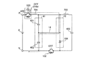
次に、第1実施形態による3レベルチョッパ装置について説明する。
次に、3レベルチョッパ装置の動作(制御方法)について、詳細に説明する。
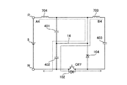
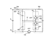
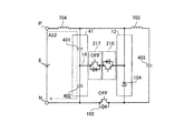
次に、3レベルチョッパ装置において、スイッチ、ダイオードが短絡故障したときの挙動について、詳細に説明する。
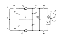
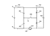
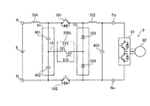
次に、第2実施形態による3レベルチョッパ装置について説明する。
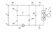
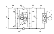
次に、第3実施形態による3レベルチョッパ装置について説明する。
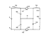
次に、第4実施形態による3レベルチョッパ装置について説明する。
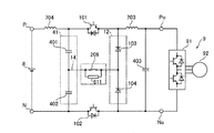
次に、第5実施形態による3レベルチョッパ装置について説明する。
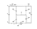
次に、第6実施形態による3レベルチョッパ装置について説明する。
次に、第7実施形態による3レベルチョッパ装置について説明する。
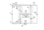
次に、第8実施形態による3レベルチョッパ装置について説明する。
次に、第9実施形態による3レベルチョッパ装置について説明する。
次に、第10実施形態による3レベルチョッパ装置について説明する。
次に、第11実施形態による3レベルチョッパ装置について説明する。
次に、第12実施形態による3レベルチョッパ装置について説明する。
Ra≧2×(2×L/C2)1/2 ・・・(4)
Rb≧2×(2×L/C1)1/2 ・・・(5)
次に、第13実施形態による3レベルチョッパ装置について説明する。
R≧2×(2×L/C2)1/2 ・・・(6)
R≧2×(2×L/C)1/2 ・・・(7)
次に、第14実施形態による3レベルチョッパ装置について説明する。
次に、第15実施形態による3レベルチョッパ装置について説明する。
次に、第16実施形態による3レベルチョッパ装置について説明する。
次に、第17実施形態による3レベルチョッパ装置について説明する。
次に、第18実施形態による3レベルチョッパ装置について説明する。
次に、第19実施形態による3レベルチョッパ装置について説明する。
R≧2×(2×L/C2)1/2 ・・・(8)
R≧2×(2×L/C)1/2 ・・・(9)
次に、第20実施形態による3レベルチョッパ装置について説明する。
次に、第21実施形態による3レベルチョッパ装置について説明する。
次に、第22実施形態による3レベルチョッパ装置について説明する。
次に、第23実施形態による3レベルチョッパ装置について説明する。
なお、今回開示された実施形態は、すべての点で例示であって制限的なものではないと考えられるべきである。本発明の範囲は、上記した実施形態の説明ではなく特許請求の範囲によって示され、さらに特許請求の範囲と均等の意味および範囲内でのすべての変更(変形例)が含まれる。
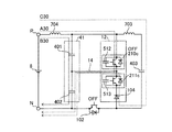
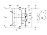
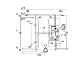
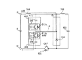
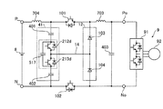
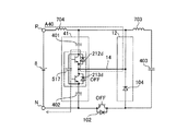
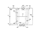
14 接続経路
101 スイッチ(第1のスイッチ)
102 スイッチ(第2のスイッチ)
103 ダイオード(第1のダイオード)
104 ダイオード(第2のダイオード)
209、209a、209b、209c 保護スイッチ(双方向保護スイッチ)
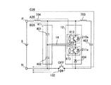
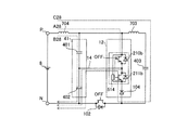
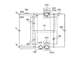
210b 保護スイッチ(第1の保護スイッチ)
211b 保護スイッチ(第2の保護スイッチ)
210d 保護スイッチ(第3の保護スイッチ)
211d 保護スイッチ(第4の保護スイッチ)
212b 保護スイッチ(第5の保護スイッチ)
213b 保護スイッチ(第6の保護スイッチ)
212d 保護スイッチ(第7の保護スイッチ)
213d 保護スイッチ(第8の保護スイッチ)
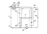
216b 保護スイッチ(第9の保護スイッチ)
216d 保護スイッチ(第10の保護スイッチ)
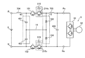
210、214、217 保護スイッチ(第11の保護スイッチ)
210a、213a、214a、217a 保護スイッチ(第12の保護スイッチ)
210c、213c、214c、217c 保護スイッチ(第13の保護スイッチ)
211、215、218 保護スイッチ(第14の保護スイッチ)
211a、212a、215a、218a 保護スイッチ(第15の保護スイッチ)
211c、212c、215c、218c 保護スイッチ(第16の保護スイッチ)
401 コンデンサ(第1のコンデンサ)
402 コンデンサ(第2のコンデンサ)
403 コンデンサ(第3のコンデンサ)
511 保護コンデンサ(第1の保護コンデンサ)
514 保護コンデンサ(第2の保護コンデンサ)
517 保護コンデンサ(第3の保護コンデンサ)
520 保護コンデンサ(第4の保護コンデンサ)
512、516、518、521 保護コンデンサ(第5の保護コンデンサ)
513、515、519、522 保護コンデンサ(第6の保護コンデンサ)
611 抵抗(第1の抵抗)
614 抵抗(第2の抵抗)
617 抵抗(第3の抵抗)
620 抵抗(第4の抵抗)
612、616、618、621 抵抗(第5の抵抗)
613、615、619、622 抵抗(第6の抵抗)
704 リアクトル(第1のリアクトル)
703 リアクトル(第2のリアクトル)
Claims (25)
- 直流電源と、
第1のスイッチおよび第2のスイッチと、
第1のダイオードおよび第2のダイオードと、
第1のコンデンサ、第2のコンデンサおよび第3のコンデンサと、
第1のリアクトルおよび第2のリアクトルと、
接続経路と、
保護スイッチ回路とを備え、
前記第1のスイッチと、前記第1のダイオードと、前記第2のダイオードと、前記第2のスイッチと、前記第2のコンデンサと、前記第1のコンデンサとは、この順で一巡に直列に接続され、
前記直流電源は、前記第1のリアクトルを介して、前記第1のコンデンサおよび前記第1のスイッチの接続点と、前記第2のスイッチおよび前記第2のコンデンサの接続点と、の間に並列に接続され、
前記第3のコンデンサは、前記第2のリアクトルを介して、前記第1のダイオードおよび前記第1のスイッチの接続点と、前記第2のスイッチおよび前記第2のダイオードの接続点と、の間に並列に接続され、
前記接続経路は、前記第1のダイオードおよび前記第2のダイオードの接続点と、前記第1のコンデンサおよび前記第2のコンデンサの接続点とを接続し、
前記保護スイッチ回路は、前記第1のスイッチおよび前記第1のダイオードのうちの少なくとも一方、または、前記第2のスイッチおよび前記第2のダイオードのうちの少なくとも一方の故障時に、前記第2のコンデンサ、または、前記第1のコンデンサに過電圧が印加される電流経路を、過電圧とならない電流経路へと変更するように制御可能に構成されている、3レベルチョッパ装置。 - 前記保護スイッチ回路は、前記接続経路に直列に接続されている双方向保護スイッチである、請求項1に記載の3レベルチョッパ装置。
- 前記双方向保護スイッチは、IGBT、MOSFETおよびバイポーラトランジスタのうちの少なくとも1つを含む半導体スイッチ素子とダイオードとを直列接続したスイッチ回路、または、逆阻止型IGBTが2個逆並列接続されることにより構成されている、請求項2に記載の3レベルチョッパ装置。
- 前記双方向保護スイッチは、IGBT、MOSFETおよびバイポーラトランジスタのうちの少なくとも1つを含む半導体スイッチ素子とダイオードとを逆並列接続したスイッチ回路、または、MOSFET、または、逆導通型IGBTが2個逆直列接続されて構成されている、請求項2に記載の3レベルチョッパ装置。
- 前記双方向保護スイッチを構成するダイオードは、シリコンダイオードを含む、請求項3または4に記載の3レベルチョッパ装置。
- 前記双方向保護スイッチを構成するダイオードは、炭化珪素ダイオードを含む、請求項3または4に記載の3レベルチョッパ装置。
- 前記双方向保護スイッチを構成するダイオードは、シリコンダイオードと炭化珪素ダイオードとを並列接続したダイオードを含む、請求項3または4に記載の3レベルチョッパ装置。
- 前記保護スイッチ回路は、前記双方向保護スイッチに並列に接続された第1の抵抗をさらに含む、請求項2〜7のいずれか1項に記載の3レベルチョッパ装置。
- 前記保護スイッチ回路は、前記双方向保護スイッチに並列に接続された第1の保護コンデンサをさらに含む、請求項2〜8のいずれか1項に記載の3レベルチョッパ装置。
- 前記保護スイッチ回路は、
前記第1のダイオードと前記接続経路の間に直列に接続される第1の保護スイッチと、
前記第2のダイオードと前記接続経路の間に直列に接続される第2の保護スイッチと、
前記第1のダイオードと前記第1の保護スイッチの接続点と、前記第2の保護スイッチと前記第2のダイオードの接続点との間に、並列に接続される第2の抵抗とを含む、請求項1に記載の3レベルチョッパ装置。 - 前記保護スイッチ回路は、
前記第1のダイオードと前記接続経路の間に直列に接続される第3の保護スイッチと、
前記第2のダイオードと前記接続経路の間に直列に接続される第4の保護スイッチと、
前記第1のダイオードと前記第3の保護スイッチの接続点と、前記第4の保護スイッチと前記第2のダイオードの接続点との間に、並列に接続される第2の保護コンデンサとを含む、請求項1に記載の3レベルチョッパ装置。 - 前記保護スイッチ回路は、
前記第1のコンデンサと前記接続経路の間に直列に接続される第5の保護スイッチと、
前記第2のコンデンサと前記接続経路の間に直列に接続される第6の保護スイッチと、
前記第1のコンデンサと前記第5の保護スイッチの接続点と、前記第6の保護スイッチと前記第2のコンデンサの接続点との間に、並列に接続される第3の抵抗とを含む、請求項1に記載の3レベルチョッパ装置。 - 前記保護スイッチ回路は、
前記第1のコンデンサと前記接続経路の間に直列に接続される第7の保護スイッチと、
前記第2のコンデンサと前記接続経路の間に直列に接続される第8の保護スイッチと、
前記第1のコンデンサと前記第7の保護スイッチの接続点と、前記第8の保護スイッチと前記第2のコンデンサの接続点との間に、並列に接続される第3の保護コンデンサとを含む、請求項1に記載の3レベルチョッパ装置。 - 前記保護スイッチ回路は、
前記第1のリアクトルに直列に接続される第9の保護スイッチと、
前記第9の保護スイッチの両端に並列に接続される第4の抵抗とを含む、請求項1に記載の3レベルチョッパ装置。 - 前記保護スイッチ回路は、
前記第1のリアクトルに直列に接続される第10の保護スイッチと、
前記第10の保護スイッチの両端に並列に接続される第4の保護コンデンサとを含む、請求項1に記載の3レベルチョッパ装置。 - 前記第3の抵抗、または、前記第4の抵抗の抵抗値をRとし、前記第1のリアクトルのインダクタンスをLとし、前記第1のコンデンサおよび前記第2のコンデンサのうちの容量の小さい方の容量をCとしたとき、抵抗値Rは、下記の式(1)を満たす、請求項12または14に記載の3レベルチョッパ装置。
R≧2×(2×L/C)1/2 ・・・(1) - 前記保護スイッチ回路は、
前記第1のスイッチまたは前記第2のコンデンサまたは前記第1のダイオードまたは前記接続経路に直列に接続されている第1の保護スイッチ部分回路と、
前記第2のスイッチまたは前記第1のコンデンサまたは前記第2のダイオードまたは前記接続経路に直列に接続されている第2の保護スイッチ部分回路との両方、または、いずれか一つを含む、請求項1に記載の3レベルチョッパ装置。 - 前記第1の保護スイッチ部分回路は、第11の保護スイッチを含み、前記第1のスイッチ、または、前記第1のダイオード、または、前記接続経路に直列に接続されている、請求項17に記載の3レベルチョッパ装置。
- 前記第1の保護スイッチ部分回路は、第12の保護スイッチと、前記第12の保護スイッチに並列接続された第5の抵抗とを含む、請求項17に記載の3レベルチョッパ装置。
- 前記第1の保護スイッチ部分回路は、前記第2のコンデンサに直列に接続されており、前記第5の抵抗の抵抗値をRaとし、前記第1のリアクトルのインダクタンスをLとし、前記第2のコンデンサの容量をC2としたとき、前記第5の抵抗の抵抗値Raは、下記の式(2)を満たす、請求項19に記載の3レベルチョッパ装置。
Ra≧2×(2×L/C2)1/2 ・・・(2) - 前記第1の保護スイッチ部分回路は、
第13の保護スイッチと、前記第13の保護スイッチに並列接続された第5の保護コンデンサを含む、請求項17に記載の3レベルチョッパ装置。 - 前記第2の保護スイッチ部分回路は、第14の保護スイッチを含み、前記第2のスイッチ、または、前記第2のダイオード、または、前記接続経路に直列に接続されている、請求項17〜21のいずれか1項に記載の3レベルチョッパ装置。
- 前記第2の保護スイッチ部分回路は、
第15の保護スイッチと、前記第15の保護スイッチに並列接続された第6の抵抗とを含む、請求項17〜21のいずれか1項に記載の3レベルチョッパ装置。 - 前記第2の保護スイッチ部分回路は、前記第1のコンデンサに直列に接続されており、
前記第6の抵抗の抵抗値をRbとし、前記第1のリアクトルのインダクタンスをLとし、前記第1のコンデンサの容量をC1としたとき、前記第6の抵抗の抵抗値Rbは、下記の式(3)を満たす、請求項23に記載の3レベルチョッパ装置。
Rb≧2×(2×L/C1)1/2 ・・・(3) - 前記第2の保護スイッチ部分回路は、
第16の保護スイッチと、前記第16の保護スイッチに並列接続された第6の保護コンデンサとを含む、請求項17〜21のいずれか1項に記載の3レベルチョッパ装置。
Priority Applications (2)
| Application Number | Priority Date | Filing Date | Title |
|---|---|---|---|
| JP2016080699A JP6662163B2 (ja) | 2016-04-14 | 2016-04-14 | 3レベルチョッパ装置 |
| US15/468,450 US10418801B2 (en) | 2016-04-14 | 2017-03-24 | Three-level chopper apparatus |
Applications Claiming Priority (1)
| Application Number | Priority Date | Filing Date | Title |
|---|---|---|---|
| JP2016080699A JP6662163B2 (ja) | 2016-04-14 | 2016-04-14 | 3レベルチョッパ装置 |
Publications (2)
| Publication Number | Publication Date |
|---|---|
| JP2017192219A true JP2017192219A (ja) | 2017-10-19 |
| JP6662163B2 JP6662163B2 (ja) | 2020-03-11 |
Family
ID=60038465
Family Applications (1)
| Application Number | Title | Priority Date | Filing Date |
|---|---|---|---|
| JP2016080699A Active JP6662163B2 (ja) | 2016-04-14 | 2016-04-14 | 3レベルチョッパ装置 |
Country Status (2)
| Country | Link |
|---|---|
| US (1) | US10418801B2 (ja) |
| JP (1) | JP6662163B2 (ja) |
Cited By (2)
| Publication number | Priority date | Publication date | Assignee | Title |
|---|---|---|---|---|
| JP2019092284A (ja) * | 2017-11-14 | 2019-06-13 | 富士電機株式会社 | 降圧チョッパ回路 |
| JP2022067826A (ja) * | 2020-10-21 | 2022-05-09 | コーセル株式会社 | 電源装置 |
Families Citing this family (8)
| Publication number | Priority date | Publication date | Assignee | Title |
|---|---|---|---|---|
| JP6731673B2 (ja) * | 2015-09-02 | 2020-07-29 | 国立大学法人東京工業大学 | 双方向チョッパ回路 |
| CN110350812B (zh) * | 2018-04-08 | 2024-08-13 | 佛山科学技术学院 | 一种用于ups的逆变器模块 |
| DE102018212825A1 (de) * | 2018-08-01 | 2020-02-06 | Schmidhauser Ag | DC/DC-Wandler und Netzrückspeiseeinheit |
| CN112542949A (zh) * | 2019-09-23 | 2021-03-23 | 中车株洲电力机车研究所有限公司 | Dc-dc电路的控制方法及装置 |
| EP3799306A1 (de) | 2019-09-27 | 2021-03-31 | Siemens Aktiengesellschaft | Elektronischer schutzschalter |
| US11469684B2 (en) * | 2020-06-11 | 2022-10-11 | Abb Schweiz Ag | Active damping of soft switching resonant converters |
| CN112600423A (zh) * | 2021-03-02 | 2021-04-02 | 四川华泰电气股份有限公司 | 三电平电池充放电变换器的电容平衡控制系统及方法 |
| EP4142144B1 (en) * | 2021-08-23 | 2025-06-18 | ABB Schweiz AG | Three-level brake chopper and method for controlling three-level brake chopper |
Citations (9)
| Publication number | Priority date | Publication date | Assignee | Title |
|---|---|---|---|---|
| JPH0274149A (ja) * | 1988-09-09 | 1990-03-14 | Mitsubishi Electric Corp | チョッパ装置 |
| JP2003143863A (ja) * | 2001-11-02 | 2003-05-16 | Mitsubishi Electric Corp | 電力変換装置 |
| WO2006003936A1 (ja) * | 2004-07-01 | 2006-01-12 | The Kansai Electric Power Co., Inc. | スナバ回路及びスナバ回路を有するパワー半導体装置 |
| JP2008153748A (ja) * | 2006-12-14 | 2008-07-03 | Matsushita Electric Ind Co Ltd | 双方向スイッチ及び双方向スイッチの駆動方法 |
| JP2013009467A (ja) * | 2011-06-22 | 2013-01-10 | Toshiba Corp | 蓄電装置 |
| WO2014146776A1 (en) * | 2013-03-22 | 2014-09-25 | Abb Ag | Switchgear assembly, dc power distribution system, dc power distribution board |
| JP2015065040A (ja) * | 2013-09-25 | 2015-04-09 | 東芝ライテック株式会社 | 電源装置及び照明装置 |
| WO2015079504A1 (ja) * | 2013-11-26 | 2015-06-04 | 三菱電機株式会社 | 直流電源装置、およびそれを備えた冷凍サイクル適用機器 |
| WO2015098651A1 (ja) * | 2013-12-25 | 2015-07-02 | 株式会社明電舎 | ゼロ電流スイッチング電力変換装置 |
Family Cites Families (7)
| Publication number | Priority date | Publication date | Assignee | Title |
|---|---|---|---|---|
| US6995987B2 (en) * | 2001-12-28 | 2006-02-07 | Northeastern University | DC—DC converters providing reduced deadtime |
| JP4308035B2 (ja) | 2004-02-06 | 2009-08-05 | 本田技研工業株式会社 | Dc/dcコンバータ、及びプログラム。 |
| EP1562279A3 (en) | 2004-02-06 | 2005-11-02 | HONDA MOTOR CO., Ltd. | DC/DC converter and program |
| JP4886562B2 (ja) | 2007-03-19 | 2012-02-29 | 本田技研工業株式会社 | 電力変換器及び多入出力電力変換器 |
| JP5070937B2 (ja) | 2007-05-25 | 2012-11-14 | 東芝三菱電機産業システム株式会社 | 昇圧チョッパ回路、降圧チョッパ回路及びそれを用いたdc−dcコンバータ回路 |
| JP5413420B2 (ja) | 2011-08-08 | 2014-02-12 | 株式会社デンソー | 回転機の制御装置 |
| JP6086157B2 (ja) * | 2013-10-02 | 2017-03-01 | 富士電機株式会社 | 3レベルインバータ |
-
2016
- 2016-04-14 JP JP2016080699A patent/JP6662163B2/ja active Active
-
2017
- 2017-03-24 US US15/468,450 patent/US10418801B2/en active Active
Patent Citations (9)
| Publication number | Priority date | Publication date | Assignee | Title |
|---|---|---|---|---|
| JPH0274149A (ja) * | 1988-09-09 | 1990-03-14 | Mitsubishi Electric Corp | チョッパ装置 |
| JP2003143863A (ja) * | 2001-11-02 | 2003-05-16 | Mitsubishi Electric Corp | 電力変換装置 |
| WO2006003936A1 (ja) * | 2004-07-01 | 2006-01-12 | The Kansai Electric Power Co., Inc. | スナバ回路及びスナバ回路を有するパワー半導体装置 |
| JP2008153748A (ja) * | 2006-12-14 | 2008-07-03 | Matsushita Electric Ind Co Ltd | 双方向スイッチ及び双方向スイッチの駆動方法 |
| JP2013009467A (ja) * | 2011-06-22 | 2013-01-10 | Toshiba Corp | 蓄電装置 |
| WO2014146776A1 (en) * | 2013-03-22 | 2014-09-25 | Abb Ag | Switchgear assembly, dc power distribution system, dc power distribution board |
| JP2015065040A (ja) * | 2013-09-25 | 2015-04-09 | 東芝ライテック株式会社 | 電源装置及び照明装置 |
| WO2015079504A1 (ja) * | 2013-11-26 | 2015-06-04 | 三菱電機株式会社 | 直流電源装置、およびそれを備えた冷凍サイクル適用機器 |
| WO2015098651A1 (ja) * | 2013-12-25 | 2015-07-02 | 株式会社明電舎 | ゼロ電流スイッチング電力変換装置 |
Cited By (4)
| Publication number | Priority date | Publication date | Assignee | Title |
|---|---|---|---|---|
| JP2019092284A (ja) * | 2017-11-14 | 2019-06-13 | 富士電機株式会社 | 降圧チョッパ回路 |
| JP7000809B2 (ja) | 2017-11-14 | 2022-01-19 | 富士電機株式会社 | 降圧チョッパ回路 |
| JP2022067826A (ja) * | 2020-10-21 | 2022-05-09 | コーセル株式会社 | 電源装置 |
| JP7319954B2 (ja) | 2020-10-21 | 2023-08-02 | コーセル株式会社 | 電源装置 |
Also Published As
| Publication number | Publication date |
|---|---|
| US10418801B2 (en) | 2019-09-17 |
| JP6662163B2 (ja) | 2020-03-11 |
| US20170302068A1 (en) | 2017-10-19 |
Similar Documents
| Publication | Publication Date | Title |
|---|---|---|
| JP6662163B2 (ja) | 3レベルチョッパ装置 | |
| US11139808B2 (en) | Semiconductor device and power conversion system | |
| US10148083B2 (en) | Fault current-suppressing damper topology circuit and control method thereof and converter | |
| US6496343B2 (en) | Overvoltage protection apparatus for a matrix converter | |
| JP5528946B2 (ja) | インダイレクトマトリクスコンバータ | |
| JP6798179B2 (ja) | 3レベルチョッパ装置 | |
| US8716986B2 (en) | Power conversion circuit | |
| JPH07297358A (ja) | 半導体パワーモジュールおよび電力変換装置 | |
| JP2009506736A (ja) | 分散配置されたエネルギー蓄積器を有する電力変換回路 | |
| CN109889028B (zh) | 一种吸收电容预充电电路和尖峰电压吸收电路 | |
| JP5257110B2 (ja) | 半導体試験装置 | |
| Piazzesi et al. | Series connection of 3.3 kV IGBTs with active voltage balancing | |
| WO2017022693A1 (ja) | 3レベルチョッパ装置 | |
| JP2019161725A (ja) | 電力変換装置及びインバータの制御方法 | |
| EP3574576B1 (en) | A protection arrangement for an mmc-hvdc sub-module | |
| JP6714834B2 (ja) | 3レベル電力変換回路 | |
| JP2004112916A (ja) | 電圧駆動型半導体素子のゲート駆動装置 | |
| US20210297073A1 (en) | Switching Device for Separating a Current Path | |
| JPH114150A (ja) | 半導体装置とこの半導体装置を用いた電力変換装置 | |
| JP3808326B2 (ja) | 電力変換装置 | |
| Kokkonda et al. | Performance comparison of 10 kV and series-connected 3.3 kV SiC MOSFETs based VSCs for MV grid interfacing applications | |
| JPH07250484A (ja) | 系統連系用高電圧自励変換装置 | |
| US5235487A (en) | Inverter with overload current protection | |
| JP3356783B2 (ja) | 電力変換装置及びモータ制御装置 | |
| WO2022243423A1 (en) | Electrical converter with overvoltage protection circuit |
Legal Events
| Date | Code | Title | Description |
|---|---|---|---|
| A621 | Written request for application examination |
Free format text: JAPANESE INTERMEDIATE CODE: A621 Effective date: 20190314 |
|
| A977 | Report on retrieval |
Free format text: JAPANESE INTERMEDIATE CODE: A971007 Effective date: 20191227 |
|
| TRDD | Decision of grant or rejection written | ||
| A01 | Written decision to grant a patent or to grant a registration (utility model) |
Free format text: JAPANESE INTERMEDIATE CODE: A01 Effective date: 20200114 |
|
| A61 | First payment of annual fees (during grant procedure) |
Free format text: JAPANESE INTERMEDIATE CODE: A61 Effective date: 20200127 |
|
| R150 | Certificate of patent or registration of utility model |
Ref document number: 6662163 Country of ref document: JP Free format text: JAPANESE INTERMEDIATE CODE: R150 |
|
| R250 | Receipt of annual fees |
Free format text: JAPANESE INTERMEDIATE CODE: R250 |
|
| R250 | Receipt of annual fees |
Free format text: JAPANESE INTERMEDIATE CODE: R250 |
|
| R250 | Receipt of annual fees |
Free format text: JAPANESE INTERMEDIATE CODE: R250 |
|
| R250 | Receipt of annual fees |
Free format text: JAPANESE INTERMEDIATE CODE: R250 |