JP2017192232A - Solar panel mount - Google Patents
Solar panel mount Download PDFInfo
- Publication number
- JP2017192232A JP2017192232A JP2016080936A JP2016080936A JP2017192232A JP 2017192232 A JP2017192232 A JP 2017192232A JP 2016080936 A JP2016080936 A JP 2016080936A JP 2016080936 A JP2016080936 A JP 2016080936A JP 2017192232 A JP2017192232 A JP 2017192232A
- Authority
- JP
- Japan
- Prior art keywords
- solar panel
- beam member
- support
- panel mount
- column
- Prior art date
- Legal status (The legal status is an assumption and is not a legal conclusion. Google has not performed a legal analysis and makes no representation as to the accuracy of the status listed.)
- Pending
Links
Images







Classifications
-
- Y—GENERAL TAGGING OF NEW TECHNOLOGICAL DEVELOPMENTS; GENERAL TAGGING OF CROSS-SECTIONAL TECHNOLOGIES SPANNING OVER SEVERAL SECTIONS OF THE IPC; TECHNICAL SUBJECTS COVERED BY FORMER USPC CROSS-REFERENCE ART COLLECTIONS [XRACs] AND DIGESTS
- Y02—TECHNOLOGIES OR APPLICATIONS FOR MITIGATION OR ADAPTATION AGAINST CLIMATE CHANGE
- Y02E—REDUCTION OF GREENHOUSE GAS [GHG] EMISSIONS, RELATED TO ENERGY GENERATION, TRANSMISSION OR DISTRIBUTION
- Y02E10/00—Energy generation through renewable energy sources
- Y02E10/50—Photovoltaic [PV] energy
Landscapes
- Photovoltaic Devices (AREA)
Abstract
【課題】 簡易な構成により太陽光パネルの傾斜方向及び傾斜角度の調整の自由度を高め、例えば、自然のままの斜面若しくはそれに近い人工的な斜面に対しても容易に対応することができる太陽光パネル用架台を提供すること。【解決手段】 支柱と、上記支柱に回動可能に設置された第1梁材と、上記第1梁材に設置され上記第1梁材の回動中心軸に直交する回動中心軸の周りに回動可能であって太陽光パネルが設置される第2梁材と、を具備したことを特徴とするもの。【選択図】 図2PROBLEM TO BE SOLVED: To increase the degree of freedom in adjusting a tilt direction and a tilt angle of a solar panel with a simple structure, and to easily cope with a natural slope or an artificial slope close to it. Providing a mount for optical panels. A support, a first beam member rotatably installed on the support, and a rotation center axis installed on the first beam member and orthogonal to a rotation center axis of the first beam member. A second beam member which is rotatable and on which a solar panel is installed. [Selection diagram]
Description
本発明は、太陽光パネルが設置される太陽光パネル用架台に係り、特に、簡易な構成により太陽光パネルの傾斜方向及び傾斜角度の調整の自由度を高め、例えば、自然のままの斜面若しくはそれに近い人工的な斜面に対しても容易に対応することができるように工夫したものに関する。 The present invention relates to a solar panel mount on which a solar panel is installed, and in particular, increases the degree of freedom in adjusting the inclination direction and inclination angle of the solar panel with a simple configuration, for example, a natural slope or The present invention relates to a device designed so that it can easily cope with an artificial slope close to it.
従来の太陽光パネル用架台の構成を開示するものとして、例えば、特許文献1がある。
この特許文献1に記載された太陽光パネル架台は、地面に打ち込まれた支柱と、この支柱の上端側に設置された角度調節機構と、この角度調節機構によって角度調節可能に支持されるとともに太陽光パネルが設置されるパネル受けとから構成されている。
For example, Patent Document 1 discloses a configuration of a conventional solar panel mount.
The solar panel pedestal described in Patent Document 1 is a column that is driven into the ground, an angle adjustment mechanism that is installed on the upper end side of the column, and is supported by the angle adjustment mechanism so that the angle can be adjusted and the sun. It consists of a panel receiver on which an optical panel is installed.
上記角度調節機構は、上記支柱に固着され上記パネル受けを回動可能に支持するブラケットと、その一端が上記パネル受けに回動可能に支持されその他端が上記ブラケットに回動可能であってスライド可能に支持された4本のリンク部材とから構成されている。また、上記ブラケットには長孔が形成されており、この長穴に上記リンク部材の回動軸を貫通させることにより、上記リンク部材の他端側が上記ブラケットに対して回動可能であってスライド可能に支持されるようになっている。
そして、上記4本のリンク部材の他端側の上記ブラケットの長穴内での固定位置を変えることにより上記パネル受けの角度を調整するように構成されている。
The angle adjusting mechanism includes a bracket that is fixed to the support column and rotatably supports the panel receiver, and one end of which is rotatably supported by the panel receiver and the other end of which is rotatable to the bracket and slides. It is comprised from the four link members supported so that it was possible. Further, the bracket is formed with a long hole, and the other end side of the link member is rotatable with respect to the bracket by allowing the rotation shaft of the link member to pass through the long hole. It comes to be supported as possible.
And it is comprised so that the angle of the said panel receiver may be adjusted by changing the fixing position in the long hole of the said bracket on the other end side of the said four link members.
しかし、上記従来の構成によると次のような問題があった。
すなわち、上記特許文献1に記載された太陽光パネル架台では、上記太陽光パネルを1つの回動軸を中心に回動させるだけであるので、太陽光パネルの傾斜方向及び傾斜角度の調整の自由度が低いという問題があった。
特に、自然のままの斜面若しくはそれに近い人工的な斜面に設置する場合には広範囲な調整が必要となり、従来の構成では限界があった。
なお、自然のままの傾斜面とは、例えば、山の傾斜面を伐採しただけの傾斜面であって切り株等がそのまま残っている斜面を意味するとともに、それに近い人工的な斜面とは、例えば、ゴルフ場における斜面のようなものを意味する。
However, the conventional configuration has the following problems.
That is, in the solar panel mount described in the above-mentioned Patent Document 1, the solar panel only needs to be rotated around one rotational axis, and therefore the solar panel tilt direction and tilt angle can be freely adjusted. There was a problem that the degree was low.
In particular, when it is installed on a natural slope or an artificial slope close thereto, a wide range of adjustment is necessary, and there is a limit in the conventional configuration.
In addition, the natural slope means, for example, a slope obtained by cutting a slope of a mountain and a stump or the like remains as it is, and an artificial slope close to it is, for example, It means something like a slope in a golf course.
本発明はこのような点に基づいてなされたものでその目的とするところは、簡易な構成により太陽光パネルの傾斜方向及び傾斜角度の調整の自由度を高め、例えば、自然のままの斜面若しくはそれに近い人工的な斜面に対しても容易に対応することができる太陽光パネル用架台を提供することにある。 The present invention has been made based on such points, and the object thereof is to increase the degree of freedom in adjusting the inclination direction and inclination angle of the solar panel with a simple configuration, for example, a natural slope or An object of the present invention is to provide a solar panel mount that can easily cope with an artificial slope close to it.
上記課題を解決するべく本願発明の請求項1による太陽光パネル用架台は、支柱と、上記支柱に回動可能に設置された第1梁材と、上記第1梁材に設置され上記第1梁材の回動中心軸に直交する回動中心軸の周りに回動可能であって太陽光パネルが設置される第2梁材と、を具備したことを特徴とするものである。
又、請求項2による太陽光パネル用架台は、請求項1記載の太陽光パネル用架台において、上記第1梁材は上記支柱に対して第1梁材の長手方向に移動可能に設置されていることを特徴とするものである。
又、請求項3による太陽光パネル用架台は、請求項1又は請求項2記載の太陽光パネル用架台において、上記第2梁材は上記第1梁材に対して第2梁材の長手方向に移動可能に設置されていることを特徴とするものである。
又、請求項4による太陽光パネル用架台は、請求項1〜請求項3の何れかに記載の太陽光パネル用架台において、上記支柱と上記第1梁材との間には上記第1梁材を支持するとともに上記第1梁材の上記支柱に対する回動を許容する第1リンク機構が設置されていることを特徴とするものである。
又、請求項5による太陽光パネル用架台は、請求項1〜請求項3の何れかに記載の太陽光パネル用架台において、上記支柱と上記第2梁材との間には上記第2梁材を支持するとともに上記第2梁材の上記第1梁材に対する回動を許容する第2リンク機構が設置されていることを特徴とするものである。
又、請求項6による太陽光パネル用架台は、請求項4記載の太陽光パネル用架台において、上記第1リンク機構は第1リンク部材を備えていて、この第1リング部材は、その一端が上記支柱と上記第1梁材の何れか一方に回動可能に連結されており、その他端が上記支柱と上記第1梁材の何れか他方に移動可能に連結されていることを特徴とするものである。
又、請求項7による太陽光パネル用架台は、請求項6記載の太陽光パネル用架台において、上記第1梁材の下面にはナットが内装される溝が延長・形成されており、上記第1リンク部材の他端は上記ナットにボルトを螺合させることにより連結されていて、上記ボルト・ナットの締結を緩めることにより上記第1リンク部材の他端が上記第1梁材に対して移動可能になることを特徴とするものである。
又、請求項8による太陽光パネル用架台は、請求項1〜請求項7の何れかに記載の太陽光パネル用架台において、上記第1梁材には上記第2梁材をその回動軸に直交する方向の少なくとも2箇所で支持する第2梁材用支持部が設置されており、上記第2梁材用支持部それぞれにおける上記第2梁材の支持位置を変えることによって上記第2梁材の傾斜角度を調整することを特徴とするものである。
又、請求項9による太陽光パネル用架台は、請求項8記載の太陽光パネル用架台において、上記第2梁材用支持部は上記第1梁材に固着され固定用係合部が設けられた係合部材と、上記係合部材の上記固定用係合部の任意の位置に係合される固定用被係合部を備えた被係合部材と、この被係合部材と上記係合部材と上記第2梁材を締結・固定する締結具とから構成されていることを特徴とするものである。
又、請求項10による太陽光パネル用架台は、請求項1〜請求項9の何れかに記載の太陽光パネル用架台において、上記支柱は中央に1本設けられていることを特徴とするものである。
又、請求項11による太陽光パネル用架台は、請求項1〜請求項9の何れかに記載の太陽光パネル用架台において、上記支柱は2本が離間配置されており、上記2本の支柱のそれぞれに上記第1梁材が設置されていて、上記2つの第1梁材に上記第2梁材が架け渡されていることを特徴とするものである。
In order to solve the above-mentioned problem, a solar panel mount according to claim 1 of the present invention is a column, a first beam member rotatably installed on the column, and a first beam member installed on the first beam member. And a second beam member that can be rotated around a rotation center axis orthogonal to the rotation center axis of the beam member and on which a solar panel is installed.
The solar panel mount according to claim 2 is the solar panel mount according to claim 1, wherein the first beam member is installed to be movable in the longitudinal direction of the first beam member with respect to the support column. It is characterized by being.
The solar panel mount according to
A solar panel gantry according to claim 4 is the solar panel gantry according to any one of claims 1 to 3, wherein the first beam is between the support column and the first beam member. A first link mechanism that supports the material and allows the first beam material to rotate with respect to the support column is provided.
A solar panel gantry according to
A solar panel mount according to
According to a seventh aspect of the present invention, there is provided the solar panel mount according to the sixth aspect, wherein a groove in which a nut is internally provided is formed on the lower surface of the first beam member. The other end of one link member is connected by screwing a bolt into the nut, and the other end of the first link member moves relative to the first beam member by loosening the fastening of the bolt and nut. It is characterized by being possible.
Further, a solar panel mount according to
The solar panel mount according to
A solar panel gantry according to claim 10 is the solar panel gantry according to any one of claims 1 to 9, characterized in that one support column is provided in the center. It is.
A solar panel gantry according to
以上述べたように、本願発明の請求項1記載の太陽光パネル用架台によると、支柱と、上記支柱に回動可能に設置された第1梁材と、上記第1梁材に設置され上記第1梁材の回動中心軸に直交する回動中心軸の周りに回動可能であって太陽光パネルが設置される第2梁材と、を具備したため、簡易な構成により、太陽光パネルの傾斜方向及び傾斜角度の調整の自由度を高め、それによって、例えば、自然のままの斜面若しくはそれに近い人工的な斜面に対しても容易に対応することができる。
又、請求項2記載の太陽光パネル用架台によると、請求項1記載の太陽光パネル用架台において、上記第1梁材は上記支柱に対して第1梁材の長手方向に移動可能に設置されているので、支柱に対する太陽光パネルの位置を調整することができ、様々な立地条件に対応することができる。
又、請求項3記載の太陽光パネル用架台によると、請求項1又は請求項2記載の太陽光パネル用架台において、上記第2梁材は上記第1梁材に対して第2梁材の長手方向に移動可能に設置されているので、上記効果をさらに高めることができる。
又、請求項4による太陽光パネル用架台は、請求項1〜請求項3の何れかに記載の太陽光パネル用架台において、上記支柱と上記第1梁材との間には上記第1梁材を支持するとともに上記第1梁材の上記支柱に対する回動を許容する第1リンク機構が設置されているため、上記第1梁材を確実に支持することができる。
又、請求項5による太陽光パネル用架台は、請求項1〜請求項3の何れかに記載の太陽光パネル用架台において、上記支柱と上記第2梁材との間には上記第2梁材を支持するとともに上記第2梁材の上記第1梁材に対する回動を許容する第2リンク機構が設置されているため、上記第2梁材を確実に支持することができる。
又、請求項6による太陽光パネル用架台は、請求項4記載の太陽光パネル用架台において、上記第1リンク機構は第1リンク部材を備えていて、この第1リング部材は、その一端が上記支柱と上記第1梁材の何れか一方に回動可能に連結されており、その他端が上記支柱と上記第1梁材の何れか他方に移動可能に連結されているため、簡易な構成により、上記第1梁材を確実に支持するとともに傾斜方向及び傾斜角度を調整可能とすることができる。
又、請求項7記載の太陽光パネル用架台によると、請求項6記載の太陽光パネル用架台において、上記第1梁材の下面にはナットが内装される溝が延長・形成されており、上記第1リンク部材の他端は上記ナットにボルトを螺合させることにより連結されていて、上記ボルト・ナットの締結を緩めることにより上記第1リンクの他端が上記第1梁材に対して移動可能になるため、簡易な構成により上記第1梁材を確実に支持するとともに傾斜方向及び傾斜角度を調整可能とすることができる。
又、請求項8記載の太陽光パネル用架台によると、請求項1〜請求項7の何れかに記載の太陽光パネル用架台において、上記第1梁材には上記第2梁材をその回動軸に直交する方向の少なくとも2箇所で支持する第2梁材用支持部が設置されており、上記第2梁材用支持部それぞれにおける上記第2梁材の支持位置を変えることによって上記第2梁材の傾斜角度を調整するため、簡易な構成による上記第2梁材の傾斜角度を調整することができる。
又、請求項9記載の太陽光パネル用架台によると、請求項8記載の太陽光パネル用架台において、上記第2梁材用支持部は上記第1梁材に固着され固定用係合部が設けられた係合部材と、上記係合部材の上記固定用係合部の任意の位置に係合される固定用被係合部を備えた被係合部材と、この被係合部材と上記係合部材と上記第2梁材を締結・固定する締結具とから構成されているため、上記第2梁材を確実に支持するとともに傾斜方向及び傾斜角度を調整可能とすることができる。
又、請求項10記載の太陽光パネル用架台によると、請求項1〜請求項9の何れかに記載の太陽光パネル用架台において、上記支柱は中央に1本設けられているため、簡易な構成により太陽光パネルを傾斜方向及び傾斜角度を調整可能に支持することができる。
又、請求項11記載の太陽光パネル用架台によると、請求項1〜請求項9の何れかに記載の太陽光パネル用架台において、上記支柱は2本が離間配置されており、上記2本の支柱のそれぞれに上記第1梁材が設置されていて、上記2つの第1梁材に上記第2梁材が架け渡されているため、より安定した状態で太陽光パネルを支持することができる。
As described above, according to the solar panel stand of the first aspect of the present invention, the support column, the first beam member rotatably installed on the support column, and the first beam member installed on the first beam member are described above. And a second beam member that can be rotated around a rotation center axis that is orthogonal to the rotation center axis of the first beam member and on which the solar panel is installed. The degree of freedom of adjustment of the inclination direction and the inclination angle is increased, so that it is possible to easily cope with, for example, a natural slope or an artificial slope close thereto.
Moreover, according to the solar panel mount according to claim 2, in the solar panel mount according to claim 1, the first beam member is installed to be movable in the longitudinal direction of the first beam member with respect to the support column. Therefore, it is possible to adjust the position of the solar panel with respect to the support column and to cope with various location conditions.
According to the solar panel gantry according to
A solar panel gantry according to claim 4 is the solar panel gantry according to any one of claims 1 to 3, wherein the first beam is between the support column and the first beam member. Since the 1st link mechanism which supports rotation with respect to the said support | pillar of the said 1st beam material while installing a material is installed, the said 1st beam material can be supported reliably.
A solar panel gantry according to
A solar panel mount according to
Further, according to the solar panel mount according to
Further, according to the solar panel gantry according to
Further, according to the solar panel mount according to
Moreover, according to the solar panel mount according to claim 10, in the solar panel mount according to any one of claims 1 to 9, since one of the support columns is provided in the center, it is simple. The solar panel can be supported by the configuration so that the inclination direction and the inclination angle can be adjusted.
Further, according to the solar panel mount according to
以下、図1乃至図8を参照して本発明の第1の実施の形態を説明する。
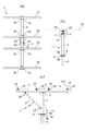
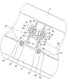
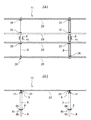
本実施の形態による太陽光パネル用架台1には、図1、図2に示すように、複数枚(この第1の実施の形態の場合は4枚)の太陽光パネル3が載置・固定されている。また、本実施の形態による太陽光パネル用架台1は、上記太陽光パネル3の傾斜角度を、図2(a)に示すように、左右方向に0°〜±30°の範囲で調整可能となっているとともに、図2(b)に示すように、前後方向にも0°〜±30°の範囲で調整可能となっている。
以下、上記太陽光パネル用架台1の構成を詳細に説明する。
Hereinafter, a first embodiment of the present invention will be described with reference to FIGS.
As shown in FIGS. 1 and 2, a plurality of solar panels 3 (four in the case of the first embodiment) are placed and fixed on the solar panel mount 1 according to the present embodiment. Has been. Moreover, the solar panel mount 1 according to the present embodiment can adjust the inclination angle of the
Hereinafter, the configuration of the solar panel mount 1 will be described in detail.
まず、支柱5があり、この支柱5は、中空の略四角柱形状の部材で、図4に示すように、その上端であって左右両側には、ナット7、7が、例えば、溶接によって固着されている。
First, there is a
また、図1に示すように、上記支柱5の下部には、設置用プレート6が、例えば、溶接によって固着されている。この設置用プレート6の下方には短管8が連結されていて、この短管8の上端にはフランジ8bが固着されている。そして、図5(b)に示すように、上記設置用プレート6と上記フランジ8bを当接させて、ボルト8a及びナット8cからなる複数組の締結具により締結・固定される。
なお、上記短管8はその一部が地中に埋設される或いは図示しないコンクリート製基礎に取付・固定されることになる。
As shown in FIG. 1, an
A part of the
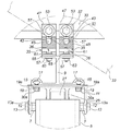
例えば、図4、図5(a)に示すように、上記支柱5の上端には、第1梁材9が第1梁材用支持部材11を介して回動可能に設置されている。この第1梁材用支持部材11は、略コの字型の端面形状を成すチャンネル材から構成されていて、その両側には、図4中左右方向に延長された貫通孔12、12が形成されている。上記支柱5と上記第1梁材用支持部材11は、ボルト13、13を上記貫通孔12、12を通して、上記支柱5に固着された上記ナット7、7に螺合させることにより固定されている。また、上記ボルト13、13の頭部と上記第1梁材用支持部材11との間には、それぞれワッシャ13a、13aが介挿されている。
For example, as shown in FIG. 4 and FIG. 5A, the
また、図4に示すように、上記第1梁材9の端面形状は略横H型をなしていて、図4中下端側の左右方向両側にT型溝15、15が形成されている。このような端面形状が図4中紙面垂直方向に連続している。上記T型溝15、15内には、T型ナット17、17が図4中左右に2個ずつ内装されている。上記第1梁材9は、左右2本ずつのボルト19、19を、上記第1梁材用支持部材11の図示しない貫通孔を通して上記左右2個ずつのT型ナット17、17に螺合させることにより固定されている。また、上記ボルト19、19の頭部と上記第1梁材用支持部材11との間には、それぞれワッシャ19a、19aが介挿されている。
As shown in FIG. 4, the end face shape of the
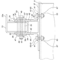
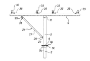
また、図3(c)に示すように、上記支柱5の下端側(図3(c)中下側)と上記第1梁材9の後端側(図3(c)中左側)はリンク機構21によって連結されている。このリンク機構21は、図5(b)に示すように、上記支柱5の下端側(図3(c)中下側)に固着されチャンネル材からなる支柱側支点用部材23と、上記第1梁材9の後端側(図3(c)中左側)に設置された第1梁材側支点用部材25と、その両端側を上記支柱側支点用部材23と上記第1梁材側支点用部材25に回動可能に連結されたリンク部材27とから構成される。
Further, as shown in FIG. 3C, the lower end side (lower side in FIG. 3C) of the
上記リンク部材27の下端側は、図5(b)に示すように、ボルト29を上記支柱側支点用部材23と上記リンク部材27を通して、図示しないナットに螺合させることにより固定されている。上記ボルト29の頭部と上記支柱側支点用部材23との間にはワッシャ29aが介挿されている。また、上記リンク部材27の上端側は、図5(c)、図5(d)に示すように、ボルト31を上記第1梁材側支点用部材25と上記リンク部材27を通して、ナット28に螺合させることにより固定されている。上記ボルト31の頭部と上記第1梁材側支点用部材25との間にはワッシャ31aが介挿されており、上記ナット28と上記第1梁材側支点用部材25との間にはワッシャ31bが介挿されている。
また、上記第1梁材側支点用部材25は、図5(d)に示すように、ボルト30aを上記第1梁材側支点用部材25を通して、上記第1梁材9のT型溝15、15内に内装されたT型ナット30b、30bに螺合させることにより固定されている。上記ボルト30aの頭部と上記第1梁材側支点用部材25との間にはワッシャ30cが介挿されている。
As shown in FIG. 5B, the lower end side of the
In addition, as shown in FIG. 5D, the first beam member
そして、上記ボルト13、13を緩めることによって上記第1梁材9が上記支柱5に対して回動可能な状態となり、上記ボルト29、31を緩めることによって上記リンク部材27が上記支柱側支点用部材23と上記第1梁材側支点用部材25に対して回動可能な状態となる。また、上記第1梁材側支点用部材25を固定しているボルト30a、30aを緩めることにより、上記第1梁材側支点用部材25が上記第1梁材9に沿って移動可能な状態となる。そのような状態で、上記第1梁材9の前後方向(図2(b)中左右方向)の傾斜を調整する。
また、上記ボルト19、19と上記ボルト30a、30aを緩めることにより、上記第1梁材用支持部材11に対して上記第1梁材9が移動可能な状態となり、上記第1梁材9に対する上記第1梁材用支持部材11の支持位置を調整できるようになっている。
Then, by loosening the
Further, by loosening the
また、例えば、図3(a)に示すように、複数本(この第1の実施の形態の場合には4本)の第2梁材33が、上記第1梁材9に対して直交する方向に延長された状態で回動可能に設置されている。これら第2梁材33は、中空の略四角柱形状の部材であり、これら複数本の第2梁材33上に既に説明した複数枚の太陽光パネル3が載置・固定されている。
なお、図8に示すように、上記第2梁材33には張出部33aが設けられている。上記第2梁材33は、図8に示す端面形状が紙面に垂直な方向に連続した形状になっている。
Further, for example, as shown in FIG. 3A, a plurality of (four in the case of the first embodiment)
As shown in FIG. 8, the
上記第1梁材9の所定の4箇所には、それぞれ2個の第2梁材用支持部35、35が、上記第2梁材33の長手方向に並んで設置されている。上記第2梁材用支持部35には、図8に示すように、まず、係合部材36がある。この係合部材36は、図6に示すように、基部37とこの基部37の中央に所定の間隔で立設された一対の支持部39、39とから構成されている。上記基部37には、固定用貫通長孔41、41が形成されている。また、上記支持部39には、第2梁材用貫通長孔43が形成されている。この第2梁材用貫通長孔43は、図6(c)中上下方向に延長・形成されている。また、上記支持部39の外側面(図6(b)中右側又は左側の面)には、ギザギザ状の固定用係合部45が形成されている。
Two second beam
また、図4に示すように、上記係合部材36の上記一対の支持部39、39には被係合部材47、47が係合されている。これら被係合部材47、47は、図7に示すように、板状の部材であり、貫通孔49が形成されている。また、上記被係合部材47の一方の面(図7(b)中右側の面)には、ギザギザ状の固定用被係合部51が形成されている。この固定用被係合部51と、上記係合部材36の支持部39の固定用係合部45が係合されることになる。
Further, as shown in FIG. 4, engaged
そして、図8に示すように、上記第2梁材33は、上記係合部材36の支持部39、39間に設置され、ボルト53を、一方の被係合部材47、上記係合部材36の一方の(図8中左側の)支持部39、上記第2梁材33に形成された貫通孔54、54、及び、上記係合部材36の他方の(図8中右側の)支持部39、他方の被係合部材47を通して、ナット55に螺合させることにより固定されている。また、上記ボルト53の頭部と図8中左側の被係合部材47との間にはワッシャ57が介挿されており、上記ナット55と図8中右側の被係合部材47との間にはワッシャ59が介挿されている。
また、上記支持部39、39間には、上記貫通孔54、54を通して、カラ56が介挿されていて、上記ボルト53と上記ナット55によって締結した際、上記第2梁材33が変形してしまうのを防止している。
As shown in FIG. 8, the
Further, a
また、図4に示すように、上記第2梁材33が水平状態にある場合には、上記第2梁材用支持部35、35のそれぞれの上記被係合部材47、47は同じ高さ位置にある。これに対して、図4中仮想線で示すように、例えば、上記第2梁材33の右側を下げて図4(a)中右下がりの傾斜に設定しようとすると、図中右側の被係合部材47が下に押し下げられることになる。このようにして、上記第2梁材33を左右方向に傾斜させるものである。
また、2つの上記第2梁材用支持部35、35によって上記第2梁材33を2箇所で支持することにより、上記第2梁材33の不用意な回動を規制することができる構成になっている。
As shown in FIG. 4, when the
In addition, the
また、上記係合部材36は、図4に示すように、ボルト61を上記係合部材36の固定用貫通長孔41と第1梁材9の図4中上側に形成された図示しない貫通孔を通して、ナット63に螺合させることにより固定されている。また、上記ボルト61の頭部と上記係合部材36との間にはワッシャ65が介挿されており、上記ナット63上記第1梁材9の図4中上側部分との間にはワッシャ67が介挿されている。
なお、既に述べたように、上記2つの第2梁材用支持部35、35は、第1梁材9の長手方向の所定の4箇所に設置されており、何れも同様の構成になっている。
Further, as shown in FIG. 4, the engaging
As described above, the two second beam
次に、この第1の実施の形態による作用について説明する。
前述したように、太陽光パネル用架台1には、図1、図2に示すように、複数枚(この第1の実施の形態の場合は4枚)の太陽光パネル3が載置・固定されている。そして、それら4枚の上記太陽光パネル3の傾斜角度は、図2(a)に示すように、左右方向に0°〜±30°の範囲で調整されるとともに、図2(b)に示すように、前後方向にも0°〜±30°の範囲で調整される。
Next, the operation of the first embodiment will be described.
As described above, a plurality of solar panels 3 (four in the case of the first embodiment) are placed and fixed on the solar panel mount 1 as shown in FIGS. Has been. And the inclination | tilt angle of these four said
左右方向の傾斜角度は、2つの第2梁材用支持部35、35において、ボルト53、53を緩め、上記被係合部材47、47の上記係合部材36の支持部39、39に対する係合位置を変えることにより調整される。
尚、4本の第2梁材33は全て同じ傾斜角度になるように調整される。
また、前後方向の傾斜角度は、第1梁材用支持部材11を固定しているボルト13、13、リンク機構21のボルト29、31、及び、上記リンク機構21の第1梁材側支点用部材25を固定しているボルト30aを緩めて、第1梁材9を回動させることにより調整される。
このように、上記太陽光パネル用架台1は、太陽光パネル3を2つの回動軸を中心に回動させて傾斜させるようになっている。
そして、本実施の形態による太陽光パネル用架台1は、例えば、切り株がそのまま放置された自然のままの斜面若しくはそれに近い人工的な斜面に複数台並んで設置される。その際、設置される場所の傾斜状況に応じて、各太陽光パネル用架台1毎に、既に説明した左右方向、前後方向の傾斜角度の調整が行われる。
また、必要であれば、第1梁材用支持部材11を通すボルト19、19と第1梁材側支点用部材25を通すボルト30a、30aを緩めることにより、上記第1梁材用支持部材11に対して上記第1梁材9を移動可能な状態とし、上記第1梁材9に対する上記第1梁材用支持部材11の支持位置の調整を行う。
The inclination angle in the left-right direction is such that the
The four
Further, the inclination angle in the front-rear direction is for the
As described above, the solar panel gantry 1 is configured such that the
Then, a plurality of solar panel mounts 1 according to the present embodiment are installed side by side on a natural slope where a stump is left as it is or an artificial slope close thereto. At that time, the adjustment of the inclination angles in the left-right direction and the front-rear direction described above is performed for each solar panel gantry 1 according to the inclination state of the place where it is installed.
If necessary, the
次に、この第1の実施の形態による効果について説明する。
まず、支柱5に対して、第1梁材9が前後方向に回動可能に設置されており、この第1梁材9に対して複数本の第2梁材33が左右方向に回動可能に設置されており、太陽光パネル3を2つの回動軸を中心に適宜回動させることができるので、太陽光パネル3の傾斜方向及び傾斜角度を広範囲で調整して、例えば、切り株がそのまま放置された自然のままの斜面若しくはそれに近い人工的な斜面に応じた最適な設置状態を得ることができ、それによって、発電効率の向上を図ることができる。
また、例えば、切り株がそのまま放置された自然のままの斜面若しくはそれに近い人工的な斜面に上記太陽光パネル用架台1を複数台並べて設置した場合においても、各太陽光パネル用架台1毎に傾斜方向及び傾斜角度を広範囲で調整することができるので、自然のままの傾斜面に対して効果的に対応することができる。
Next, the effect of the first embodiment will be described.
First, the
In addition, for example, even when a plurality of solar panel mounts 1 are installed side by side on a natural slope on which a stump is left as it is or an artificial slope close thereto, each solar panel mount 1 is inclined. Since the direction and the inclination angle can be adjusted over a wide range, it is possible to effectively cope with the natural inclined surface.
また、太陽光パネル3を2つの回動軸を中心に適宜回動させるための構成も簡単である。
また、第2梁材33を左右方向に回動させてその傾斜角度を調整して固定する場合には、上記被係合部材47の固定用被係合部51を上記係合部材36の支持部39の固定用係合部45に係合させる構成になっているので、強固な固定状態を得ることができる。
また、支柱5と第1梁材9との間にはリンク機構21が設置されているので、上記第1梁材9を確実に支持することができる。
また、必要であれば、ボルト19、19と上記リンク機構21のボルト30a、30aを緩めることにより、上記第1梁材用支持部材11に対して上記第1梁材9を移動可能な状態とし、上記第1梁材9に対する上記第1梁材用支持部材11の支持位置の調整を行うこともでき、それによって、太陽光パネル3と支柱5の上記第1梁材9の長手方向に沿った相対位置をずらすことができる。これは、太陽パネル3の位置をそのままとし、支柱5を、例えば、切り株のない場所に移動させたいような場合に好都合である。
Moreover, the structure for appropriately rotating the
Further, when the
Moreover, since the
If necessary, the
次に、図9乃至図14を参照して本発明の第2の実施の形態を説明する。
この第2の実施の形態による太陽光パネル用架台71は、前記第1の実施の形態による太陽光パネル用架台1と略同様の構成であるが、太陽光パネル3と支柱5との相対的位置関係をより広範囲に調整可能な構成になっている。
以下、詳細に説明する。
まず、前記第1の実施の形態による太陽光パネル用架台1では、第1梁材9が支柱5に対して移動可能に構成されていて、上記第1梁材9の上記支柱5に対する位置を調整できるようになっていた。この第2の実施の形態のよる太陽光パネル用架台71では、それに加えて、第2梁材73が上記第1梁材9に対して移動可能に構成されていて、上記第1梁材9に対する上記第2梁材73の位置を調整できるようになっている。
その結果、太陽光パネル3と支柱5との相対的位置をより広範囲に調整することができる。以下、詳しく説明する。
Next, a second embodiment of the present invention will be described with reference to FIGS.
The
Details will be described below.
First, in the solar panel gantry 1 according to the first embodiment, the
As a result, the relative position between the
図11に示すように、第2梁材73は、中空の略四角柱形状の部材であり、側面(図11中左右側の面)にはT型溝75、75が形成されているとともに、底面(図11中下側の面)にはT型溝77が形成されている。
なお、図11に示すように、上記第2梁材73には張出部79が設けられている。また、上記第2梁材73は、図11に示す端面形状が紙面に垂直な方向に連続した形状になっている。
As shown in FIG. 11, the
As shown in FIG. 11, the
上記T型溝75、75内にはT型ナット81、81が内装されていて、上記第2梁材73は、ボルト83、83を被係合部材47、係合部材36の支持部39、39を通して、上記T型ナット81、81に螺合させることにより、係合部材36に固定されている。また、上記ボルト83、83の頭部と上記被係合部材47との間には、ワッシャ84、84が介挿されている。
なお、図11では片側の第2梁材用支持部35が図示されているが、図11中奥側に別の第2梁材用支持部35が設置されている。
また、この第2の実施の形態の場合には、4本の第2梁材73が使用されており、何れの接合部も同様の構成になっている。
そして、全ての接合部において、各第2梁材用支持部35における上記ボルト83、83を緩めることにより、4本の第2梁材73を上記第1梁材9に対して移動させてその位置を調整することができる。
T-shaped
In FIG. 11, the second beam
In the case of the second embodiment, four
Then, in all the joints, by loosening the
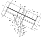
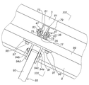
また、上記太陽光パネル用架台71には、リンク機構21とは別のリンク機構85が設けられている。このリンク機構85によって、上記4本の第2梁材73の一方の端部側(図10中紙面垂直方向手前側)を支持している。このリンク機構85は、図10に示すように、上記支柱5の下部(図10中下側)に回動可能に設置された支柱側支点用部材87と、上記第2梁材73側に設置された第2梁材端部支持部材89と、この第2梁材端部支持部材89に固着された第2梁材側支点用部材91と、その両端側を上記支柱側支点用部材87と上記第2梁材側支点用部材91に回動可能に連結されたリンク部材93とから構成されている。
The
また、上記リンク部材93の下端側は、図10に示すように、ボルト92aを上記支柱側支点用部材87と上記リンク部材93に通し、ナット92bに螺合させることで固定されている。また、上記リンク部材93の上端側は、図12に示すように、ボルト94aを上記第2梁材側支点用部材91と上記リンク部材93に通し、ナット94bに螺合させることで固定されている。また、上記ボルト94aの頭部と上記第2梁材側支点用部材91の間にはワッシャ94cが介挿されており、上記ナット94bの頭部と上記第2梁材側支点用部材91の間にはワッシャ94dが介挿されている。
よって、上記ボルト92aを緩めることで、上記リンク部材93が上記支柱側支点用部材87に対して回動可能になり、上記ボルト94aを緩めることで、上記リンク部材93が上記第2梁材側支点用部材91に対して回動可能になる。
上記支柱側支点用部材87は、図10(b)中左右二箇所において、図示しないボルト及びナットにより、上記支柱5に対して回転可能な状態で固定されている。そして、傾斜角度を調整する場合には、一方のボルト及びナットを外して残りのボルトを中心に回動可能な状態にして行う。そして、傾斜角度の調整が終わった後外したボルト及びナット締結する。
尚、上記着脱するボルト及びナット側の支柱5の部位には図示しない長孔が形成されている。
Further, as shown in FIG. 10, the lower end side of the
Therefore, by loosening the
The strut-
In addition, a long hole (not shown) is formed in the part of the
上記第2梁材端部支持部材89は、図13に示すように、四角柱の4つの側面に、それぞれT型溝95、95、95、95が形成されたものであり、図13に示す断面形状が紙面に垂直な方向に連続した形状になっている。
上記第2梁材側支点用部材91は、ボルト97を、上記第2梁材端部支持部材89の図13中下側のT型溝95に内装されたT型ナット99に螺合させることで、上記第2梁材端部支持部材89に固定されている。また、上記ボルト97の頭部と上記第2梁材側支点用部材91との間には、ワッシャ98が介挿されている。
よって、上記ボルト97を緩めることにより、上記第2梁材側支点用部材91を上記第2梁材端部支持部材89の長さ方向(図13中紙面垂直方向)に移動できるように構成されている。
As shown in FIG. 13, the second beam member
The second beam member
Therefore, by loosening the
また、上記第2梁材端部支持部材89は、図14に示すように、ボルト101を上記第2梁材73のT型溝77に内装されたT型ナット103に螺合させることにより、上記第2梁材73に固定されている。また、上記ボルト101の頭部と上記第2梁材端部支持部材89との間には、ワッシャ102が介挿されている。
そして、上記ボルト101を緩めることにより、上記第2梁材端部支持部材89を上記第2梁材73の長さ方向(図14中左右方向)に移動できるように構成されている。
なお、上記太陽光パネル用架台71に設置された上記第2梁材73の内、図10中左右両端の第2梁材73が上記第2梁材端部支持部材89に固定されており、残りの第2梁材73は、上記第2梁材端部支持部材89の上に載置された状態となっている。また、図14に示すように、上記第2梁材端部支持部材89の、上記第2梁材73を固定する部分には、ボルト用貫通孔104が形成されていて、このボルト用貫通孔104を介して、上記第2梁材端部支持部材89内に上記ボルト101やワッシャ102を挿入できるようになっている。
なお、この第2の実施の形態の場合には、図10に示すように、左右方向に0°〜±25°の範囲で調整可能となっているとともに、前後方向にも0°〜±25°の範囲で調整可能となっている。
Further, as shown in FIG. 14, the second beam member
The second beam member
Of the
In the case of the second embodiment, as shown in FIG. 10, the adjustment can be made in the range of 0 ° to ± 25 ° in the left-right direction and 0 ° to ± 25 in the front-rear direction. Adjustable in the range of °.
次に、この第2の実施の形態による作用について説明する。
まず、この第2の実施の形態による太陽光パネル用架台71も、前記第1の実施の形態による太陽光パネル用架台1と同様に、太陽光パネル3を前後方向、及び、左右方向に傾斜させることができる。
ただし、上記太陽光パネル用架台71には、リンク機構85が設置されているので、左右方向に傾斜させる場合、すなわち、第2梁材73を傾斜させる場合は、第2梁材用支持部35のボルト83、83だけでなく、上記リンク機構85のボルト92aとボルト94aと第2梁材端部支持部材89を通すボルト101も緩める必要がある。
Next, the operation of the second embodiment will be described.
First, the
However, since the
また、上記太陽光パネル用架台71は、前記第1の実施の形態による太陽光パネル用架台1と同様に、上記太陽光パネル3を前後方向に移動させることができる。
ただし、上記太陽光パネル用架台71には、リンク機構85が設置されているので、第1梁材用支持部材11を通すボルト19、19と第1梁材側支点用部材25を通すボルト30a、30aだけでなく、上記リンク機構85の第2梁材側支点用部材91を第2梁材端部支持部材89に固定するボルト97、97も緩める必要がある。
Moreover, the
However, since the
また、上記太陽光パネル用架台71は、上記太陽光パネル3を左右方向にも移動させることができる。このとき、第2梁材用支持部35のボルト83、83と、第2梁材端部支持部材89を通すボルト101を緩める必要がある。
The
この第2の実施の形態の場合は、前記第1の実施の形態の場合と同様の効果に加え、太陽光パネル3を左右方向にも移動させることができるという効果も奏するものである。
例えば、切り株がそのまま放置された自然のままの斜面若しくはそれに近い人工的な斜面に複数個の太陽光パネル用架台1を設置する場合、それぞれの太陽光パネル用架台1に取り付けられる太陽光パネル3の位置が決められている場合がある。通常であれば、太陽光パネル3の位置が決められれば、必然的に、太陽光パネル用架台1の位置ひいては支柱5の位置も決められることになる。ところが、切り株がそのまま放置された自然のままの傾斜面の場合には、その支柱5の位置に切り株が残されていることもあり、そのままでは設置できないということになる。
前記第1の実施の形態の場合には、第1梁材9を支柱5に対して移動させることによりそれに対処していたが、この第2の実施の形態の場合には、それに加えて、第2梁材73を第1梁材9に対して移動可能としており、それによって、太陽光パネル3と支柱5の相対位置を直交する二方向に調整できるので、太陽光パネル3の位置をそのままとして支柱5の位置をより広範囲にずらして残されている切り株を避けることができる。
このように、切り株がそのまま放置された自然のままの斜面若しくはそれに近い人工的な斜面に対しても、前記第1の実施の形態の場合以上に効果的に対応することができるものである。
また、支柱5と第2梁材73との間にもリンク機構85が設置されているので、上記第2梁材73を確実に支持することができる。
In the case of the second embodiment, in addition to the same effect as in the case of the first embodiment, there is also an effect that the
For example, when a plurality of solar panel mounts 1 are installed on a natural slope where a stump is left as it is or on an artificial slope close thereto, the
In the case of the first embodiment, it has been dealt with by moving the
Thus, it is possible to cope more effectively with the natural slope in which the stump is left as it is or an artificial slope close thereto than in the case of the first embodiment.
Moreover, since the
次に、図15乃至図18を参照して本発明の第3の実施の形態を説明する。
この第3の実施の形態による太陽光パネル用架台111は、前記第1の実施の形態による太陽光パネル用架台1と略同様の構成であるが、図15乃至図18に示すように、支柱5と第1梁材9がそれぞれ2本ずつ設置されている点と、第2梁材33の長さが前記第1の実施の形態による太陽光パネル用架台1の場合よりも長く設定されている点と、太陽光パネル3が12枚設置されている点、で異なっている。
Next, a third embodiment of the present invention will be described with reference to FIGS.
The solar panel mount 111 according to the third embodiment has substantially the same configuration as the solar panel mount 1 according to the first embodiment, but as shown in FIGS. 5 and two
また、前記第1の実施の形態の場合は、上記第1梁材9の上記第2梁材33を支持する箇所1個につき、第2梁材用支持部35が2個ずつ設置されていたが、この第3の実施の形態の場合は、第2梁材用支持部35は1個ずつ設置されている。これは、上記支柱5が2本設置されているため、1つの第2梁材33について、2つの第1梁材9、9のそれぞれに1個ずつの第2梁材用支持部35を設置すれば、上記第2梁材33の不用意な回動を防止することができるからである。
なお、その他の構成は前記第1の実施の形態の場合と同じであり、図中同一部分には同一符号を付して示しその説明を省略する。
Further, in the case of the first embodiment, two second beam
The other configurations are the same as those in the first embodiment, and the same portions are denoted by the same reference numerals in the drawings, and the description thereof is omitted.
次に、この第3の実施の形態による作用について説明する。
この第3の実施の形態の場合も、前記第1の実施の形態の場合と同様の作用を奏す。
ただし、支柱5が2本設置されているので、図16(a)に示すように、第2梁材33の左右の傾斜角度は、上記2つの支柱5、5の設置された高さによって一義的に決定され、それは、図16(a)に示すように、左右方向に0°〜±15°の範囲で調整可能となっている。また、図16(b)に示すように、前後方向にも0°〜±15°の範囲で調整可能となっている。
Next, the operation of the third embodiment will be described.
In the case of the third embodiment, the same operation as in the case of the first embodiment is achieved.
However, since the two
この第3の実施の形態の場合も、前記第1の実施の形態の場合と同様の効果を奏することができる。
また、この第3の実施の形態の場合は、支柱5が2本設置されているので、より安定した状態で太陽光パネル3を支持することができる。
In the case of the third embodiment, the same effect as in the case of the first embodiment can be obtained.
Moreover, in the case of this 3rd Embodiment, since the two support |
なお、本発明は前記第1の実施の形態〜第3の実施の形態に限定されるものではない。
まず、第1梁材や第2梁材の本数、太陽光パネルの枚数については様々な場合が考えられる。
また、各所における第2梁材用支持部の数についても、3以上の場合が考えられる。
また、各構成要素の形状、寸法等についても様々な場合が考えられる。
また、本願発明が、自然のままの斜面若しくはそれに近い人工的な斜面に対して効果的であることは既に説明した通りであるが、用途がそれに限定されるものではなく、様々な場所に設置可能である。
その他、各部の構成は図示したものに限定されない。
The present invention is not limited to the first to third embodiments.
First, various cases are conceivable regarding the number of first and second beam members and the number of solar panels.
Further, the number of second beam material support portions in each place may be three or more.
In addition, various cases can be considered for the shape, size, and the like of each component.
In addition, as described above, the present invention is effective for a natural slope or an artificial slope close to it. However, the application is not limited to this, and it is installed in various places. Is possible.
In addition, the structure of each part is not limited to what was illustrated.
本発明は、例えば、太陽電池パネルを載置された太陽光パネル用架台に係り、特に、簡易な構成により太陽光パネルの傾斜方向及び傾斜角度の調整の自由度を高めることができるように工夫したものに関し、例えば、自然のままの斜面若しくはそれに近い人工的な斜面に対して設置される太陽光発電設備に好適である。 The present invention relates to, for example, a solar panel mount on which a solar cell panel is placed, and in particular, a device that can increase the degree of freedom in adjusting the inclination direction and inclination angle of the solar panel with a simple configuration. For example, it is suitable for a solar power generation facility installed on a natural slope or an artificial slope close thereto.
1 太陽光パネル用架台
5 支柱
9 第1梁材
21 第1リンク機構
27 第1リンク部材
33 第2梁材
35 第2梁材用支持部
36 係合部材
45 固定用係合部
47 被係合部材
51 固定用被係合部
53 ボルト(締結具の一部)
55 ナット(締結具の一部)
71 太陽光パネル用架台
73 第2梁材
85 第2リンク機構
93 第2リンク部材
111 太陽光パネル用架台
DESCRIPTION OF SYMBOLS 1
55 Nut (part of fastener)
71 Solar panel mount 73
Claims (11)
上記支柱に回動可能に設置された第1梁材と、
上記第1梁材に設置され上記第1梁材の回動中心軸に直交する回動中心軸の周りに回動可能であって太陽光パネルが設置される第2梁材と、
を具備したことを特徴とする太陽光パネル用架台。 A strut,
A first beam member rotatably installed on the column;
A second beam member installed on the first beam member and rotatable about a rotation center axis perpendicular to the rotation center axis of the first beam member and on which a solar panel is installed;
A solar panel gantry characterized by comprising:
上記第1梁材は上記支柱に対して第1梁材の長手方向に移動可能に設置されていることを特徴とする太陽光パネル用架台。 The solar panel mount according to claim 1,
The solar beam gantry, wherein the first beam member is installed to be movable in the longitudinal direction of the first beam member with respect to the support column.
上記第2梁材は上記第1梁材に対して第2梁材の長手方向に移動可能に設置されていることを特徴とする太陽光パネル用架台。 In the solar panel mount according to claim 1 or 2,
The second beam member is installed so as to be movable in the longitudinal direction of the second beam member with respect to the first beam member.
上記支柱と上記第1梁材との間には上記第1梁材を支持するとともに上記第1梁材の上記支柱に対する回動を許容する第1リンク機構が設置されていることを特徴とする太陽光パネル用架台。 In the solar panel mount according to any one of claims 1 to 3,
A first link mechanism that supports the first beam material and allows the first beam material to rotate with respect to the column is installed between the column and the first beam member. A stand for solar panels.
上記支柱と上記第2梁材との間には上記第2梁材を支持するとともに上記第2梁材の上記第1梁材に対する回動を許容する第2リンク機構が設置されていることを特徴とする太陽光パネル用架台。 In the solar panel mount according to any one of claims 1 to 3,
A second link mechanism that supports the second beam member and allows the second beam member to rotate with respect to the first beam member is installed between the support column and the second beam member. Features a solar panel mount.
上記第1リンク機構は第1リンク部材を備えていて、この第1リング部材は、その一端が上記支柱と上記第1梁材の何れか一方に回動可能に連結されており、その他端が上記支柱と上記第1梁材の何れか他方に移動可能に連結されていることを特徴とする太陽光パネル用架台。 In the solar panel mount according to claim 4,
The first link mechanism includes a first link member. One end of the first ring member is rotatably connected to one of the support column and the first beam member, and the other end is connected to the first link member. A solar panel gantry, which is movably connected to any one of the support column and the first beam member.
上記第1梁材の下面にはナットが内装される溝が延長・形成されており、
上記第1リンク部材の他端は上記ナットにボルトを螺合させることにより連結されていて、
上記ボルト・ナットの締結を緩めることにより上記第1リンク部材の他端が上記第1梁材に対して移動可能になることを特徴とする太陽光パネル用架台。 The solar panel mount according to claim 6,
On the lower surface of the first beam member, a groove in which a nut is built is extended and formed.
The other end of the first link member is connected by screwing a bolt to the nut,
The solar panel gantry, wherein the other end of the first link member is movable with respect to the first beam member by loosening the bolts and nuts.
上記第1梁材には上記第2梁材をその回動軸に直交する方向の少なくとも2箇所で支持する第2梁材用支持部が設置されており、
上記第2梁材用支持部それぞれにおける上記第2梁材の支持位置を変えることによって上記第2梁材の傾斜角度を調整することを特徴とする太陽光パネル用架台。 In the solar panel mount according to any one of claims 1 to 7,
The first beam member is provided with a second beam member support that supports the second beam member at at least two points in a direction orthogonal to the rotation axis thereof.
A solar panel gantry, wherein an inclination angle of the second beam member is adjusted by changing a support position of the second beam member in each of the second beam member support portions.
上記第2梁材用支持部は上記第1梁材に固着され固定用係合部が設けられた係合部材と、上記係合部材の上記固定用係合部の任意の位置に係合される固定用被係合部を備えた被係合部材と、この被係合部材と上記係合部材と上記第2梁材を締結・固定する締結具とから構成されていることを特徴とする太陽光パネル用架台。 The solar panel mount according to claim 8,
The second beam material support portion is engaged with an engagement member fixed to the first beam material and provided with a fixing engagement portion, and an arbitrary position of the fixing engagement portion of the engagement member. The engagement member is provided with a fixed engaged portion, and the engagement member, the engagement member, and a fastener for fastening and fixing the second beam member. A stand for solar panels.
上記支柱は中央に1本設けられていることを特徴とする太陽光パネル用架台。 In the stand for solar panels in any one of Claims 1-9,
A solar panel gantry characterized in that one support column is provided in the center.
上記支柱は2本が離間配置されており、上記2本の支柱のそれぞれに上記第1梁材が設置されていて、上記2つの第1梁材に上記第2梁材が架け渡されていることを特徴とする太陽光パネル用架台。 In the stand for solar panels in any one of Claims 1-9,
Two struts are spaced apart from each other, the first beam member is installed on each of the two struts, and the second beam member is bridged between the two first beam members. A solar panel gantry characterized by that.
Priority Applications (1)
| Application Number | Priority Date | Filing Date | Title |
|---|---|---|---|
| JP2016080936A JP2017192232A (en) | 2016-04-14 | 2016-04-14 | Solar panel mount |
Applications Claiming Priority (1)
| Application Number | Priority Date | Filing Date | Title |
|---|---|---|---|
| JP2016080936A JP2017192232A (en) | 2016-04-14 | 2016-04-14 | Solar panel mount |
Publications (1)
| Publication Number | Publication Date |
|---|---|
| JP2017192232A true JP2017192232A (en) | 2017-10-19 |
Family
ID=60086216
Family Applications (1)
| Application Number | Title | Priority Date | Filing Date |
|---|---|---|---|
| JP2016080936A Pending JP2017192232A (en) | 2016-04-14 | 2016-04-14 | Solar panel mount |
Country Status (1)
| Country | Link |
|---|---|
| JP (1) | JP2017192232A (en) |
Cited By (1)
| Publication number | Priority date | Publication date | Assignee | Title |
|---|---|---|---|---|
| WO2019205358A1 (en) * | 2018-04-23 | 2019-10-31 | 北京铂阳顶荣光伏科技有限公司 | Photovoltaic module installation device and photovoltaic module assembly |
Citations (7)
| Publication number | Priority date | Publication date | Assignee | Title |
|---|---|---|---|---|
| DE202006014047U1 (en) * | 2006-09-13 | 2006-12-07 | Leichtmetallbau Schletter Gmbh | Adjustment system for elevated solar systems |
| US20090256046A1 (en) * | 2008-04-10 | 2009-10-15 | Leichtmetallbau Schletter Gmbh | Erection system for a photovoltaic open-space installation support stand |
| KR20100096641A (en) * | 2009-02-25 | 2010-09-02 | 채준석 | Do damage from wind prevention apparatus for solar photovoltaics generator having a tilt |
| JP2014084700A (en) * | 2012-10-26 | 2014-05-12 | Taisei Corp | Frame |
| JP2014196612A (en) * | 2013-03-29 | 2014-10-16 | ホリー株式会社 | Trestle for solar panel and construction method thereof |
| JP2015042802A (en) * | 2013-08-26 | 2015-03-05 | ホリー株式会社 | Solar panel mount |
| JP2015208048A (en) * | 2014-04-17 | 2015-11-19 | 広東保威新能源有限公司 | Structure of support trestle for solar battery module |
-
2016
- 2016-04-14 JP JP2016080936A patent/JP2017192232A/en active Pending
Patent Citations (7)
| Publication number | Priority date | Publication date | Assignee | Title |
|---|---|---|---|---|
| DE202006014047U1 (en) * | 2006-09-13 | 2006-12-07 | Leichtmetallbau Schletter Gmbh | Adjustment system for elevated solar systems |
| US20090256046A1 (en) * | 2008-04-10 | 2009-10-15 | Leichtmetallbau Schletter Gmbh | Erection system for a photovoltaic open-space installation support stand |
| KR20100096641A (en) * | 2009-02-25 | 2010-09-02 | 채준석 | Do damage from wind prevention apparatus for solar photovoltaics generator having a tilt |
| JP2014084700A (en) * | 2012-10-26 | 2014-05-12 | Taisei Corp | Frame |
| JP2014196612A (en) * | 2013-03-29 | 2014-10-16 | ホリー株式会社 | Trestle for solar panel and construction method thereof |
| JP2015042802A (en) * | 2013-08-26 | 2015-03-05 | ホリー株式会社 | Solar panel mount |
| JP2015208048A (en) * | 2014-04-17 | 2015-11-19 | 広東保威新能源有限公司 | Structure of support trestle for solar battery module |
Cited By (1)
| Publication number | Priority date | Publication date | Assignee | Title |
|---|---|---|---|---|
| WO2019205358A1 (en) * | 2018-04-23 | 2019-10-31 | 北京铂阳顶荣光伏科技有限公司 | Photovoltaic module installation device and photovoltaic module assembly |
Similar Documents
| Publication | Publication Date | Title |
|---|---|---|
| JP6231897B2 (en) | Solar panel mount, method for assembling the same, and positioning jig used in the method | |
| JP6125015B2 (en) | Support structure for solar modules | |
| JP5563362B2 (en) | Photovoltaic module support structure and support height adjustment method thereof | |
| JP6523445B2 (en) | Solar panel mount | |
| JP2009302123A (en) | Solar cell mount apparatus | |
| JP2015220845A (en) | Solar panel mount | |
| JP2011082433A (en) | Solar cell rack | |
| JP2020096418A (en) | Gradient adjustment mechanism for longitudinal beam of panel frame | |
| JP2009113174A (en) | Work turntable | |
| JP3215605U (en) | Support structure | |
| JP2017079523A (en) | Frame for installing solar cell module | |
| JP6114088B2 (en) | Solar panel mount | |
| JP2014025281A (en) | Connecting member | |
| JP5968190B2 (en) | Construction method of the mount | |
| KR20160039721A (en) | A support for beam temporary with angle adjust function | |
| JP3940578B2 (en) | Handrail coupling | |
| JP4255024B2 (en) | Support structure for outer panel | |
| JP6338639B2 (en) | Solar panel mount | |
| JP5403189B1 (en) | Panel support base | |
| JP2018074854A (en) | Support leg structure of support frame of solar panel | |
| JP3238453U (en) | upright tv stand | |
| CN221487249U (en) | Cable head support | |
| JP5379674B2 (en) | Mounting structure for beams such as fences and handrails | |
| JP2010275795A (en) | Moving handrail post | |
| JP4107260B2 (en) | Simple building |
Legal Events
| Date | Code | Title | Description |
|---|---|---|---|
| A621 | Written request for application examination |
Free format text: JAPANESE INTERMEDIATE CODE: A621 Effective date: 20190403 |
|
| A977 | Report on retrieval |
Free format text: JAPANESE INTERMEDIATE CODE: A971007 Effective date: 20200226 |
|
| A131 | Notification of reasons for refusal |
Free format text: JAPANESE INTERMEDIATE CODE: A131 Effective date: 20200303 |
|
| A02 | Decision of refusal |
Free format text: JAPANESE INTERMEDIATE CODE: A02 Effective date: 20200904 |