JP2017192473A - Backpack - Google Patents

Backpack Download PDF

Info

Publication number
JP2017192473A
JP2017192473A JP2016083323A JP2016083323A JP2017192473A JP 2017192473 A JP2017192473 A JP 2017192473A JP 2016083323 A JP2016083323 A JP 2016083323A JP 2016083323 A JP2016083323 A JP 2016083323A JP 2017192473 A JP2017192473 A JP 2017192473A
Authority
JP
Japan
Prior art keywords
rucksack
operation rope
main body
support base
support
Prior art date
Legal status (The legal status is an assumption and is not a legal conclusion. Google has not performed a legal analysis and makes no representation as to the accuracy of the status listed.)
Granted
Application number
JP2016083323A
Other languages
Japanese (ja)
Other versions
JP6182712B1 (en
Inventor
謙一 渡辺
Kenichi Watanabe
謙一 渡辺
Current Assignee (The listed assignees may be inaccurate. Google has not performed a legal analysis and makes no representation or warranty as to the accuracy of the list.)
Individual
Original Assignee
Individual
Priority date (The priority date is an assumption and is not a legal conclusion. Google has not performed a legal analysis and makes no representation as to the accuracy of the date listed.)
Filing date
Publication date
Application filed by Individual filed Critical Individual
Priority to JP2016083323A priority Critical patent/JP6182712B1/en
Application granted granted Critical
Publication of JP6182712B1 publication Critical patent/JP6182712B1/en
Publication of JP2017192473A publication Critical patent/JP2017192473A/en
Active legal-status Critical Current
Anticipated expiration legal-status Critical

Links

Images

Landscapes

  • Portable Outdoor Equipment (AREA)

Abstract

PROBLEM TO BE SOLVED: To provide a backpack in which versatility and developability are enhanced by making it possible to put in and take out articles while the backpack is shouldered, with no size, weight, etc., of the backpack body restricted, and in which handleability and convenience are increased by reducing operation labor.SOLUTION: A left part Ydp in the lower part of a backpack body 2 is rotatably supported with a fulcrum support part 7 that is provided in the left part Xdp in the lower part of a support base 4 in a backpack support part 3. Also, one end 8r of a first operation rope 8 is connected to the other of a right part Ydq in the lower part of the backpack body 2. The other end 8f side of the first operation rope 8 is structured in a manner making tensile operation possible through a first guide support part 9 which is installed in the other of the right part Xdq in the lower part of the support base 4. At the same time, one end 10r of a second operation rope 10 is connected to the lateral center part Ym in the upper part of the backpack body 2. Then, the other end 10f side of the second operation rope 10 is structured in a manner making tensile operation possible through an upper guide support part 11 which is installed in the lateral center part Xm in the upper part of the support base 4.SELECTED DRAWING: Figure 1

Description

本発明は、左右一対の肩掛ベルトにより背中に背負うことができるリュックサックに関する。   The present invention relates to a rucksack that can be carried on the back by a pair of left and right shoulder belts.

一般に、物品を収容可能なリュック本体部を、左右一対の肩掛ベルトにより背中に背負うことができるリュックサックは広く知られている。ところで、この種のリュックサックは、背中に背負って使用するため、リュックサックに対して物品の出し入れを行う際には、一旦、背中から降ろす必要があり、リュックサックを背中(両肩)から降ろしたり、降ろしたリュックサックを再度背負い直すなどの煩わしい操作(労力)が必要になる。このため、リュックサックを降ろすことなく物品の出し入れを可能にするための改良されたリュックサックも提案されている。   In general, a rucksack that can carry a backpack body that can accommodate articles on its back by a pair of left and right shoulder belts is widely known. By the way, since this type of rucksack is used on the back, it is necessary to take down the rucksack from the back (both shoulders) once it is necessary to put it in and out of the rucksack. Or a burdensome operation (labor) such as re-loading the backpack that has been lowered. For this reason, an improved rucksack has also been proposed to allow the articles to be taken in and out without taking down the rucksack.

従来、この種の改良されたリュックサックとしては、特許文献1で開示される取扱い自由なリュックサック及び特許文献2で開示されるリュックサックが知られている。特許文献1で開示されるリュックサックは、背に装着した状態で、リュックサックを身体の一方へ移動できるリュックサックの提供を目的としたものであり、具体的には、一方の背負紐が自由に伸縮できるように、背負紐の自由端に係止金具を設け、背負紐を眼環を介して折り返えすとともに、背負紐上に設けた被係止金具に係止し、リュックサックを移動する時には係止金具を解離することにより一方の側に楽に移動できるようにしたものである。   Conventionally, as an improved rucksack of this kind, a freely handling rucksack disclosed in Patent Document 1 and a rucksack disclosed in Patent Document 2 are known. The rucksack disclosed in Patent Document 1 is intended to provide a rucksack that can move the rucksack to one side of the body while being worn on the back. Specifically, one back strap is free. A locking bracket is provided at the free end of the back strap so that it can be extended and retracted, and the back strap is folded back through the eye ring and locked to the locked bracket provided on the back strap, and the rucksack is moved. When it is done, it can be easily moved to one side by disengaging the locking metal fitting.

また、特許文献2で開示されるリュックサックは、リュックサックの背負い袋から収容物を取り出しやすくしたリュックサックの提供を目的としたものであり、具体的には、上面を開放自由にした背負い袋の背面に、背負い袋の上部から下部へ向けて身体の両肩に掛ける2本の背負い紐を設け、環状をなすベルト状の肩掛け紐の一部を、背負い袋の背面の上部中央に縫着または接着により固定してリュックサックを構成するとともに、背負い袋から中身を取り出すときは、背負い紐を両肩から外して背負い袋を身体の前のほうへ半回動させて、肩掛け紐で背負い袋を首で吊るし、これにより、背負い袋を、地面に下ろすことなく中身をとりだせるようにしたものである。   Further, the rucksack disclosed in Patent Document 2 is intended to provide a rucksack that facilitates taking out the contents from the backpack of the rucksack, and specifically, the backpack with the upper surface freely openable. On the back of the bag, two shoulder straps that hang on the shoulders of the body from the top to the bottom of the backpack are provided, and a part of the belt-shaped shoulder strap that forms a ring is sewn in the upper center of the back of the backpack. Alternatively, the rucksack is formed by fixing with adhesive, and when taking out the contents from the backpack, remove the back strap from both shoulders, rotate the back bag halfway toward the front of the body, and carry the backpack with the shoulder strap. Is suspended from the neck, so that the contents of the bag can be taken out without being lowered on the ground.

特開2001−137043号公報JP 2001-137043 A 実用新案登録第3162559号公報Utility Model Registration No. 3162559

しかし、上述した従来のリュックサックは、次のような問題点があった。   However, the conventional rucksack described above has the following problems.

第一に、いずれのリュックサックも、一対の背負ベルトを両肩に掛けることにより背中に背負う使用態様と、一つの肩掛ベルトを一方の肩に掛けることにより肩から吊り下げる使用態様のいずれかを選択できるように構成するとともに、物の出し入れを行う際には、肩から吊り下げる使用態様に変更することにより、使用者の横側又は前側に移動させるものである。したがって、比較的小さくて軽い一般的なリュックサックの場合には適用できるとしても、登山用リュックザックのように、比較的大きくて重いリュックサックの場合には適用が困難になる。結局、用途が限定的になるなど、汎用性及び発展性に欠ける。   Firstly, each rucksack has either a usage mode that hangs on the back by hanging a pair of backpack belts on both shoulders, or a usage mode that hangs from one shoulder by hanging one shoulder belt on one shoulder. It is configured so that it can be selected, and when the object is taken in and out, it is moved to the side or front side of the user by changing to a usage mode suspended from the shoulder. Therefore, although it can be applied to a general rucksack that is relatively small and light, it is difficult to apply to a rucksack that is relatively large and heavy like a mountaineering rucksack. Eventually, it is lacking in versatility and development, such as limited applications.

第二に、構成上は、肩掛ベルトと背負ベルトの二種類の異なるベルトを備え、この二種類のベルトを選択して使用するため、肩からリュックサック本体を降ろさないとしても、ベルトを掛け換える操作が必要になるとともに、リュックサック本体を使用者の背中から横側又は前側に移動させる操作も必要になるなど、操作労力を軽減し、利便性を高める観点からも必ずしも十分とは言い難く、更なる改善の余地があった。   Secondly, in terms of configuration, there are two different types of belts, a shoulder belt and a backpack belt, and these two types of belts are selected and used, so even if the rucksack body is not lowered from the shoulder, the belts are interchanged Operation is necessary, and it is also necessary to move the rucksack main body from the user's back to the side or front side, and it is not necessarily sufficient from the viewpoint of reducing operational effort and improving convenience. There was room for further improvement.

本発明は、このような背景技術に存在する課題を解決したリュックサックの提供を目的とするものである。   The object of the present invention is to provide a rucksack that solves such problems in the background art.

本発明は、上述した課題を解決するため、左右一対の肩掛ベルトにより背中に背負うことができる物品を収容可能なリュック本体部を備えるリュックサック1を構成するに際して、物品を収容可能なリュック本体部2と、このリュック本体部2に対して別体に構成したリュック支持部3とを備え、このリュック支持部3は、リュック本体部2を支持する支持ベース部4,この支持ベース部4の上部の左右部位Xup,Xuqと当該支持ベース部4の下部の左右部位Xdp,Xdq間をそれぞれ連結可能な左右一対の肩掛ベルト部5p,5q,及び当該支持ベース部4の下部における左部位Xdpと右部位Xdq間を連結可能なヒップベルト部6を備えて構成するとともに、リュック本体部2の下部の左右部位Ydp,Ydqの一方を、支持ベース部4の下部の左右部位Xdp,Xdqの一方に設けた支点支持部7により回動可能に支持し、かつ第一操作ロープ8の一端部8rをリュック本体部2の下部の左右部位Ydp,Ydqの他方に結合し、第一操作ロープ8の他端部8f側を支持ベース部4の下部の左右部位Xdp,Xdqの他方に設けた第一ガイド支持部9を通すことにより引張操作可能に構成するとともに、第二操作ロープ10の一端部10rをリュック本体部2の上部の左右中央部位Ymに結合し、第二操作ロープ10の他端部10f側を支持ベース部4の上部の左右中央部位Xmに設けた上ガイド支持部11を通すことにより引張操作可能に構成してなることを特徴とする。   In order to solve the above-described problems, the present invention provides a rucksack body portion that can store articles when the rucksack 1 is provided with a rucksack body section that can store articles that can be carried on the back by a pair of left and right shoulder belts. 2 and a rucksack support portion 3 configured separately from the rucksack main body 2, the rucksack support portion 3 is a support base portion 4 that supports the rucksack main body portion 2, and an upper portion of the support base portion 4. A pair of left and right shoulder belt portions 5p, 5q that can connect the left and right portions Xup, Xuq and the left and right portions Xdp, Xdq below the support base portion 4, and the left portion Xdp and the right at the lower portion of the support base portion 4, respectively. A hip belt portion 6 that can be connected between the portions Xdq is provided, and one of the left and right portions Ydp and Ydq at the lower part of the rucksack main body portion 2 is attached to the support belt. The left and right parts Xdp and Xdq below the support part 4 are rotatably supported by a fulcrum support part 7 and the one end 8r of the first operating rope 8 is connected to the left and right parts Ydp, The other end 8f side of the first operation rope 8 is coupled to the other of Ydq, and the first guide support portion 9 provided on the other of the left and right portions Xdp and Xdq below the support base portion 4 is allowed to be pulled. In addition, one end portion 10r of the second operation rope 10 is coupled to the left and right central portion Ym of the upper portion of the rucksack main body portion 2, and the other end portion 10f side of the second operation rope 10 is connected to the left and right center portion of the upper portion of the support base portion 4. The upper guide support part 11 provided in the site | part Xm is comprised so that tension | pulling operation is possible, It is characterized by the above-mentioned.

この場合、発明の好適な態様により、第一操作ロープ8と第二操作ロープ10は他端部8f,10fを一体化するとともに、この一体化した他端部8f,10fを、着脱部15を介して肩掛ベルト部5p,5qの一方に着脱方式により結合することができる。また、第二操作ロープ10は、一端部10rをリュック本体部2の下部の左右部位Ydp,Ydqの一方に結合し、他端部10f側を支持ベース部4の下部の左右部位Xdp,Xdqの一方に設けた第二ガイド支持部16及び上ガイド支持部11を通すことにより引張操作可能に構成するとともに、上ガイド支持部11と第二操作ロープ10間には、上ガイド支持部11に対して第二操作ロープ10の所定位置を固定又は規制するストッパ機構部17を設けて構成することができる。なお、リュックサック1としては、登山用のリュックザックに適用することが望ましい。   In this case, according to a preferred aspect of the invention, the first operation rope 8 and the second operation rope 10 are integrated with the other end portions 8f and 10f, and the integrated other end portions 8f and 10f are connected to the attachment / detachment portion 15. And can be coupled to one of the shoulder belt portions 5p and 5q by an attachment / detachment method. Further, the second operation rope 10 has one end portion 10r coupled to one of the left and right portions Ydp and Ydq in the lower portion of the rucksack body portion 2, and the other end portion 10f side of the left and right portions Xdp and Xdq in the lower portion of the support base portion 4. The second guide support portion 16 and the upper guide support portion 11 provided on one side are configured so as to be able to be pulled, and between the upper guide support portion 11 and the second operation rope 10 with respect to the upper guide support portion 11. Thus, a stopper mechanism portion 17 that fixes or regulates a predetermined position of the second operation rope 10 can be provided. The rucksack 1 is preferably applied to a backpack for mountain climbing.

このような構成を有する本発明に係るリュックサック1によれば、次のような顕著な効果を奏する。   According to the rucksack 1 which concerns on this invention which has such a structure, there exist the following remarkable effects.

(1) リュック本体部2と、このリュック本体部2に対して別体に構成したリュック支持部3を備え、リュック本体部2を、リュック支持部3の支点支持部7を支点にして傾倒させることができるため、登山用リュックザックのように比較的大きくて重いリュックサック1の場合であっても、当該リュックサック1を背中に背負ったままリュック本体部2に対する物品の出し入れが可能なり、背中から降ろすことなく物品の出し入れを可能にするリュックサックの範囲を飛躍的に拡大できるなど、汎用性及び発展性を高めることができる。したがって、特に、登山用リュックザックに用いて最適となる。   (1) A rucksack main body 2 and a rucksack support 3 configured separately from the rucksack main body 2 are provided, and the rucksack main body 2 is tilted with the fulcrum support 7 of the rucksack support 3 as a fulcrum. Therefore, even in the case of a relatively large and heavy rucksack 1 such as a mountaineering rucksack, articles can be taken in and out of the rucksack main body 2 while the rucksack 1 is carried on the back. For example, the range of the rucksack that allows the articles to be taken in and out without being taken down can be greatly expanded, and versatility and developability can be improved. Therefore, it is particularly suitable for use in mountaineering rucksacks.

(2) 背中に背負ったリュック本体部2を傾倒させるに際しては、第一操作ロープ8及び第二操作ロープ10の操作、即ち、第一操作ロープ8及び第二操作ロープ10の位置の固定を解除すれば、リュック本体部2の自重等により容易に傾倒させることができるとともに、他方、傾倒したリュック本体部2を元の背負い状態に戻す場合には、第一操作ロープ8及び第二操作ロープ10を引張るのみでよく、リュック本体部2に対して物品の出し入れを行う際の操作はきわめて容易に行うことができるなど、操作のための労力を軽減できるとともに、使い勝手及び利便性を高めることができる。   (2) When tilting the rucksack body part 2 carried on the back, the operation of the first operation rope 8 and the second operation rope 10, that is, the fixing of the positions of the first operation rope 8 and the second operation rope 10 is released. In this case, the first operation rope 8 and the second operation rope 10 can be easily tilted due to the weight of the rucksack main body 2 or the like, and on the other hand, when the tilted rucksack main body 2 is returned to the original backpack state. It is only necessary to pull the item, and the operation for putting in and out the article with respect to the rucksack main body 2 can be performed very easily, so that the labor for the operation can be reduced and the usability and convenience can be improved. .

(3) 好適な態様により、第一操作ロープ8と第二操作ロープ10の他端部8f,10fを一体化するとともに、この一体化した他端部8f,10fを、着脱部15を介して肩掛ベルト部5p,5qの一方に着脱方式により結合すれば、第一操作ロープ8と第二操作ロープ10を一緒に操作可能になるため、操作の容易化を図ることができるとともに、着脱部15に対する着脱操作も一緒に、即ち、第一操作ロープ8と第二操作ロープ10の位置も同時に固定又は固定解除することができる。   (3) According to a preferred embodiment, the other end portions 8f and 10f of the first operation rope 8 and the second operation rope 10 are integrated, and the integrated other end portions 8f and 10f are connected via the attachment / detachment portion 15. If the first operating rope 8 and the second operating rope 10 can be operated together if they are coupled to one of the shoulder belt portions 5p, 5q by an attaching / detaching method, the operation can be facilitated and the attaching / detaching portion 15 can be facilitated. At the same time, the positions of the first operation rope 8 and the second operation rope 10 can be fixed or released simultaneously.

(4) 好適な態様により、第二操作ロープ10を設けるに際し、一端部10rをリュック本体部2の下部の左右部位Ydp,Ydqの一方に結合し、他端部10f側を支持ベース部4の下部の左右部位Xdp,Xdqの一方に設けた第二ガイド支持部16及び上ガイド支持部11を通すことにより引張操作可能に構成するとともに、上ガイド支持部11と第二操作ロープ10間に、上ガイド支持部11に対して第二操作ロープ10の所定位置を固定又は規制するストッパ機構部17を設けて構成すれば、第二ガイド支持部16と上ガイド支持部11間に設けられる第二操作ロープ10の部分は、使用者が手で持つことができる補助操作用に利用することができる。加えて、ストッパ機構部17を設けたため、傾倒したリュック本体部2を元の背負い状態に戻す際には、背中の中央位置に対して容易に位置決めすることができる。   (4) According to a preferred embodiment, when the second operation rope 10 is provided, the one end portion 10r is coupled to one of the left and right portions Ydp and Ydq at the lower portion of the rucksack main body portion 2 and the other end portion 10f side is connected to the support base portion 4 The second guide support portion 16 and the upper guide support portion 11 provided in one of the lower left and right portions Xdp, Xdq are configured to be capable of pulling operation, and between the upper guide support portion 11 and the second operation rope 10, If the stopper mechanism 17 that fixes or regulates the predetermined position of the second operation rope 10 with respect to the upper guide support 11 is provided, the second provided between the second guide support 16 and the upper guide support 11. The portion of the operation rope 10 can be used for auxiliary operation that the user can hold by hand. In addition, since the stopper mechanism portion 17 is provided, the tilted backpack body portion 2 can be easily positioned with respect to the center position of the back when the backpack body portion 2 is returned to the original backpack state.

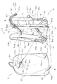
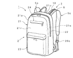
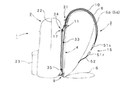
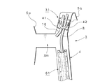
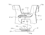
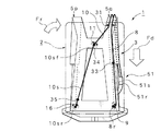
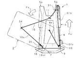
本発明の好適実施形態に係るリュックサックに備えるリュック本体部とリュック支持部の関係を示す要部の分離構成図、The isolation | separation block diagram of the principal part which shows the relationship between the rucksack main-body part and backpack support part with which the rucksack which concerns on suitable embodiment of this invention is equipped, 同リュックサックの外観斜視図、External perspective view of the rucksack, 同リュックサックに備える第一操作ロープと第二操作ロープの経路を示す側面構成図、Side configuration diagram showing the path of the first operation rope and the second operation rope provided in the rucksack, 同リュックサックに備える中間ガイド支持部の一例を示す構成図、The block diagram which shows an example of the intermediate guide support part with which the rucksack is equipped, 同リュックサックに備える上ガイド支持部の変更例を示す構成図、The block diagram which shows the example of a change of the upper guide support part with which the rucksack is equipped, 同リュックサック(リュック本体部)を背負った使用態様の背面方向から見た模式的構成を含む使用方法説明図、Use method explanatory drawing including the schematic structure seen from the back direction of the use mode which carried the rucksack (rucks body part) on the back, 同リュックサック(リュック本体部)を傾倒させた使用態様の背面方向から見た模式的構成を含む他の使用方法説明図、Other use method explanatory drawing including the typical structure seen from the back direction of the use mode which inclined the rucksack (rucks body part),

次に、本発明に係る好適実施形態を挙げ、図面に基づき詳細に説明する。   Next, preferred embodiments according to the present invention will be given and described in detail with reference to the drawings.

まず、本実施形態に係るリュックサック1の構成について、図1〜図5を参照して説明する。   First, the structure of the rucksack 1 which concerns on this embodiment is demonstrated with reference to FIGS.

図1に示すように、本実施形態に係るリュックサック1は、大別して、物品を収容可能なリュック本体部2と、このリュック本体部2に対して別体に構成したリュック支持部3とを備える。   As shown in FIG. 1, a rucksack 1 according to this embodiment is roughly divided into a rucksack main body 2 that can accommodate articles, and a rucksack support 3 that is configured separately from the rucksack main body 2. Prepare.

リュック本体部2は、広く知られている一般的なリュックサックからベルト類(左右一対の肩掛ベルトやヒップベルト等)を除いた部分、即ち、物品を収容する収容部分のみとなる。したがって、例示のリュック本体部2は、図2に示すように、上下に長い直方体状をなす本体主部21を備え、この本体主部21の上半部には、一方の側面21pから上面21uを経て他方の側面21qに至るファスナー22により開閉する出し入れ口を備えており、この出し入れ口を通して本体主部21に対する物品の出し入れを行うことができる。また、本体主部21の背面21rには、下半部に付設した下ポケット部23及び上部に付設した上ポケット部24を備えている。   The rucksack main body 2 is a portion obtained by removing belts (a pair of left and right shoulder belts, a hip belt, etc.) from a widely known general rucksack, that is, only a housing portion for housing an article. Accordingly, as shown in FIG. 2, the illustrated rucksack main body 2 includes a main body main portion 21 having a rectangular parallelepiped shape that is long in the vertical direction, and the upper half of the main body main portion 21 has an upper surface 21u from one side surface 21p. Through which the fastener 22 reaching the other side surface 21q is opened and closed, and articles can be taken in and out of the main body 21 through this outlet. The back surface 21r of the main body 21 is provided with a lower pocket portion 23 attached to the lower half portion and an upper pocket portion 24 attached to the upper portion.

一方、リュック支持部3は、図1に示すように、リュック本体部2を支持する支持ベース部4と、この支持ベース部4の上部の左右部位Xup,Xuqと当該支持ベース部4の下部の左右部位Xdp,Xdq間をそれぞれ連結する左右一対の肩掛ベルト部5p,5q,と、支持ベース部4の下部における左部位Xdpと右部位Xdq間を連結するヒップベルト部6を備え、これら支持ベース部4,肩掛ベルト部5p,5q及びヒップベルト部6は一体に構成する。この場合、支持ベース部4は、本体主部21の前面21fに重なることにより、リュック本体部2を支持する一枚のシート状に形成したものであり、例示の支持ベース部4は、上下に長い台形フレーム形である。   On the other hand, as shown in FIG. 1, the rucksack support portion 3 includes a support base portion 4 that supports the rucksack main body portion 2, left and right portions Xup and Xuq above the support base portion 4, and lower portions of the support base portion 4. A pair of left and right shoulder belt portions 5p, 5q for connecting the left and right portions Xdp, Xdq, respectively, and a hip belt portion 6 for connecting the left portion Xdp and the right portion Xdq in the lower portion of the support base 4 are provided. The portion 4, the shoulder belt portions 5p and 5q and the hip belt portion 6 are integrally formed. In this case, the support base portion 4 is formed in a single sheet shape supporting the rucksack main body portion 2 by overlapping the front surface 21f of the main body main portion 21, and the illustrated support base portion 4 is vertically Long trapezoid frame shape.

また、支持ベース部4の上部(上端部)における左部位Xup及び右部位Xuqから、それぞれ縦方向となる左側の肩掛主部5pm及び右側の肩掛主部5qmを延出させるとともに、支持ベース部4の下部(下端部)における左部位Xdp及び右部位Xdqから、それぞれ縦方向となる左側の肩掛補助部5ps及び右側の肩掛補助部5qsを延出させる。そして、肩掛主部5pmの先端と肩掛補助部5psの先端を、接続位置を調整可能な長さ調整バックル26pを介して接続するとともに、肩掛主部5qmの先端と肩掛補助部5qsの先端を、接続位置を調整可能な長さ調整バックル26qを介して接続する。これにより、支持ベース部4の上部の左右部位Xup,Xuqと当該支持ベース部4の下部の左右部位Xdp,Xdq間がそれぞれ連結(接続)される左右一対のループ状の肩掛ベルト部5p,5qが構成される。   Further, the left shoulder main portion 5pm and the right shoulder main portion 5qm in the vertical direction are extended from the left portion Xup and the right portion Xuq in the upper portion (upper end portion) of the support base portion 4, respectively. From the left part Xdp and the right part Xdq in the lower part (lower end part), the left shoulder auxiliary part 5ps and the right shoulder auxiliary part 5qs in the vertical direction are extended. And while connecting the front-end | tip of a shoulder main part 5pm and the front-end | tip of a shoulder auxiliary part 5ps via the length adjustment buckle 26p which can adjust a connection position, the front-end | tip of a shoulder main part 5qm and the front-end | tip of a shoulder auxiliary part 5qs are connected, It connects via the length adjustment buckle 26q which can adjust a connection position. As a result, a pair of left and right loop-shaped shoulder belt portions 5p, 5q in which the left and right portions Xup, Xuq at the upper portion of the support base portion 4 and the left and right portions Xdp, Xdq at the lower portion of the support base portion 4 are connected (connected), respectively. Is configured.

さらに、支持ベース部4の下部(下端部)における左部位Xdpから、横方向となる左ベルト部6pを延出させるとともに、支持ベース部4の下部(下端部)における右部位Xdqから、横方向となる右ベルト部6qを延出させる。そして、左ベルト部6pの先端と右ベルト部6qの先端をバックル(例えば、ワンタッチ式バックル)27を介して着脱可能に接続する。これにより、支持ベース部4の下部における左部位Xdpと右部位Xdq間が連結されるヒップベルト部6が構成される。なお、28はヒップベルト部6の接続位置を調整可能な長さ調整バックルを示す。   Further, the left belt portion 6p extending in the lateral direction extends from the left portion Xdp in the lower portion (lower end portion) of the support base portion 4, and the lateral portion extends from the right portion Xdq in the lower portion (lower end portion) of the support base portion 4. The right belt portion 6q is extended. And the front-end | tip of the left belt part 6p and the front-end | tip of the right belt part 6q are detachably connected via the buckle (for example, one-touch type buckle) 27. FIG. Thereby, the hip belt part 6 in which the left part Xdp and the right part Xdq in the lower part of the support base part 4 are connected is configured. Reference numeral 28 denotes a length adjustment buckle capable of adjusting the connection position of the hip belt portion 6.

他方、第一操作ロープ8と第二操作ロープ10の二本のロープ部材を用意するとともに、第一操作ロープ8及び/又は第二操作ロープ10の各経路をガイドするための四つのガイド支持部9,11,16,31を用意する。   On the other hand, while preparing the two rope members of the 1st operation rope 8 and the 2nd operation rope 10, the four guide support parts for guiding each path | route of the 1st operation rope 8 and / or the 2nd operation rope 10 are prepared. 9, 11, 16, 31 are prepared.

この場合、第一操作ロープ8の一端部8rと第二操作ロープ10の一端部10rは、後述するように、リュック本体部2の所定位置に結合するとともに、第一操作ロープ8の他端部8fと第二操作ロープ10の他端部10fは手で持つことができる操作部として用いる。この際、第一操作ロープ8の他端部8fと第二操作ロープ10の他端部10fは、共に、バックル51の雄側51sに結合する。この結果、第一操作ロープ8及び第二操作ロープ10の他端部8f,10fは一体化される。他方、バックル51の雌側51rは、肩掛ベルト部5qの所定位置に取付ける。例示の場合、連結ベルト52を用意し、この連結ベルト52の一端に雌側51rを取付けるとともに、連結ベルト52の他端を肩掛ベルト部5qの中間位置付近に取付けている。この雄側51sと雌側51rを含むバックル51は、例えば、ワンタッチバックルを用いることができる。これにより、着脱部15が構成され、一体化した他端部8f,10fは、肩掛ベルト部5qに対して着脱方式により結合される。このように構成すれば、第一操作ロープ8と第二操作ロープ10を一緒に操作可能になるため、操作の容易化を図ることができるとともに、着脱部15に対する着脱操作も一緒に、即ち、第一操作ロープ8と第二操作ロープ10の位置も同時に固定又は固定解除することができる利点がある。   In this case, the one end 8r of the first operation rope 8 and the one end 10r of the second operation rope 10 are coupled to a predetermined position of the rucksack main body 2 and the other end of the first operation rope 8 as will be described later. 8f and the other end portion 10f of the second operation rope 10 are used as an operation portion that can be held by hand. At this time, the other end 8 f of the first operation rope 8 and the other end 10 f of the second operation rope 10 are both coupled to the male side 51 s of the buckle 51. As a result, the other end portions 8f and 10f of the first operation rope 8 and the second operation rope 10 are integrated. On the other hand, the female side 51r of the buckle 51 is attached to a predetermined position of the shoulder belt portion 5q. In the case of illustration, a connecting belt 52 is prepared, a female side 51r is attached to one end of the connecting belt 52, and the other end of the connecting belt 52 is attached near the middle position of the shoulder belt portion 5q. As the buckle 51 including the male side 51s and the female side 51r, for example, a one-touch buckle can be used. Thereby, the attaching / detaching portion 15 is configured, and the integrated other end portions 8f and 10f are coupled to the shoulder belt portion 5q by an attaching / detaching method. If comprised in this way, since it becomes possible to operate the 1st operation rope 8 and the 2nd operation rope 10 together, while being able to aim at easy operation, the attachment / detachment operation with respect to the attachment / detachment part 15 is also carried out together, ie, There is an advantage that the positions of the first operation rope 8 and the second operation rope 10 can be simultaneously fixed or released.

また、各ガイド支持部9,11,16,31は、図1に示すように、リュック支持部3における背面の所定位置に取付ける。この場合、一つのガイド支持部は、図4に示すように、リュック支持部3の表面に縫付けるなどにより固定する取付プレート部41と、この取付プレート部41の表面に取付けたリング部42とを備える基本的形態を有し、このリング部42は、硬質プラスチック素材又は金属素材等により構成する。このリング部42には、第一操作ロープ8及び/又は第二操作ロープ10を通すことができる。   Moreover, each guide support part 9, 11, 16, 31 is attached to the predetermined position of the back surface in the rucksack support part 3, as shown in FIG. In this case, as shown in FIG. 4, one guide support portion includes an attachment plate portion 41 that is fixed to the surface of the rucksack support portion 3 by sewing, and a ring portion 42 that is attached to the surface of the attachment plate portion 41. The ring portion 42 is made of a hard plastic material or a metal material. The first operation rope 8 and / or the second operation rope 10 can be passed through the ring portion 42.

したがって、各ガイド支持部9,11,16,31は、リング部42の向き及び大きさ等の具体的形態がそれぞれ異なるとしても基本的形態は同じとなる。本実施形態で使用する四つのガイド支持部は、第一ガイド支持部9,上ガイド支持部11,第二ガイド支持部16及び中間ガイド支持部31となる。   Therefore, the basic forms of the guide support parts 9, 11, 16, 31 are the same even if the specific forms such as the direction and size of the ring part 42 are different. The four guide support portions used in the present embodiment are the first guide support portion 9, the upper guide support portion 11, the second guide support portion 16, and the intermediate guide support portion 31.

この場合、第一ガイド支持部9は、支持ベース部4の下部(下端部)の右部位Xdqに取付けるものであり、第一操作ロープ8が挿通し、かつ軸心が横方向に向いたリング部42を備える。上ガイド支持部11は、支持ベース部4の上部の左右中央部位Xmに取付けるものであり、第二操作ロープ10が挿通し、かつ軸心が斜めに傾斜すことにより後述する中間ガイド支持部31に向いたリング部42を備える。第二ガイド支持部16は、支持ベース部4の下部(下端部)の左部位Xdpに取付けるものであり、第二操作ロープ10(10s)が挿通し、かつ軸心が縦方向に向いたリング部42を備える。中間ガイド支持部31は、肩掛主部5qmにおける支持ベース部4の近傍に取付けるものであり、第一操作ロープ8及び第二操作ロープ10の双方が挿通し、かつ軸心が取付ける肩掛主部5qmの長手方向に沿うリング部42を有する。   In this case, the first guide support portion 9 is attached to the right portion Xdq of the lower portion (lower end portion) of the support base portion 4, and is a ring in which the first operation rope 8 is inserted and the axis is oriented in the lateral direction. The unit 42 is provided. The upper guide support portion 11 is attached to the left and right center portion Xm of the upper portion of the support base portion 4, and an intermediate guide support portion 31 to be described later when the second operation rope 10 is inserted and the axis is inclined obliquely. The ring part 42 which faces is provided. The second guide support portion 16 is attached to the left portion Xdp of the lower portion (lower end portion) of the support base portion 4, and is a ring in which the second operation rope 10 (10 s) is inserted and the axis is oriented in the vertical direction. The unit 42 is provided. The intermediate guide support portion 31 is attached in the vicinity of the support base portion 4 in the shoulder main portion 5qm, and both the first operation rope 8 and the second operation rope 10 are inserted and the shoulder main portion 5qm to which the shaft center is attached. It has the ring part 42 along the longitudinal direction.

そして、図1に示すように、第一操作ロープ8及び第二操作ロープ10の他端部8f,10fに結合したバックル51の雄側51sを肩掛主部5qmの前側に位置させるとともに、第一操作ロープ8と第二操作ロープ10の一端部8r,10r側は、中間ガイド支持部31を挿通させて後側に至らせる。中間ガイド支持部31を挿通させた第一操作ロープ8は、ストッパ部33を装着するとともに、さらに、第一ガイド支持部9に対して外側から挿通させた後、第一操作ロープ8の一端部8rは、リュック本体部2の下部の右部位Ydqに結合する。この場合、ストッパ部33は、筒状の本体を有するため、内部に第一操作ロープ8を通すとともに、この本体に設けた固定ネジ33sを締め付けることにより、第一操作ロープ8上の中途位置に固定することができる。このストッパ部33は、第一操作ロープ8を後側へ送った際に第一ガイド支持部9に係止し、リュック本体部2の傾倒角度を規制する機能を有する。   As shown in FIG. 1, the male side 51s of the buckle 51 coupled to the other end portions 8f, 10f of the first operation rope 8 and the second operation rope 10 is positioned on the front side of the shoulder main portion 5qm, and the first The end portions 8r and 10r of the operation rope 8 and the second operation rope 10 are inserted through the intermediate guide support portion 31 to reach the rear side. The first operation rope 8 through which the intermediate guide support portion 31 has been inserted is fitted with a stopper 33, and further inserted through the first guide support portion 9 from the outside, and then one end portion of the first operation rope 8. 8r couple | bonds with the right site | part Ydq of the lower part of the rucksack main-body part 2. FIG. In this case, since the stopper portion 33 has a cylindrical main body, the first operation rope 8 is passed through the stopper portion 33, and the fixing screw 33s provided in the main body is tightened to be positioned at a midway position on the first operation rope 8. Can be fixed. The stopper portion 33 has a function of locking the first guide rope 8 to the first guide support portion 9 when the first operation rope 8 is sent to the rear side and regulating the tilt angle of the rucksack main body portion 2.

この第一操作ロープ8は、一端部8rをリュック本体部2の下部の左右部位Ydp,Ydqの他方に結合し、第一操作ロープ8の他端部8f側を支持ベース部4の下部の左右部位Xdp,Xdqの他方に設けた第一ガイド支持部9を通すことにより引張操作可能となる第一の操作系を構成する。   The first operation rope 8 has one end 8 r coupled to the other of the left and right portions Ydp and Ydq at the lower part of the rucksack main body 2, and the other end 8 f of the first operation rope 8 is connected to the left and right at the lower part of the support base 4. A first operation system that allows a pulling operation by passing the first guide support portion 9 provided on the other of the parts Xdp and Xdq is configured.

一方、中間ガイド支持部31を挿通させた第二操作ロープ10は、上ガイド支持部11に対して上側から挿通させた後、リュック本体部2に取付けたストッパ部34を通し、さらに、ストッパ部35を装着する。この後、第二操作ロープ10は、第二ガイド支持部16に対して上側から挿通させた後、第二操作ロープ10の一端部10srはリュック本体部2の下部の左部位Ydpに結合する。   On the other hand, the second operation rope 10 through which the intermediate guide support portion 31 is inserted is inserted through the upper guide support portion 11 from the upper side, and then is passed through the stopper portion 34 attached to the rucksack main body portion 2. Wear 35. Thereafter, the second operation rope 10 is inserted into the second guide support portion 16 from above, and then one end portion 10sr of the second operation rope 10 is coupled to the left portion Ydp at the lower portion of the rucksack main body portion 2.

この場合、ストッパ部34は、リング状の本体を有するため、内部に第二操作ロープ10を通すことができるとともに、この本体に設けた固定ネジ34sを締め付けることにより、第二操作ロープ10上の中途位置に固定することができる。また、装着部34pに一体に設けた取付プレート部34cを、リュック本体部2の表面に縫付けるなどにより固定する。例示の場合、ストッパ部34は、リュック本体部2の前面2fにおける上部の左右中央部位Ymに取付けている。この左右中央部位Ymは、リュック支持部3における上部の左右中央部位Xmに対応する部位となる。したがって、ストッパ部34は、第二操作ロープ10を前側に引張った際に、上ガイド支持部11に係止し、リュック本体部2を背負い位置、即ち、リュック本体部2の上部における左右中央を、使用者の背中の左右中央位置に規制するストッパ機構部17が構成される。   In this case, since the stopper part 34 has a ring-shaped main body, the second operation rope 10 can be passed through the inside, and by tightening a fixing screw 34s provided on the main body, Can be fixed in the middle position. Further, the mounting plate 34c provided integrally with the mounting portion 34p is fixed to the surface of the rucksack main body 2 by sewing. In the case of illustration, the stopper portion 34 is attached to the upper left and right central portion Ym of the front surface 2 f of the rucksack main body portion 2. The left and right central portion Ym is a portion corresponding to the upper left and right central portion Xm in the backpack support portion 3. Therefore, when the second operation rope 10 is pulled forward, the stopper portion 34 is locked to the upper guide support portion 11 so that the backpack body portion 2 is placed on the back, that is, the left and right center at the upper portion of the backpack body portion 2. The stopper mechanism 17 is configured to restrict the center of the user's back to the left and right.

また、ストッパ部35は、筒状の本体を有するため、内部に第二操作ロープ10を通すとともに、この本体に設けた固定ネジ35sを締め付けることにより、第二操作ロープ10上の中途位置、特に、リュック本体部2における下部の左部位Ydpの近傍に固定する。このストッパ部35は、第二操作ロープ10を後側へ送った際に第二ガイド支持部16に係止し、リュック本体部2を傾倒させる際の支点支持部7として機能する。   Moreover, since the stopper part 35 has a cylindrical main body, while passing the 2nd operation rope 10 inside, by tightening the fixing screw 35s provided in this main body, the halfway position on the 2nd operation rope 10, especially The lower left part Ydp of the rucksack main body 2 is fixed in the vicinity. The stopper portion 35 is locked to the second guide support portion 16 when the second operation rope 10 is sent to the rear side, and functions as the fulcrum support portion 7 when the backpack body portion 2 is tilted.

したがって、第二操作ロープ10は、一端部10rをリュック本体部2の上部の左右中央部位Ymに結合し、第二操作ロープ10の他端部10f側を支持ベース部4の上部の左右中央部位Xmに設けた上ガイド支持部11を通すことにより引張操作可能となる第二の操作系を構成する。なお、例示の場合、ストッパ部34とリュック本体部2の下部の左部位Ydpに結合した一端部10sr間には、第二操作ロープ10の一部が設けられるため、この部分は、ハンドル部10sとして機能させることができる。したがって、第二操作ロープ10におけるストッパ部34の位置は、第二操作ロープ10の実質的な一端部10rとなると同時にハンドル部10sの他端部10sfとなる。このため、ハンドル部10sを設けることなく、第二操作ロープ10の一端部をストッパ部34の位置に直接固定することによりストッパ機構部17を構成する場合を排除するものではなく、この場合には、支点支持部7を単純な回動部として構成できる。   Therefore, the second operation rope 10 has one end portion 10r connected to the left and right central portion Ym on the upper portion of the rucksack body portion 2, and the other end portion 10f side of the second operation rope 10 is connected to the left and right central portion on the upper portion of the support base portion 4. A second operation system that allows a pulling operation by passing the upper guide support portion 11 provided in Xm is configured. In the illustrated example, a part of the second operation rope 10 is provided between the stopper portion 34 and the one end portion 10sr coupled to the lower left portion Ydp of the rucksack main body portion 2, so that this portion is the handle portion 10s. Can function as. Therefore, the position of the stopper portion 34 in the second operation rope 10 becomes the substantial one end portion 10r of the second operation rope 10 and the other end portion 10sf of the handle portion 10s. For this reason, the case where the stopper mechanism portion 17 is configured by directly fixing one end portion of the second operation rope 10 to the position of the stopper portion 34 without providing the handle portion 10s is not excluded. The fulcrum support portion 7 can be configured as a simple rotation portion.

このように、第二操作ロープ10を設けるに際し、一端部10rをリュック本体部2の下部の左右部位Ydp,Ydqの一方に結合し、他端部10f側を支持ベース部4の下部の左右部位Xdp,Xdqの一方に設けた第二ガイド支持部16及び上ガイド支持部11を通すことにより引張操作可能に構成するとともに、上ガイド支持部11と第二操作ロープ10間には、上ガイド支持部11に対して第二操作ロープ10の所定位置を固定又は規制するストッパ機構部17を設けて構成すれば、第二ガイド支持部16と上ガイド支持部11間に設けられる第二操作ロープ10の部分は、使用者が手で持つことができるハンドル部10sとして機能させることができるため、補助操作用に利用できる利点がある。加えて、ストッパ機構部17を設けたため、傾倒したリュック本体部2を元の背負い状態に戻す際には、背中の中央位置に対して容易に位置決めすることができる。   As described above, when the second operation rope 10 is provided, the one end portion 10r is coupled to one of the left and right portions Ydp and Ydq in the lower portion of the rucksack main body portion 2, and the other end portion 10f side is coupled to the left and right portions in the lower portion of the support base portion 4. The second guide support portion 16 and the upper guide support portion 11 provided on one of Xdp and Xdq are configured to be capable of pulling operation, and the upper guide support portion 11 and the second operation rope 10 are provided with an upper guide support. If the stopper mechanism part 17 which fixes or restricts the predetermined position of the second operation rope 10 with respect to the part 11 is provided, the second operation rope 10 provided between the second guide support part 16 and the upper guide support part 11 is configured. This part has the advantage that it can be used for auxiliary operation because it can function as the handle part 10s that the user can hold by hand. In addition, since the stopper mechanism portion 17 is provided, the tilted backpack body portion 2 can be easily positioned with respect to the center position of the back when the backpack body portion 2 is returned to the original backpack state.

なお、例示した各ガイド支持部9,11,16,31の形態(形状及び構成)は一例であり、例示の形態に限定されるものではない。即ち、第一操作ロープ8と第二操作ロープ10を円滑にガイドする機能を有すれば足り、配置する部位(位置)や数量は任意に選定できる。   In addition, the form (shape and structure) of each illustrated guide support part 9, 11, 16, 31 is an example, and is not limited to the illustrated form. That is, it suffices to have a function of smoothly guiding the first operation rope 8 and the second operation rope 10, and the site (position) and quantity to be arranged can be arbitrarily selected.

例えば、必要により、更なる追加の中間ガイド支持部を設けてもよい。図4には、中間ガイド支持部31と第二ガイド支持部9(図1)間に、追加の中間ガイド支持部61を設けた例を示す。この中間ガイド支持部61の形態は、第一操作ロープ8を通すことができるトンネル状に形成したものであり、適度に湾曲するプラスチック素材等で形成することができる。   For example, if necessary, an additional intermediate guide support may be provided. FIG. 4 shows an example in which an additional intermediate guide support 61 is provided between the intermediate guide support 31 and the second guide support 9 (FIG. 1). The form of the intermediate guide support portion 61 is formed in a tunnel shape through which the first operation rope 8 can pass, and can be formed of a plastic material or the like that is appropriately curved.

一方、図5は、上ガイド支持部11の形態を変更した例を示す。図5に示す上ガイド支持部11eは、剛性を有する硬質プラスチック素材等で形成し、左右方向に長いトンネル状に形成したものである。この際、上ガイド支持部11eにおける肩掛ベルト部5q側の開口部61uは、中間ガイド支持部31側を向くように斜め上方へ湾曲させるとともに、上ガイド支持部11eにおける第一ガイド支持部16(図1参照)側の開口部61dは、当該第一ガイド支持部9側を向くように斜め下方へ湾曲させる。さらに、上ガイド支持部62の上下方向中央位置には、第一ガイド支持部9側の開口から長手方向の中央位置まで、ガイドスリット部62sを形成するとともに、他方、リュック本体部2の前面2fにおける上部左右中央部位Ymに取付けたストッパ部34は、図5に示すように、装着部34pと取付プレート部34c間を係合ピン34gを介して連結し、この係合ピン34gがガイドスリット部62sに係合してガイドされるように構成する。このため、ガイドスリット部62sの開口側は、係合ピン34gを円滑に受け入れることができるように外側広がり形状に形成することが望ましい。図5に示す変更例では、背負い位置のリュック本体部2が傾倒する際に、所定の角度まで背中に沿って変位させることができる利点がある。   On the other hand, FIG. 5 shows an example in which the form of the upper guide support portion 11 is changed. The upper guide support portion 11e shown in FIG. 5 is made of a hard plastic material having rigidity and is formed in a tunnel shape that is long in the left-right direction. At this time, the opening 61u on the shoulder belt portion 5q side of the upper guide support portion 11e is bent obliquely upward so as to face the intermediate guide support portion 31 side, and the first guide support portion 16 ( The opening 61d on the side is bent obliquely downward so as to face the first guide support 9 side. Furthermore, a guide slit portion 62s is formed from the opening on the first guide support portion 9 side to the center position in the longitudinal direction at the center position in the vertical direction of the upper guide support portion 62. On the other hand, the front surface 2f of the rucksack body portion 2 is formed. As shown in FIG. 5, the stopper portion 34 attached to the upper left and right central portion Ym connects the mounting portion 34p and the attachment plate portion 34c via an engagement pin 34g, and the engagement pin 34g is connected to the guide slit portion. It is configured to be guided by engaging with 62s. For this reason, it is desirable that the opening side of the guide slit portion 62s be formed in an outwardly expanded shape so that the engaging pin 34g can be smoothly received. In the modification shown in FIG. 5, there is an advantage that when the backpack main body portion 2 at the back position tilts, it can be displaced along the back to a predetermined angle.

次に、本実施形態に係るリュックサック1の使用方法について、図6及び図7を参照して説明する。   Next, the usage method of the rucksack 1 which concerns on this embodiment is demonstrated with reference to FIG.6 and FIG.7.

まず、通常の使用時となる背負モードについて説明する。図6は背負モードの状態を示す。背負モードでは、第一操作ロープ8及び第二操作ロープ10の先端に設けたバックル51の雄側51sを白抜矢印Fd方向に引くことにより雌側51rに装着すればよい。この際、リュック本体部2は、どのような位置(角度)にあっても、第一操作ロープ8と第二操作ロープ10により引張られるため、白抜矢印Fr方向に変位し、ストッパ部34が上ガイド支持部11eに係止した位置で変位が規制されて停止する。また、バックル27における左ベルト部6pの先端と右ベルト部6qの先端を装着して使用者の腰にヒップベルト部6を装着する。   First, the backpacking mode during normal use will be described. FIG. 6 shows the state of the back negative mode. In the backside mode, the male side 51s of the buckle 51 provided at the tips of the first operation rope 8 and the second operation rope 10 may be attached to the female side 51r by pulling in the white arrow Fd direction. At this time, the backpack main body 2 is pulled by the first operation rope 8 and the second operation rope 10 regardless of the position (angle), and thus is displaced in the direction of the white arrow Fr. Displacement is restricted and stopped at a position locked to the upper guide support portion 11e. In addition, the tip of the left belt portion 6p and the tip of the right belt portion 6q in the buckle 27 are attached, and the hip belt portion 6 is attached to the user's waist.

これにより、リュック本体部2は背負い位置、即ち、リュック本体部2の左右中央位置が使用者の背中の左右中央位置に一致する背負モードとなる。したがって、背負モードでのリュックサック1は、一般的なリュックサックと同様に、使用者は、リュック支持部3における一方の肩掛ベルト部5pを自身の左肩に掛け、他方の肩掛ベルト部5qを自身の右肩に掛けることにより背中に背負うことができる。   Thereby, the rucksack main-body part 2 becomes a back-loading mode in which the back-and-forth position, that is, the left-right center position of the back-pack body part 2 coincides with the left-right center position of the user's back. Therefore, in the backpack 1 in the backpack mode, similarly to a general rucksack, the user hangs one shoulder belt portion 5p of the backpack support portion 3 on his / her left shoulder and the other shoulder belt portion 5q himself / herself. You can carry it on your back by hanging it on your right shoulder.

次に、背負ったまま物品の出し入れを行うことができる傾倒モードについて説明する。図7は傾倒モードの状態を示す。傾倒モードでは、図7に示すように、バックル51の雄側51sを雌側51rから離脱させればよい。これにより、リュック本体部2の傾倒が許容されることになる。   Next, a tilt mode in which an article can be taken in and out while being carried on the back will be described. FIG. 7 shows the state of the tilt mode. In the tilt mode, as shown in FIG. 7, the male side 51s of the buckle 51 may be detached from the female side 51r. Thereby, the inclination of the rucksack main-body part 2 is accept | permitted.

したがって、使用者は、バックル51の雄側51sを手で持ちながら、例えば、身体を稍傾倒させたり、或いは身体を振るなどにより、リュック本体部2を、図7に示す白抜矢印Fs方向に変位するように誘導すればよい。これにより、リュック本体部2は、支点支持部7を回動支点として白抜矢印Fs方向に回動変位する。この場合、リュック本体部2の自重等により傾倒するため、第一操作ロープ8と第二操作ロープ10、更にはハンドル部10sを操作することにより、安定した状態で傾倒させることができる。特に、ハンドル部10sは、使用者が手で持つことによりリュック本体部2を背中から離れないように引き寄せるなどの補助操作に利用できる。   Accordingly, the user holds the male side 51s of the buckle 51 with his / her hand, for example, tilts his body or shakes his / her body so that the rucksack body 2 is moved in the direction of the white arrow Fs shown in FIG. What is necessary is just to guide so that it may displace. Thereby, the rucksack main-body part 2 is rotationally displaced in the white arrow Fs direction by using the fulcrum support part 7 as a rotational fulcrum. In this case, since it tilts due to its own weight or the like of the rucksack main body 2, it can be tilted in a stable state by operating the first operation rope 8, the second operation rope 10, and further the handle portion 10s. In particular, the handle portion 10 s can be used for auxiliary operations such as pulling the rucksack main body portion 2 so as not to leave the back when the user holds the handle portion by hand.

また、第一操作ロープ8と第二操作ロープ10は、リュック本体部2の変位に追従して後方へ引張られるため、バックル51の雄側51sも、図7に示すように、白抜矢印Fu方向に変位する。そして、第一操作ロープ8に設けたストッパ部33が第二ガイド支持部9に係止した位置で変位が規制されて停止する。この停止した位置におけるリュック本体部2は、図7に示すように傾倒するため、使用者は、リュックサック1を背負ったまま物品の出し入れを行うことが可能となる。他方、物品の出し入れが終了したなら、上述した図6に示す操作に従って背負モードに戻せばよい。   Further, since the first operation rope 8 and the second operation rope 10 are pulled backward following the displacement of the rucksack main body 2, the male side 51 s of the buckle 51 also has a white arrow Fu as shown in FIG. 7. Displace in the direction. Then, the displacement is restricted and stopped at the position where the stopper portion 33 provided on the first operation rope 8 is locked to the second guide support portion 9. Since the rucksack body 2 in the stopped position is tilted as shown in FIG. 7, the user can put in and out the article while carrying the rucksack 1 on the back. On the other hand, when the taking in / out of the article is completed, the backpacking mode may be returned according to the operation shown in FIG.

よって、このような本実施形態に係るリュックサック1によれば、基本形態として、物品を収容可能なリュック本体部2と、このリュック本体部2に対して別体に構成したリュック支持部3とを備え、このリュック支持部3は、リュック本体部2を支持する支持ベース部4,この支持ベース部4の上部の左右部位Xup,Xuqと当該支持ベース部4の下部の左右部位Xdp,Xdq間をそれぞれ連結可能な左右一対の肩掛ベルト部5p,5q,及び当該支持ベース部4の下部における左部位Xdpと右部位Xdq間を連結可能なヒップベルト部6を備えて構成するとともに、リュック本体部2の下部の左部位Ydpを、支持ベース部4の下部の左部位Xdpに設けた支点支持部7により回動可能に支持し、かつ第一操作ロープ8の一端部8rをリュック本体部2の下部の右部位Ydqに結合し、第一操作ロープ8の他端部8f側を支持ベース部4の下部の右部位Xdqに設けた第一ガイド支持部9を通すことにより引張操作可能に構成するとともに、第二操作ロープ10の一端部10rをリュック本体部2の上部の左右中央部位Ymに結合し、第二操作ロープ10の他端部10f側を支持ベース部4の上部の左右中央部位Xmに設けた上ガイド支持部11を通すことにより引張操作可能に構成してなるため、リュック支持部3に設けた支点支持部7を支点にして、リュック本体部2を背中に背負った状態で傾倒させることができる。したがって、登山用リュックザックのように比較的大きくて重いリュックサック1の場合であっても、リュックサック1を背中に背負ったままリュック本体部2に対する物品の出し入れが可能なり、背中から降ろすことなく物品の出し入れを可能にするリュックサックの範囲を飛躍的に拡大できるなど、汎用性及び発展性を高めることができる。したがって、特に、登山用リュックザックに用いて最適となる。   Therefore, according to the rucksack 1 according to this embodiment, as a basic form, the rucksack main body 2 that can accommodate articles, and the rucksack support 3 configured separately from the rucksack main body 2, The rucksack support portion 3 includes a support base portion 4 that supports the rucksack main body portion 4, and a portion between the left and right portions Xup and Xuq above the support base portion 4 and the left and right portions Xdp and Xdq below the support base portion 4. And a pair of left and right shoulder belt portions 5p, 5q that can be connected to each other, and a hip belt portion 6 that can connect the left portion Xdp and the right portion Xdq at the lower portion of the support base portion 4, and a rucksack main body portion 2 is supported by a fulcrum support portion 7 provided in the lower left portion Xdp of the support base portion 4, and one end portion 8 of the first operation rope 8. Is coupled to the lower right portion Ydq of the rucksack main body 2 and the other end portion 8f side of the first operation rope 8 is passed through the first guide support portion 9 provided in the lower right portion Xdq of the support base portion 4. The second operation rope 10 is configured so that it can be pulled, and one end portion 10r of the second operation rope 10 is coupled to the left and right central portion Ym of the upper portion of the rucksack body portion 2, and the other end portion 10f side of the second operation rope 10 is connected to the support base portion 4. Since the upper guide support part 11 provided in the upper left and right central part Xm is configured to be able to perform a pulling operation, the fulcrum support part 7 provided in the rucksack support part 3 is used as a fulcrum and the backpack body part 2 is placed on the back. It can be tilted while carrying on the back. Therefore, even in the case of a relatively large and heavy rucksack 1 such as a mountaineering rucksack, articles can be taken in and out of the rucksack main body 2 while the rucksack 1 is carried on the back, and it is possible to remove it from the back. The versatility and developability can be enhanced, for example, the range of the rucksack that allows the articles to be taken in and out can be dramatically expanded. Therefore, it is particularly suitable for use in mountaineering rucksacks.

また、背中に背負ったリュック本体部2を傾倒させるに際しては、第一操作ロープ8及び第二操作ロープ10の操作、即ち、第一操作ロープ8及び第二操作ロープ10の位置の固定を解除すれば、リュック本体部2の自重等により容易に傾倒させることができるとともに、他方、傾倒したリュック本体部2を元の背負い状態に戻す場合には、第一操作ロープ8及び第二操作ロープ10を引張るのみでよく、リュック本体部2に対して物品の出し入れを行う際の操作はきわめて容易に行うことができるなど、操作のための労力を軽減し、使い勝手及び利便性を高めることができる。   Further, when tilting the rucksack main body 2 carried on the back, the operation of the first operation rope 8 and the second operation rope 10, that is, the positions of the first operation rope 8 and the second operation rope 10 are released. For example, the first operation rope 8 and the second operation rope 10 can be easily tilted due to the weight of the rucksack main body 2 and, on the other hand, when the tilted rucksack main body 2 is returned to its original state, It is only necessary to pull, and the operation for putting the article in and out of the rucksack main body 2 can be performed very easily. For example, the labor for the operation can be reduced, and the usability and convenience can be improved.

以上、変更例を含む好適実施形態について詳細に説明したが、本発明は、このような実施形態に限定されるものではなく、細部の構成,形状,素材,数量,数値等において、本発明の要旨を逸脱しない範囲で、任意に変更,追加,削除することができる。   The preferred embodiments including the modified examples have been described in detail above. However, the present invention is not limited to such embodiments, and the detailed configuration, shape, material, quantity, numerical values, and the like of the present invention are not limited thereto. Changes, additions and deletions can be made arbitrarily without departing from the scope.

例えば、実施形態では、右効き用として構成した例を示したが、この右効き用に対して左右対称となる左効き用に構成してもよいし、必要により、どちらかを選択できる切換方式に構成することも可能である。また、リュック本体部2及びリュック支持部3の具体的な形状や構成は一例として挙げたものであり、同様の機能を有するものであれば、各種形状や構成により実施できる。さらに、第一操作ロープ8と第二操作ロープ10は、他端部8f,10fを一体化した例を挙げたが、それぞれ別々の着脱部15…により着脱できるようにしてもよい。なお、着脱部15は、第一操作ロープ8及び第二操作ロープ10を任意の位置に固定し又は固定解除できる機能を有すれば足り、その構成は問わない。一方、各ストッパ部33…は固定ネジ33s…を緩めたり締付けることにより、各操作ロープ8…上における固定位置を調整(変更)することができる。   For example, in the embodiment, an example configured for right effect is shown, but it may be configured for left effect that is bilaterally symmetrical with respect to this right effect, and a switching method in which either can be selected as necessary. It is also possible to configure. Moreover, the specific shape and structure of the rucksack main-body part 2 and the rucksack support part 3 are mentioned as an example, and if it has the same function, it can implement with various shapes and structures. Furthermore, although the first operation rope 8 and the second operation rope 10 have been described with an example in which the other end portions 8f and 10f are integrated, the first operation rope 8 and the second operation rope 10 may be detachable by separate attachment / detachment portions 15. The attaching / detaching portion 15 is sufficient if it has a function of fixing or releasing the first operation rope 8 and the second operation rope 10 at arbitrary positions, and the configuration thereof is not limited. On the other hand, each stopper portion 33 can adjust (change) the fixing position on each operation rope 8 by loosening or tightening the fixing screws 33s.

本発明に係るリュックサックは、登山用リュックザックをはじめ、物品を収容するリュック本体を左右の肩掛ベルトにより背中に背負う各種のリュックサックに利用できる。   The rucksack according to the present invention can be used for various types of rucksacks, such as mountaineering rucksacks, carrying a backpack body that houses articles on the back by left and right shoulder belts.

1:リュックサック,2:リュック本体部,3:リュック支持部,4:支持ベース部,5p:肩掛ベルト部,5q:肩掛ベルト部,6:ヒップベルト部,7:支点支持部,8:第一操作ロープ,8r:第一操作ロープの一端部,8f:第一操作ロープの他端部,9:第二ガイド支持部,10:第二操作ロープ,10r:第二操作ロープの一端部,10f:第二操作ロープの他端部,11:上ガイド支持部,15:着脱部,16:第一ガイド支持部,17:ストッパ機構部,Xup:支持ベース部の上部の左部位,Xuq:支持ベース部の上部の右部位,Xdp:支持ベース部の下部の左部位,Xdq:支持ベース部の下部の右部位,Xm:支持ベース部の上部の左右中央部位,Ydp:リュック本体部の下部の左部位,Ydq:リュック本体部の下部の右部位,Ym:リュック本体部の上部の左右中央部位   1: rucksack, 2: rucksack main body, 3: rucksack support, 4: support base, 5p: shoulder belt, 5q: shoulder belt, 6: hip belt, 7: fulcrum support, 8: first 1 operation rope, 8r: one end of the first operation rope, 8f: other end of the first operation rope, 9: second guide support, 10: second operation rope, 10r: one end of the second operation rope, 10f: the other end portion of the second operation rope, 11: upper guide support portion, 15: detachable portion, 16: first guide support portion, 17: stopper mechanism portion, Xup: upper left portion of the support base portion, Xuq: Upper part of the support base part, Xdp: Left part of the lower part of the support base part, Xdq: Right part of the lower part of the support base part, Xm: Left and right center part of the upper part of the support base part, Ydp: Lower part of the rucksack main body part Left part of Ydq: rucksack body Bottom of the right site, Ym: left and right central portion of the upper portion of the backpack body portion

Claims (4)

左右一対の肩掛ベルトにより背中に背負うことができる物品を収容可能なリュック本体部を備えるリュックサックにおいて、物品を収容可能なリュック本体部と、このリュック本体部に対して別体に構成したリュック支持部とを備え、このリュック支持部は、前記リュック本体部を支持する支持ベース部,この支持ベース部の上部の左右部位と当該支持ベース部の下部の左右部位間をそれぞれ連結可能な左右一対の肩掛ベルト部,及び当該支持ベース部の下部における左部位と右部位間を連結可能なヒップベルト部を備えて構成するとともに、前記リュック本体部の下部の左右部位の一方を、前記支持ベース部の下部の左右部位の一方に設けた支点支持部により回動可能に支持し、かつ第一操作ロープの一端部を前記リュック本体部の下部の左右部位の他方に結合し、第一操作ロープの他端部側を前記支持ベース部の下部の左右部位の他方に設けた第一ガイド支持部を通すことにより引張操作可能に構成するとともに、第二操作ロープの一端部を前記リュック本体部の上部の左右中央部位に結合し、第二操作ロープの他端部側を前記支持ベース部の上部の左右中央部位に設けた上ガイド支持部を通すことにより引張操作可能に構成してなることを特徴とするリュックサック。   In a rucksack comprising a rucksack main body that can accommodate articles that can be carried on the back by a pair of left and right shoulder belts, a rucksack main body that can accommodate articles and a rucksack support that is configured separately from the rucksack main body The rucksack support portion includes a support base portion that supports the rucksack main body portion, a pair of left and right portions that are connectable between the left and right portions of the upper portion of the support base portion and the left and right portions of the lower portion of the support base portion. A shoulder belt portion and a hip belt portion capable of connecting between the left portion and the right portion in the lower portion of the support base portion are configured, and one of the left and right portions in the lower portion of the rucksack main body portion is connected to the support base portion. The fulcrum support part provided on one of the left and right parts of the lower part is rotatably supported, and one end of the first operation rope is attached to the lower part of the rucksack main body part. It is coupled to the other of the right part, and the other end side of the first operation rope is configured to be tensionable by passing through the first guide support part provided on the other of the left and right parts below the support base part. One end of the two operation ropes is joined to the left and right central part of the upper part of the rucksack main body part, and the other end part of the second operation rope is passed through the upper guide support part provided in the left and right central part of the upper part of the support base part. A rucksack characterized by being configured to be capable of being pulled. 前記第一操作ロープと前記第二操作ロープは他端部を一体化するとともに、この一体化した他端部は、着脱部を介して前記肩掛ベルト部の一方に着脱方式により結合することを特徴とする請求項1記載のリュックサック。   The first operation rope and the second operation rope are integrated at the other end portion, and the integrated other end portion is coupled to one of the shoulder belt portions by an attachment / detachment method via an attachment / detachment portion. The rucksack according to claim 1. 前記第二操作ロープは、一端部を前記リュック本体部の下部の左右部位の一方に結合し、他端部側を前記支持ベース部の下部の左右部位の一方に設けた第二ガイド支持部及び前記上ガイド支持部を通すことにより引張操作可能に構成するとともに、前記上ガイド支持部と前記第二操作ロープ間には、前記上ガイド支持部に対して前記第二操作ロープの所定位置を固定又は規制するストッパ機構部を備えることを特徴とする請求項1又は2記載のリュックサック。   The second operation rope has one end coupled to one of the left and right portions of the lower portion of the rucksack main body, and the other end portion provided on one of the left and right portions of the lower portion of the support base portion; The upper guide support portion is configured so that it can be pulled, and a predetermined position of the second operation rope is fixed between the upper guide support portion and the second operation rope with respect to the upper guide support portion. The rucksack according to claim 1 or 2, further comprising a stopper mechanism portion for regulating. 前記リュックサックとして、登山用のリュックザックに適用することを特徴とする請求項1,2又は3記載のリュックサック。   4. The rucksack according to claim 1, wherein the rucksack is applied to a backpack for mountain climbing.
JP2016083323A 2016-04-19 2016-04-19 rucksack Active JP6182712B1 (en)

Priority Applications (1)

Application Number Priority Date Filing Date Title
JP2016083323A JP6182712B1 (en) 2016-04-19 2016-04-19 rucksack

Applications Claiming Priority (1)

Application Number Priority Date Filing Date Title
JP2016083323A JP6182712B1 (en) 2016-04-19 2016-04-19 rucksack

Publications (2)

Publication Number Publication Date
JP6182712B1 JP6182712B1 (en) 2017-08-23
JP2017192473A true JP2017192473A (en) 2017-10-26

Family

ID=59678236

Family Applications (1)

Application Number Title Priority Date Filing Date
JP2016083323A Active JP6182712B1 (en) 2016-04-19 2016-04-19 rucksack

Country Status (1)

Country Link
JP (1) JP6182712B1 (en)

Cited By (2)

* Cited by examiner, † Cited by third party
Publication number Priority date Publication date Assignee Title
KR102388441B1 (en) * 2021-11-30 2022-04-20 조수아 Retractor for backpack
US12185823B2 (en) 2019-07-24 2025-01-07 Hiroaki Ota Backpack and backpack set

Citations (2)

* Cited by examiner, † Cited by third party
Publication number Priority date Publication date Assignee Title
US5954253A (en) * 1996-06-26 1999-09-21 Johnson Worldwide Associates, Inc. Flexible frame load carrying system
JP2015532600A (en) * 2012-06-27 2015-11-12 エックスデザイン,エルエルシー Backpack system and articulated frame

Patent Citations (2)

* Cited by examiner, † Cited by third party
Publication number Priority date Publication date Assignee Title
US5954253A (en) * 1996-06-26 1999-09-21 Johnson Worldwide Associates, Inc. Flexible frame load carrying system
JP2015532600A (en) * 2012-06-27 2015-11-12 エックスデザイン,エルエルシー Backpack system and articulated frame

Cited By (2)

* Cited by examiner, † Cited by third party
Publication number Priority date Publication date Assignee Title
US12185823B2 (en) 2019-07-24 2025-01-07 Hiroaki Ota Backpack and backpack set
KR102388441B1 (en) * 2021-11-30 2022-04-20 조수아 Retractor for backpack

Also Published As

Publication number Publication date
JP6182712B1 (en) 2017-08-23

Similar Documents

Publication Publication Date Title
US5462214A (en) Body mounted camera support assembly
FI98264C (en) Baby carrier harness
EP0480573B1 (en) Waist bag
US6138881A (en) Convertible backpack/shoulder bag
EP1947978B1 (en) System for carrying articles at the front torso of a human being
US20090084821A1 (en) Convertible backpack frame
US6672321B2 (en) Apparatus for containing and centering oxygen bottle on a walker
US5005744A (en) Adjustable backpack
EP1629748A1 (en) Infant carrier with hood
US10051948B2 (en) Utility belt
US20050103817A1 (en) Combination carrying bag
JP6182712B1 (en) rucksack
US5598963A (en) Body mounted camera support assembly
US20210169237A1 (en) Child carrying device
JPH1146938A (en) Bridge belt mobile baby carrier
US20090194570A1 (en) Carrier for releasably attaching to a shoulder strap and releasably carrying a pop-up umbrella
JP3207786U (en) Umbrella support
JP3196603U (en) Handlebar bag
KR100724546B1 (en) Portable camera belt
JP2003174916A (en) Shoulder belt and bag with shoulder belt
US20140117065A1 (en) Backpack with Adjustable Strap
KR102110957B1 (en) Back pack
JP4105743B2 (en) Shoulder bag with umbrella support bag
JP2533737B2 (en) Mobile bag
JP2012120786A (en) Backpack

Legal Events

Date Code Title Description
A01 Written decision to grant a patent or to grant a registration (utility model)

Free format text: JAPANESE INTERMEDIATE CODE: A01

Effective date: 20170510

A711 Notification of change in applicant

Free format text: JAPANESE INTERMEDIATE CODE: A711

Effective date: 20170523

A61 First payment of annual fees (during grant procedure)

Free format text: JAPANESE INTERMEDIATE CODE: A61

Effective date: 20170523

A521 Written amendment

Free format text: JAPANESE INTERMEDIATE CODE: A821

Effective date: 20170523

R150 Certificate of patent or registration of utility model

Ref document number: 6182712

Country of ref document: JP

Free format text: JAPANESE INTERMEDIATE CODE: R150

R154 Certificate of patent or utility model (reissue)

Free format text: JAPANESE INTERMEDIATE CODE: R154