JP2017192629A - Measurement device, measurement method, and electronic apparatus - Google Patents
Measurement device, measurement method, and electronic apparatus Download PDFInfo
- Publication number
- JP2017192629A JP2017192629A JP2016086042A JP2016086042A JP2017192629A JP 2017192629 A JP2017192629 A JP 2017192629A JP 2016086042 A JP2016086042 A JP 2016086042A JP 2016086042 A JP2016086042 A JP 2016086042A JP 2017192629 A JP2017192629 A JP 2017192629A
- Authority
- JP
- Japan
- Prior art keywords
- signal
- light
- unit
- light receiving
- living body
- Prior art date
- Legal status (The legal status is an assumption and is not a legal conclusion. Google has not performed a legal analysis and makes no representation as to the accuracy of the status listed.)
- Pending
Links
Images

Landscapes
- Measuring Pulse, Heart Rate, Blood Pressure Or Blood Flow (AREA)
Abstract
Description
本開示は、生体情報の計測に用いられる計測装置、そのような計測装置において用いられる計測方法、およびそのような計測装置を備えた電子機器に関する。 The present disclosure relates to a measuring device used for measuring biological information, a measuring method used in such a measuring device, and an electronic apparatus including such a measuring device.
生体における血流を計測する血流計の一つに、レーザードップラー血流計がある。このレーザードップラー血流計では、光源から生体に照射されたコヒーレント光が、生体内の細胞膜や小器官などにより散乱され、散乱された光のうちの一部が後方散乱光として生体外部に放出され、受光部により受光される。その際、例えば、血管中の血液(特に赤血球)により散乱された場合には、散乱光の波長は、血液の流れに応じて、トップラー現象により変化(ドップラーシフト)する。レーザードップラー血流計では、このドップラー現象を利用して、生体における血流を計測するようになっている。例えば特許文献1には、2つの光電変換素子を設け、各光電変換素子から供給された信号の差分に基づいて血流を計測する装置が開示されている。
One of the blood flow meters that measure blood flow in a living body is a laser Doppler blood flow meter. In this laser Doppler blood flow meter, the coherent light irradiated to the living body from the light source is scattered by cell membranes and small organs in the living body, and a part of the scattered light is emitted outside the living body as backscattered light. The light is received by the light receiving unit. At this time, for example, when scattered by blood (especially red blood cells) in blood vessels, the wavelength of the scattered light changes (Doppler shift) by the topler phenomenon according to the blood flow. The laser Doppler blood flow meter measures blood flow in a living body using this Doppler phenomenon. For example,
ところで、一般に、計測装置では、計測精度が高いことが望まれており、さらなる計測精度の向上が期待されている。 Incidentally, in general, a measurement apparatus is desired to have high measurement accuracy, and further improvement in measurement accuracy is expected.
計測精度を高めることができる計測装置、計測方法、および電子機器を提供することが望ましい。 It is desirable to provide a measurement device, a measurement method, and an electronic device that can increase measurement accuracy.
本開示の一実施の形態に係る計測装置は、光源と、第1の受光部と、第2の受光部と、第1の変換部と、第2の変換部と、処理部とを備えている。光源は、コヒーレント光を出射するものである。第1の変換部は、第1の受光部による受光結果をAD変換することにより第1の信号を生成するものである。第2の変換部は、第2の受光部による受光結果をAD変換することにより第2の信号を生成するものである。処理部は、第1の信号および第2の信号に基づいて、所定の処理を行うものである。 A measurement device according to an embodiment of the present disclosure includes a light source, a first light receiving unit, a second light receiving unit, a first conversion unit, a second conversion unit, and a processing unit. Yes. The light source emits coherent light. The first converter generates a first signal by AD converting the light reception result of the first light receiver. The second conversion unit generates a second signal by performing AD conversion on a light reception result obtained by the second light receiving unit. The processing unit performs predetermined processing based on the first signal and the second signal.
本開示の一実施の形態に係る計測方法は、コヒーレント光を出射し、コヒーレント光に基づく第1の光を受光するとともに、コヒーレント光に基づく第2の光を受光し、第1の光の受光結果をAD変換することにより第1の信号を生成するとともに、第2の光の受光結果をAD変換することにより第2の信号を生成し、第1の信号および第2の信号に基づいて、所定の処理を行うものである。 A measurement method according to an embodiment of the present disclosure emits coherent light, receives first light based on the coherent light, receives second light based on the coherent light, and receives the first light. A first signal is generated by A / D conversion of the result, and a second signal is generated by A / D conversion of the light reception result of the second light. Based on the first signal and the second signal, A predetermined process is performed.
本開示の一実施の形態に係る電子機器は、光源と、第1の受光部と、第2の受光部と、第1の変換部と、第2の変換部と、処理部とを備えている。光源は、コヒーレント光を出射するものである。第1の変換部は、第1の受光部による受光結果をAD変換することにより第1の信号を生成するものである。第2の変換部は、第2の受光部による受光結果をAD変換することにより第2の信号を生成するものである。処理部は、第1の信号および第2の信号に基づいて、所定の処理を行うものである。 An electronic apparatus according to an embodiment of the present disclosure includes a light source, a first light receiving unit, a second light receiving unit, a first conversion unit, a second conversion unit, and a processing unit. Yes. The light source emits coherent light. The first converter generates a first signal by AD converting the light reception result of the first light receiver. The second conversion unit generates a second signal by performing AD conversion on a light reception result obtained by the second light receiving unit. The processing unit performs predetermined processing based on the first signal and the second signal.
本開示の一実施の形態に係る計測装置、計測方法、および電子機器では、コヒーレント光が出射され、そのコヒーレント光に基づく光が、第1の受光部および第2の受光部により受光される。そして、第1の受光部による受光結果がAD変換されることにより第1の信号が生成されるとともに、第2の受光部による受光結果がAD変換されることにより第1の信号が生成される。そして、第1の信号および第2の信号に基づいて、所定の処理が行われる。 In the measurement device, the measurement method, and the electronic device according to the embodiment of the present disclosure, coherent light is emitted, and light based on the coherent light is received by the first light receiving unit and the second light receiving unit. A first signal is generated by AD conversion of the light reception result by the first light receiving unit, and a first signal is generated by AD conversion of the light reception result by the second light receiving unit. . Then, a predetermined process is performed based on the first signal and the second signal.
本開示の一実施の形態に係る計測装置、計測方法、および電子機器によれば、第1の受光部による受光結果をAD変換することにより第1の信号を生成するとともに、第2の受光部による受光結果をAD変換することにより第2の信号を生成し、第1の信号および第2の信号に基づいて所定の処理を行うようにしたので、計測精度を高めることができる。なお、ここに記載された効果は必ずしも限定されるものではなく、本開示中に記載されたいずれの効果があってもよい。 According to the measurement device, the measurement method, and the electronic apparatus according to the embodiment of the present disclosure, the first signal is generated by AD-converting the light reception result by the first light receiving unit, and the second light receiving unit Since the second signal is generated by AD converting the light reception result of, and the predetermined processing is performed based on the first signal and the second signal, the measurement accuracy can be improved. In addition, the effect described here is not necessarily limited, and there may be any effect described in the present disclosure.
以下、本開示の実施の形態について、図面を参照して詳細に説明する。なお、説明は以下の順序で行う。
1.第1の実施の形態(血流計の例)
2.第2の実施の形態(心拍計の例)
3.適用例
Hereinafter, embodiments of the present disclosure will be described in detail with reference to the drawings. The description will be given in the following order.
1. First embodiment (example of blood flow meter)
2. Second embodiment (example of heart rate monitor)
3. Application examples
<1.第1の実施の形態>
[構成例]
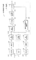
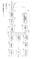
図1は、第1の実施の形態に係る計測装置(生体情報計測装置1)の一構成例を表すものである。生体情報計測装置1は、例えば生体9の血流を計測するものである。なお、本開示の実施の形態に係る計測方法は、本実施の形態により具現化されるので、併せて説明する。生体情報計測装置1は、光源11と、受光部12A,12Bと、増幅部13A,13Bと、AD変換部14A,14Bと、処理部20とを備えている。
<1. First Embodiment>
[Configuration example]
FIG. 1 illustrates a configuration example of a measurement apparatus (biological information measurement apparatus 1) according to the first embodiment. The biological
光源11は、例えば半導体レーザを用いて構成されるものであり、処理部20から供給された制御信号に基づいてコヒーレント光L1を出射するものである。光源11は、例えば、垂直共振器面発光レーザ(VCSEL;Vertical Cavity Surface Emitting Laser)を用いることができる。コヒーレント光L1の波長は、例えば、850nmにすることができる。
The
受光部12A,12Bは、例えばフォトダイオードを用いて構成されるものであり、光L2A,L2Bをそれぞれ受光し、受光量に応じた電気信号をそれぞれ出力するものである。
The
図2は、光源11及び受光部12A,12Bの配置を表すものである。この例では、受光部12A,12Bは、生体情報計測装置1の検出面1Sの面内において、光源11を挟むように配置されている。この構成により、光源11から出射し生体9に照射されたコヒーレント光L1のうちの一部が、例えば、血液中のヘモグロビンにより吸収され、一部が、生体9の内部における細胞膜、小器官などにより散乱される。そして、散乱された光のうちの一部が後方散乱光として生体9の外部に放出され、受光部12A,12Bにより受光される。その際、例えば、静止している細胞により散乱された光の波長は、コヒーレント光L1の波長と同じであるが、血液(特に赤血球)により散乱された光の波長は、血液の流れに応じて、トップラー現象により、コヒーレント光L1の波長から変化(ドップラーシフト)する。よって、受光部12A,12Bは、コヒーレント光L1の波長と同じ波長の光と、コヒーレント光L1の波長と異なる波長の光とを受光する。その結果、受光部12A,12Bが出力する電気信号には、脈拍に応じた、数Hz程度の周波数を有する交流成分に加え、血流速度に応じた、例えば数kHz〜10kHz程度の周波数を有する交流成分(ビート信号)が現れるようになっている。すなわち、このビート信号の周波数は、ドップラーシフトに対応するものである。
FIG. 2 shows the arrangement of the
なお、この図では、生体情報計測装置1の検出面1Sが生体9に接触しないようにしているが、これに限定されるものではなく、これに代えて、検出面1Sを生体9に接触させてもよい。
In this figure, the detection surface 1S of the biological
増幅部13Aは、受光部12Aから出力された電気信号を増幅するものである。増幅部13Bは、受光部12Bから出力された電気信号を増幅するものである。
The amplifying
AD変換部14Aは、増幅部13Aにより増幅された電気信号(アナログ信号)をAD変換することにより信号S14A(デジタル信号)を生成するものである。AD変換部14Bは、増幅部13Bにより増幅された電気信号(アナログ信号)をAD変換することにより信号S14B(デジタル信号)を生成するものである。AD変換部14A,14Bは、例えば、20kHz〜50kHz程度のサンプリング周波数で動作するようになっている。
The
これらの信号S14A,S14Bは、上述したように、脈拍に応じた、数Hz程度の周波数を有する交流成分と、血流速度に応じた、例えば数kHz〜10kHz程度の周波数を有する交流成分とを含んでいる。このうち、脈拍に応じた交流成分は、血管の容積の変化を示す、いわゆる容積脈波に対応するものである。すなわち、生体情報計測装置1は、血中のヘモグロビンが光を吸収する性質を利用して、いわゆる光電容積脈波(PPG;Photoplethysmography)方式を用いて、血管の容積の変化を計測している。また、血流速度に応じた交流成分は、ドップラーシフトにより生じたものであり、生体情報計測装置1は、この成分に基づいて血流量を求めることができる。
As described above, these signals S14A and S14B include an AC component having a frequency of about several Hz corresponding to the pulse and an AC component having a frequency of about several kHz to 10 kHz, for example, corresponding to the blood flow velocity. Contains. Among these, the AC component corresponding to the pulse corresponds to a so-called volume pulse wave indicating a change in the volume of the blood vessel. That is, the biological
処理部20は、信号S14A,S14Bに基づいて血流量PPを求め、求めた血流量PPを信号Soutとして出力するものである。処理部20は、例えば、ハードウェアにより構成してもよいし、プログラムを実行可能なプロセッサを用いて構成してもよい。処理部20は、光量制御部21と、差分演算部22と、フィルタ部23と、血流量演算部24と、容積脈波変動率演算部25と、補正部26とを有している。
The processing unit 20 obtains the blood flow rate PP based on the signals S14A and S14B, and outputs the obtained blood flow rate PP as a signal Sout. The processing unit 20 may be configured by hardware, for example, or may be configured by using a processor that can execute a program. The processing unit 20 includes a light
光量制御部21は、信号S14Bに基づいて、光源11が出射するコヒーレント光L1の光量を制御するものである。具体的には、光量制御部21は、信号S14Bに基づいて、増幅部13A,13BおよびAD変換部14A,14Bに適切な信号が入力されるように、コヒーレント光L1の光量を制御する。すなわち、例えば、コヒーレント光L1の光量が多い場合には、増幅部13A,13BおよびAD変換部14A,14Bの動作範囲を超えた信号が入力されてしまうおそれがある。また、例えば、コヒーレント光L1の光量が少ない場合には、光L2Bの光量が少ないため、増幅部13A,13BおよびAD変換部14A,14Bへの入力信号が小さくなりすぎてしまうおそれがある。光量制御部21は、信号S14Bに基づいて、コヒーレント光L1の光量を制御する。これにより、生体情報計測装置1では、増幅部13A,13BおよびAD変換部14A,14Bに適切な信号が入力されるようになっている。
The light
差分演算部22は、信号S14Aと信号S14Bとの差分を求め、その差分を信号S22として出力するものである。信号S22は、血流速度に応じた、例えば数kHz〜10kHz程度の周波数を有する交流成分を含む血流速度信号である。
The
フィルタ部23は、例えばFIR(Finite Impulse Response)フィルタを用いて構成されるものであり、信号S22に含まれる低周波成分を除去することにより信号S23を生成するハイパスフィルタである。具体的には、フィルタ部23は、例えば、100Hz以下の信号成分を除去する。これにより、フィルタ部23は、例えば、信号S22に含まれる、脈拍に応じた交流成分や、呼吸などの体の動きによるノイズ成分を除去するようになっている。
The
血流量演算部24は、信号S23に基づいてFFT(Fast Fourier Transform)解析を行うことにより、血流量Pを求めるものである。具体的には、血流量演算部24は、信号S23の波形を、例えば、数msec.の時間長を有する期間ごとに区切り、各期間においてFFT解析を行う。そして、血流量演算部24は、そのFFT解析結果に基づいて、以下の式を用いて、血流量Pを求める。
容積脈波変動率演算部25は、信号S14Bに基づいて、容積脈波変動率Qを求めるものである。具体的には、容積脈波変動率演算部25は、信号S14Bの波形を、例えば、数msec.の時間長を有する期間ごとに区切り、各期間において、信号S14Bの平均値および振幅値を求める。そして、容積脈波変動率演算部25は、振幅値を平均値で割ることにより、容積脈波変動率Qを求める。容積脈波変動率演算部25は、このようにして、数msec.ごとに容積脈波変動率Qを求める。そして、容積脈波変動率演算部25は、求めた容積脈波変動率Qを、順次、信号S25を用いて補正部26に供給するようになっている。
The volume pulse wave fluctuation
補正部26は、信号S25に含まれる容積脈波変動率Qに基づいて、信号SPに含まれる血流量Pを補正することにより、血流量PPを求めるものである。そして、補正部26は、この血流量PPを、信号Soutとして出力するようになっている。
The
ここで、受光部12A,12Bは、本開示における「第1の受光部」および「第2の受光部」の一具体例に対応する。AD変換部14A,14Bは、本開示における「第1の変換部」および「第2の変換部」の一具体例に対応する。血流量演算部24は、本開示における「解析部」の一具体例に対応する。
Here, the
[動作および作用]
続いて、本実施の形態の生体情報計測装置1の動作および作用について説明する。
[Operation and Action]
Then, operation | movement and an effect | action of the biological
(全体動作概要)
まず、図1を参照して、生体情報計測装置1の全体動作概要を説明する。光源11は、処理部20から供給された制御信号に基づいてコヒーレント光L1を出射する。生体9に照射されたコヒーレント光L1は、生体9の内部において一部が吸収されるとともに一部が散乱され、散乱された光のうちの一部が後方散乱光として生体9の外部に放出される。受光部12Aは、生体9から放出された光L2Aを受光し、受光量に応じた電気信号を出力する。増幅部13Aは、受光部12Aから出力された電気信号を増幅する。AD変換部14Aは、増幅部13Aにより増幅された電気信号(アナログ信号)をAD変換することにより信号S14A(デジタル信号)を生成する。同様に、受光部12Bは、生体9から放出された光L2Bを受光し、受光量に応じた電気信号を出力する。増幅部13Bは、受光部12Bから出力された電気信号を増幅する。AD変換部14Bは、増幅部13Bにより増幅された電気信号(アナログ信号)をAD変換することにより信号S14B(デジタル信号)を生成する。
(Overview of overall operation)
First, with reference to FIG. 1, an overall operation overview of the biological
処理部20において、光量制御部21は、信号S14Bに基づいて、光源11が出射するコヒーレント光L1の光量を制御する。差分演算部22は、信号S14Aと信号S14Bとの差分を求め、その差分を信号S22として出力する。フィルタ部23は、信号S22に含まれる低周波成分を除去することにより信号S23を生成する。血流量演算部24は、信号S23に基づいてFFT解析を行うことにより、血流量Pを求め、求めた血流量Pを、順次、信号S24を用いて補正部26に供給する。容積脈波変動率演算部25は、信号S14Bに基づいて、容積脈波変動率Qを求め、求めた容積脈波変動率Qを、順次、信号S25を用いて補正部26に供給する。補正部26は、信号S25に含まれる容積脈波変動率Qに基づいて、信号SPに含まれる血流量Pを補正することにより、血流量PPを求める。
In the processing unit 20, the light
(詳細動作)
次に、生体情報計測装置1の詳細動作について説明する。光源11から出射し生体9に照射されたコヒーレント光L1は、生体9の内部において一部が吸収されるとともに一部が散乱され、散乱された光のうちの一部が後方散乱光として生体9の外部に放出され、受光部12A,12Bにより受光される。その際、例えば、静止している細胞により散乱された光の波長は、コヒーレント光L1の波長と同じであるが、血液(特に赤血球)により散乱された光の波長は、血液の流れに応じて、トップラー現象により、コヒーレント光L1の波長から変化(ドップラーシフト)する。よって、受光部12A,12Bは、コヒーレント光L1の波長と同じ波長の光と、コヒーレント光L1の波長と異なる波長の光とを受光する。その結果、受光部12A,12Bが出力する電気信号には、脈拍に応じた、数Hz程度の周波数を有する交流成分に加え、血流速度に応じた、例えば数kHz〜10kHz程度の周波数を有する交流成分(ビート信号)が現れる。
(Detailed operation)
Next, the detailed operation of the biological
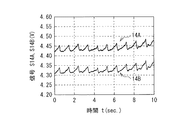
図3は、受光部12Aに係るAD変換部14Aの出力信号S14Aの波形、および受光部12Bに係るAD変換部14Bの出力信号S14Bの波形の一例を表すものである。図3に示したように、信号S14A,S14Bは、脈拍に応じた、数Hz程度の周波数を有する交流成分を含んでいる。また、この信号S14A,S14Bは、例えば数kHz〜10kHz程度の周波数を有する交流成分(ビート信号)を含んでいる。
FIG. 3 shows an example of the waveform of the output signal S14A of the
差分演算部22は、信号S14Aと信号S14Bとの差分を求め、その差分を信号S22として出力する。フィルタ部23は、信号S22に含まれる高周波成分を除去することにより信号S23を生成する。そして、血流量演算部24は、信号S23に基づいてFFT解析を行うことにより、血流量Pを求める。具体的には、血流量演算部24は、信号S23の波形を、例えば、数msec.の時間長を有する期間ごとに区切り、各期間においてFFT解析を行う。そして、血流量演算部24は、そのFFT解析結果に基づいて、式(EQ1)を用いて、血流量Pを求める。
The
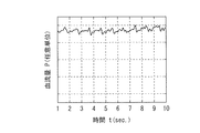
図4は、血流量Pの一例を表すものである。血流量演算部24は、この例では数msec.ごとに血流量Pを求める。そして、血流量演算部24は、求めた血流量Pを、順次、信号S24を用いて補正部26に供給する。
FIG. 4 shows an example of the blood flow rate P. In this example, the blood flow
ところで、生体情報計測装置1では、血流量Pを測定する際、例えば、生体情報計測装置1の検出面1Sを生体9に接触させる。このとき、血流量Pが、接触圧により変化してしまうおそれがある。そこで、生体情報計測装置1では、容積脈波変動率Qも血流量Pと同様に接触圧により変化することを利用し、血流量Pを補正する。
By the way, in the biological
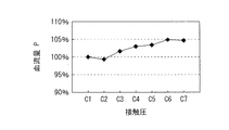
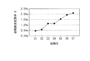
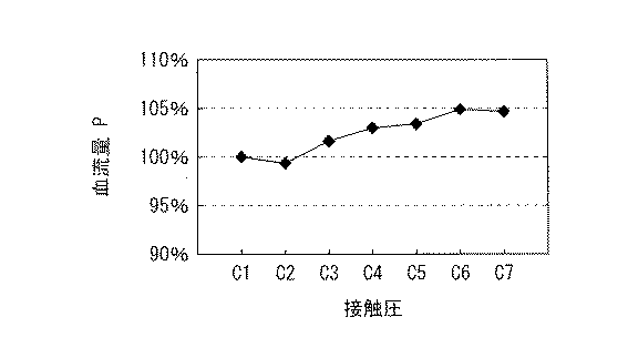
図5は、接触圧を変化させたときに計測される血流量Pの一例を表すものである。図6は、接触圧を変化させたときに計測される容積脈波変動率Qの一例を表すものである。図5,6は、接触圧C1〜C7のそれぞれにおける血流量Pおよび容積脈波変動率Qを示している。ここで、接触圧C1〜C7のうち、接触圧C1が一番低く、接触圧C7が一番高い。血流量Pは、接触圧C1における血流量を100%として規格化している。この例では、血流量Pは、接触圧が高くなるほど多くなり、同様に、容積脈波変動率Qは、接触圧が高くなるほど大きくなる。 FIG. 5 shows an example of the blood flow rate P measured when the contact pressure is changed. FIG. 6 shows an example of the volume pulse wave fluctuation rate Q measured when the contact pressure is changed. 5 and 6 show the blood flow rate P and the volume pulse wave fluctuation rate Q at each of the contact pressures C1 to C7. Here, among the contact pressures C1 to C7, the contact pressure C1 is the lowest and the contact pressure C7 is the highest. The blood flow rate P is normalized with the blood flow rate at the contact pressure C1 as 100%. In this example, the blood flow rate P increases as the contact pressure increases, and similarly, the volume pulse wave fluctuation rate Q increases as the contact pressure increases.
このように、血管の容積の変化に対応する容積脈波と、血流とは、互いに独立した現象であるが、ともに接触圧と相関がある。補正部26は、このように、血流量Pおよび容積脈波変動率Qの接触圧依存性を利用し、次式を用いて、血流量Pを補正する。
なお、この例では、式(EQ2)に示したように、接触圧の影響が、容積脈波変動率Qのk乗に比例するものとしたが、これに限定されるものではなく、これに代えて、他の式を用いてもよい。 In this example, as shown in the equation (EQ2), the influence of the contact pressure is proportional to the kth power of the volume pulse wave fluctuation rate Q, but the present invention is not limited to this. Instead, other formulas may be used.
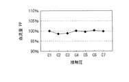
図7は、補正後の血流量PPの一例を表すものである。このように、補正後の血流量PPは、補正前の血流量P(図5)と比べて、接触圧を変化させたときの変化量が小さくなっている。 FIG. 7 shows an example of the corrected blood flow rate PP. As described above, the corrected blood flow rate PP is smaller than the blood flow rate P before correction (FIG. 5) when the contact pressure is changed.
このように、生体情報計測装置1では、信号S14Aおよび信号S14Bの差分(血流速度信号)と、信号S14Bに含まれる容積脈波信号とに基づいて、血流量PPを求めるようにした。言い換えれば、生体情報計測装置1では、信号S14Bに含まれる容積脈波の情報を用いて、血流量Pを補正するようにした。これにより、生体情報計測装置1では、この例では、接触圧の影響を抑えることができ、計測精度を高めることができる。
As described above, in the biological
[効果]
以上のように本実施の形態では、信号S14Aおよび信号S14Bの差分(血流速度信号)と、信号S14Bに含まれる容積脈波信号とに基づいて、血流量PPを求めるようにしたので、計測精度を高めることができる。
[effect]
As described above, in the present embodiment, the blood flow rate PP is obtained based on the difference between the signal S14A and the signal S14B (blood flow velocity signal) and the volume pulse wave signal included in the signal S14B. Accuracy can be increased.
[変形例1−1]
上記実施の形態では、信号S14Bに基づいて容積脈波変動率Qを求めたが、これに限定されるものではない。これに代えて、例えば、信号S14Aに基づいて容積脈波変動率Qを求めてもよい。また、図8に示す生体情報計測装置1Aのように、信号S14A,S14Bの平均値に基づいて容積脈波変動率Qを求めてもよい。この生体情報計測装置1Aは、処理部20Aを備えている。処理部20Aは、平均演算部27Aを有している。平均演算部27Aは、信号S14Aと信号S14Bの平均値を求めるものである。そして、容積脈波変動率演算部25は、平均演算部27Aの演算結果に基づいて容積脈波変動率Qを求めるようになっている。なお、これに限定されるものではなく、これに代えて、信号S14A,S14Bの和に基づいて容積脈波変動率Qを求めてもよい。
[Modification 1-1]
In the above embodiment, the volume pulse wave fluctuation rate Q is obtained based on the signal S14B, but the present invention is not limited to this. Instead of this, for example, the volume pulse wave fluctuation rate Q may be obtained based on the signal S14A. Further, as in the biological information measuring apparatus 1A shown in FIG. 8, the volume pulse wave variation rate Q may be obtained based on the average value of the signals S14A and S14B. This biological information measuring apparatus 1A includes a processing unit 20A. The processing unit 20A includes an
[変形例1−2]
上記実施の形態では、光量制御部21は、信号S14Bに基づいて、光源11が出射するコヒーレント光L1の光量を制御したが、これに限定されるものではない。これに代えて、例えば、信号S14Aに基づいて、コヒーレント光L1の光量を制御してもよい。また、図8に示した生体情報計測装置1Aと同様に、信号S14A,S14Bの平均値に基づいて、コヒーレント光L1の光量を制御してもよいし、信号S14A,S14Bの和に基づいて、コヒーレント光L1の光量を制御してもよい。
[Modification 1-2]
In the above embodiment, the light
<2.第2の実施の形態>
次に、第2の実施の形態に係る生体情報計測装置2について説明する。本実施の形態に係る生体情報計測装置2は、生体9の心拍数を計測するものである。なお、上記第1の実施の形態に係る生体情報計測装置1と実質的に同一の構成部分には同一の符号を付し、適宜説明を省略する。
<2. Second Embodiment>
Next, the biological
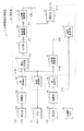
生体情報計測装置2は、加速度センサ19と、処理部30とを備えている。加速度センサ19は、生体情報計測装置2を装着した生体9の動きを検出し、その検出結果を信号S19として出力するものである。処理部30は、信号S14A,S14B、および信号S19に基づいて心拍数HRを求め、求めた心拍数HRを信号Soutとして出力するものである。
The biological
処理部30は、心拍数演算部35,36と、選択制御部37と、選択部38とを有している。心拍数演算部35は、血流量演算部24により求められた血流量P(例えば図4)に基づいて、心拍数HR1を求め、信号S35として出力するものである。心拍数演算部36は、信号S14B(例えば図3)に基づいて、心拍数HR2を求め、信号S36として出力するものである。選択制御部37は、信号S19を用いて供給された生体9の動きを示す情報に基づいて、選択部38が、信号S35,S36のうちのどちらを選択すべきかを判断し、その判断結果に基づいて選択部38の動作を制御するものである。具体的には、選択制御部37は、生体9の動きの周波数が所定の周波数(例えば1Hz)に近い場合には、信号S35を選択し、生体9の動きの周波数が所定の周波数(例えば1Hz)から離れている場合には、信号S36を選択するように、選択部38の動作を制御するようになっている。選択部38は、選択制御部37からの制御信号に基づいて、信号S35,S36のうちの一方を選択し、選択された信号を信号Soutとして出力するものである。
The processing unit 30 includes heart
ここで、心拍数演算部35は、本開示における「第1の演算部」の一具体例に対応する。心拍数演算部36は、本開示における「第2の演算部」の一具体例に対応する。
Here, the heart
この構成により、生体情報計測装置2では、生体9の動きの周波数が所定の周波数(例えば1Hz)に近い場合には、血流量P(例えば図4)に基づいて得られた心拍数HR1を選択し、生体9の動きの周波数が所定の周波数(例えば1Hz)から離れている場合には、容積脈波(例えば図3)に基づいて得られた心拍数HR2を選択する。これにより、生体情報計測装置2では、計測精度を高めることができるとともに、消費電力を抑えることができる。
With this configuration, the biological
すなわち、まず、例えば、人間がこのような生体情報計測装置2を腕に装着して走った場合に、その腕の振りに対応する周波数(運動周波数)が心拍の周波数(例えば1Hz)に近くなる場合が有り得る。例えば、容積脈波を利用して心拍数を求める場合には、このように運動周波数が心拍の周波数に近づくと、腕の振りに起因するノイズ成分を除去できなくなるおそれがある。このような場合には、心拍数の計測精度が低下してしまう。一方、血流量Pを利用して心拍数を求める場合には、運動周波数が心拍の周波数(例えば1Hz)に近づいても、運動周波数が血流速度信号の周波数成分(例えば数kHz〜10kHz程度)と異なるため、腕の振りに起因するノイズ成分を効果的に除去することができる。よって、このような場合には、血流量Pを利用して心拍数を求めることにより、心拍数の計測精度を高めることができる。
That is, first, for example, when a human runs with such a biological
また、運動周波数が心拍の周波数(例えば1Hz)から離れている場合には、容積脈波を利用して心拍数を求めても、あるいは、血流量Pを利用して心拍数を求めても、高い計測精度で心拍数を計測することができる。よって、このような場合には、容積脈波を利用して心拍数を求めるとともに、例えば、差分演算部22、フィルタ部23、血流量演算部24、および心拍数演算部35の動作を停止させることにより、消費電力を低減することができる。また、さらに、AD変換部14A,14Bのサンプリング周波数を下げることにより、さらに消費電力を低減することができる。
Further, when the motion frequency is far from the heartbeat frequency (for example, 1 Hz), even if the heart rate is obtained using the volume pulse wave, or the heart rate is obtained using the blood flow rate P, Heart rate can be measured with high measurement accuracy. Therefore, in such a case, the heart rate is obtained using the volume pulse wave, and for example, the operations of the
以上のように本実施の形態では、信号S14Aおよび信号S14Bの差分(血流速度信号)と、信号S14Bに含まれる容積脈波信号とに基づいて、心拍数を求めるようにしたので、計測精度を高めることができる。 As described above, in the present embodiment, the heart rate is obtained based on the difference between the signals S14A and S14B (blood flow velocity signal) and the volume pulse wave signal included in the signal S14B. Can be increased.
本実施の形態では、生体の動きの周波数に応じて、血流量に基づいて得られた心拍数、および容積脈波に基づいて得られた心拍数のうちの一方を選択するようにしたので、計測精度を高めることができるとともに、消費電力を抑えることができる。 In the present embodiment, since one of the heart rate obtained based on the blood flow rate and the heart rate obtained based on the volume pulse wave is selected according to the frequency of the movement of the living body, Measurement accuracy can be increased and power consumption can be reduced.
[変形例2−1]
上記実施の形態に係る生体情報計測装置2に、上記第1の実施の形態の各変形例を適用してもよい。
[Modification 2-1]
You may apply each modification of the said 1st Embodiment to the biological
<3.適用例>
次に、上記実施の形態および変形例で説明した生体情報計測装置の適用例について説明する。
<3. Application example>
Next, an application example of the biological information measuring device described in the above embodiment and modifications will be described.
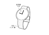
図10は、上記実施の形態等の生体情報計測装置が適用される腕時計の外観を表すものである。この腕時計は、例えば、文字盤110と、バンド部120とを有している。この文字盤110の裏側の、ユーザの腕と接触する面には、上記実施の形態等に係る生体情報計測装置が搭載されている。
FIG. 10 shows the appearance of a wristwatch to which the biological information measuring apparatus according to the above-described embodiment or the like is applied. This wristwatch has, for example, a
上記実施の形態等の生体情報計測装置は、このような腕時計の他、リストバンド、指輪など、ユーザが身につける様々なものに適用することが可能であり、これにより、生体情報を計測可能なウェアラブル端末を構成することができる。 The biological information measuring apparatus according to the above-described embodiment can be applied to various things worn by the user such as wristbands, rings, etc. in addition to such wristwatches, and thereby it is possible to measure biological information A simple wearable terminal can be configured.
以上、いくつかの実施の形態および変形例、ならびに電子機器への適用例を挙げて本技術を説明したが、本技術はこれらの実施の形態等には限定されず、種々の変形が可能である。 The present technology has been described above with some embodiments and modifications, and application examples to electronic devices. However, the present technology is not limited to these embodiments and the like, and various modifications are possible. is there.
例えば、上記の各実施の形態では、本技術を生体情報計測装置に適用したが、これに限定されるものではなく、生体情報以外の情報を計測する装置に適用してもよい。具体的には、例えば、液体の流量を計測する装置に適用することができる。 For example, in each of the above-described embodiments, the present technology is applied to the biological information measuring device. However, the present technology is not limited to this, and may be applied to a device that measures information other than biological information. Specifically, for example, the present invention can be applied to an apparatus for measuring a liquid flow rate.
なお、本明細書に記載された効果はあくまで例示であって限定されるものでは無く、また他の効果があってもよい。 In addition, the effect described in this specification is an illustration to the last, and is not limited, Moreover, there may exist another effect.
なお、本技術は以下のような構成とすることができる。 In addition, this technique can be set as the following structures.
(1)コヒーレント光を出射する光源と、
第1の受光部および第2の受光部と、
前記第1の受光部による受光結果をAD変換することにより第1の信号を生成する第1の変換部と、
前記第2の受光部による受光結果をAD変換することにより第2の信号を生成する第2の変換部と、
前記第1の信号および前記第2の信号に基づいて、所定の処理を行う処理部と
を備えた計測装置。
(2)前記処理部は、前記第1の信号および前記第2の信号の差分と、前記第1の信号および前記第2の信号の一方または双方における交流成分とに基づいて、前記所定の処理を行う
前記(1)に記載の計測装置。
(3)前記処理部は、さらに、前記第1の信号および前記第2の信号の一方または双方に基づいて、前記コヒーレント光の強度を調節する
前記(1)または(2)に記載の計測装置。
(4)前記処理部は、
前記第1の信号および前記第2の信号の差分を求める差分演算部と、
前記差分に基づいて周波数解析を行う解析部と
を有する
前記(1)から(3)のいずれかに記載の計測装置。
(5)前記処理部は、前記第1の信号および前記第2の信号の一方または双方における交流成分に基づいて、前記解析部による解析結果を補正する補正部をさらに有する
前記(4)に記載の計測装置。
(6)前記光源は生体に対して前記コヒーレント光を出射し、
前記第1の受光部および前記第2の受光部は、前記生体からの光をそれぞれ受光し、
前記第1の信号および前記第2の信号のそれぞれは、前記生体の容積脈波情報および前記生体の血流速度情報を含み、
前記解析部は、前記周波数解析により前記生体の血流量を求める
前記(4)または(5)に記載の計測装置。
(7)前記処理部は、
前記解析部における解析結果に基づいて第3の信号を生成する第1の演算部と、
前記第1の信号および前記第2の信号の一方または双方における交流成分に基づいて第4の信号を生成する第2の演算部と、
前記第3の信号または前記第4の信号を選択する選択部と
を有する
前記(4)に記載の計測装置。
(8)加速度センサをさらに備え、
前記選択部は、前記加速度センサの検出結果に基づいて、前記第3の信号および前記第4の信号のうちの一方を選択する
前記(7)に記載の計測装置。
(9)前記光源は生体に対して前記コヒーレント光を出射し、
前記第1の受光部および前記第2の受光部は、前記生体からの光をそれぞれ受光し、
前記第1の信号および前記第2の信号のそれぞれは、前記生体の容積脈波情報および前記生体の血流速度情報を含み、
前記解析部は、前記周波数解析により前記生体の血流量を求め、
前記第3の信号および前記第4の信号は、前記生体の心拍数情報を含む
前記(7)または(8)に記載の計測装置。
(10)前記処理部は、前記差分に対してフィルタ処理を行うフィルタ部を有し、
前記解析部は、前記フィルタ部による処理結果に基づいて前記周波数解析を行う
前記(4)から(9)のいずれかに記載の計測装置。
(11)前記第1の受光部および前記第2の受光部は、前記光源を挟むように配置された
前記(1)から(10)のいずれかに記載の計測装置。
(12)コヒーレント光を出射し、
前記コヒーレント光に基づく第1の光を受光するとともに、前記コヒーレント光に基づく第2の光を受光し、
前記第1の光の受光結果をAD変換することにより第1の信号を生成するとともに、前記第2の光の受光結果をAD変換することにより第2の信号を生成し、
前記第1の信号および前記第2の信号に基づいて、所定の処理を行う
計測方法。
(13)コヒーレント光を出射する光源と、
第1の受光部および第2の受光部と、
前記第1の受光部による受光結果をAD変換することにより第1の信号を生成する第1の変換部と、
前記第2の受光部による受光結果をAD変換することにより第2の信号を生成する第2の変換部と、
前記第1の信号および前記第2の信号に基づいて、所定の処理を行う処理部と
を備えた電子機器。
(1) a light source that emits coherent light;
A first light receiving part and a second light receiving part;
A first conversion unit that generates a first signal by performing AD conversion on a light reception result of the first light receiving unit;
A second conversion unit that generates a second signal by performing AD conversion on a light reception result of the second light receiving unit;
And a processing unit that performs a predetermined process based on the first signal and the second signal.
(2) The processing unit performs the predetermined processing based on a difference between the first signal and the second signal and an AC component in one or both of the first signal and the second signal. The measuring device according to (1) above.
(3) The measurement unit according to (1) or (2), wherein the processing unit further adjusts the intensity of the coherent light based on one or both of the first signal and the second signal. .
(4) The processing unit includes:
A difference calculation unit for obtaining a difference between the first signal and the second signal;
The measurement device according to any one of (1) to (3), further including: an analysis unit that performs frequency analysis based on the difference.
(5) The processing unit further includes a correction unit that corrects an analysis result by the analysis unit based on an AC component in one or both of the first signal and the second signal. Measuring device.
(6) The light source emits the coherent light to a living body,
Each of the first light receiving unit and the second light receiving unit receives light from the living body,
Each of the first signal and the second signal includes volume pulse wave information of the living body and blood flow velocity information of the living body,
The measurement unit according to (4) or (5), wherein the analysis unit obtains a blood flow rate of the living body by the frequency analysis.
(7) The processing unit includes:
A first calculation unit that generates a third signal based on an analysis result in the analysis unit;
A second arithmetic unit that generates a fourth signal based on an alternating current component in one or both of the first signal and the second signal;
The measurement apparatus according to (4), further including a selection unit that selects the third signal or the fourth signal.
(8) further comprising an acceleration sensor;
The measurement device according to (7), wherein the selection unit selects one of the third signal and the fourth signal based on a detection result of the acceleration sensor.
(9) The light source emits the coherent light to a living body,
Each of the first light receiving unit and the second light receiving unit receives light from the living body,
Each of the first signal and the second signal includes volume pulse wave information of the living body and blood flow velocity information of the living body,
The analysis unit obtains the blood flow volume of the living body by the frequency analysis,
The measurement device according to (7) or (8), wherein the third signal and the fourth signal include heart rate information of the living body.
(10) The processing unit includes a filter unit that performs a filtering process on the difference,
The measurement device according to any one of (4) to (9), wherein the analysis unit performs the frequency analysis based on a processing result by the filter unit.
(11) The measuring device according to any one of (1) to (10), wherein the first light receiving unit and the second light receiving unit are disposed so as to sandwich the light source.
(12) emit coherent light,
Receiving the first light based on the coherent light and receiving the second light based on the coherent light;
A first signal is generated by AD converting the light reception result of the first light, and a second signal is generated by AD converting the light reception result of the second light,
A measurement method that performs predetermined processing based on the first signal and the second signal.
(13) a light source that emits coherent light;
A first light receiving part and a second light receiving part;
A first conversion unit that generates a first signal by performing AD conversion on a light reception result of the first light receiving unit;
A second conversion unit that generates a second signal by performing AD conversion on a light reception result of the second light receiving unit;
An electronic apparatus comprising: a processing unit that performs predetermined processing based on the first signal and the second signal.
1,1A,2…生体情報計測装置、1S…検出面、11…光源、12A,12B…受光部、13A,13B…増幅部、14A,14B…AD変換部、19…加速度センサ、20,20A,30…処理部、21…光量制御部、22…差分演算部、23…フィルタ部、24…血流量演算部、25…容積脈波変動率演算部、26…補正部、27A…平均演算部、35,36…心拍数演算部、37…選択制御部、38…選択部、C1〜C7…接触圧、L1…コヒーレント光、L2A,L2B…光、P,PP…血流量、Q…容積脈波変動率、S14A,S14B,S22,S23,S24,S25,Sout…信号。
DESCRIPTION OF
Claims (13)
第1の受光部および第2の受光部と、
前記第1の受光部による受光結果をAD変換することにより第1の信号を生成する第1の変換部と、
前記第2の受光部による受光結果をAD変換することにより第2の信号を生成する第2の変換部と、
前記第1の信号および前記第2の信号に基づいて、所定の処理を行う処理部と
を備えた計測装置。 A light source that emits coherent light;
A first light receiving part and a second light receiving part;
A first conversion unit that generates a first signal by performing AD conversion on a light reception result of the first light receiving unit;
A second conversion unit that generates a second signal by performing AD conversion on a light reception result of the second light receiving unit;
And a processing unit that performs a predetermined process based on the first signal and the second signal.
請求項1に記載の計測装置。 The processing unit performs the predetermined processing based on a difference between the first signal and the second signal and an AC component in one or both of the first signal and the second signal. Item 2. The measuring device according to Item 1.
請求項1に記載の計測装置。 The measurement device according to claim 1, wherein the processing unit further adjusts the intensity of the coherent light based on one or both of the first signal and the second signal.
前記第1の信号および前記第2の信号の差分を求める差分演算部と、
前記差分に基づいて周波数解析を行う解析部と
を有する
請求項1に記載の計測装置。 The processor is
A difference calculation unit for obtaining a difference between the first signal and the second signal;
The measurement device according to claim 1, further comprising: an analysis unit that performs frequency analysis based on the difference.
請求項4に記載の計測装置。 The measurement apparatus according to claim 4, wherein the processing unit further includes a correction unit that corrects an analysis result by the analysis unit based on an AC component in one or both of the first signal and the second signal.
前記第1の受光部および前記第2の受光部は、前記生体からの光をそれぞれ受光し、
前記第1の信号および前記第2の信号のそれぞれは、前記生体の容積脈波情報および前記生体の血流速度情報を含み、
前記解析部は、前記周波数解析により前記生体の血流量を求める
請求項4に記載の計測装置。 The light source emits the coherent light to a living body,
Each of the first light receiving unit and the second light receiving unit receives light from the living body,
Each of the first signal and the second signal includes volume pulse wave information of the living body and blood flow velocity information of the living body,
The measurement device according to claim 4, wherein the analysis unit obtains a blood flow rate of the living body by the frequency analysis.
前記解析部における解析結果に基づいて第3の信号を生成する第1の演算部と、
前記第1の信号および前記第2の信号の一方または双方における交流成分に基づいて第4の信号を生成する第2の演算部と、
前記第3の信号または前記第4の信号を選択する選択部と
を有する
請求項4に記載の計測装置。 The processor is
A first calculation unit that generates a third signal based on an analysis result in the analysis unit;
A second arithmetic unit that generates a fourth signal based on an alternating current component in one or both of the first signal and the second signal;
The measurement apparatus according to claim 4, further comprising: a selection unit that selects the third signal or the fourth signal.
前記選択部は、前記加速度センサの検出結果に基づいて、前記第3の信号および前記第4の信号のうちの一方を選択する
請求項7に記載の計測装置。 An acceleration sensor,
The measurement device according to claim 7, wherein the selection unit selects one of the third signal and the fourth signal based on a detection result of the acceleration sensor.
前記第1の受光部および前記第2の受光部は、前記生体からの光をそれぞれ受光し、
前記第1の信号および前記第2の信号のそれぞれは、前記生体の容積脈波情報および前記生体の血流速度情報を含み、
前記解析部は、前記周波数解析により前記生体の血流量を求め、
前記第3の信号および前記第4の信号は、前記生体の心拍数情報を含む
請求項7に記載の計測装置。 The light source emits the coherent light to a living body,
Each of the first light receiving unit and the second light receiving unit receives light from the living body,
Each of the first signal and the second signal includes volume pulse wave information of the living body and blood flow velocity information of the living body,
The analysis unit obtains the blood flow volume of the living body by the frequency analysis,
The measurement apparatus according to claim 7, wherein the third signal and the fourth signal include heart rate information of the living body.
前記解析部は、前記フィルタ部による処理結果に基づいて前記周波数解析を行う
請求項4に記載の計測装置。 The processing unit includes a filter unit that performs a filtering process on the difference,
The measurement device according to claim 4, wherein the analysis unit performs the frequency analysis based on a processing result by the filter unit.
請求項1に記載の計測装置。 The measuring apparatus according to claim 1, wherein the first light receiving unit and the second light receiving unit are arranged so as to sandwich the light source.
前記コヒーレント光に基づく第1の光を受光するとともに、前記コヒーレント光に基づく第2の光を受光し、
前記第1の光の受光結果をAD変換することにより第1の信号を生成するとともに、前記第2の光の受光結果をAD変換することにより第2の信号を生成し、
前記第1の信号および前記第2の信号に基づいて、所定の処理を行う
計測方法。 Emit coherent light,
Receiving the first light based on the coherent light and receiving the second light based on the coherent light;
A first signal is generated by AD converting the light reception result of the first light, and a second signal is generated by AD converting the light reception result of the second light,
A measurement method that performs predetermined processing based on the first signal and the second signal.
第1の受光部および第2の受光部と、
前記第1の受光部による受光結果をAD変換することにより第1の信号を生成する第1の変換部と、
前記第2の受光部による受光結果をAD変換することにより第2の信号を生成する第2の変換部と、
前記第1の信号および前記第2の信号に基づいて、所定の処理を行う処理部と
を備えた電子機器。
A light source that emits coherent light;
A first light receiving part and a second light receiving part;
A first conversion unit that generates a first signal by performing AD conversion on a light reception result of the first light receiving unit;
A second conversion unit that generates a second signal by performing AD conversion on a light reception result of the second light receiving unit;
An electronic apparatus comprising: a processing unit that performs predetermined processing based on the first signal and the second signal.
Priority Applications (1)
| Application Number | Priority Date | Filing Date | Title |
|---|---|---|---|
| JP2016086042A JP2017192629A (en) | 2016-04-22 | 2016-04-22 | Measurement device, measurement method, and electronic apparatus |
Applications Claiming Priority (1)
| Application Number | Priority Date | Filing Date | Title |
|---|---|---|---|
| JP2016086042A JP2017192629A (en) | 2016-04-22 | 2016-04-22 | Measurement device, measurement method, and electronic apparatus |
Publications (1)
| Publication Number | Publication Date |
|---|---|
| JP2017192629A true JP2017192629A (en) | 2017-10-26 |
Family
ID=60155146
Family Applications (1)
| Application Number | Title | Priority Date | Filing Date |
|---|---|---|---|
| JP2016086042A Pending JP2017192629A (en) | 2016-04-22 | 2016-04-22 | Measurement device, measurement method, and electronic apparatus |
Country Status (1)
| Country | Link |
|---|---|
| JP (1) | JP2017192629A (en) |
Cited By (4)
| Publication number | Priority date | Publication date | Assignee | Title |
|---|---|---|---|---|
| WO2019208165A1 (en) | 2018-04-24 | 2019-10-31 | ソニー株式会社 | Scattered light signal measuring device, and information processing device |
| WO2020031646A1 (en) * | 2018-08-09 | 2020-02-13 | ソニー株式会社 | Biological information acquisition device, head-mounted information presentation device, and biological information acquisition method |
| WO2020179345A1 (en) * | 2019-03-01 | 2020-09-10 | ソニー株式会社 | Blood flow measurement device |
| WO2020255840A1 (en) | 2019-06-20 | 2020-12-24 | ソニー株式会社 | Information processing device, information processing method, and program |
-
2016
- 2016-04-22 JP JP2016086042A patent/JP2017192629A/en active Pending
Cited By (8)
| Publication number | Priority date | Publication date | Assignee | Title |
|---|---|---|---|---|
| WO2019208165A1 (en) | 2018-04-24 | 2019-10-31 | ソニー株式会社 | Scattered light signal measuring device, and information processing device |
| EP4357790A1 (en) | 2018-04-24 | 2024-04-24 | Sony Group Corporation | Scattered light signal measuring device, and information processing device |
| US12245846B2 (en) | 2018-04-24 | 2025-03-11 | Sony Corporation | Scattered light signal measuring apparatus and information processing apparatus |
| WO2020031646A1 (en) * | 2018-08-09 | 2020-02-13 | ソニー株式会社 | Biological information acquisition device, head-mounted information presentation device, and biological information acquisition method |
| CN112533531A (en) * | 2018-08-09 | 2021-03-19 | 索尼公司 | Biological information acquisition device, head-mounted information presentation device, and biological information acquisition method |
| CN112533531B (en) * | 2018-08-09 | 2023-12-15 | 索尼公司 | Biological information acquisition device, head-mounted information presentation device and biological information acquisition method |
| WO2020179345A1 (en) * | 2019-03-01 | 2020-09-10 | ソニー株式会社 | Blood flow measurement device |
| WO2020255840A1 (en) | 2019-06-20 | 2020-12-24 | ソニー株式会社 | Information processing device, information processing method, and program |
Similar Documents
| Publication | Publication Date | Title |
|---|---|---|
| CN104135917B (en) | Pulsometer | |
| CN103815888B (en) | Biological signal measuring device and biological signal measuring method | |
| JP5516428B2 (en) | Pulsation period calculation device and biological sensor provided with the same | |
| JP6126220B2 (en) | Biological state estimation device | |
| US9480407B2 (en) | Device and method for removal of ambient noise signal from a photoplethysmograph | |
| JP2007007075A (en) | Blood pressure measurement device | |
| KR20190072556A (en) | Acquisition of blood pressure signal using pressure sensor array | |
| EP3125753B1 (en) | Monitoring device and method for compensating non-linearity effects in vital signs monitoring | |
| JP2016123424A (en) | Blood pressure measurement system and blood circulation parameter determination method | |
| JP2018500949A (en) | Method and apparatus for measuring blood pressure using acoustic signals | |
| JP2017192629A (en) | Measurement device, measurement method, and electronic apparatus | |
| WO2020114989A1 (en) | System, method and computer program for measuring blood pressure | |
| WO2012073069A1 (en) | A method and system for pulse measurement | |
| JP5605253B2 (en) | Pulse wave measuring device and program | |
| CN110292372B (en) | Detection device | |
| JP2015107310A (en) | Blood pressure measurement apparatus and blood pressure measurement method | |
| EP2974651A1 (en) | Method for collecting personal health data and personal health device utilizing the same | |
| JP6115329B2 (en) | Biological information processing apparatus and biological information processing method | |
| WO2015115114A1 (en) | Blood pressure measurement system and pulse wave sensor | |
| JP2013183845A (en) | Pulsation detector, electronic device and program | |
| JP2013202077A (en) | Pulse meter and program | |
| JP2013172763A (en) | Pulsation detecting device, electronic apparatus, and program | |
| JP6160022B2 (en) | Pulse meter and program | |
| JP2012095795A (en) | Pulse wave analysis method | |
| JP2014188286A (en) | Pulsimeter and program |