JP2017192879A - Sludge exhaust piping device - Google Patents
Sludge exhaust piping device Download PDFInfo
- Publication number
- JP2017192879A JP2017192879A JP2016083365A JP2016083365A JP2017192879A JP 2017192879 A JP2017192879 A JP 2017192879A JP 2016083365 A JP2016083365 A JP 2016083365A JP 2016083365 A JP2016083365 A JP 2016083365A JP 2017192879 A JP2017192879 A JP 2017192879A
- Authority
- JP
- Japan
- Prior art keywords
- sludge
- hose
- piping
- pipe
- suction port
- Prior art date
- Legal status (The legal status is an assumption and is not a legal conclusion. Google has not performed a legal analysis and makes no representation as to the accuracy of the status listed.)
- Granted
Links
- 239000010802 sludge Substances 0.000 title claims abstract description 107
- XLYOFNOQVPJJNP-UHFFFAOYSA-N water Substances O XLYOFNOQVPJJNP-UHFFFAOYSA-N 0.000 claims abstract description 64
- 238000011144 upstream manufacturing Methods 0.000 description 16
- 238000000034 method Methods 0.000 description 5
- 238000007599 discharging Methods 0.000 description 4
- 239000000523 sample Substances 0.000 description 4
- 239000003245 coal Substances 0.000 description 3
- 239000008400 supply water Substances 0.000 description 3
- 239000002351 wastewater Substances 0.000 description 2
- 229910000975 Carbon steel Inorganic materials 0.000 description 1
- 239000010962 carbon steel Substances 0.000 description 1
- -1 earth Substances 0.000 description 1
- 238000003912 environmental pollution Methods 0.000 description 1
- 230000005484 gravity Effects 0.000 description 1
- 239000004576 sand Substances 0.000 description 1
Images



Landscapes
- Treatment Of Sludge (AREA)
Abstract
Description
この発明は、汚泥を貯留する汚泥貯槽から、プロベスターにより汚泥を排出する際に用いられる汚泥排出配管装置に関する。 The present invention relates to a sludge discharge piping apparatus used when sludge is discharged by a prober from a sludge storage tank for storing sludge.
例えば、石炭火力発電所で使用される石炭を貯留するための貯炭場には、雨水が石炭に接触することにより発生するヤード排水を処理することにより汚泥が発生するので、この汚泥を貯留するための汚泥貯槽が設けられている。この汚泥貯槽から汚泥を排出する方法として、例えば、図5に示すようなブロー配管100から排出する方法と、図6に示すように汚泥を吸引する装置であるプロベスターのホース3を汚泥貯槽2の上部開口から挿入して排出する方法とがあった。しかし、それぞれ以下のような課題があった。
For example, in a coal storage for storing coal used in a coal-fired power plant, sludge is generated by treating yard wastewater generated by rainwater coming into contact with coal. A sludge storage tank is provided. As a method of discharging sludge from this sludge storage tank, for example, a method of discharging from a
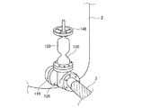
図5は、汚泥貯槽2に配設されたブロー配管100を示す斜視図である。このブロー配管100は、汚泥貯槽2から汚泥を排出するために設けられた排出口にバルブを設置したものであり、主として汚泥貯槽2との接続部110と、汚泥が流される本体部120と、バルブ装置130と、バルブ装置130の開/閉を制御するハンドル140とにより構成され、本体部120にはプロベスターのホース3が取り付けられている。
FIG. 5 is a perspective view showing the
このブロー配管100から汚泥貯槽2内の汚泥を排出する場合、ハンドル140を回転してバルブ装置130を開くと、汚泥貯槽2内に貯留されている汚泥及び水の自重によって、汚泥貯槽2内の汚泥が水とともに接続部110から本体部120を経由してホース3へ流される。しかし、汚泥は水に比べて比重が重いので、ホース3へ流されてもホース3の中に残留することが多かった。汚泥が残留した状態でホース3を外すと、残留した汚泥が周囲に飛び散ってしまい、環境汚染につながるため、このブロー配管100は実用的ではなく、実際にはあまり使用されていなかった。
When the sludge in the
図6は、汚泥貯槽2の上部開口からホース3を挿入した状態を示す断面図である。このように、汚泥貯槽2の上部開口にホース3を挿入し、ホース3から汚泥を吸引して排出する場合、汚泥貯槽2の中に作業員Mが入り、ブラシBのような道具を使用して汚泥をホース3の吸引口付近まで誘導する必要があった。そのため、作業員Mが転倒するおそれがあり、また、作業員Mが手作業で汚泥を誘導するため、作業に時間がかかっていた。
FIG. 6 is a cross-sectional view showing a state where the
このように、作業員Mが汚泥貯槽2の中に入って汚泥を排出する場合、作業員Mが作業しやすいように、移動可能な台車の前部に堆積物(例えば、砂、土、ごみ等)を切り崩すカッターを設け、台車の後部に切り崩した堆積物を吸引する吸引口を設けた堆積物の除去装置が知られている(例えば、特許文献1参照。)。この堆積物の除去装置は、作業員Mが台車を押しながら堆積物を切り崩し、吸引口から堆積物を吸引することにより、簡単に堆積物の除去作業を行えるようにした装置である。
Thus, when the worker M enters the
しかしながら、特許文献1に記載の堆積物の除去装置であっても、汚泥がホース3の中に残留することがあり、ホース3の中に残留する汚泥を確実に吸引させることは困難であった。
However, even with the deposit removal device described in Patent Document 1, sludge may remain in the
そこでこの発明は、プロベスターのホース内に残留する汚泥を確実に吸引して排出させることを可能にする汚泥排出配管装置を提供することを目的とする。 SUMMARY OF THE INVENTION Accordingly, an object of the present invention is to provide a sludge discharge piping device that makes it possible to reliably suck and discharge sludge remaining in a hose of a prober.
上記課題を解決するために、請求項1の発明は、汚泥を貯留する汚泥貯槽のブロー配管と、前記汚泥を吸引するプロベスターのホースの吸引口との間に取り付けられる汚泥排出配管装置であって、前記ブロー配管と前記吸引口とを連結する筒状部材と、前記筒状部材に水を供給するために前記筒状部材に設けられた給水配管と、を備え、前記汚泥を排出するとともに前記筒状部材に水が流されて前記ホースの中に残留する汚泥を流す、ことを特徴とする。 In order to solve the above-mentioned problems, the invention of claim 1 is a sludge discharge piping device attached between a blow pipe of a sludge storage tank for storing sludge and a suction port of a hose of a prober for sucking the sludge. A cylindrical member that connects the blow pipe and the suction port, and a water supply pipe provided in the cylindrical member for supplying water to the cylindrical member, and discharges the sludge. Water is caused to flow through the cylindrical member, and sludge remaining in the hose is caused to flow.
請求項2の発明は、請求項1に記載の汚泥排出配管装置において、前記筒状部材は、前記ブロー配管に取り付けられる筒状の配管接続部と、前記配管接続部に対して直列に連結され、前記吸引口に取り付けられる筒状の吸引口接続部と、を備え、前記配管接続部には、前記給水配管が設けられている、ことを特徴とする。 According to a second aspect of the present invention, in the sludge discharge piping apparatus according to the first aspect, the tubular member is connected in series to the tubular piping connection portion attached to the blow piping and the piping connection portion. And a cylindrical suction port connecting part attached to the suction port, wherein the water supply pipe is provided in the pipe connecting part.
請求項3の発明は、請求項1または2のいずれか1項に記載の汚泥排出配管装置において、前記給水配管は、前記筒状部材への給水を制御する給水バルブを備えた、ことを特徴とする。
Invention of
請求項1の発明によれば、ブロー配管と吸引口とを連結する筒状部材に、水を供給するための給水配管を設けたことにより、ホース内に汚泥が残留した状態であっても、給水配管から水を流すことにより、プロベスターによって流された水とともにホース内に残留している汚泥が吸引されるので、ホース内に残留する汚泥を確実にプロベスターに吸引させて排出させることが可能になる。 According to the invention of claim 1, even if the sludge remains in the hose by providing the water supply pipe for supplying water to the cylindrical member connecting the blow pipe and the suction port, By flowing water from the water supply pipe, the sludge remaining in the hose is sucked together with the water flowed by the probe, so the sludge remaining in the hose can be surely sucked and discharged by the probe. It becomes possible.
請求項2の発明によれば、筒状部材は、ブロー配管に取り付けられる筒状の配管接続部と、配管接続部に対して直列に連結されて吸引口に取り付けられる筒状の吸引口接続部と、を備えたことにより、筒状部材を2つの部材に分割可能にすることで加工しやすく、運搬しやすくするとともに、プロベスターのホースの大きさに合わせて吸引口接続部を交換することが可能になる。
According to invention of
請求項3の発明によれば、給水配管に筒状部材への給水を制御する給水バルブを設けたので、ホース内に残留する汚泥の量にあわせて適切な流量の水をホースに流すことを可能にする。
According to the invention of
以下、この発明を図示の実施の形態に基づいて説明する。 The present invention will be described below based on the illustrated embodiments.
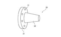
図1ないし図4は、この発明の実施の形態に係る汚泥排出配管装置1を示している。図1は、汚泥排出配管装置1が汚泥貯槽2に取り付けられた状態を示す斜視図であり、図2は、図1の汚泥排出配管装置1の外観を示す斜視図であり、図3は、図2の配管接続部10の外観を示す斜視図であり、図4は、図2の吸引口接続部20の外観を示す斜視図である。この汚泥排出配管装置1は、図1に示すように、汚泥貯槽2のブロー配管100とホース3との間に取り付けられ、汚泥貯槽2内の汚泥を排出するとともに、水が流されてホース3の中に残留する汚泥を流す装置であり、図2に示すように、主として配管接続部(筒状部材)10と、吸引口接続部(筒状部材)20と、給水配管30とを備えている。この汚泥排出配管装置1は、例えば、配管用炭素鋼により形成されている。なお、図1に示す汚泥貯槽2のブロー配管100は、図5に示すブロー配管100と同様に構成されている。
1 to 4 show a sludge discharge piping device 1 according to an embodiment of the present invention. 1 is a perspective view showing a state in which a sludge discharge piping device 1 is attached to a
配管接続部10は、ブロー配管100の本体部120に取り付けられて汚泥を流すための部材であり、筒状でブロー配管100に連結される開口部と、後述する吸引口接続部20に連結される開口部とが円板状に形成されている。この配管接続部10は、図3に示すように、主として配管連結部11と、本体部12と、下流連結部13とを備えている。
The
配管連結部11は、本体部120との連結箇所であり、円板状で中心に汚泥が流れる孔が形成され、本体部120に連結した際にボルトで固定できるようにネジ孔Hが円板上に数箇所(例えば、6箇所)形成されている。本体部12は、汚泥が流される箇所であり、配管連結部11の中心の孔から延設されて略円筒状に形成されている。下流連結部13は、吸引口接続部20との連結箇所であり、配管連結部11と略同様の形状に形成され、吸引口接続部20に連結した際にボルトで固定できるようにネジ孔Hが円板上に数箇所(例えば、6箇所)形成されている。
The
吸引口接続部20は、配管接続部10の下流連結部13に直列に連結され、ホース3の吸引口に取り付けられて汚泥を流すための部材であり、下流連結部13に連結される開口部が円板状に形成され、汚泥が流される箇所が略円錐形の筒状でホース3の吸引口側が細くなるように形成されている。この吸引口接続部20は、図4に示すように、主として上流連結部21と、本体部22とを備えている。
The suction
上流連結部21は、下流連結部13との連結箇所であり、下流連結部13と略同様の形状に形成され、下流連結部13に連結した際にボルトで固定できるようにネジ孔Hが円板上に数箇所(例えば、6箇所)形成されている。本体部22は、汚泥が流される箇所であり、上流連結部21の中心の孔から延設されて略円錐形の筒状でホース3の吸引口側が細くなるように形成されている。
The upstream connecting
給水配管30は、配管接続部10及び吸引口接続部20に水を供給するための配管であり、配管接続部10の本体部12から略垂直方向に設けられ、略円筒状で略L字型に屈折するように形成されている。この給水配管30は、図3に示すように、主として下流側配管部31と、給水バルブ32と、レバー33と、上流側配管部34とを備えている。
The
下流側配管部31は、配管接続部10へ水を流すための配管であり、本体部12から略垂直方向に設けられて略円筒状に形成されている。給水バルブ32は、上流側配管部34から流される水の流れを制御を行う装置である。レバー33は、給水バルブ32の開/閉を制御する装置である。上流側配管部34は、給水用の水道管に接続されて下流側配管部31へ水を流すための配管であり、下流側配管部31から略L字型に屈折して延設されて略円筒状に形成されている。
The downstream
次に、このような汚泥排出配管装置1の使用例等について、以下に説明する。 Next, the usage example etc. of such a sludge discharge piping apparatus 1 are demonstrated below.
汚泥貯槽2内に貯留されている汚泥を、ブロー配管100からプロベスターを使用して排出する場合の例を説明する。まず、汚泥貯槽2に配設されたブロー配管100の本体部120に、配管接続部10の配管連結部11を連結し、ネジ孔Hにボルトを挿入してナットにて固定する。配管接続部10の下流連結部13に、吸引口接続部20の上流連結部21を連結し、ネジ孔Hにボルトを挿入してナットにて固定する。さらに、吸引口接続部20の本体部22に、プロベスターのホース3の吸引口を取り付けると、図1のような状態になる。
An example in which the sludge stored in the
この状態で、プロベスターを稼働させ、ブロー配管100のハンドル140を回転させてバルブ装置130を開くと、汚泥貯槽2内に貯留されている汚泥及び水が、自重によりブロー配管100の接続部110から流れてくる。この汚泥及び水は、ブロー配管100の本体部120から配管接続部10の配管連結部11へ流れ、本体部12を経由して下流連結部13へ流れる。そして、吸引口接続部20の上流連結部21へ流れ、本体部22を経由してホース3へ流れる。その後、汚泥及び水は、プロベスターにより吸引される。
In this state, when the prober is operated and the
このとき、ホース3内に汚泥が残留することがある。そのため、この状態から、給水配管30の上流側配管部34に給水用の水道管を接続して、上流側配管部34に水を流し、レバー33を操作して給水バルブ32を開く。すると、この水は、給水配管30の下流側配管部31から配管接続部10の本体部12へ流れ、上述の汚泥と同様に下流連結部13、吸引口接続部20の上流連結部21、本体部22を経由してホース3へ流れ、プロベスターにより吸引される。この水の流れにより、ホース3内に残留していた汚泥も一緒にプロベスターへ流されて吸引される。
At this time, sludge may remain in the
このように、この汚泥排出配管装置1によれば、給水配管30を設け、上流側配管部34に給水用の水道管を接続し、配管接続部10の本体部12から下流連結部13、吸引口接続部20の上流連結部21、本体部22を経由してホース3へ水を流すことにより、ホース3内に残留していた汚泥も一緒にプロベスターへ流されて吸引されるので、ホース3内に残留する汚泥を確実にプリベスターに吸引させて排出させることが可能になる。
As described above, according to the sludge discharge piping device 1, the
また、配管接続部10と吸引口接続部20との2つの部材により筒状部材を構成したので、加工しやすく、運搬しやすくするとともに、プロベスターのホース3の大きさに合わせて吸引口接続部20を別の部材と交換することが可能になる。さらに、給水バルブ32とレバー33とを設けたことにより、ホース3内に残留していた汚泥の量に合わせて適切な流量の水をホース3内に流すことが可能になる。
In addition, since the tubular member is constituted by the two members of the
以上、この発明の実施の形態について説明したが、具体的な構成は、上記の実施の形態に限られるものではなく、この発明の要旨を逸脱しない範囲の設計の変更等があっても、この発明に含まれる。例えば、上述した実施の形態では、配管接続部10と吸引口接続部20との2つの部材により筒状部材を構成したが、1つの部材により構成しても良い。これにより、配管接続部10と吸引口接続部20との間からの水漏れを防止することができる。
Although the embodiment of the present invention has been described above, the specific configuration is not limited to the above embodiment, and even if there is a design change or the like without departing from the gist of the present invention, Included in the invention. For example, in the above-described embodiment, the tubular member is configured by the two members of the
また、上述した実施の形態では、給水配管30に給水バルブ32とレバー33とを設ける構成としたが、他の給水手段を用いても良く、例えば、汚泥貯槽2が設けられている施設内で発生する廃水を流すように構成しても良い。
In the above-described embodiment, the
1 汚泥排出配管装置
2 汚泥貯槽
3 ホース
10 配管接続部(筒状部材)
11 配管連結部
12 本体部
13 下流連結部
20 吸引口接続部(筒状部材)
21 上流連結部
22 本体部
30 給水配管
31 下流側配管部
32 給水バルブ
33 レバー
34 上流側配管部
100 ブロー配管
110 接続部
120 本体部
130 バルブ装置
140 ハンドル
B ブラシ
H ネジ孔
M 作業員
DESCRIPTION OF SYMBOLS 1 Sludge
DESCRIPTION OF
21
Claims (3)
前記ブロー配管と前記吸引口とを連結する筒状部材と、
前記筒状部材に水を供給するために前記筒状部材に設けられた給水配管と、を備え、
前記汚泥を排出するとともに前記筒状部材に水が流されて前記ホースの中に残留する汚泥を流す、
ことを特徴とする汚泥排出配管装置。 A sludge discharge piping device attached between a blow pipe of a sludge storage tank that stores sludge and a suction port of a hose of a prober that sucks the sludge,
A cylindrical member connecting the blow pipe and the suction port;
A water supply pipe provided in the tubular member for supplying water to the tubular member,
Draining the sludge and flowing the sludge remaining in the hose by flowing water into the tubular member;
A sludge discharge piping device characterized by that.
前記ブロー配管に取り付けられる筒状の配管接続部と、
前記配管接続部に対して直列に連結され、前記吸引口に取り付けられる筒状の吸引口接続部と、を備え、
前記配管接続部には、前記給水配管が設けられている、
ことを特徴とする請求項1に記載の汚泥排出配管装置。 The cylindrical member is
A tubular pipe connection portion attached to the blow pipe;
A cylindrical suction port connection portion connected in series to the pipe connection portion and attached to the suction port;
In the pipe connection part, the water supply pipe is provided.
The sludge discharge piping apparatus according to claim 1.
前記筒状部材への給水を制御する給水バルブを備えた、
ことを特徴とする請求項1または2のいずれか1項に記載の汚泥排出配管装置。
The water supply pipe is
A water supply valve for controlling water supply to the tubular member;
The sludge discharge piping apparatus according to any one of claims 1 and 2.
Priority Applications (1)
| Application Number | Priority Date | Filing Date | Title |
|---|---|---|---|
| JP2016083365A JP6662170B2 (en) | 2016-04-19 | 2016-04-19 | Sludge discharge piping device |
Applications Claiming Priority (1)
| Application Number | Priority Date | Filing Date | Title |
|---|---|---|---|
| JP2016083365A JP6662170B2 (en) | 2016-04-19 | 2016-04-19 | Sludge discharge piping device |
Publications (2)
| Publication Number | Publication Date |
|---|---|
| JP2017192879A true JP2017192879A (en) | 2017-10-26 |
| JP6662170B2 JP6662170B2 (en) | 2020-03-11 |
Family
ID=60154472
Family Applications (1)
| Application Number | Title | Priority Date | Filing Date |
|---|---|---|---|
| JP2016083365A Active JP6662170B2 (en) | 2016-04-19 | 2016-04-19 | Sludge discharge piping device |
Country Status (1)
| Country | Link |
|---|---|
| JP (1) | JP6662170B2 (en) |
Cited By (1)
| Publication number | Priority date | Publication date | Assignee | Title |
|---|---|---|---|---|
| CN119118353A (en) * | 2024-11-08 | 2024-12-13 | 湖南北控威保特环境科技股份有限公司 | High-efficiency deammoniation device and treatment method for kitchen waste biogas slurry |
Citations (9)
| Publication number | Priority date | Publication date | Assignee | Title |
|---|---|---|---|---|
| JPS5188070U (en) * | 1975-01-10 | 1976-07-14 | ||
| JPS54108415U (en) * | 1978-01-18 | 1979-07-31 | ||
| JPS5899591A (en) * | 1981-08-21 | 1983-06-13 | ドラガドス・イ・エクイポス・ソシエダド・アノニマ | Double wall joint |
| JPS61188673U (en) * | 1985-05-15 | 1986-11-25 | ||
| JPS6281699U (en) * | 1985-11-13 | 1987-05-25 | ||
| JPH02159500A (en) * | 1988-12-13 | 1990-06-19 | Pub Works Res Inst Ministry Of Constr | Forced feed facilitating pipe for pipe |
| JP3081832U (en) * | 2001-04-12 | 2001-11-22 | 日立機電工業株式会社 | Drain valve device |
| JP2010084627A (en) * | 2008-09-30 | 2010-04-15 | Shinmaywa Industries Ltd | Suction device and suction vehicle |
| JP2012217969A (en) * | 2011-04-13 | 2012-11-12 | Nekken Sangyo Kk | Cleaning device for surplus sludge transfer pipe |
-
2016
- 2016-04-19 JP JP2016083365A patent/JP6662170B2/en active Active
Patent Citations (9)
| Publication number | Priority date | Publication date | Assignee | Title |
|---|---|---|---|---|
| JPS5188070U (en) * | 1975-01-10 | 1976-07-14 | ||
| JPS54108415U (en) * | 1978-01-18 | 1979-07-31 | ||
| JPS5899591A (en) * | 1981-08-21 | 1983-06-13 | ドラガドス・イ・エクイポス・ソシエダド・アノニマ | Double wall joint |
| JPS61188673U (en) * | 1985-05-15 | 1986-11-25 | ||
| JPS6281699U (en) * | 1985-11-13 | 1987-05-25 | ||
| JPH02159500A (en) * | 1988-12-13 | 1990-06-19 | Pub Works Res Inst Ministry Of Constr | Forced feed facilitating pipe for pipe |
| JP3081832U (en) * | 2001-04-12 | 2001-11-22 | 日立機電工業株式会社 | Drain valve device |
| JP2010084627A (en) * | 2008-09-30 | 2010-04-15 | Shinmaywa Industries Ltd | Suction device and suction vehicle |
| JP2012217969A (en) * | 2011-04-13 | 2012-11-12 | Nekken Sangyo Kk | Cleaning device for surplus sludge transfer pipe |
Cited By (1)
| Publication number | Priority date | Publication date | Assignee | Title |
|---|---|---|---|---|
| CN119118353A (en) * | 2024-11-08 | 2024-12-13 | 湖南北控威保特环境科技股份有限公司 | High-efficiency deammoniation device and treatment method for kitchen waste biogas slurry |
Also Published As
| Publication number | Publication date |
|---|---|
| JP6662170B2 (en) | 2020-03-11 |
Similar Documents
| Publication | Publication Date | Title |
|---|---|---|
| ATE390538T1 (en) | PROPANT RECOVERY SYSTEM | |
| JP6662170B2 (en) | Sludge discharge piping device | |
| CN103505913A (en) | Grit removal device for grit chamber | |
| CN103011626B (en) | Vertical lime-dispersion machine with automatic slag-removing function | |
| KR100796948B1 (en) | Shot blasting device for processing large cylindrical steel pipes | |
| MY162543A (en) | Device and method for melting asphalt | |
| CN205352763U (en) | Product oil storage tank sampling device | |
| CN205216366U (en) | PCB brush mill copper powder recovery unit in production of high density laminated board | |
| CN202147220U (en) | Device for recycling and reusing grinding liquid | |
| CN201519686U (en) | Device for removing sediments in container | |
| CN206156885U (en) | Chemical wastewater discharges filter equipment | |
| CN205613224U (en) | A compressed air purification device | |
| CN204172207U (en) | A kind of multi-line cutting machine filtered for mortar | |
| CN105170578A (en) | Device automatically removing blockage of waste liquid discharge pipe | |
| CN202081112U (en) | Suction separation device for steel slag at bottom of deep water pool | |
| CN201309123Y (en) | Shot blasting machine | |
| CN203935657U (en) | A kind of air Continuous Flow sand filter is carried sand device | |
| CN202953337U (en) | Catalyst measuring tank | |
| CN205525956U (en) | Sump oil wastewater recovery device with automatic silt cleaning device | |
| CN204074647U (en) | Water supply line deslagging device | |
| CN205133991U (en) | A sewage cycle utilizes device for woollen blanket rinsing machine | |
| CN203203048U (en) | Boiler spiral dust removing device for absolute ethyl alcohol production line | |
| CN104028034A (en) | Slag discharge collector of filter | |
| CN205892153U (en) | Granule storage draw -out device | |
| CN203836977U (en) | Slag extractor with buffer water tank device |
Legal Events
| Date | Code | Title | Description |
|---|---|---|---|
| A621 | Written request for application examination |
Free format text: JAPANESE INTERMEDIATE CODE: A621 Effective date: 20190320 |
|
| A977 | Report on retrieval |
Free format text: JAPANESE INTERMEDIATE CODE: A971007 Effective date: 20191217 |
|
| TRDD | Decision of grant or rejection written | ||
| A01 | Written decision to grant a patent or to grant a registration (utility model) |
Free format text: JAPANESE INTERMEDIATE CODE: A01 Effective date: 20200114 |
|
| A61 | First payment of annual fees (during grant procedure) |
Free format text: JAPANESE INTERMEDIATE CODE: A61 Effective date: 20200127 |
|
| R150 | Certificate of patent or registration of utility model |
Ref document number: 6662170 Country of ref document: JP Free format text: JAPANESE INTERMEDIATE CODE: R150 |