JP2017192892A - Substrate support device - Google Patents
Substrate support device Download PDFInfo
- Publication number
- JP2017192892A JP2017192892A JP2016083729A JP2016083729A JP2017192892A JP 2017192892 A JP2017192892 A JP 2017192892A JP 2016083729 A JP2016083729 A JP 2016083729A JP 2016083729 A JP2016083729 A JP 2016083729A JP 2017192892 A JP2017192892 A JP 2017192892A
- Authority
- JP
- Japan
- Prior art keywords
- base material
- arm
- roller
- receiving
- support shaft
- Prior art date
- Legal status (The legal status is an assumption and is not a legal conclusion. Google has not performed a legal analysis and makes no representation as to the accuracy of the status listed.)
- Granted
Links
Images

Landscapes
- Coating Apparatus (AREA)
Abstract
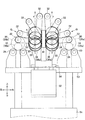
【課題】暴れや撓みを防ぎつつ長尺基材を回転可能に支持する基材支持装置の提供。【解決手段】基材10を回転可能に下方から支持する受けローラ部と、基材を上方から押える押えローラ部を備え、押えローラ部は、基材に当接する押えローラ32と、先端に押えローラを回転可能に支持すると共に、受けローラ部の側方に位置する基端に支軸35を有し、支軸を中心として倒れて押えローラを基材に当接させた押え位置と、起立して押えローラを基材の側方へ退避させた離脱位置との間で旋回するアーム34と、支軸を回転させると同時に上下方向に移動するアーム駆動部とを有する。押え位置から離脱位置へアームが旋回する時には、押えローラが基材から離れるようにアームを旋回させると同時に支軸を上方へ移動し、離脱位置から押え位置へアームを旋回させる時には、押えローラが基材に近づくようにアームを旋回させると同時に支軸を下方へ移動する基材支持装置。【選択図】図10PROBLEM TO BE SOLVED: To provide a base material support device for rotatably supporting a long base material while preventing rampage and bending. SOLUTION: A receiving roller portion that rotatably supports a base material 10 from below and a pressing roller portion that presses the base material from above are provided, and the pressing roller portion includes a pressing roller 32 that abuts on the base material and a pressing end. Along with rotatably supporting the roller, it has a support shaft 35 at the base end located on the side of the receiving roller portion, and the holding position where the holding roller is brought into contact with the base material by falling down around the supporting shaft and standing upright. It has an arm 34 that swivels with a detaching position in which the presser roller is retracted to the side of the base material, and an arm drive unit that rotates the support shaft and at the same time moves in the vertical direction. When the arm turns from the holding position to the release position, the holding roller turns the arm so as to separate from the base material, and at the same time, the support shaft moves upward, and when the arm is turned from the holding position to the holding position, the holding roller moves. A base material support device that rotates the arm so as to approach the base material and at the same time moves the support shaft downward. [Selection diagram] FIG. 10
Description
本発明は、基材支持装置に係り、特に、円形の断面形状を有する長尺の基材に対して溶射などの各種の加工を行うときに当該基材をローラによって回転可能に支持する装置に関する。 The present invention relates to a substrate support device, and more particularly to a device that rotatably supports a substrate by a roller when performing various processes such as thermal spraying on a long substrate having a circular cross-sectional shape. .
鋼管のような長尺の基材を加工するために当該基材を回転可能に支持する装置が必要となることがある。例えば、ボイラー配管に使用されるボイラーチューブの外表面に溶射加工を行うような場合である。 In order to process a long base material such as a steel pipe, an apparatus for supporting the base material rotatably may be required. For example, it is a case where thermal spraying is performed on the outer surface of a boiler tube used for boiler piping.
加工にあたっては、加熱により溶融または半溶融にした金属やセラミックス、サーメット等の粒子(溶射材)を溶射ガンから噴射させて基材の表面に吹き付けるが、このとき、基材の端部をチャックで把持してモータにより回転させる。これにより、基材の外周面に均一な溶射皮膜を形成することが出来る。 In processing, particles (spraying material) such as metal, ceramics, and cermet melted or semi-molten by heating are sprayed from the spray gun and sprayed onto the surface of the substrate. Hold and rotate by motor. Thereby, a uniform sprayed coating can be formed on the outer peripheral surface of the substrate.
また溶射のほかにも、ブラスト処理や研削加工、研磨加工など、様々な機械加工において基材を回転可能に支持する装置が必要とされることがある。 In addition to thermal spraying, an apparatus that rotatably supports a substrate may be required in various machining processes such as blasting, grinding, and polishing.
さらに下記特許文献1は、長尺の基材を回転させながら溶射する技術を開示するものである。
Furthermore, the following
ところで、ボイラーチューブのような金属管であっても長さが長くなったり径が細くなるとこれを真っ直ぐ水平に支持することは必ずしも容易ではなく、基材が自重で撓んで加工精度が低下する問題が生じ得る。 By the way, even if it is a metal tube such as a boiler tube, it is not always easy to support it straight and horizontally when the length is long or the diameter is thin, and the base material is bent by its own weight and the processing accuracy is lowered. Can occur.
このため、前記特許文献1に記載の発明では、基材の両端をチャックで把持し、基材に撓みがなくなるまで両端から張力を加えることで基材を水平に保持する。しかしながら、基材の長さが長くなったり、径が細い場合、あるいは基材の重量が大きくなるほど撓みが生じやすくなり、基材に加えられる張力にも限度がある。
For this reason, in the invention described in
また当該張力は、撓みを小さくするには大きいほうが望ましい一方で、塑性変形が生じる大きさ未満に抑える必要があり、基材の種類(材料や径、肉厚等)によって撓みやすさも塑性変形を生じさせない限界値も変わるから、様々な基材を次々と加工するような場合には、張力の調整が煩雑で加工効率が必ずしも良好とは言えない面がある。 In addition, while it is desirable that the tension is large in order to reduce the deflection, it is necessary to suppress the tension to less than the size at which plastic deformation occurs, and the ease of bending depends on the type of substrate (material, diameter, wall thickness, etc.). Since the limit value that does not occur also changes, when various substrates are processed one after another, there are aspects in which the adjustment of the tension is complicated and the processing efficiency is not necessarily good.
なお、基材を垂直に支持すれば上記のような撓みの問題を回避できるが、長さが例えば十メートル近く、或いは、十数メートル以上にもなる長尺の基材を工場内で垂直に支持して加工することは現実的ではない。 In addition, if the base material is supported vertically, the above-mentioned problem of bending can be avoided, but a long base material having a length of, for example, nearly 10 meters or more than a dozen meters or more can be vertically installed in the factory. Supporting and processing is not realistic.
一方、上記のような張力によらず、ローラによって基材を支持することも考えられる。基材を載せられるように一定の間隔を隔てて配置した一対のローラを備えたローラ装置を直線状に(基材の長さ方向に)複数配列し、これらのローラ装置によって基材の両端部のみならず中間部についても支持するのである。基材の長さが長くなっても、ローラ装置の数を増やせば対応することが出来る。またローラ装置同士の間隔を小さくすれば、撓みを生じ難くすることが出来る。 On the other hand, it is also conceivable that the substrate is supported by a roller regardless of the tension as described above. A plurality of roller devices each having a pair of rollers arranged at regular intervals so that the base material can be placed are arranged linearly (in the length direction of the base material), and both end portions of the base material are formed by these roller devices. It supports not only the middle part. Even if the length of the substrate becomes long, it can be coped with by increasing the number of roller devices. Further, if the distance between the roller devices is reduced, it is possible to make it difficult for the bending to occur.
ところが、このように単純にローラに載せただけでは、加工中に基材が暴れる(ローラから浮き上がったり波打ったりする)おそれがある。特に、基材が比較的軽量で長い場合や、径が細い場合、基材を回転させる速度が速い場合などには基材が暴れやすく、このような暴れが生じれば加工精度が低下し、製品品質の劣化に繋がる。 However, if the substrate is simply placed on the roller in this way, the substrate may be violated during processing (floating or wavy from the roller). In particular, when the base material is relatively light and long, when the diameter is thin, when the speed of rotating the base material is high, the base material is prone to rampage, and if such rampage occurs, the processing accuracy decreases, It leads to product quality degradation.
したがって、本発明の目的は、長尺の基材を暴れや撓みを防ぎつつ水平に回転可能に支持することにある。 Accordingly, an object of the present invention is to support a long base material so as to be horizontally rotatable while preventing violence and bending.
前記課題を解決し目的を達成するため、本発明に係る基材支持装置は、円形の横断面を有する長尺の基材を軸周りに回転可能に支持できるように間隔を隔てて配列させた2以上のローラ装置を備えた基材支持装置であって、前記ローラ装置は、基材を軸周りに回転できるように下方から支持する受けローラ部と、当該受けローラ部に支持された基材の外周面に上方から当接して基材の軸周りの回転を許容しつつ基材を上方から押える押えローラ部とを備える。 In order to solve the above-described problems and achieve the object, the base material support device according to the present invention is arranged with an interval so that a long base material having a circular cross section can be rotatably supported around an axis. A base material support device including two or more roller devices, wherein the roller device supports a base material from below so that the base material can be rotated around an axis, and a base material supported by the support roller portion. And a pressing roller portion that presses the base material from above while allowing contact with the outer peripheral surface of the base material from above and allowing rotation about the axis of the base material.
上記押えローラ部は、上記受けローラ部に支持された基材の外周面に上方から当接して基材の回転を受けて回転し、基材の軸周りの回転を許容しつつ基材を上方から押える押えローラと、先端部に押えローラを回転可能に支持するとともに、受けローラ部の側方に位置する基端部に支軸を有し、この支軸を中心として、倒れて押えローラを基材に当接させた押え位置と、起立して押えローラを基材の側方へ退避させた離脱位置との間で旋回することが可能なアームと、前記支軸を回転させると同時に上下方向に移動するアーム駆動部とを有する。 The presser roller part contacts the outer peripheral surface of the base material supported by the receiving roller part from above and rotates by receiving the rotation of the base material. The presser roller that is pressed from the top, and the presser roller is rotatably supported at the tip, and has a support shaft at the base end located on the side of the receiving roller, and the presser roller is tilted around this support shaft. An arm that can be swung between a press position that is in contact with the base material and a release position that is erected and retracts the press roller to the side of the base material; And an arm driving unit that moves in the direction.
そして、上記アーム駆動部は、押え位置から離脱位置へアームを旋回させるときには、押えローラが基材から離れるようにアームを旋回させると同時に上記支軸を上方へ移動する一方、離脱位置から押え位置へアームを旋回させるときには、押えローラが基材に近づくようにアームを旋回させると同時に上記支軸を下方へ移動する。 When the arm drive unit pivots the arm from the presser position to the release position, the arm drive unit rotates the arm so that the presser roller moves away from the base material and simultaneously moves the support shaft upward, while the presser position from the release position to the presser position. When the arm is turned, the arm is turned so that the presser roller approaches the substrate, and at the same time, the support shaft is moved downward.
本発明に係る基材支持装置では、基材をその長さ方向に配列した複数の受けローラ(ローラ装置)によって下方から支持するから、基材を水平に真っ直ぐに保持することが出来る。一方、この支持状態で上方から押えローラによって基材を押え付けることにより、受けローラに載せた基材が浮き上がることを防ぐことが出来る。言い換えれば、基材は、受けローラと押えローラとによって挟まれる(囲まれる)ように支持される。なお、このように基材を支持しても、受けローラと押えローラはともに回転可能に設置してあり、基材の回転力を受けて回転するから基材の回転が妨げられることはない。また、押えローラは基材から離脱させることが出来るから、支持装置への基材の搬入や搬出の邪魔になることもない。 In the base material support device according to the present invention, since the base material is supported from below by a plurality of receiving rollers (roller devices) arranged in the length direction, the base material can be held horizontally and straight. On the other hand, by pressing the substrate with the pressing roller from above in this supported state, the substrate placed on the receiving roller can be prevented from floating. In other words, the base material is supported so as to be sandwiched (enclosed) by the receiving roller and the pressing roller. Even if the base material is supported in this manner, both the receiving roller and the presser roller are rotatably installed and rotate by receiving the rotational force of the base material, so that the rotation of the base material is not hindered. Further, since the press roller can be detached from the base material, it does not obstruct the carrying or unloading of the base material to / from the support device.
受けローラ部は、典型的には、回転軸が互いに平行になるように一定の間隔を隔てて配列させた一対の受けローラを備え、これら一対の受けローラの間に基材を載せることにより当該基材を回転可能に支持する。 The receiving roller section typically includes a pair of receiving rollers arranged at a predetermined interval so that the rotation axes thereof are parallel to each other, and a base material is placed between the pair of receiving rollers. A substrate is rotatably supported.
またアーム駆動部は、典型的には、アームの基端部に備えた歯車(ピニオン)と、上下方向に延在し前記歯車と噛み合うラックと、アームの基端部を上下方向に移動させる駆動装置とを備え、当該駆動装置によって前記歯車を上下動させることにより、前記支軸を上下動させると同時に回転させアームを旋回させる。 The arm drive section typically has a gear (pinion) provided at the base end of the arm, a rack extending in the vertical direction and meshing with the gear, and a drive for moving the base end of the arm in the vertical direction. And moving the gear up and down by the drive device, the support shaft is moved up and down and simultaneously rotated to turn the arm.
さらに、受けローラ部は、受けローラが基材に当接する支持位置と、当該支持位置より下方へ移動した退避位置との間で上下動が可能であり、押えローラ部は、受けローラ部が支持位置と退避位置との間で上下動するときに、当該受けローラ部と一緒に上下動し、受けローラ部が退避位置へ向け下降するときには、アーム駆動部がアームを離脱位置に配置するようにしても良い。 Further, the receiving roller portion can move up and down between a support position where the receiving roller contacts the base material and a retracted position moved downward from the support position. The holding roller portion is supported by the receiving roller portion. When moving up and down between the position and the retracted position, it moves up and down together with the receiving roller section, and when the receiving roller section descends to the retracted position, the arm drive section places the arm in the disengaged position. May be.
このような態様によれば、基材に対して加工を施す装置部分(例えば後に述べる実施形態の溶射部)を通過するときに基材に当接しているローラ(受けローラおよび押えローラ)を基材から離脱退避させ、ローラが加工の邪魔になることを防ぐことが出来る。 According to such an aspect, the rollers (the receiving roller and the presser roller) that are in contact with the base material when passing through an apparatus portion that performs processing on the base material (for example, a sprayed portion in an embodiment described later) are used as the base. It is possible to prevent the rollers from getting in the way of processing by separating and retreating from the material.
また、上記本発明に係る基材支持装置は、基材を回転させる回転駆動手段(例えばモータ)と、基材を把持して当該回転駆動手段で発生される回転力を基材に伝達する基材把持部(例えばチャック)とを備えることがある。 Further, the base material support device according to the present invention includes a rotation driving means (for example, a motor) that rotates the base material, and a base that grips the base material and transmits the rotational force generated by the rotation driving means to the base material. A material grip part (for example, chuck) may be provided.
さらに、基材に対して軸方向の押圧力を加える押圧部を備えても良く、加工中このような押圧力を加えれば、基材の暴れをより一層確実に防ぐことが出来る。 Furthermore, you may provide the press part which applies the axial direction pressing force with respect to a base material, and if such a pressing force is applied during a process, the base material can be prevented more reliably.
本発明では、同時に複数本の基材を支持できる装置を構成することも可能である。 In the present invention, it is also possible to constitute an apparatus capable of supporting a plurality of substrates at the same time.
具体的には、当該装置は、円形の横断面を有する長尺の基材を軸周りに回転可能に支持できるように間隔を隔てて配列させた2以上のローラ装置を備えた基材支持装置であるが、前記基材として第一基材と第二基材とを平行に支持できるように前記ローラ装置は、第一基材を軸周りに回転できるように下方から支持する第一受けローラ部と、第二基材を軸周りに回転できるように下方から支持する第二受けローラ部と、第一受けローラ部および第二受けローラ部にそれぞれ支持された第一基材および第二基材を、軸周りの回転を許容しつつ上方から押える押えローラ部とを備える。 Specifically, the apparatus includes a base material support device including two or more roller devices arranged so as to be capable of rotatably supporting a long base material having a circular cross section around an axis. However, the roller device supports the first base material from below so that the first base material and the second base material can be supported in parallel as the base material so that the first base material can be rotated around the axis. A second receiving roller part that supports the second base material from below so that the second base material can be rotated about the axis, and a first base material and a second base material supported by the first receiving roller part and the second receiving roller part, respectively. A pressing roller portion that presses the material from above while allowing rotation around the axis.
また上記押えローラ部は、第一基材の外周面に上方から当接して当該基材の回転を受けて回転し、当該第一基材の軸周りの回転を許容しつつ当該基材を上方から押える第一押えローラと、先端部に第一押えローラを回転可能に支持するとともに、第一受けローラ部と第二受けローラ部との間に位置する基端部に支軸を有し、この支軸を中心として、倒れて第一押えローラを第一基材に当接させた押え位置と、起立して第一押えローラを第一受けローラ部と第二受けローラ部との間に退避させた離脱位置との間で旋回することが可能な第一アームと、第二基材の外周面に上方から当接して当該基材の回転を受けて回転し、当該第二基材の軸周りの回転を許容しつつ当該基材を上方から押える第二押えローラと、先端部に第二押えローラを回転可能に支持するとともに、第一受けローラ部と第二受けローラ部との間に位置する基端部に支軸を有し、この支軸を中心として、倒れて第二押えローラを第二基材に当接させた押え位置と、起立して第二押えローラを第一受けローラ部と第二受けローラ部との間に退避させた離脱位置との間で旋回することが可能な第二アームと、第一アームの支軸および第二アームの支軸を回転させると同時に上下方向に移動するアーム駆動部とを有する。 Further, the presser roller portion contacts the outer peripheral surface of the first base material from above and receives the rotation of the base material to rotate, and allows the base material to rotate upward while allowing rotation around the axis of the first base material. A first presser roller that presses from the first end, and a first presser roller rotatably supported at the tip, and a support shaft at a base end located between the first receiving roller part and the second receiving roller part, Centering on this support shaft, the presser position where the first presser roller is brought into contact with the first base material and the first presser roller standing up between the first receiving roller part and the second receiving roller part. The first arm capable of turning between the retracted and retracted position, and the outer surface of the second base material is contacted from above and rotated by the rotation of the base material. A second presser roller that presses the substrate from above while allowing rotation around the shaft, and a second presser roller that rotates at the tip And has a support shaft at a base end portion located between the first receiving roller portion and the second receiving roller portion, and the second presser roller is tilted around the support shaft and the second presser roller is moved to the second base material. A second arm capable of rotating between a press position brought into contact with the head and a disengagement position in which the second press roller is raised and retracted between the first receiving roller portion and the second receiving roller portion And an arm driving unit that rotates the support shaft of the first arm and the support shaft of the second arm and simultaneously moves in the vertical direction.
さらに上記アーム駆動部は、押え位置から離脱位置へ第一アームと第二アームを旋回させるときには、第一押えローラが第一基材から離れ且つ第二押えローラが第二基材から離れるように第一アームと第二アームを旋回させると同時に第一アームの支軸と第二アームの支軸を上方へ移動する。一方、離脱位置から押え位置へ第一アームと第二アームを旋回させるときには、当該アーム駆動部は、第一押えローラが第一基材へ近づき且つ第二押えローラが第二基材へ近づくように第一アームと第二アームを旋回させると同時に第一アームの支軸と第二アームの支軸を下方へ移動する。 Further, when the arm drive unit turns the first arm and the second arm from the press position to the release position, the first press roller is separated from the first base material and the second press roller is separated from the second base material. At the same time as turning the first arm and the second arm, the support shaft of the first arm and the support shaft of the second arm are moved upward. On the other hand, when the first arm and the second arm are turned from the disengagement position to the presser position, the arm drive unit causes the first presser roller to approach the first base material and the second presser roller to approach the second base material. The first arm and the second arm are pivoted simultaneously, and at the same time, the support shaft of the first arm and the support shaft of the second arm are moved downward.
また上記アーム駆動部は、第一アームの基端部に備えた第一歯車と、第二アームの基端部に備えた第二歯車と、上下方向に延在し且つ第一歯車と第二歯車との間に配置されて第一歯車と第二歯車とに噛み合うラックと、第一アームの基端部と第二アームの基端部を同時に上下方向に移動させる駆動装置とを備え、前記駆動装置によって第一歯車および第二歯車を上下動させることにより、第一アームの支軸と第二アームの支軸を上下動させると同時に回転させ、第一アームと第二アームを旋回させることを可能としても良い。 The arm drive unit includes a first gear provided at the base end portion of the first arm, a second gear provided at the base end portion of the second arm, the first gear and the second gear extending in the vertical direction. A rack that is arranged between the gear and meshes with the first gear and the second gear, and a driving device that simultaneously moves the base end of the first arm and the base end of the second arm in the vertical direction, The first gear and the second gear are moved up and down by the driving device, so that the support shaft of the first arm and the support shaft of the second arm are moved up and down at the same time, and the first arm and the second arm are turned. It is possible to make it possible.
本発明は直径に比べて長さ寸法が大きい長尺の部材を好ましく支持することが出来るが、支持対象である基材の種類(用途や構成材料等)は特に限定されない。例えばボイラー配管に使用されるボイラーチューブなどの金属管を支持するのに好適であるが、他の様々な材料(金属のほか、例えば樹脂や木材など)および用途の基材を支持することが可能である。また当該基材は、中空部材でも中実部材でも良い。 The present invention can preferably support a long member having a length that is larger than its diameter, but the type of substrate (use, constituent material, etc.) to be supported is not particularly limited. Suitable for supporting metal pipes such as boiler tubes used for boiler piping, for example, but can support various other materials (in addition to metals, such as resin and wood) and substrates for applications It is. The substrate may be a hollow member or a solid member.
さらに加工についても特定のものに限定されず、本発明に言う「加工」には、溶射、ブラスト、研削加工(旋盤等)、研磨加工など、各種の加工が含まれる。 Further, the processing is not limited to a specific one, and the “processing” referred to in the present invention includes various types of processing such as thermal spraying, blasting, grinding (such as a lathe), and polishing.
本発明に係る基材支持装置によれば、長尺の基材を暴れや撓みを防ぎつつ水平に回転可能に支持することが出来る。 According to the base material support device of the present invention, it is possible to support a long base material so as to be able to rotate horizontally while preventing rampage and bending.
本発明の他の目的、特徴および利点は、図面に基づいて述べる以下の本発明の実施の形態の説明により明らかにする。なお、各図中、同一の符号は、同一又は相当部分を示す。 Other objects, features, and advantages of the present invention will become apparent from the following description of embodiments of the present invention described with reference to the drawings. In addition, in each figure, the same code | symbol shows the same or an equivalent part.
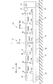
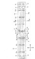
図1〜図2に示すように本発明の一実施形態に係る基材支持装置は、溶射加工を行うために加工対象である基材10(10a,10b)をローラ23,24,32によって回転可能に支持する装置である。基材10としては例えばボイラーチューブのような鋼管を対象とし、一定の間隔を隔てて基材10の長さ方向(前後方向)に配列させた複数のローラ装置21a,21b,21c,21d,21e,21f,21gによって当該基材10を水平に支持する。また、本実施形態では2本の基材10a,10bを同時に加工できるように2つの支持部(第一支持部11aおよび第二支持部11b/図2参照)を形成してあり、これらの支持部11a,11bを使用して2本の基材10a,10bを平行にそれぞれ支持する。
As shown in FIGS. 1-2, the base material support apparatus which concerns on one Embodiment of this invention rotates the base material 10 (10a, 10b) which is a process target by
各支持部11a,11bには、図3〜図10を参照して後に詳しく説明するローラ装置21a〜21gの受けローラ23,24と、押えローラ32がそれぞれ配置されるようにするとともに、基材10を軸周りに回転させるモータ14と、基材10の一端部(後端)を把持してモータ14の回転を基材10に伝達するチャック15と、基材10の他端部(前端)から基材10に軸方向圧縮力を加える押圧部16とを備える。
In each of the
また各支持部11a,11bには、溶射加工を行う溶射部17を備える。各溶射部17は、基材10に向け鉛直下方に溶射材を噴射する溶射ガン18と、溶射材を回収する溶射トレー19を有する。溶射トレー19は、溶射ガン18から噴射された溶射材を受け止めるため基材10の下側で且つ溶射ガン18の垂直下方位置に設置してある。溶射部17は固定してあり、基材10を移動させて加工を行う。
Moreover, each
このため本実施形態では、上記ローラ装置21a〜21g、モータ14、チャック15および押圧部16を台車12の上に搭載してある。台車12は、車輪13とモータ等の駆動装置(図示せず)を備えて前後方向に(前方および後方に)走行することが出来る。なお、各図には前後左右上下の方向を示す座標を表示しており、これらの方向に基づいて本実施形態の説明を行う。
Therefore, in the present embodiment, the
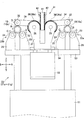
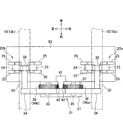
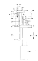
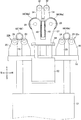
基材10を支持する各ローラ装置21a〜21gは、図3〜図5に示すように前記第一支持部11aにおいて第一基材10aを下方から支持する受けローラ部(第一受けローラ部)22aと、前記第二支持部11bにおいて第二基材10bを下方から支持する受けローラ部(第二受けローラ部)22bと、これら第一基材10aおよび第二基材10bを上方から押える押えローラ部31と、主エアシリンダ51とを備えている。受けローラ部22a,22bおよび押えローラ部31は主フレーム53に設置してあり、当該主フレーム53を介して主エアシリンダ51により、受けローラ部22a,22bおよび押えローラ部31全体を上下動させることが出来る。
As shown in FIGS. 3 to 5, each of the
主フレーム53の右端部および左端部にそれぞれ配置した各受けローラ部22a,22bは、基材10を載せることが出来るように基材10の外径より小さな間隔を隔てて左右に並べた一対の受けローラ23,24を有する。これらの受けローラ23,24は、前後に配置した支持板25の間に回転可能に軸支してあり、基材10の回転(矢印B参照)を受けて自由に回転(矢印C参照)することが出来る。
A pair of receiving
一方、押えローラ部31は、受けローラ23,24に載せた基材10に上方から当接する押えローラ32と、連結ロッド33を介して押えローラ32を回転可能に支持するアーム34と、アーム34を旋回させるためアーム34の基端部に固定した歯車36と、歯車36と噛み合うラック41と、アーム34を回転可能に支持するアーム支持板37と、アーム支持板37を介してアーム34を上下動させる副エアシリンダ52とを有する。アーム34と歯車36は、アーム34の基端部に備えた支軸35によって、アーム支持板37に対して回転可能に支持してある。また押えローラ32は、前記受けローラ23,24と同様に基材10の回転を受けて自由に回転(矢印D参照)することが出来る。
On the other hand, the
上記押えローラ32、アーム34および歯車36は、第一受けローラ部22a(第一基材10a)および第二受けローラ部22b(第二基材10b)に対応して2つずつ備える。また、ラック41は左右両側に歯42を有し、右側の歯42は右側のアーム34の基端部に固定した歯車(第一歯車)36aと、左側の歯42は左側のアーム34の基端部に固定した歯車(第二歯車)36bとそれぞれ噛み合っている。
The
上記ラック41および副エアシリンダ52は主フレーム53に固定する一方、押えローラ32、アーム34、歯車36およびアーム支持板37は副フレーム54に固定する。したがってこの副フレーム54を、主フレーム53に固定した副エアシリンダ52によって上下動させると、押えローラ32、アーム34、歯車36およびアーム支持板37を主フレーム53に対して上下動させることが出来る。
The
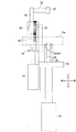
図6〜図7に示すように副エアシリンダ52によって副フレーム54を上方へ移動させると、左右の各アーム34も上方へ移動することとなるが、主フレーム53に固定されたラック41は移動しない。このため、ラック41と噛み合い各アーム36の基端部に固定されている歯車36は回転し(右側の第一歯車36aは反時計回りに、左側の第二歯車36bは時計回りにそれぞれ回転する/図10も参照)、各アーム34は、前記図3〜図5に示した略水平に倒れた状態から、図6〜図7に示す略垂直に起立した状態となり、アーム先端の押えローラ32は、前記図3〜図5に示した押え位置から図6〜図7に示す離脱位置に移動する。
As shown in FIGS. 6 to 7, when the
押えローラ32をこのように離脱位置に移動させれば、基材10を上方から例えばクレーンですくい上げて(持ち上げて)取り出すことが出来る。また、新たな基材を受けローラ23,24の上に搬入することが出来る。
If the
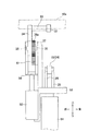
さらに、基材10を支持するローラ装置21a〜21gのうちの一部を基材10から退避させることも可能である。例えば、前記図1〜図2に示したように多数配列させたローラ装置21a〜21gのうちの一部のローラ装置21dについて、図8〜図9に示すように主エアシリンダ51によって主フレーム53を下方へ移動させる。すると、押えローラ部31とともに受けローラ部22a,22bも下方へ移動し、他のローラ装置21a〜21c,21e〜21gによって支持されている基材10から、ローラ装置21dの受けローラ23,24が離れる。
Furthermore, a part of the
押えローラ32を離脱させるとともに、上記のような退避位置に受けローラ23,24を退避させれば、溶射部17(図1〜図2参照)を通過するときにこれらのローラ23,24,32が加工の邪魔になることなく(押えローラ32が溶射材の吹き付けを妨げたり、受けローラ23,24が溶射トレー19に衝突することがない)、他のローラ装置21a〜21c,21e〜21gによって基材10の支持を維持しつつ基材10を移動させて加工を進めることが可能となる。
When the
主エアシリンダ51や副エアシリンダ52(各ローラ装置21a〜21g)の動作制御は、基材10(台車12)の移動に連動させてコンピュータによって制御することができ、溶射部17を通過するローラ装置21a〜21gの両エアシリンダ51,52を動作させて押えローラ32を離脱位置に、受けローラ23,24を退避位置にそれぞれ移動させ、通過後には、受けローラ23,24を支持位置に、押えローラ32を押え位置にそれぞれ復帰させるようにすれば良い。
The operation control of the
また、図10に示すように本実施形態の支持装置によれば、外径の異なる様々な基材10,20を安定して支持することが出来る。特に、押えローラ32は、基材10,20の頂上(最上端位置)又は当該位置に出来るだけ近い位置に当接させて基材10,20を押えることが一対の受けローラ23,24と押えローラ32の3点で安定的に基材10,20を保持する点で好ましいが、本実施形態によれば、アーム34を単純に旋回させるだけなく、アーム34(歯車36)の回転(矢印E参照)に伴ってアーム34の支軸35が上下方向に移動されるから(矢印F参照)、例えば外径が大きな基材20を支持する場合にはアーム34の支軸35が上方へ移動することとなり、単純にアーム34が旋回する構造と比べてより頂上に近い位置に押えローラ32を当接させることができ(符号G参照)、基材20を安定して保持することが可能となる。
As shown in FIG. 10, according to the support device of the present embodiment,
さらに本実施形態によれば、1つのシリンダ(副エアシリンダ52)でアーム34の旋回と支軸35の垂直移動の両方の操作を同時に行うことが出来るから、装置の小型化(基材の周囲に狭い空間しか取れない加工装置へも適用できる)および製造コストの点でも有利である。
Furthermore, according to the present embodiment, both the turning of the
以上、本発明の実施の形態について説明したが、本発明はこれらに限定されるものではなく、特許請求の範囲に記載の範囲内で種々の変更を行うことができることは当業者に明らかである。 As mentioned above, although embodiment of this invention was described, this invention is not limited to these, It is clear to those skilled in the art that a various change can be made within the range as described in a claim. .
例えば、前記実施形態ではアームの操作にラックと歯車を用いたが、ピンやワイヤ、ベルト、摩擦板などを使用して同様にアームを動作させるように変更することも出来る。また、前記実施形態では2本の基材を支持する装置としたが、1本の基材を支持する装置としても良いし、3つ以上の支持部を備えることにより3本以上の基材を支持可能な装置を同様に構成することも可能である。さらに、前記実施形態では支持装置を走行(移動)可能としたが、本発明の支持装置は床などに固定された走行できない構造であっても構わない。また本発明に言う「加工」は溶射に限られず、様々な加工が含まれることは既に述べたとおりである。 For example, in the above-described embodiment, a rack and a gear are used for the operation of the arm. However, the arm can be similarly changed to operate using a pin, a wire, a belt, a friction plate, or the like. Moreover, although it was set as the apparatus which supports two base materials in the said embodiment, it is good also as an apparatus which supports one base material, and three or more base materials are provided by providing three or more support parts. A supportable device can be similarly constructed. Furthermore, although the support device can travel (move) in the embodiment, the support device of the present invention may have a structure that is fixed to a floor or the like and cannot travel. The “processing” referred to in the present invention is not limited to thermal spraying, but includes various processing as described above.
10(10a,10b),20(20a,20b) 基材
11 基材支持装置
11a 支持部(第一支持部)
11b 支持部(第二支持部)
12 台車
13 車輪
14 モータ
15 チャック
16 押圧部
17 溶射部
18 溶射ガン
19 溶射トレー
21a,21b,21c,21d,21e,21f,21g ローラ装置
22a 受けローラ部(第一受けローラ部)
22b 受けローラ部(第二受けローラ部)
23,24 受けローラ
31 押えローラ部
32 押えローラ
33 連結ロッド
34 アーム
35 支軸
36a 歯車(第一歯車)
36b 歯車(第二歯車)
37 アーム支持板
41 ラック
42 ラックの歯
51 主エアシリンダ
52 副エアシリンダ
53 主フレーム
54 副フレーム
10 (10a, 10b), 20 (20a, 20b)
11b Support part (second support part)
12
22b Receiving roller part (second receiving roller part)
23, 24 Receiving
36b Gear (second gear)
37
Claims (9)
前記ローラ装置は、
前記基材を軸周りに回転できるように下方から支持する受けローラ部と、
当該受けローラ部に支持された前記基材の外周面に上方から当接して当該基材の軸周りの回転を許容しつつ当該基材を上方から押える押えローラ部と
を備え、
前記押えローラ部は、
前記受けローラ部に支持された前記基材の外周面に上方から当接して前記基材の回転を受けて回転し、当該基材の軸周りの回転を許容しつつ当該基材を上方から押える押えローラと、
先端部に前記押えローラを回転可能に支持するとともに、前記受けローラ部の側方に位置する基端部に支軸を有し、この支軸を中心として、倒れて前記押えローラを前記基材に当接させた押え位置と、起立して前記押えローラを前記基材の側方へ退避させた離脱位置との間で旋回することが可能なアームと、
前記支軸を回転させると同時に上下方向に移動するアーム駆動部と
を有し、
前記アーム駆動部は、
前記押え位置から前記離脱位置へ前記アームを旋回させるときには、前記押えローラが前記基材から離れるように前記アームを旋回させると同時に前記支軸を上方へ移動する一方、
前記離脱位置から前記押え位置へ前記アームを旋回させるときには、前記押えローラが前記基材に近づくように前記アームを旋回させると同時に前記支軸を下方へ移動する
ことを特徴とする基材支持装置。 A substrate support device comprising two or more roller devices arranged so as to be capable of rotatably supporting a long substrate having a circular cross section around an axis,
The roller device is
A receiving roller part that supports the base material from below so that the base material can be rotated around an axis;
A pressing roller portion that comes into contact with the outer peripheral surface of the base material supported by the receiving roller portion from above and presses the base material from above while allowing rotation around the axis of the base material.
The presser roller portion is
Abutting from above on the outer peripheral surface of the base material supported by the receiving roller portion, the base material is rotated by receiving the rotation of the base material, and the base material is pressed from above while allowing rotation around the axis of the base material. A presser roller,
The presser roller is rotatably supported at the distal end portion, and has a support shaft at a base end portion located on the side of the receiving roller portion, and the presser roller is tilted around the support shaft and is placed on the base material. An arm capable of turning between a press position abutted on and a disengagement position where the press roller is raised and retracted to the side of the base material;
An arm drive unit that moves up and down at the same time as rotating the support shaft,
The arm drive unit is
When turning the arm from the presser position to the disengagement position, the arm is turned so that the presser roller is separated from the base material, and at the same time the support shaft is moved upward,
When rotating the arm from the disengagement position to the presser position, the support shaft is moved downward simultaneously with turning the arm so that the presser roller approaches the base material. .
これら一対の受けローラの間に前記基材を載せることにより前記基材を回転可能に支持できるようにした
請求項1に記載の基材支持装置。 The receiving roller portion includes a pair of receiving rollers arranged at a predetermined interval so that the rotation shafts are parallel to each other.
The base material support apparatus according to claim 1, wherein the base material can be rotatably supported by placing the base material between the pair of receiving rollers.
前記アームの基端部に備えた歯車と、
上下方向に延在し前記歯車と噛み合うラックと、
前記アームの基端部を上下方向に移動させる駆動装置と
を備え、
前記駆動装置によって前記歯車を上下動させることにより、前記支軸を上下動させると同時に回転させ、前記アームを旋回させることを可能とした
請求項1または2に記載の基材支持装置。 The arm drive unit is
A gear provided at the proximal end of the arm;
A rack extending in the vertical direction and meshing with the gear;
A drive device for moving the base end of the arm in the vertical direction,
The base material support device according to claim 1, wherein the gear is moved up and down by the driving device, whereby the support shaft is moved up and down and simultaneously rotated to turn the arm.
前記押えローラ部は、
前記受けローラ部が前記支持位置と前記退避位置との間で上下動するときに、当該受けローラ部と一緒に上下動し、
前記受けローラ部が前記退避位置へ向け下降するときには、前記アーム駆動部は、前記アームを前記離脱位置に配置する
請求項1から3のいずれか一項に記載の基材支持装置。 The receiving roller portion can move up and down between a supporting position where the receiving roller contacts the base material and a retracted position moved downward from the supporting position,
The presser roller portion is
When the receiving roller part moves up and down between the support position and the retracted position, it moves up and down together with the receiving roller part,
The base material support device according to any one of claims 1 to 3, wherein when the receiving roller unit is lowered toward the retracted position, the arm driving unit arranges the arm at the disengaged position.
前記基材を把持して前記回転駆動手段で発生される回転力を前記基材に伝達する基材把持部と
をさらに備える請求項1から4のいずれか一項に記載の基材支持装置。 A rotation driving means for rotating the base material;
The base material support apparatus according to any one of claims 1 to 4, further comprising: a base material gripping part that grips the base material and transmits a rotational force generated by the rotation driving unit to the base material.
をさらに備える請求項1から5のいずれか一項に記載の基材支持装置。 The base material support device according to any one of claims 1 to 5, further comprising: a pressing portion that applies an axial pressing force to the base material.
前記基材として第一基材と第二基材とを平行に支持できるように、
前記ローラ装置は、
前記第一基材を軸周りに回転できるように下方から支持する第一受けローラ部と、
前記第二基材を軸周りに回転できるように下方から支持する第二受けローラ部と、
前記第一受けローラ部および前記第二受けローラ部にそれぞれ支持された前記第一基材および前記第二基材を、軸周りの回転を許容しつつ上方から押える押えローラ部と
を備え、
前記押えローラ部は、
前記第一基材の外周面に上方から当接して当該基材の回転を受けて回転し、当該第一基材の軸周りの回転を許容しつつ当該基材を上方から押える第一押えローラと、
先端部に前記第一押えローラを回転可能に支持するとともに、前記第一受けローラ部と前記第二受けローラ部との間に位置する基端部に支軸を有し、この支軸を中心として、倒れて前記第一押えローラを前記第一基材に当接させた押え位置と、起立して前記第一押えローラを前記第一受けローラ部と前記第二受けローラ部との間に退避させた離脱位置との間で旋回することが可能な第一アームと、
前記第二基材の外周面に上方から当接して当該基材の回転を受けて回転し、当該第二基材の軸周りの回転を許容しつつ当該基材を上方から押える第二押えローラと、
先端部に前記第二押えローラを回転可能に支持するとともに、前記第一受けローラ部と前記第二受けローラ部との間に位置する基端部に支軸を有し、この支軸を中心として、倒れて前記第二押えローラを前記第二基材に当接させた押え位置と、起立して前記第二押えローラを前記第一受けローラ部と前記第二受けローラ部との間に退避させた離脱位置との間で旋回することが可能な第二アームと、
前記第一アームの支軸および前記第二アームの支軸を回転させると同時に上下方向に移動するアーム駆動部と
を有し、
前記アーム駆動部は、
前記押え位置から前記離脱位置へ前記第一アームと前記第二アームを旋回させるときには、前記第一押えローラが前記第一基材から離れ且つ前記第二押えローラが前記第二基材から離れるように前記第一アームと前記第二アームを旋回させると同時に前記第一アームの支軸と前記第二アームの支軸を上方へ移動する一方、
前記離脱位置から前記押え位置へ前記第一アームと前記第二アームを旋回させるときには、前記第一押えローラが前記第一基材へ近づき且つ前記第二押えローラが前記第二基材へ近づくように前記第一アームと前記第二アームを旋回させると同時に前記第一アームの支軸と前記第二アームの支軸を下方へ移動する
ことを特徴とする基材支持装置。 A substrate support device comprising two or more roller devices arranged so as to be capable of rotatably supporting a long substrate having a circular cross section around an axis,
In order to support the first substrate and the second substrate in parallel as the substrate,
The roller device is
A first receiving roller portion for supporting the first base material from below so that the first base material can be rotated around an axis;
A second receiving roller portion for supporting the second base material from below so that the second base material can be rotated around an axis;
A pressing roller portion that presses the first base material and the second base material supported respectively by the first receiving roller portion and the second receiving roller portion from above while allowing rotation around an axis;
The presser roller portion is
A first presser roller that contacts the outer peripheral surface of the first base material from above, rotates by receiving the rotation of the base material, and presses the base material from above while allowing rotation around the axis of the first base material When,
The first presser roller is rotatably supported at the distal end portion, and has a support shaft at a base end portion located between the first receiving roller portion and the second receiving roller portion, and the support shaft is the center. As a pressing position where the first pressing roller is brought into contact with the first base material, and the first pressing roller is erected between the first receiving roller portion and the second receiving roller portion. A first arm capable of swiveling between a retracted and retracted position;
A second presser roller that contacts the outer peripheral surface of the second base material from above, rotates by receiving the rotation of the base material, and presses the base material from above while allowing rotation around the axis of the second base material When,
The second presser roller is rotatably supported at the distal end portion, and a support shaft is provided at a base end portion located between the first receiving roller portion and the second receiving roller portion, and the support shaft is centered. As a pressing position where the second pressing roller is brought into contact with the second base material, and the second pressing roller is erected between the first receiving roller portion and the second receiving roller portion. A second arm capable of swiveling between the retracted and retracted position;
An arm drive unit that moves up and down at the same time as rotating the support shaft of the first arm and the support shaft of the second arm;
The arm drive unit is
When the first arm and the second arm are swung from the presser position to the release position, the first presser roller is separated from the first base material and the second presser roller is separated from the second base material. While turning the first arm and the second arm simultaneously and moving the support shaft of the first arm and the support shaft of the second arm upward,
When rotating the first arm and the second arm from the disengagement position to the presser position, the first presser roller approaches the first base material and the second presser roller approaches the second base material. The base material support device is characterized in that the first arm and the second arm are swung at the same time and the support shaft of the first arm and the support shaft of the second arm are moved downward.
当該一対の受けローラの間に前記基材をそれぞれ載せることにより前記基材を回転可能に支持できるようにした
請求項7に記載の基材支持装置。 The first receiving roller portion and the second receiving roller portion each include a pair of receiving rollers arranged at a predetermined interval so that the rotation shafts are parallel to each other,
The base material support apparatus according to claim 7, wherein the base material can be rotatably supported by placing the base material between the pair of receiving rollers.
前記第一アームの基端部に備えた第一歯車と、
前記第二アームの基端部に備えた第二歯車と、
上下方向に延在し且つ前記第一歯車と前記第二歯車との間に配置されて前記第一歯車と前記第二歯車とに噛み合うラックと、
前記第一アームの基端部と前記第二アームの基端部を同時に上下方向に移動させる駆動装置と
を備え、
前記駆動装置によって前記第一歯車および前記第二歯車を上下動させることにより、前記第一アームの支軸と前記第二アームの支軸を上下動させると同時に回転させ、前記第一アームと前記第二アームを旋回させることを可能とした
請求項7または8に記載の基材支持装置。 The arm drive unit is
A first gear provided at the base end of the first arm;
A second gear provided at the base end of the second arm;
A rack extending in the vertical direction and disposed between the first gear and the second gear and meshing with the first gear and the second gear;
A driving device that simultaneously moves the base end of the first arm and the base end of the second arm in the vertical direction;
The first gear and the second gear are moved up and down by the driving device, so that the support shaft of the first arm and the support shaft of the second arm are moved up and down at the same time, and the first arm and the The base material support device according to claim 7 or 8, wherein the second arm can be turned.
Priority Applications (1)
| Application Number | Priority Date | Filing Date | Title |
|---|---|---|---|
| JP2016083729A JP6909560B2 (en) | 2016-04-19 | 2016-04-19 | Base material support device |
Applications Claiming Priority (1)
| Application Number | Priority Date | Filing Date | Title |
|---|---|---|---|
| JP2016083729A JP6909560B2 (en) | 2016-04-19 | 2016-04-19 | Base material support device |
Publications (2)
| Publication Number | Publication Date |
|---|---|
| JP2017192892A true JP2017192892A (en) | 2017-10-26 |
| JP6909560B2 JP6909560B2 (en) | 2021-07-28 |
Family
ID=60155281
Family Applications (1)
| Application Number | Title | Priority Date | Filing Date |
|---|---|---|---|
| JP2016083729A Active JP6909560B2 (en) | 2016-04-19 | 2016-04-19 | Base material support device |
Country Status (1)
| Country | Link |
|---|---|
| JP (1) | JP6909560B2 (en) |
Citations (5)
| Publication number | Priority date | Publication date | Assignee | Title |
|---|---|---|---|---|
| JPS5193940A (en) * | 1975-02-17 | 1976-08-18 | ||
| JPS52103448A (en) * | 1976-02-27 | 1977-08-30 | Daiichi Koshuha Kogyo Kk | Method of lining steel tube and the like using heat of electric current |
| JPH0310809A (en) * | 1989-06-09 | 1991-01-18 | Gijutsu Shigen Kaihatsu Kk | Tube mortar lining device |
| JPH081059A (en) * | 1991-05-30 | 1996-01-09 | Dai Ichi High Frequency Co Ltd | Method and apparatus for forming a film on the outer surface of a long material |
| JP2002096010A (en) * | 2000-09-26 | 2002-04-02 | Kurimoto Ltd | Defective coating film marking device |
-
2016
- 2016-04-19 JP JP2016083729A patent/JP6909560B2/en active Active
Patent Citations (5)
| Publication number | Priority date | Publication date | Assignee | Title |
|---|---|---|---|---|
| JPS5193940A (en) * | 1975-02-17 | 1976-08-18 | ||
| JPS52103448A (en) * | 1976-02-27 | 1977-08-30 | Daiichi Koshuha Kogyo Kk | Method of lining steel tube and the like using heat of electric current |
| JPH0310809A (en) * | 1989-06-09 | 1991-01-18 | Gijutsu Shigen Kaihatsu Kk | Tube mortar lining device |
| JPH081059A (en) * | 1991-05-30 | 1996-01-09 | Dai Ichi High Frequency Co Ltd | Method and apparatus for forming a film on the outer surface of a long material |
| JP2002096010A (en) * | 2000-09-26 | 2002-04-02 | Kurimoto Ltd | Defective coating film marking device |
Also Published As
| Publication number | Publication date |
|---|---|
| JP6909560B2 (en) | 2021-07-28 |
Similar Documents
| Publication | Publication Date | Title |
|---|---|---|
| KR100919641B1 (en) | Automatic overlay welding apparatus of elbow pipe | |
| JP5756365B2 (en) | Polishing equipment | |
| JP5171231B2 (en) | Super abrasive setting device | |
| CN102699801B (en) | Steel pipe derusting machine | |
| US11305327B2 (en) | Spinning method and spinning apparatus | |
| JP2015167984A (en) | Overlay welding system | |
| US4805436A (en) | Apparatus for bending metal tube of small diameter | |
| CN107254582B (en) | Disk-like accessory intelligent quenching machine and control method | |
| CN107434165A (en) | A kind of automatic transferring and its conveyer method of carbon fibre composite production line | |
| JP6909560B2 (en) | Base material support device | |
| CN204866968U (en) | Friction drive axial is automatic spacing around pipe machine | |
| CN209238759U (en) | A kind of steel pipe apparatus for bending | |
| CN111469119B (en) | Special steel bar surface grinding robot based on parallel driving mechanism | |
| CN118925984B (en) | A multi-directional spraying manipulator | |
| CN115229787A (en) | A device for judging, positioning and correcting the space of an industrial manipulator | |
| US10166582B2 (en) | Spinning method and spinning apparatus | |
| JP2017140597A (en) | Flame spray processing device | |
| CN102451840A (en) | Cold core setting machine | |
| CN211311541U (en) | Auxiliary tool for uniformly heating steel pipe | |
| CN212398459U (en) | Plasma cutting device for circular tube grooving | |
| CN202464406U (en) | Feeding trolley for placing multi-layer workpieces | |
| CN102514816A (en) | Feeding trolley for placing multi-layer workpieces | |
| JPH09141436A (en) | Automatic welding equipment and welding method | |
| KR20120063031A (en) | Moving unit for circular welding carriage | |
| JP2022143176A5 (en) |
Legal Events
| Date | Code | Title | Description |
|---|---|---|---|
| A621 | Written request for application examination |
Free format text: JAPANESE INTERMEDIATE CODE: A621 Effective date: 20190131 |
|
| A977 | Report on retrieval |
Free format text: JAPANESE INTERMEDIATE CODE: A971007 Effective date: 20191111 |
|
| A131 | Notification of reasons for refusal |
Free format text: JAPANESE INTERMEDIATE CODE: A131 Effective date: 20191114 |
|
| A521 | Request for written amendment filed |
Free format text: JAPANESE INTERMEDIATE CODE: A523 Effective date: 20191224 |
|
| A131 | Notification of reasons for refusal |
Free format text: JAPANESE INTERMEDIATE CODE: A131 Effective date: 20200501 |
|
| A601 | Written request for extension of time |
Free format text: JAPANESE INTERMEDIATE CODE: A601 Effective date: 20200624 |
|
| A02 | Decision of refusal |
Free format text: JAPANESE INTERMEDIATE CODE: A02 Effective date: 20210127 |
|
| A521 | Request for written amendment filed |
Free format text: JAPANESE INTERMEDIATE CODE: A523 Effective date: 20210422 |
|
| C60 | Trial request (containing other claim documents, opposition documents) |
Free format text: JAPANESE INTERMEDIATE CODE: C60 Effective date: 20210422 |
|
| A911 | Transfer to examiner for re-examination before appeal (zenchi) |
Free format text: JAPANESE INTERMEDIATE CODE: A911 Effective date: 20210513 |
|
| C21 | Notice of transfer of a case for reconsideration by examiners before appeal proceedings |
Free format text: JAPANESE INTERMEDIATE CODE: C21 Effective date: 20210514 |
|
| TRDD | Decision of grant or rejection written | ||
| A01 | Written decision to grant a patent or to grant a registration (utility model) |
Free format text: JAPANESE INTERMEDIATE CODE: A01 Effective date: 20210702 |
|
| A61 | First payment of annual fees (during grant procedure) |
Free format text: JAPANESE INTERMEDIATE CODE: A61 Effective date: 20210705 |
|
| R150 | Certificate of patent or registration of utility model |
Ref document number: 6909560 Country of ref document: JP Free format text: JAPANESE INTERMEDIATE CODE: R150 |
|
| R250 | Receipt of annual fees |
Free format text: JAPANESE INTERMEDIATE CODE: R250 |