JP2017192910A - Centrifugal dehydrator, and operation method thereof - Google Patents
Centrifugal dehydrator, and operation method thereof Download PDFInfo
- Publication number
- JP2017192910A JP2017192910A JP2016085759A JP2016085759A JP2017192910A JP 2017192910 A JP2017192910 A JP 2017192910A JP 2016085759 A JP2016085759 A JP 2016085759A JP 2016085759 A JP2016085759 A JP 2016085759A JP 2017192910 A JP2017192910 A JP 2017192910A
- Authority
- JP
- Japan
- Prior art keywords
- liquid
- bowl
- separation liquid
- discharge
- discharge port
- Prior art date
- Legal status (The legal status is an assumption and is not a legal conclusion. Google has not performed a legal analysis and makes no representation as to the accuracy of the status listed.)
- Granted
Links
Images


Landscapes
- Centrifugal Separators (AREA)
- Treatment Of Sludge (AREA)
Abstract
【課題】分離液の排出液深をボウルの回転軸心と同等とすることができる遠心脱水機を提供する。
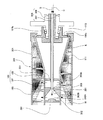
【解決手段】回転軸心廻りに回転して処理対象汚泥を遠心力で分離液Wと脱水ケーキKに固液分離するボウル106と、回転軸心方向でボウル106の他端側に設けた脱水ケーキ排出口113と、ボウル106と同回転軸心廻りに回転してボウル106の内周面上で脱水ケーキKを脱水ケーキ排出口113に向けて移送するスクリューコンベア109Aと、ボウル106に処理対象汚泥を供給する汚泥供給部305と、ボウル106の回転軸心を含む軸心流路316を通して分離液を排出する分離液軸心排出部308を備える。
【選択図】図1Disclosed is a centrifugal dehydrator in which the depth of a discharged liquid of a separation liquid can be made equal to the rotation axis of a bowl.
A bowl 106 that rotates around a rotation axis to separate a sludge to be treated into a separated liquid W and a dehydrated cake K by centrifugal force, and a dehydration provided on the other end side of the bowl 106 in the direction of the rotation axis. The cake discharge port 113, the screw conveyor 109 </ b> A that rotates about the same rotational axis as the bowl 106 and transfers the dewatered cake K toward the dewatered cake discharge port 113 on the inner peripheral surface of the bowl 106, and the bowl 106 to be processed A sludge supply section 305 that supplies sludge and a separation liquid axis discharge section 308 that discharges the separation liquid through an axial flow path 316 including the rotation axis of the bowl 106 are provided.
[Selection] Figure 1
Description
本発明は遠心脱水機および運転方法に関し、汚泥等を高速回転させることで、遠心力を利用して固体と液体に分離させる技術に係るものである。 The present invention relates to a centrifugal dehydrator and an operation method, and relates to a technique for separating sludge and the like into a solid and a liquid using centrifugal force by rotating the sludge at high speed.
従来、例えば下水処理過程で発生する汚泥を処理する装置として、遠心脱水機や遠心濃縮機等の遠心分離機がある。
遠心脱水機は、汚泥を高速回転させることで、汚泥分と水分を比重差によって分離し、脱水するものであり、例えば特許文献1に記載するものがある。
2. Description of the Related Art Conventionally, there are centrifuges such as a centrifugal dehydrator and a centrifugal concentrator as apparatuses for treating sludge generated in a sewage treatment process, for example.
A centrifugal dehydrator rotates a sludge at a high speed to separate a sludge component and moisture by a specific gravity difference, and dehydrates. For example, there is one described in Patent Document 1.
これは図9に示すものであり、遠心脱水機100は、主構造部材101の上に配置する脱水本体部104を軸受け部105a、105bで支持している。
脱水本体部104は、円筒直胴状のボウル106とボウル106の内部に配置する内胴107とを同心状に有し、軸受け部105a、105bがボウル106の回転軸心方向の両端の回転軸部106a、106bを回転可能に支持し、ボウル106が内胴107の回転軸心方向の両端の回転軸部107a、107bを回転可能に支持しており、同心状に配置されたボウル106と内胴107は同じ回転軸心廻りに回転可能である。
This is shown in FIG. 9, and the
The dewatering
内胴107は内胴外周に回転軸心の周りに螺旋状に設けた羽根108を有してスクリューコンベア109を構成している。
ボウル106は回転軸心方向の一端側が主として分離した水分の分離液Wが滞留する分離液領域部110を形成しており、回転軸心方向の他端側が主として分離した汚泥分の脱水ケーキKを移送する脱水ケーキ領域部111を形成している。ボウル106の回転軸心方向の一端側の端部壁110aには複数の分離液排出口112が回転軸心から等距離の位置に、かつ回転軸心廻りに所定間隔で配置されている。
The
The
各分離液排出口112にはダムプレート(堰板)112aが各分離液排出口の開口の一部を覆って装着されている。ボウル106の回転軸心方向の他端側の周壁には複数の脱水ケーキ排出口113が回転軸心を中心とする放射状の位置に、かつ回転軸心廻りに所定間隔で配置されている。
A dam plate (dam plate) 112a is attached to each separation
内胴107とボウル106の間は、脱水ケーキ領域部111がボウル106の他端に近づくほどに狭くなり、内胴107の他端外周面とボウル106の他端内周面との間の隘路106cが脱水ケーキ領域部111と脱水ケーキ排出口113を連通している。
A space between the
脱水本体部104は、内胴107がボウル106に対して所定の差速で回転し、スクリューコンベア109がボウル106の内周面上で脱水ケーキKをボウル106の他端側に向けて移送し、脱水ケーキKが脱水ケーキ領域部111から隘路106cを通して脱水ケーキ排出口113に押し出される。
In the dewatering
脱水本体部104を覆って配置するハウジング114は主構造部材101に固定してあり、分離液領域部110の分離液排出口112を囲む部位に下方に向けて開口する分離液放出口115を有し、脱水ケーキ領域部111の脱水ケーキ排出口113を囲む部位に下方に向けて開口する脱水ケーキ放出口116を有している。
The
軸受け部105bで支持された脱水ケーキ領域部111の側の回転軸部106bおよび回転軸部106bを貫通する内胴107の回転軸107bには差速装置として油圧モータ118を接続し、油圧モータ118に駆動源の駆動モータや油圧ポンプ(図示せず)が連結されている。
A
汚泥供給管120は、軸受け部105aで支持された分離液領域部110の側の回転軸部106aを貫通して内胴107の内部に挿入されており、先端開口120aが内胴107の汚泥投入部121の壁面に対向している。薬剤供給管122は、汚泥供給管120の内部に挿入されており、先端開口122aが内胴107の汚泥投入部121の壁面に対向している。
The
内胴107の汚泥投入部121の周壁には分離液領域部110の内部に向けて開口する複数の汚泥投入口121aが回転軸心を中心とする放射状の位置に、かつ回転軸心廻りに所定間隔で配置されている。
A plurality of
この構成では、原汚泥Sを汚泥供給管120を通して高速回転する内胴107の汚泥投入部121に供給するとともに、高分子凝集剤Cを薬剤供給管122を通して高速回転する内胴107の汚泥投入部121に供給して混合し、原汚泥Sと高分子凝集剤Cの混合汚泥を汚泥投入部121の汚泥投入口121aから高速回転するボウル106の内部に投入する。
In this configuration, the raw sludge S is supplied through the
ボウル106の内部で凝集した汚泥フロックFを含む混合汚泥は、遠心力により分離液Wと脱水ケーキKとに固液分離される。ボウル106と回転数差(差速)をもつスクリューコンベア109が脱水ケーキKを脱水ケーキ領域部111に移送し、脱水ケーキKは脱水ケーキ領域部111を移動する間に含水率がさらに低下し、脱水ケーキ排出口113からハウジング114の内部に排出され、脱水ケーキ放出口116から機外へ放出される。
The mixed sludge including the sludge floc F aggregated inside the
ボウル106の分離液排出口112からダムプレート112aを越流してハウジング114の内部に排出される分離液Wが遠心力を受けて回転軸心廻りに放散されて、分離液放出口115から機外へ放出される。
The separation liquid W that flows over the
また、特許文献2に記載する遠心濃縮機においては、スクリューコンベアの両支持軸を中空とし、その一方の支持軸内を濃縮液の水平排出路とし、他方の支持軸内を分離液の水平排出路として、それぞれ濃縮液および分離液の排出路を構成している。 Moreover, in the centrifugal concentrator described in Patent Document 2, both support shafts of the screw conveyor are hollow, one support shaft is used as a horizontal discharge path for the concentrate, and the other support shaft is discharged horizontally from the separation liquid. As the paths, a concentrated liquid and a separated liquid discharge path are formed.
遠心脱水機は、遠心濃縮機と同様に、遠心力場を形成し、遠心力場において固形分と液体との比重の違いにより、濃縮あるいは脱水する機械である。しかし、固液を分離する脱水と固形分濃度を増加させる濃縮は基本に相違する。 A centrifugal dehydrator is a machine that forms a centrifugal force field and concentrates or dehydrates in the centrifugal field by the difference in specific gravity between the solid content and the liquid in the same manner as the centrifugal concentrator. However, the dehydration for separating the solid and the liquid and the concentration for increasing the solid concentration are basically different.
すなわち、遠心濃縮機では分離液と濃縮液(濃縮汚泥)とに分離し、濃縮液は一般的に固形分が4重量%程度で、水分を90重量%以上含んだ液体状をなす流体であるのに対し、遠心脱水機は分離液と脱水ケーキに分離し、脱水ケーキは固形分濃度が15〜30重量%で、ケーキ含水率が70〜85重量%のほぼ固形物状をなして流動性が乏しいものである。 That is, the centrifugal concentrator separates into a separated liquid and a concentrated liquid (concentrated sludge), and the concentrated liquid is generally a fluid having a solid content of about 4% by weight and containing 90% by weight or more of water. On the other hand, the centrifugal dehydrator separates into a separated liquid and a dehydrated cake, and the dehydrated cake has a solid content of 15 to 30% by weight and a moisture content of the cake of 70 to 85% by weight. Is poor.
したがって、遠心濃縮機において、濃縮液は液体分が多くて流動性があるので、ボウルの回転軸心に対して垂直な方向に延ばした排出路を通して濃縮液をボウルの軸心側から排出することが可能である。しかし、遠心脱水機においては、固形分を多く含む比重の大きな下水汚泥を脱水して水分の少ない固形物(脱水ケーキ)に分離した場合に、流動性の乏しい脱水ケーキを遠心力に抗しながらボウルの軸心側に排出することは困難である。 Therefore, in a centrifugal concentrator, the concentrated liquid has a large liquid content and is fluid, so that the concentrated liquid should be discharged from the axis side of the bowl through a discharge path extending in a direction perpendicular to the rotation axis of the bowl. Is possible. However, in centrifugal dehydrators, when sewage sludge containing a large amount of solids and having a large specific gravity is dehydrated and separated into solids with low water content (dehydrated cake), the dewatered cake with poor fluidity is resisted by centrifugal force. It is difficult to discharge to the axial center side of the bowl.
このため、遠心脱水機の固形物(脱水ケーキ)は、ボウルが直胴型の遠心脱水機やボウルがデカンタ型の遠心脱水機に見られるように、所定の排出半径、つまりボウルの軸心から所定距離の位置に設けた排出口から排出されるのが一般的である。 For this reason, the solid matter (dehydrated cake) of the centrifugal dehydrator is removed from a predetermined discharge radius, that is, the axis of the bowl so that the bowl can be seen in a straight barrel type centrifugal dehydrator or a bowl in a decanter type centrifugal dehydrator. Generally, it is discharged from an outlet provided at a predetermined distance.
そして、ボウル内の内部空間においては、固形物が脱水ケーキ排出口のあるボウルの一端側の脱水ケーキ領域部をほぼ覆って分離液を遮断することで、分離液が脱水ケーキ排出口と反対の他端側の分離液領域部へ追いやられることになる。 In the internal space of the bowl, the solid is almost covered with the dehydrated cake region on one end of the bowl where the dehydrated cake discharge port is located to block the separated liquid, so that the separated liquid is opposite to the dehydrated cake discharge port. It will be driven to the separation liquid region part on the other end side.
分離液排出口は、分離液が脱水ケーキ領域部へ行かないように、脱水ケーキ排出口とほぼ同じ排出半径の位置に設定されており、ボウル内壁面から排出半径までの距離である排出口深さは、一般的には脱水ケーキ領域部側、分離液領域部側において同じとなる。 The separation liquid discharge port is set at the same discharge radius position as the dewatering cake discharge port so that the separation liquid does not go to the dewatering cake area, and the discharge port depth is the distance from the inner wall surface of the bowl to the discharge radius. Generally, this is the same on the dehydrated cake region side and the separation liquid region side.
このように、遠心脱水機においては、ボウルの脱水ケーキ領域部において分離液を遮断する脱水ケーキのケーキ層を形成することが必須である。仮に脱水ケーキ排出口の排出半径に対して分離液排出口の排出半径を小さくして、排出液深をボウル中心側に設定する場合には、分離液の液面が脱水ケーキ領域部に達し、ボウルに供給した処理対象汚泥が十分に固液分離されないままに、脱水ケーキ排出口から流れ出ることになり、脱水ケーキのケーキ層が十分に成長するまで、この状態は改善されず、多量、かつ長時間にわたり処理対象汚泥が十分に固液分離されない状態で排出されることとなる。
したがって、遠心脱水機においては分離液の排出半径を脱水ケーキの排出半径よりも小さくすることは困難であった。
Thus, in the centrifugal dehydrator, it is essential to form a dehydrated cake cake layer that blocks the separated liquid in the dehydrated cake region of the bowl. If the discharge radius of the separation liquid discharge port is made smaller than the discharge radius of the dewatering cake discharge port and the discharge liquid depth is set to the center side of the bowl, the liquid level of the separation liquid reaches the dehydration cake area, The treatment sludge supplied to the bowl will flow out from the dewatered cake discharge port without being sufficiently separated into solid and liquid, and this state will not be improved until the cake layer of the dehydrated cake has grown sufficiently. The sludge to be treated is discharged in a state where the solid-liquid separation is not sufficiently performed over time.
Therefore, in the centrifugal dehydrator, it has been difficult to make the discharge radius of the separated liquid smaller than the discharge radius of the dehydrated cake.
他方、分離液排出口から排出される分離液は、ボウルの回転による遠心加速度を受けて大きな運動エネルギーを伴って排出される。遠心加速度は回転半径の二乗に依存して大きくなるため、分離液の排出半径が大きいほど、遠心加速度の増加によって、分離液の排出に伴って放出される運動エネルギーも大きくなる。このように、分離液の排出半径が大きければ、放出される運動エネルギーが大きくなり、消費電力も大きくなるという問題がある。 On the other hand, the separation liquid discharged from the separation liquid discharge port is discharged with a large kinetic energy in response to centrifugal acceleration caused by the rotation of the bowl. Since the centrifugal acceleration increases depending on the square of the radius of rotation, the larger the discharge radius of the separation liquid, the greater the kinetic energy released along with the discharge of the separation liquid as the centrifugal acceleration increases. Thus, if the discharge radius of the separation liquid is large, there is a problem that the kinetic energy that is released increases and the power consumption also increases.
本発明は上記の課題を解決するものであり、分離液の排出液深をボウルの回転軸心と同等とすることができ、分離液の排出に伴って放出される運動エネルギーを低減し、消費電力を抑制することができる遠心脱水機および運転方法を提供することを目的とする。 The present invention solves the above-described problem, and can make the discharge depth of the separation liquid equal to the rotation axis of the bowl, reducing the kinetic energy released along with the discharge of the separation liquid and consuming it. An object of the present invention is to provide a centrifugal dehydrator and an operation method capable of suppressing electric power.
上記課題を解決するために、本発明の遠心脱水機は、回転軸心廻りに回転して処理対象汚泥を遠心力で分離液と脱水ケーキに固液分離するボウルと、回転軸心方向でボウルの他端側に設けた脱水ケーキ排出口と、ボウルと同回転軸心廻りに回転してボウルの内周面上で脱水ケーキを脱水ケーキ排出口に向けて移送するスクリューコンベアと、ボウルに処理対象汚泥を供給する汚泥供給部と、ボウルの回転軸心を含む軸心流路を通して分離液を排出する分離液軸心排出部を備えることを特徴とする。 In order to solve the above problems, a centrifugal dehydrator according to the present invention includes a bowl that rotates around a rotation axis to separate the sludge to be treated into a separated liquid and a dehydrated cake by centrifugal force, and a bowl in the direction of the rotation axis. The dewatering cake discharge port provided on the other end of the bowl, the screw conveyor that rotates about the same rotation axis as the bowl and transfers the dewatering cake to the dewatering cake discharge port on the inner peripheral surface of the bowl, and the processing to the bowl A sludge supply section for supplying the target sludge and a separation liquid axis discharge section for discharging the separation liquid through an axial flow path including the rotation axis of the bowl are provided.
本発明の遠心脱水機において、分離液軸心排出部は、軸心流路に連通し、スクリューコンベアの回転軸心廻りの外周面に開口する分離液軸心排出口と、ボウルの回転軸心方向の一端側に開口し、分離液をボウルの所定液深で排出する分離液ダム排出口を備えることを特徴とする。 In the centrifugal dehydrator according to the present invention, the separation liquid axis discharge part communicates with the axial flow path, opens to the outer peripheral surface around the rotation axis of the screw conveyor, and the rotation axis of the bowl. It is provided with a separation liquid dam discharge port which opens to one end side in the direction and discharges the separation liquid at a predetermined liquid depth of the bowl.
本発明の遠心脱水機において、分離液軸心排出部は、分離液軸心排出口を通した分離液の排出と分離液ダム排出口を通した分離液の排出とを切り替える排出液深設定部を備えることを特徴とする。 In the centrifugal dehydrator according to the present invention, the separation liquid axis discharge section switches the discharge liquid depth setting section for switching between the discharge of the separation liquid through the separation liquid axis discharge outlet and the discharge of the separation liquid through the separation liquid dam discharge opening. It is characterized by providing.
本発明の遠心脱水機において、排出液深設定部は、分離液ダム排出口における排出液深を漸次に、もしくは段階的に変更する堰高さ変更部を有することを特徴とする。
本発明の遠心脱水機において、分離液軸心排出部は、スクリューコンベアに作用する負荷トルクを指標として排出液深設定部を変更調整することを特徴とする。
In the centrifugal dehydrator according to the present invention, the discharge liquid depth setting section has a weir height changing section that changes the discharge liquid depth at the separation liquid dam discharge port gradually or stepwise.
In the centrifugal dehydrator according to the present invention, the separation liquid axis discharge part changes and adjusts the discharge liquid depth setting part using load torque acting on the screw conveyor as an index.
本発明の遠心脱水機の運転方法は、ボウルを回転軸心廻りに回転させて遠心力でボウル内の処理対象汚泥を分離液と脱水ケーキに固液分離し、分離液がボウルの回転軸心方向の一端側で所定排出半径の位置にある分離液ダム排出口を通して排出される非軸心排水状態から、分離液がボウルの回転軸心を含む軸心流路の分離液軸心排出口を通して排出される軸心排水状態へ遷移させることを特徴とする。 The operation method of the centrifugal dehydrator according to the present invention is such that the bowl is rotated around the rotation axis, and the sludge to be treated in the bowl is solid-liquid separated into a separated liquid and a dehydrated cake by centrifugal force, and the separated liquid is the rotation axis of the bowl. From the non-axial drainage state that is discharged through the separation liquid dam discharge port located at a predetermined discharge radius on one end side in the direction, the separation liquid passes through the separation liquid axis discharge port of the axial flow path including the rotation axis of the bowl. It is characterized by making a transition to the drained axial center state.
以上のように本発明によれば、回転軸心に相応する位置に排出液深を設定し、排出半径を小さくすることで、分離液に与える遠心加速度を低減して排出半径の二乗に依存する運動エネルギーを抑制し、消費動力の低減を図ることができる。 As described above, according to the present invention, the discharge liquid depth is set at a position corresponding to the rotational axis and the discharge radius is reduced, thereby reducing the centrifugal acceleration applied to the separation liquid and depending on the square of the discharge radius. It is possible to suppress kinetic energy and reduce power consumption.
ボウルの回転軸心を含む軸心流路を通して分離液を排出することで、分離液の排出液深がボウルの回転軸心に相応するものとなり、分離液の清澄度が大きくなる。
また、排出液深設定部によって、分離液軸心排出口を通した分離液の排出と、分離液ダム排出口を通した分離液の排出とを切り替えることで、運転初期時に分離液ダム排出口を通して低い液深下で分離液を排出し、脱水ケーキ排出口に対して分離液を遮断する脱水ケーキのケーキ層を確実に形成することができる。このため、分離液軸心排出口を通した分離液の排出を行うまでの間に、ボウルに供給した処理対象汚泥が十分に固液分離されないままに、脱水ケーキ排出口から流れ出ることを防止できる。
By discharging the separation liquid through the axial flow path including the rotation axis of the bowl, the discharge depth of the separation liquid corresponds to the rotation axis of the bowl, and the clarity of the separation liquid is increased.
Also, the separation liquid dam discharge port is switched at the initial stage of operation by switching the separation liquid discharge through the separation liquid axial discharge port and the separation liquid discharge through the separation liquid dam discharge port by the discharge liquid depth setting unit. Thus, a cake layer of a dehydrated cake that discharges the separated solution at a low liquid depth and blocks the separated solution from the dehydrated cake discharge port can be formed reliably. For this reason, it is possible to prevent the treatment target sludge supplied to the bowl from flowing out from the dewatered cake discharge port without being sufficiently solid-liquid separated until the separation liquid is discharged through the separation liquid shaft discharge port. .
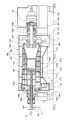
本発明の実施の形態を図面に基づいて説明する。図1、図2および図3において、先に図7で説明した構成部材と同作用のものは同符号を付して説明を省略する。
本実施の形態の遠心脱水機300は、ボウル106が回転軸心方向の両端に設けた回転軸部106a、106bを軸受け部105a、105bに支承されて、回転軸部106a、106bの回転軸心廻りに回転し、ボウル106が内胴107の回転軸心方向の両端の回転軸部107a、107bを回転可能に支持し、同心状に配置されたボウル106と内胴107は同じ回転軸心廻りに回転し、処理対象汚泥を遠心力で分離液と脱水ケーキに固液分離する。
Embodiments of the present invention will be described with reference to the drawings. 1, 2, and 3, the same components as those described in FIG. 7 are given the same reference numerals and description thereof is omitted.
In the
ボウル106は、回転軸心方向でボウル106の一端側に分離液ダム排出口112を有し、他端側に脱水ケーキ排出口113を有している。スクリューコンベア109は、回転軸心方向に沿って延びる内胴107と、内胴外周に螺旋状に設けられて脱水ケーキを掻き寄せる羽根108を有しており、内部を複数の隔壁301で仕切って汚泥投入部302、凝集剤投入部303、分離液排出部304を形成している。内胴107の外周面には、汚泥投入部302の汚泥投入口302A、および凝集剤投入部303の凝集剤投入口303Aが開口している。
The
ボウル106に処理対象汚泥を供給する汚泥供給部305は、ボウル106の他端側から内胴107に挿入する二重管からなり、処理対象汚泥を供給する内管306が汚泥投入部302で開口し、凝集剤を供給する外管307が凝集剤投入部303で開口している。汚泥投入部302にはテーパ状に拡径する汚泥ガイド部302Bを設けており、内管306を通して汚泥投入部302に供給した処理対象汚泥が汚泥ガイド部302Bに沿って広がり、汚泥投入口302Aからボウル106内に投入され、外管307を通して凝集剤投入部303に供給した凝集剤が凝集剤投入口303Aからボウル106内に投入される。
The
本実施の形態では汚泥投入部302および凝集剤投入部303を分けて設けているが、汚泥投入部302と凝集剤投入部303を一つの領域に形成し、処理対象汚泥と凝集剤を内胴107の同じ領域に投入した後にボウル106に供給することも可能であり、凝集剤を供給する構成には任意の態様を採用することができる。また、凝集剤は無機凝集剤、高分子凝集剤の何れであっても良い。
In this embodiment, the
本実施の形態では、内胴107を回転軸心方向に貫通して汚泥供給部305を配置し、汚泥供給部305の基端側を固定部材(図示省略)で固定支持し、貫通部において汚泥供給部305と内胴107Aの間をシールするシール手段(図示省略)を設けている。
In the present embodiment, the
しかし、図4に示すように汚泥供給部305を内胴107に溶接固定し、汚泥供給部305と内胴107を一体に回転させることも可能である。この場合には、汚泥供給部305の基端側に回転継手(図示省略)を設けて処理対象汚泥および凝集剤を供給する。
However, as shown in FIG. 4, the
ボウル106の一端側には、ボウル106の回転軸心を含む軸心流路316を形成する軸心流路管317を通して分離液を排出する分離液軸心排出部308を備えている。
分離液軸心排出部308は、軸心流路316に連通し、スクリューコンベア109の内胴107の回転軸心廻りの外周面に開口する分離液軸心排出口309と、分離液ダム排出口112とを切り替える排出液深設定部310を備えている。
One end of the
The separation liquid
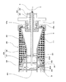
排出液深設定部310には、軸心流路管317と同心状に配置した液深変更部311を回転自在に配置している。液深変更部311は、図1に示すように、分離液ダム排出口112を開放する開放部311Aと、図2に示すように、分離液ダム排出口112を閉鎖する閉鎖部311Bを有し、ボウル106と同期して回転し、かつ開放部311Aが分離液ダム排出口112に対応する位置と、閉鎖部311Bが分離液ダム排出口112に対応する位置とにわたって、ボウル106に対して相対的に回転可能である。
In the discharge liquid
閉鎖部311Bは、分離液ダム排出口112における排出液深を漸次に、もしくは段階的に変更する堰高さ変更部に形成することも可能である。
分離液軸心排出部308の排出液深設定部310は、本実施の形態では、スクリューコンベア109に作用する実負荷運転時の負荷トルクを指標として変更調整する。しかし、分離液軸心排出部308の排出液深設定部310を変更調整する指標には、前記の負荷トルクの他に、例えばタイマーで計測する稼働時間を採用することも可能である。
The
In the present embodiment, the discharge liquid
分離液ダム排出口112はダム排出口バルブ312aを介して分離液排出系313に連通し、軸心流路管317は回転継手318および軸心流路バルブ312bを介して分離液排出系313に連通している。ダム排出口バルブ312a、軸心流路バルブ312bは必ずしも設ける必要はなく、何れか一方を設けることも可能である。
The separation liquid
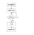
この構成によれば、図1、図5および図6に示すように、脱水機運転を開始し、実負荷運転初期時においては、液深変更部311の開放部311Aを分離液ダム排出口112に対応させて運転し、ダム排出口バルブ312aを開放し、軸心流路バルブ312bを閉鎖し、分離液ダム排出口112を通して低い排出液深D1で分離液を排出し、分離液を分離液排出系313を通して外部に排出する。
According to this configuration, as shown in FIGS. 1, 5, and 6, the dehydrator operation is started, and at the initial stage of the actual load operation, the
次に、脱水ケーキKによりスクリューコンベア109に作用する負荷トルクを指標として脱水ケーキ領域部111の脱水ケーキKのケーキ堆積状況を監視し、スクリューコンベア109に作用する負荷トルクが所定値Tcを超えた時に、脱水ケーキKのケーキ層が所定量に達し、脱水ケーキ領域部111において脱水ケーキ排出口113Aに対して分離液Wを遮断できる状態に遷移したと判断する。
Next, the cake accumulation state of the dewatered cake K in the dewatered
そして、図2に示すように、排出液深設定部310の液深変更部311を操作し、閉鎖部311Bを分離液ダム排出口112に対応させることで、分離液ダム排出口112を閉鎖し、ダム排出口バルブ312aを閉鎖し、軸心流路バルブ312bを開放する。
Then, as shown in FIG. 2, the liquid
ボウル106の内部で分離液Wの液位が増加し、分離液Wが分離液軸心排出口309を通して内胴107の分離液排出部304に流入し、軸心流路管307を通して高い排出液深Dcで分離液を軸心排水する状態に移行し、分離液を軸心流路管317、軸心流路バルブ312bおよび分離液排出系313を通して外部に排出する。
The liquid level of the separation liquid W increases in the
このとき、バルブ312の開度を調整して分離液の排出流量を制御することにより、軸心流路管317における排出液深を調整でき、分離液が軸心流路管317を満たす満管状態を維持して分離液の排出を行うことも可能であり、軸心流路管317の内周面に相応する排出液深で分離液を排出することも可能である。
At this time, by adjusting the opening degree of the valve 312 to control the discharge flow rate of the separation liquid, the discharge liquid depth in the axial
このように、ボウル106の回転軸心を含む軸心流路316を通して分離液を排出することで、分離液の排出液深がボウル106の回転軸心に相応するものとなり、分離液の清澄度が大きくなり、脱水ケーキに移行する処理対象汚泥中の固形分が多くなり、濃縮効率が向上し、消費エネルギーを抑制できる。
Thus, by discharging the separation liquid through the
また、運転初期には、分離液ダム排出口112を通して分離液を排出することで、処理対象汚泥が脱水ケーキ排出口113から流れ出ることを防止できる。他の作用効果は先の実施の形態および図9で説明したものと同様である。
In addition, at the initial stage of operation, the separation liquid is discharged through the separation liquid
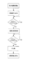
本実施の形態では、排出液深設定部311の開放部311Aと閉鎖部311Bと二者選択的に切り替える構成を示したが、上述したように、排出液深設定部311が分離液ダム排出口112における排出液深を漸次に、もしくは段階的に変更する堰高さ変更部に形成する場合には、脱水ケーキKによりスクリューコンベア109に作用する負荷トルクを指標として排出液深を漸次に、もしくは段階的に調節することも可能である。
In the present embodiment, the configuration in which the
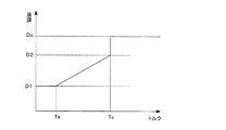
すなわち、図7および図8に示すように、脱水機運転を開始し、実負荷運転初期時においては、液深変更部311の開放部311Aを分離液ダム排出口112に対応させて運転し、ダム排出口バルブ312aを開放し、軸心流路バルブ312bを閉鎖し、分離液ダム排出口112を通して低い排出液深D1で分離液を排出し、分離液を分離液排出系313を通して外部に排出する。
That is, as shown in FIG. 7 and FIG. 8, the dehydrator operation is started, and at the initial stage of the actual load operation, the
次に、脱水ケーキKによりスクリューコンベア109に作用する負荷トルクを指標として脱水ケーキ領域部111の脱水ケーキKのケーキ堆積状況を監視し、スクリューコンベア109に作用する負荷トルクが所定値Tsを超えた時に、排出液深設定部311により分離液ダム排出口112における堰高さを変更制御して排出液深を増加させる。そして、スクリューコンベア109に作用する負荷トルクが所定値Tcを超えた時に、脱水ケーキKのケーキ層が所定量に達し、液深が高位の排出液深D2となり、脱水ケーキ領域部111において脱水ケーキ排出口113Aに対して分離液Wを遮断できる状態に遷移したと判断する。
Next, the cake accumulation state of the dewatered cake K in the dewatered
そして、液深変更部311を操作して分離液ダム排出口112を閉鎖し、ダム排出口バルブ312aを閉鎖し、軸心流路バルブ312bを開放する。
ボウル106の内部で分離液Wの液位が増加し、分離液Wが分離液軸心排出口309を通して内胴107の分離液排出部304に流入し、軸心流路管307を通して高い排出液深Dcで分離液を軸心排水する状態に移行し、分離液を軸心流路管317、軸心流路バルブ312bおよび分離液排出系313を通して外部に排出する。
Then, the liquid
The liquid level of the separation liquid W increases in the
本実施の形態においては、直胴型のボウルを有する遠心脱水機を例示して説明したが、本発明はデカンタ型のボウルを有する遠心脱水機などのあらゆるタイプの遠心脱水機に適用可能である。また、本実施の形態で説明した他の細部に関しても本発明の範囲内で適宜に変更可能である。 In the present embodiment, the centrifugal dehydrator having a straight barrel type bowl has been described as an example, but the present invention is applicable to all types of centrifugal dehydrators such as a centrifugal dehydrator having a decanter type bowl. . Further, other details described in the present embodiment can be appropriately changed within the scope of the present invention.
300 遠心脱水機
105a、105b 軸受け部
106 ボウル
106a、106b 回転軸部
106c 隘路
107 内胴
107a、107b 回転軸部
108 羽根
109 スクリューコンベア
110 分離液領域部
110a 端部壁
111 脱水ケーキ領域部
112 分離液ダム排出口
113 脱水ケーキ排出口
301 隔壁
302 汚泥投入部
302A 汚泥投入口
302B 汚泥ガイド部
303 凝集剤投入部
303A 凝集剤投入口
304 分離液排出部
305 汚泥供給部
306 内管
307 外管
308 分離液軸心排出部
309 分離液軸心排出口
310 排出液深設定部
311 液深変更部
311A 開放部
311B 閉鎖部
312a ダム排出口バルブ
312b 軸心流路バルブ
313 分離液排出系
316 軸心流路
317 軸心流路管
318 回転継手
C 高分子凝集剤
S 原汚泥
W 分離液
K 脱水ケーキ
300 Centrifugal dehydrator 105a,
Claims (6)
The bowl is rotated around the rotation axis, and the sludge to be treated in the bowl is solid-liquid separated into a separated liquid and a dehydrated cake by centrifugal force, and the separated liquid is positioned at a predetermined discharge radius at one end side in the direction of the rotation axis of the bowl. Transition from a non-axial drainage state that is discharged through a certain separation liquid dam discharge port to a central drainage state in which the separation liquid is discharged through the separation liquid axis discharge port of the axial flow path including the rotation axis of the bowl. The operation method of the centrifugal dehydrator characterized by this.
Priority Applications (1)
| Application Number | Priority Date | Filing Date | Title |
|---|---|---|---|
| JP2016085759A JP6700934B2 (en) | 2016-04-22 | 2016-04-22 | Centrifugal dehydrator and operating method |
Applications Claiming Priority (1)
| Application Number | Priority Date | Filing Date | Title |
|---|---|---|---|
| JP2016085759A JP6700934B2 (en) | 2016-04-22 | 2016-04-22 | Centrifugal dehydrator and operating method |
Publications (2)
| Publication Number | Publication Date |
|---|---|
| JP2017192910A true JP2017192910A (en) | 2017-10-26 |
| JP6700934B2 JP6700934B2 (en) | 2020-05-27 |
Family
ID=60155290
Family Applications (1)
| Application Number | Title | Priority Date | Filing Date |
|---|---|---|---|
| JP2016085759A Active JP6700934B2 (en) | 2016-04-22 | 2016-04-22 | Centrifugal dehydrator and operating method |
Country Status (1)
| Country | Link |
|---|---|
| JP (1) | JP6700934B2 (en) |
Cited By (3)
| Publication number | Priority date | Publication date | Assignee | Title |
|---|---|---|---|---|
| CN114292002A (en) * | 2022-01-10 | 2022-04-08 | 江苏环保产业技术研究院股份公司 | Environment-friendly sewage treatment plant uses sludge treatment equipment |
| JP2022155605A (en) * | 2021-03-31 | 2022-10-14 | 株式会社クボタ | Centrifugal dehydrator and centrifugal dehydration processing method of slurry containing organic solid |
| CN117383785A (en) * | 2023-12-08 | 2024-01-12 | 苏州惠新普环保科技有限公司 | Centrifugal separation device for energy-saving river sludge treatment |
-
2016
- 2016-04-22 JP JP2016085759A patent/JP6700934B2/en active Active
Cited By (5)
| Publication number | Priority date | Publication date | Assignee | Title |
|---|---|---|---|---|
| JP2022155605A (en) * | 2021-03-31 | 2022-10-14 | 株式会社クボタ | Centrifugal dehydrator and centrifugal dehydration processing method of slurry containing organic solid |
| JP7621159B2 (en) | 2021-03-31 | 2025-01-24 | 株式会社クボタ | Centrifugal dehydrator and method for centrifugal dehydration of slurry containing organic solids |
| CN114292002A (en) * | 2022-01-10 | 2022-04-08 | 江苏环保产业技术研究院股份公司 | Environment-friendly sewage treatment plant uses sludge treatment equipment |
| CN117383785A (en) * | 2023-12-08 | 2024-01-12 | 苏州惠新普环保科技有限公司 | Centrifugal separation device for energy-saving river sludge treatment |
| CN117383785B (en) * | 2023-12-08 | 2024-02-27 | 苏州惠新普环保科技有限公司 | Centrifugal separation device for energy-saving river sludge treatment |
Also Published As
| Publication number | Publication date |
|---|---|
| JP6700934B2 (en) | 2020-05-27 |
Similar Documents
| Publication | Publication Date | Title |
|---|---|---|
| US4898571A (en) | Solid bowl centrifuge | |
| JP6751564B2 (en) | centrifuge | |
| JP2020097027A (en) | centrifuge | |
| CN103415348A (en) | Centrifugal dehydration method and centrifugal dehydration device | |
| JP6700934B2 (en) | Centrifugal dehydrator and operating method | |
| JP6619247B2 (en) | centrifuge | |
| JPH04193363A (en) | Decanter type centrifugal separator | |
| CA2942707C (en) | Decanter centrifuge with double axial sealing | |
| CN118524893A (en) | Non-porous drum centrifuge and method for regulating the separation process of a non-porous drum centrifuge | |
| KR100787470B1 (en) | Three-Phase Centrifuge with Eccentric Dam Control | |
| KR20020073545A (en) | Centrifugal separator | |
| JP4322513B2 (en) | Decanter type centrifugal dehydration apparatus and centrifugal dehydration method using the apparatus | |
| JPH07246349A (en) | Separation plate type centrifuge | |
| FI65766B (en) | CENTRIFUG MED TVAO CONCENTRATE TRUMMOR FOR AVVATTNING AV SLAM | |
| US12290824B2 (en) | Solid bowl screw centrifuge with mixing blades or paddles arranged on the screw shaft | |
| KR20110096881A (en) | Vertical Centrifuge | |
| JP6230240B2 (en) | centrifuge | |
| JPH07284693A (en) | Separating plate type centrifugal machine | |
| KR101590061B1 (en) | a 4 phase Centrifuge | |
| JP2022120224A (en) | centrifuge | |
| KR100427045B1 (en) | Apparatus to dehydrate sludge of centrifugal separation type | |
| JP3974066B2 (en) | Decanter type centrifugal dehydrator | |
| CN223010800U (en) | A horizontal screw centrifuge with a liquid discharge structure | |
| CN214107470U (en) | Sludge dewatering centrifuge of variable direction speed governing | |
| KR19990083738A (en) | Horizontal series-type double acceleration centrifugal |
Legal Events
| Date | Code | Title | Description |
|---|---|---|---|
| A621 | Written request for application examination |
Free format text: JAPANESE INTERMEDIATE CODE: A621 Effective date: 20181217 |
|
| A131 | Notification of reasons for refusal |
Free format text: JAPANESE INTERMEDIATE CODE: A131 Effective date: 20191001 |
|
| A977 | Report on retrieval |
Free format text: JAPANESE INTERMEDIATE CODE: A971007 Effective date: 20190930 |
|
| A521 | Written amendment |
Free format text: JAPANESE INTERMEDIATE CODE: A523 Effective date: 20191125 |
|
| TRDD | Decision of grant or rejection written | ||
| A01 | Written decision to grant a patent or to grant a registration (utility model) |
Free format text: JAPANESE INTERMEDIATE CODE: A01 Effective date: 20200407 |
|
| A61 | First payment of annual fees (during grant procedure) |
Free format text: JAPANESE INTERMEDIATE CODE: A61 Effective date: 20200501 |
|
| R150 | Certificate of patent or registration of utility model |
Ref document number: 6700934 Country of ref document: JP Free format text: JAPANESE INTERMEDIATE CODE: R150 |