JP2017192934A - Waste water treatment method - Google Patents
Waste water treatment method Download PDFInfo
- Publication number
- JP2017192934A JP2017192934A JP2017075739A JP2017075739A JP2017192934A JP 2017192934 A JP2017192934 A JP 2017192934A JP 2017075739 A JP2017075739 A JP 2017075739A JP 2017075739 A JP2017075739 A JP 2017075739A JP 2017192934 A JP2017192934 A JP 2017192934A
- Authority
- JP
- Japan
- Prior art keywords
- tank
- nitrification tank
- nitrification
- denitrification
- concentration
- Prior art date
- Legal status (The legal status is an assumption and is not a legal conclusion. Google has not performed a legal analysis and makes no representation as to the accuracy of the status listed.)
- Granted
Links
Images


Landscapes
- Purification Treatments By Anaerobic Or Anaerobic And Aerobic Bacteria Or Animals (AREA)
Abstract
Description
本発明は、最終処分場浸出水処理施設、し尿処理施設、産業廃水処理施設等の溶解性蒸発残留物および/またはカリウムイオン濃度が高い廃水を対象に生物学的硝化脱窒処理する方法に係わり、硝化槽のアンモニア濃度をアンモニウムイオン電極で測定し、硝化槽への酸素含有気体供給量の制御を行う廃水処理方法に関するものである。 The present invention relates to a method for biological nitrification denitrification treatment of soluble evaporation residue and / or wastewater with high potassium ion concentration, such as leachate treatment facility, human waste treatment facility, industrial wastewater treatment facility, etc. Further, the present invention relates to a wastewater treatment method in which the ammonia concentration in a nitrification tank is measured with an ammonium ion electrode, and the oxygen-containing gas supply amount to the nitrification tank is controlled.
従来より、生物学的硝化脱窒素法の硝化反応の制御としては、硝化反応を行う生物反応槽(以下、硝化槽とも記す)のDO(溶存酸素)制御およびpH制御が使用されていた。そして近年、下水処理では、硝化反応の制御としてアンモニウムイオン電極(アンモニアセンサー、NH4センサー、NH4計、アンモニア計ともいう)の導入が進みつつある。 Conventionally, DO (dissolved oxygen) control and pH control of a biological reaction tank (hereinafter also referred to as a nitrification tank) for performing a nitrification reaction have been used as a control of a nitrification reaction in a biological nitrification denitrification method. In recent years, in sewage treatment, the introduction of ammonium ion electrodes (also referred to as ammonia sensors, NH 4 sensors, NH 4 meters, and ammonia meters) is being advanced as a control for nitrification reactions.
特許文献1や特許文献2では下水処理場での硝化脱窒素処理を対象とし、アンモニアセンサー等を用い、気体供給量等を制御する方法が記載されている。また特許文献3では、微生物フロックに紫外線を照射することで微生物が発生する生物蛍光体の蛍光量を測定する蛍光測定センサーにより送風量を制御する方法が記載されており、補助センサーとしてアンモニア濃度を測定するアンモニアセンサーを用いている。 Patent Literature 1 and Patent Literature 2 describe a method of controlling a gas supply amount and the like using an ammonia sensor or the like for nitrification denitrification treatment at a sewage treatment plant. Patent Document 3 describes a method of controlling the amount of air blown with a fluorescence measurement sensor that measures the fluorescence amount of a biophosphor generated by microorganisms by irradiating the microorganism floc with ultraviolet rays. An ammonia sensor to measure is used.
また非特許文献1では、下水処理での空気量制御にNOX-N計とNH4-N計を使用する方法であり、深槽曝気槽好気部での硝化脱窒同時処理についての記載がある。また非特許文献2では、下水処理における空気量制御にNH4-N計を使用し、好気槽での硝化脱窒同時処理、硝化内生脱窒法でのNH4-N最適値の存在、空気量制御手法としての、DO制御に対するNH4-N制御の優位性についての記載がある。また非特許文献3では、し尿の脱水ろ液を7倍希釈後に下水と混合して受け入れているOD法の処理場において、自動測定器としてアンモニア性窒素、硝酸性窒素、カリウムのイオンセンサーを設置し、運転データを可視化することでの処理状況が改善された事例について報告されている。 Non-Patent Document 1 describes a method of using an NO X -N meter and an NH 4 -N meter for air amount control in sewage treatment, and a description of simultaneous nitrification and denitrification in an aerobic part of a deep tank aeration tank. There is. The Non-Patent Document 2, by using the NH 4 -N meter air amount control in sewage treatment, the presence of nitrification窒同during treatment, NH 4 -N optimum value in the nitrification endogenous denitrification in aerobic tank, There is a description of the superiority of NH 4 -N control over DO control as an air amount control method. In Non-Patent Document 3, an ion sensor for ammonia nitrogen, nitrate nitrogen, and potassium is installed as an automatic measuring instrument in an OD method treatment plant that accepts mixed dehydrated filtrate of human waste after sevenfold dilution with sewage. However, there have been reports of cases where the processing status has been improved by visualizing operation data.
上述のように、生物学的硝化脱窒素法の硝化反応の制御としては、硝化槽DO制御およびpH制御が使用されていた。しかし、DO制御やpH制御ではアンモニア性窒素濃度を把握できないため、硝化槽に十分な空気を供給し、DO濃度を2mg/L程度の高めに設定することで、硝化菌の作用によりほぼ全てのアンモニア性窒素を硝酸性窒素へと転換していた。そのため、硝化槽では多大な空気量が必要となっていた。 As described above, the nitrification tank DO control and pH control were used as the control of the nitrification reaction in the biological nitrification denitrification method. However, since the ammonia nitrogen concentration cannot be grasped by DO control or pH control, by supplying sufficient air to the nitrification tank and setting the DO concentration to a high level of about 2 mg / L, almost all of the nitrifying bacteria can function. Ammonia nitrogen was converted to nitrate nitrogen. Therefore, a great amount of air is required in the nitrification tank.
下水処理では、この問題点を改善するために、NH4センサーの採用が進みつつあるが、最終処分場浸出水処理施設、し尿処理施設、産業廃水処理施設等で処理対象となる溶解性蒸発残留物および/またはカリウムイオン濃度が高い廃水の場合では、共存イオンおよび/またはカリウムイオンの影響でNH4センサーの適用は困難であり、また、溶解性蒸発残留物および/またはカリウムイオン濃度が高い廃水に適用できるNH4センサーの報告例は無い。 In sewage treatment, NH 4 sensors are being adopted to remedy this problem, but soluble evaporative residues that are to be treated at the final disposal site leachate treatment facility, human waste treatment facility, industrial wastewater treatment facility, etc. In the case of wastewater with a high concentration of substances and / or potassium ions, it is difficult to apply the NH 4 sensor due to the influence of coexisting ions and / or potassium ions, and wastewater with a high concentration of soluble evaporation residue and / or potassium ions There is no report of NH 4 sensor applicable to.
本発明は、溶解性蒸発残留物および/またはカリウムイオン濃度が高い廃水に対しても、アンモニア濃度を正確に測定でき、硝化槽のDO値を過度に高めることなく、安定した硝化反応の進行と、硝化脱窒同時進行が生じ、窒素除去・濃度低減効果を高めることができる廃水処理方法の提供を目的とする。 The present invention is capable of accurately measuring ammonia concentration even for waste water having a high concentration of soluble evaporation residue and / or potassium ion, and without increasing the DO value of the nitrification tank excessively, The purpose of the present invention is to provide a wastewater treatment method in which simultaneous nitrification and denitrification can occur and the effect of nitrogen removal and concentration reduction can be enhanced.
本発明にかかる廃水処理方法は、溶解性蒸発残留物および/またはカリウムイオン濃度が高い廃水を生物学的硝化脱窒処理する廃水処理方法において、硝化槽のアンモニア濃度を測定する液体分析計として、液絡部を介して外部と連通する空間内に内部液である塩化カリウム飽和液と当該内部液に接触する内部極であるAg/AgCl電極とを備えた比較電極と、応答膜によって外部から仕切られた空間内に内部液として塩化アンモニウム水溶液と当該内部液に接触する内部極としてAg/AgCl電極とを備えたアンモニウムイオン電極とを具備する構成の液体分析計を用い、前記液体分析計により測定した硝化槽のアンモニア濃度に応じて、硝化槽への酸素含有気体供給量を制御することを特徴としている。
なお、測定対象のアンモニウムイオンの測定可能な濃度範囲は、前記比較電極の内部液中の塩化物イオン濃度よりも低いことが好ましい。また、前記アンモニウムイオン電極の内部液は、アンモニウムイオンと塩化物イオンとを含有しており、前記アンモニウムイオン電極の内部液は、前記アンモニウムイオン電極の内部液の浸透圧と等温交点とが所望の値になり、かつ、当該等温交点が前記測定可能な濃度範囲内に含まれているように、前記アンモニウムイオン電極の内部液中のアンモニウムイオンの濃度と塩素イオンの濃度が調整されたものであり、当該塩素イオンの濃度が、前記比較電極の内部液中の塩素イオンの濃度とは異なっていることが好ましい。
上記本発明にかかる液体分析計によれば、溶解性蒸発残留物および/またはカリウムイオン濃度が高い廃水に対しても、共存イオンおよび/またはカリウムイオンの影響を受けずにアンモニア濃度を正確に測定することができることを実験によって確認した。このため、硝化槽に対する酸素含有気体の供給量を硝化槽のNH4濃度に応じて正確に制御することが可能になる。
そして、硝化槽のNH4濃度に応じて酸素含有気体の供給量を制御することで、従来のように硝化槽のDO値を高める必要が無くなる。即ち、例えば硝化槽のDO値を1mg/L以下と、従来よりも低く保つことが可能となり、硝化槽において安定した硝化反応の進行が図れ、また硝化槽での硝化脱窒同時進行が生じ、窒素除去濃度低減効果を高めることが可能となる。
The wastewater treatment method according to the present invention is a liquid analyzer for measuring ammonia concentration in a nitrification tank in a wastewater treatment method for biologically nitrifying and denitrifying wastewater having a high soluble evaporation residue and / or high potassium ion concentration. A reference electrode having a potassium chloride saturated liquid as an internal liquid and an Ag / AgCl electrode as an internal electrode in contact with the internal liquid in a space communicating with the outside through a liquid junction, and is partitioned from the outside by a response film Measured with the liquid analyzer using an aqueous solution of ammonium chloride as an internal liquid and an ammonium ion electrode having an Ag / AgCl electrode as an internal electrode in contact with the internal liquid. The oxygen-containing gas supply amount to the nitrification tank is controlled according to the ammonia concentration in the nitrification tank.
Note that the measurable concentration range of ammonium ions to be measured is preferably lower than the chloride ion concentration in the internal solution of the reference electrode. The internal solution of the ammonium ion electrode contains ammonium ions and chloride ions, and the internal solution of the ammonium ion electrode is desired to have an osmotic pressure and an isothermal intersection of the internal solution of the ammonium ion electrode. And the concentration of ammonium ions and the concentration of chloride ions in the internal liquid of the ammonium ion electrode are adjusted so that the isothermal intersection is within the measurable concentration range. The chlorine ion concentration is preferably different from the chlorine ion concentration in the internal liquid of the reference electrode.
According to the liquid analyzer according to the present invention, the ammonia concentration can be accurately measured without being influenced by the coexisting ions and / or potassium ions even in the waste water having high solubility of soluble evaporation residues and / or potassium ions. It was confirmed by experiment that it can be done. For this reason, the supply amount of the oxygen-containing gas to the nitrification tank can be accurately controlled according to the NH 4 concentration in the nitrification tank.
Then, by controlling the supply amount of the oxygen-containing gas according to the NH 4 concentration in the nitrification tank, there is no need to increase the DO value of the nitrification tank as in the prior art. That is, for example, the DO value of the nitrification tank can be kept at 1 mg / L or less, which is lower than the conventional one, and the stable nitrification reaction can proceed in the nitrification tank, and the simultaneous nitrification and denitrification progress in the nitrification tank occurs. It is possible to increase the nitrogen removal concentration reduction effect.
また本発明は、前記硝化槽のDO値が所定値以下になるように制御することによって、硝化槽において硝化反応と脱窒素反応を同時に進行させることを特徴としている。 Further, the present invention is characterized in that the nitrification reaction and the denitrification reaction are simultaneously advanced in the nitrification tank by controlling the DO value of the nitrification tank to be a predetermined value or less.
また本発明は、前記硝化槽のDO値が所定値以下になるように、前記硝化槽への廃水の流入水量を調整することを特徴としている。 Further, the present invention is characterized in that the amount of waste water flowing into the nitrification tank is adjusted so that the DO value of the nitrification tank is not more than a predetermined value.
また本発明は、前記硝化槽のDO値が所定値以下になるように前記硝化槽のNH4-N設定値を設定し、その設定値となるように、前記硝化槽への酸素含有気体供給量を制御することを特徴としている。 Further, the present invention sets the NH 4 -N set value of the nitrification tank so that the DO value of the nitrification tank is a predetermined value or less, and supplies the oxygen-containing gas to the nitrification tank so as to be the set value. It is characterized by controlling the amount.
また本発明は、前記所定値が1mg/Lであることを特徴としている。硝化槽のDO値を1mg/L以下となるようにすることで、硝化槽でのより効果的な硝化脱窒同時進行が生じ、窒素除去濃度低減効果を高めることができる。 Further, the present invention is characterized in that the predetermined value is 1 mg / L. By setting the DO value of the nitrification tank to 1 mg / L or less, more effective simultaneous nitrification denitrification in the nitrification tank occurs, and the nitrogen removal concentration reduction effect can be enhanced.
また本発明は、溶解性蒸発残留物および/またはカリウムイオン濃度が高い廃水を、少なくとも、脱窒素槽から、硝化槽、二次脱窒素槽、再曝気槽に導入することで生物学的硝化脱窒素処理を行う廃水処理方法において、前記硝化槽で測定したアンモニア濃度に応じて、当該硝化槽への酸素含有気体供給量を制御すると共に、前記硝化槽内のDO値が所定値以下になるように制御することによって、硝化槽における硝化反応と脱窒素反応を同時に進行させることを特徴としている。
硝化槽のNH4濃度に応じて酸素含有気体の供給量を制御することで、従来のように硝化槽のDO値を高める必要が無くなる。即ち、硝化槽のDO値を従来よりも低く保つことが可能となり、硝化槽において安定した硝化反応の進行が図れ、また硝化槽での硝化脱窒同時進行が生じ、窒素除去濃度低減効果を高めることが可能となる。
The present invention also provides biological nitrification / denitrification by introducing at least a soluble evaporation residue and / or wastewater having a high potassium ion concentration from a denitrification tank to a nitrification tank, a secondary denitrification tank, and a re-aeration tank. In the wastewater treatment method in which nitrogen treatment is performed, according to the ammonia concentration measured in the nitrification tank, the oxygen-containing gas supply amount to the nitrification tank is controlled, and the DO value in the nitrification tank is set to a predetermined value or less. It is characterized by simultaneously controlling the nitrification reaction and the denitrification reaction in the nitrification tank.
By controlling the supply amount of the oxygen-containing gas according to the NH 4 concentration in the nitrification tank, it is not necessary to increase the DO value of the nitrification tank as in the conventional case. In other words, it becomes possible to keep the DO value of the nitrification tank lower than before, so that the nitrification reaction can proceed stably in the nitrification tank, and the nitrification denitrification progresses simultaneously in the nitrification tank, thereby enhancing the nitrogen removal concentration reduction effect. It becomes possible.
また本発明は、前記硝化槽を機能的に複数に分割し、分割した硝化槽前半部分で、測定したアンモニア濃度に応じて硝化槽前半部分への酸素含有気体供給量を制御すると共に、DO値が所定値以下になるように制御し、一方、分割した硝化槽後半部分で、DO値が前記所定値以上になるように制御して硝化槽前半部分に残留したNH4-NをNOX-Nに消化することを特徴としている。これによって、放流水のNH4-N+NOX-N値を小さくでき、さらに良好な窒素除去を達成することができる。 Further, the present invention functionally divides the nitrification tank into a plurality of parts, and controls the oxygen-containing gas supply amount to the first half of the nitrification tank according to the measured ammonia concentration in the divided first nitrification tank, and the DO value. The NH 4 -N remaining in the first half of the nitrification tank by controlling the DO value to be equal to or higher than the predetermined value in the latter half of the nitrification tank is controlled to be NO X- It is characterized by digestion into N. As a result, the NH 4 —N + NO X —N value of the effluent water can be reduced, and better nitrogen removal can be achieved.
本発明によれば、溶解性蒸発残留物および/またはカリウムイオン濃度が高い廃水に対しても、共存イオンおよび/またはカリウムイオンの影響を受けずにアンモニア濃度を正確に測定でき、従来のように硝化槽のDO値を過度に高めることが無く、硝化槽における安定した硝化反応の進行と、硝化槽での硝化脱窒同時進行が生じ、窒素除去・濃度低減効果を高めることができる。 According to the present invention, it is possible to accurately measure ammonia concentration without being affected by coexisting ions and / or potassium ions, even for waste water having a soluble evaporation residue and / or high potassium ion concentration. Without increasing the DO value of the nitrification tank excessively, stable nitrification reaction progresses in the nitrification tank and nitrification denitrification progresses simultaneously in the nitrification tank, and the nitrogen removal / concentration reduction effect can be enhanced.
以下、本発明の実施の形態を説明するが、本発明はこれに限定されない。
本発明において処理の対象となる被処理水(分析対象液)は、溶解性蒸発残留物および/またはカリウムイオン濃度が高い被処理水であり、具体的には、最終処分場浸出水処理施設、し尿処理施設、産業廃水処理施設等に排出される廃水が挙げられる。本発明においては、し尿や浄化槽汚泥を含む汚水を処理することを「し尿処理」と称し、従来からのし尿処理場や汚泥再生処理センター(し尿・浄化槽汚泥の他に生ごみ等有機性廃棄物を対象)での処理を意味する。また、し尿処理場や汚泥再生処理センターで処理対象となるし尿や浄化槽汚泥を含む汚水を「し尿等」とも称する。
Hereinafter, although an embodiment of the present invention is described, the present invention is not limited to this.
In the present invention, the water to be treated (analysis target liquid) to be treated is water to be treated having a high concentration of soluble evaporation residue and / or potassium ions, specifically, a final disposal site leachate treatment facility, Examples include wastewater discharged to human waste treatment facilities and industrial wastewater treatment facilities. In the present invention, the treatment of sewage containing human waste and septic tank sludge is referred to as “human waste treatment”, and a conventional human waste treatment plant and sludge recycling treatment center (in addition to human waste and septic tank sludge, organic waste such as food waste) Process). In addition, sewage including human waste and septic tank sludge to be treated in the human waste treatment plant and sludge recycling treatment center is also referred to as “human waste”.
近年、本発明に係るNH4センサーを導入しようとする下水処理場の反応槽内の溶解性蒸発残留物はおおよそ100〜400mg/L、カリウムイオン濃度はおおよそ10〜30mg/Lである。また、最終処分場浸出水では溶解性蒸発残留物が60,000mg/Lに達する場合もあるが、生物学的硝化脱窒処理を行う場合には、反応槽内の溶解性蒸発残留物が30,000mg/L以下になるように希釈を行う。最終処分場浸出水の反応槽内のカリウムイオン濃度はおおよそ10〜60mg/Lである。また、し尿処理では反応槽内の溶解性蒸発残留物はおおよそ500〜10,000mg/L、 カリウムイオン濃度はおおよそ40〜600mg/Lである。つまり、本発明で、溶解性蒸発残留物が高いとは、溶解性蒸発残留物がおおよそ500mg/L以上の場合をいい、カリウムイオン濃度が高いとは、カリウムイオン濃度がおおよそ40mg/L以上の場合をいうこととする。 In recent years, the soluble evaporation residue in the reaction tank of the sewage treatment plant to which the NH 4 sensor according to the present invention is to be introduced is approximately 100 to 400 mg / L, and the potassium ion concentration is approximately 10 to 30 mg / L. In addition, in the leachate at the final disposal site, the soluble evaporation residue may reach 60,000 mg / L, but when performing biological nitrification denitrification, the soluble evaporation residue in the reaction tank is 30,000 mg. Dilute to / L or less. The concentration of potassium ions in the final disposal site leachate reaction tank is approximately 10 to 60 mg / L. In human waste treatment, the soluble evaporation residue in the reaction tank is approximately 500 to 10,000 mg / L, and the potassium ion concentration is approximately 40 to 600 mg / L. That is, in the present invention, high soluble evaporation residue means that the soluble evaporation residue is about 500 mg / L or more, and high potassium ion concentration means that the potassium ion concentration is about 40 mg / L or more. Let's say a case.
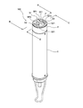
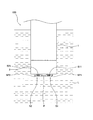
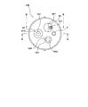
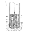
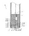
図1は本発明に用いる液体分析計(以下「NH4センサー」という)100の斜視図、図2はNH4センサー100の使用状態を示す図、図3はNH4センサー100の先端面を示す図(但し、センサーS2を取り外した状態)、図4は図3のA−A断面図、図5は図1のB−B断面図(又はC−C断面図)である。これらの図に示すように、NH4センサー100は、3つのセンサーS1、S2、S3が一体となったものであって、センサーS1、S2、S3として、基準電位を測定するための基準電極(比較電極)S3と、アンモニウムイオンによる電位を測定するためのアンモニウムイオン電極S1と、アンモニウムイオンに対するカリウムイオンの干渉を補正するために用いられるカリウムイオンによる電位を測定するためのカリウムイオン電極S2とを備えている。測定対象溶液のカリウムイオン濃度が高い場合には、アンモニウムイオン濃度測定に対するカリウムイオンの干渉の影響が大きくなり、アンモニウムイオン測定の妨げとなる恐れが生じる。 Figure 1 is a perspective view of a liquid analyzer (hereinafter referred to as "NH 4 sensor") 100 for use in the present invention, FIG, 3 2 showing a state of use of NH 4 sensor 100 indicates a distal end surface of the NH 4 Sensor 100 FIG. 4 is a sectional view taken along the line AA in FIG. 3 and FIG. 5 is a sectional view taken along the line BB in FIG. 1 (or a sectional view taken along the line CC). As shown in these drawings, the NH 4 sensor 100 is a combination of three sensors S1, S2, and S3. As the sensors S1, S2, and S3, a reference electrode (for measuring a reference potential) ( Comparative electrode) S3, an ammonium ion electrode S1 for measuring the potential due to ammonium ions, and a potassium ion electrode S2 for measuring the potential due to potassium ions used to correct interference of potassium ions with ammonium ions I have. When the potassium ion concentration of the solution to be measured is high, the influence of the interference of potassium ions on the measurement of the ammonium ion concentration becomes large, which may hinder the ammonium ion measurement.
NH4センサー100は、概略細円筒状の筐体を有し、その基端側(図1では下側)に持ち運び用の鎖が設けてあり、その反対側の先端面に3つのセンサーS1、S2、S3のセンサー面SP1、SP2、SP3が外側へ露出するように設置してある。なお、本実施形態においてセンサー面SP1、SP2、SP3とは、各電極の応答膜S11、S21や液絡部S31が形成されている面のことを指す。 The NH 4 sensor 100 has a substantially thin cylindrical housing, a carrying chain is provided on the base end side (lower side in FIG. 1), and three sensors S1, The sensor surfaces SP1, SP2, and SP3 of S2 and S3 are installed so as to be exposed to the outside. In the present embodiment, the sensor surfaces SP1, SP2, and SP3 indicate surfaces on which the response films S11 and S21 and the liquid junction portion S31 of each electrode are formed.
そして図2に示すようにNH4センサー100の先端面が分析対象液(被処理液)L中において鉛直下向きとなるように浸され、各センサーS1、S2、S3のセンサー面SP1、SP2、SP3が分析対象液L中に浸された状態で各電位の測定を行い、分析対象液L中のアンモニウムイオン濃度を測定する。図1及び図2からも分かるように、3つのセンサーS1、S2、S3のうち2つについては分析中にセンサー面SP1、SP2に気泡が溜まるのを防ぐためにセンサー面SP1、SP2を筐体の軸方向に対して傾斜して設けてある。さらに、傾斜している2つのセンサー面SP1、SP2についてはその向きが同じ所定方向を向くように構成してある。 Then, as shown in FIG. 2, the tip surface of the NH 4 sensor 100 is immersed so as to be vertically downward in the analysis target liquid (liquid to be processed) L, and the sensor surfaces SP1, SP2, SP3 of the sensors S1, S2, S3. Each potential is measured in a state immersed in the analysis target liquid L, and the ammonium ion concentration in the analysis target liquid L is measured. As can be seen from FIGS. 1 and 2, for two of the three sensors S1, S2, and S3, the sensor surfaces SP1 and SP2 are attached to the casing in order to prevent bubbles from being accumulated on the sensor surfaces SP1 and SP2 during analysis. Inclined with respect to the axial direction. Further, the two inclined sensor surfaces SP1 and SP2 are configured such that the directions thereof face the same predetermined direction.
NH4センサー100の先端面は円形状に形成され、その中心線上に基準電極S3のセンサー面SP3と、後述する温度計保護管Pとが並んで配置してある。また、前記中心線に直交する中心線よりもややずれた位置に一列に並んでアンモニウムイオン電極S1の先端部と、カリウムイオン電極S2の先端部とが並んで配置してある。 A tip surface of the NH 4 sensor 100 is formed in a circular shape, and a sensor surface SP3 of the reference electrode S3 and a thermometer protection tube P described later are arranged side by side on the center line thereof. Further, the tip of the ammonium ion electrode S1 and the tip of the potassium ion electrode S2 are arranged in a line at a position slightly shifted from the center line orthogonal to the center line.
図4,図5に示すように、NH4センサー100は、基端側に中空部を有し、先端側に中実部が形成された概略円筒形状をしたボディ1と、前記ボディ1に差し込まれた3つのセンサーS1、S2、S3と、前記ボディ1の先端側を覆うように設けられているキャップ状の押圧機構2とを具備して構成されている。押圧機構2は、前記3つのセンサーS1、S2、S3を前記ボディ1に対して押圧して固定する。 As shown in FIGS. 4 and 5, the NH 4 sensor 100 has a generally cylindrical body 1 having a hollow portion on the proximal end side and a solid portion formed on the distal end side, and is inserted into the body 1. The three sensors S 1, S 2, S 3 and a cap-like pressing mechanism 2 provided so as to cover the front end side of the body 1 are configured. The pressing mechanism 2 presses and fixes the three sensors S1, S2, and S3 against the body 1.
前記ボディ1には軸方向に延びる4つの差し込み穴PH1、PH2、PH3、PH4が形成されており、概略円筒状をなす3つのセンサーS1、S2、S3と前記温度計保護管Pがそれぞれ対応する差し込み穴PH1、PH2、PH3、PH4に差し込んである。また、この差し込み穴PH1、PH2、PH3にはめねじは形成されておらず、各センサーS1、S2、S3が単に差し込まれるだけである。なお、温度計保護管Pについては外れないように差し込み穴PH4に対して固定してある。また、温度計保護管Pの内部には、前記各センサーS1、S2、S3の測定値に対して温度補償をする際に用いられる温度を測定する温度センサーTSが収容してある。 The body 1 is formed with four insertion holes PH1, PH2, PH3, PH4 extending in the axial direction, and the three sensors S1, S2, S3 having a substantially cylindrical shape correspond to the thermometer protective tube P, respectively. Inserted into insertion holes PH1, PH2, PH3, PH4. Further, no female screw is formed in the insertion holes PH1, PH2, and PH3, and the sensors S1, S2, and S3 are simply inserted. The thermometer protection tube P is fixed to the insertion hole PH4 so as not to come off. Further, inside the thermometer protection tube P is housed a temperature sensor TS for measuring a temperature used when temperature compensation is performed on the measured values of the sensors S1, S2, and S3.
3つのセンサーS1、S2、S3について共通している部分について説明すると、各図からも分かるように各センサーS1、S2、S3は概略円筒形状に形成された樹脂製の支持管S12、S22、S32を有し、当該支持管S12、S22、S32の内部には内部液S13、S23、S33と、当該内部液S13、S23、S33に浸漬された内部電極S1E、S2E、S3Eとが収容されている。前記支持管S12、S22、S32の先端には開口部が形成されており、この開口部を塞ぐように応答膜S11、S21又は液絡部S31が設けてある。また、支持管S12、S22、S32の外周面にOリングが設けてあり、前記差し込み穴PH1、PH2、PH3との間で軸シールをなすように構成してある。さらに、各センサーS1、S2、S3の基端は前記差し込み穴PH1、PH2、PH3の最奥において電極端子Dと接触し、取得された各電位がその電極端子Dから外部の演算装置へと伝達されるようにしてある。また、支持管S12、S22、S32の外観形状について共通している部分についてさらに詳述すると、各センサーS1、S2、S3の支持管S12、S22、S32は、先端部が基端部側よりも直径の大きい太円筒部S14、S24、S34を有し、この太円筒部S14、S24、S34の基端側端面が前記差し込み穴PH1、PH2、PH3に形成された段部に係合して前記ボディ1と接触するボディ接触面S17、S27、S37としての機能を果たす。また太円筒部S14、S24、S34の外周面中央部には半径方向に突出したリング状の突出部S15、S25、S35が形成してあり、この突出部S15、S25、S35の先端側平面が前記押圧機構2と係合する係合部S16、S26、S36として構成してある。すなわち、この係合部S16、S26、S36が前記押圧機構2により前記ボディ1側へと押されることにより、前記ボディ接触面S17、S27、S37がボディ1へと押しつけられ、各センサーS1、S2、S3がボディ1に対して所定の力で固定されることになる。 The common portions of the three sensors S1, S2, and S3 will be described. As can be seen from the drawings, each of the sensors S1, S2, and S3 is a resin support tube S12, S22, and S32 formed in a substantially cylindrical shape. The support tubes S12, S22, S32 contain internal liquids S13, S23, S33 and internal electrodes S1E, S2E, S3E immersed in the internal liquids S13, S23, S33. . An opening is formed at the tip of each of the support tubes S12, S22, S32. A response film S11, S21 or a liquid junction S31 is provided so as to close the opening. Further, O-rings are provided on the outer peripheral surfaces of the support tubes S12, S22, and S32, and a shaft seal is formed between the insertion holes PH1, PH2, and PH3. Further, the base ends of the sensors S1, S2, and S3 are in contact with the electrode terminals D at the innermost positions of the insertion holes PH1, PH2, and PH3, and the obtained potentials are transmitted from the electrode terminals D to an external arithmetic unit. It is supposed to be. Further, the portions common to the external shapes of the support tubes S12, S22, and S32 will be described in more detail. It has thick cylindrical portions S14, S24, S34 having a large diameter, and the base end side end surfaces of the thick cylindrical portions S14, S24, S34 engage with stepped portions formed in the insertion holes PH1, PH2, PH3, and It functions as body contact surfaces S17, S27, and S37 that come into contact with the body 1. Further, ring-shaped projecting portions S15, S25, and S35 projecting in the radial direction are formed in the central portions of the outer peripheral surfaces of the thick cylindrical portions S14, S24, and S34, and the front end side planes of the projecting portions S15, S25, and S35 are formed. The engaging portions S16, S26, and S36 that engage with the pressing mechanism 2 are configured. That is, when the engaging portions S16, S26, and S36 are pressed toward the body 1 by the pressing mechanism 2, the body contact surfaces S17, S27, and S37 are pressed against the body 1, and the sensors S1, S2 are pressed. , S3 is fixed to the body 1 with a predetermined force.
3つのセンサーS1、S2、S3の内、前記基準電極S3は、その中心線(延伸軸線)に対して垂直な方向にセンサー面SP3が形成されており、図4に示すように液絡部S31が支持管S32の先端から着脱可能に構成してあり、連続使用による汚れ等により液絡部S31としての機能が低下してきた場合には交換できるようにしてある。 Of the three sensors S1, S2, S3, the reference electrode S3 has a sensor surface SP3 formed in a direction perpendicular to the center line (extension axis) thereof, and as shown in FIG. Is configured to be detachable from the tip of the support tube S32, and can be replaced when the function as the liquid junction S31 is deteriorated due to dirt or the like due to continuous use.
アンモニウムイオン電極S1及びカリウムイオン電極S2は、図5に示すように、応答膜S11、S21が設けられており、そのセンサー面SP1、SP2はセンサーS1、S2の中心軸(延伸軸線)に対して傾斜して設けてある。両センサーS1,S2の形状は略同じ形状をしている。 As shown in FIG. 5, the ammonium ion electrode S1 and the potassium ion electrode S2 are provided with response films S11 and S21, and the sensor surfaces SP1 and SP2 are in relation to the central axes (extension axes) of the sensors S1 and S2. Inclined. Both sensors S1, S2 have substantially the same shape.
押圧機構2は、全てのセンサーS1、S2、S3を一括して前記ボディ1に対して押圧するものである。断面図においては、アンモニア計100の先端面において概略コの字状の部材として示されるものであり、前記ボディ1の先端部を略覆うものである。また、前記ボディ1の先端部を覆った状態において各センサーS1、S2、S3のセンサー面SP1、SP2、SP3と前記温度計保護管Pの先端とを外部へと露出させるための貫通孔TH1、TH2、TH3、TH4を4つ備えている。 The pressing mechanism 2 presses all the sensors S1, S2, S3 against the body 1 at once. In the cross-sectional view, it is shown as a substantially U-shaped member on the front end surface of the ammonia meter 100 and substantially covers the front end portion of the body 1. Further, in a state where the front end portion of the body 1 is covered, the through holes TH1 for exposing the sensor surfaces SP1, SP2, SP3 of the sensors S1, S2, S3 and the front end of the thermometer protective tube P to the outside, Four TH2, TH3, and TH4 are provided.
本実施形態のアンモニウムイオン電極S1の内部液S13には、塩化アンモニウムが含まれており、内部電極S1EとしてはAg/AgCl電極が用いられている。また、応答膜S11は、選択的にアンモニウムイオンに応答する膜であり、半透膜としての性質を有する。このような各イオンに対応する膜としては、具体的には、例えば有機溶媒とそれらを担持するポリ塩化ビニル樹脂やシリコーンゴム等からなるものが挙げられる。一方、基準電極S3の内部液S33としては過飽和の塩化カリウム溶液が用いられ、内部電極S3EとしてはAg/AgCl電極が用いられている。 The internal liquid S13 of the ammonium ion electrode S1 of the present embodiment contains ammonium chloride, and an Ag / AgCl electrode is used as the internal electrode S1E. The response membrane S11 is a membrane that selectively responds to ammonium ions, and has a property as a semipermeable membrane. Specific examples of such a film corresponding to each ion include, for example, a film made of an organic solvent and a polyvinyl chloride resin or silicone rubber supporting them. On the other hand, a supersaturated potassium chloride solution is used as the internal liquid S33 of the reference electrode S3, and an Ag / AgCl electrode is used as the internal electrode S3E.
当該アンモニウムイオン電極S1の応答膜S11の膜電位(mV)は下記式(1)で表すことができる。 The membrane potential (mV) of the response membrane S11 of the ammonium ion electrode S1 can be expressed by the following formula (1).

ここで、式(1)中の各パラメータはそれぞれ以下のとおりである。
E:アンモニウムイオン電極S1の応答膜S11の膜電位(mV)
EOIon:アンモニウムイオン電極S1の標準電極電位(mV)
R:気体定数
F:ファラデー定数
T:絶対温度(K)
aN, Sample:分析対象液L中のNH4 +のイオン活量(moL/L)
aN, Ion:アンモニウムイオン電極S1の内部液S13中のNH4 +のイオン活量(moL/L)
aCl, Ref:基準電極S3の内部液S33中のCl−のイオン活量(moL/L)
aCl, Ion:アンモニウムイオン電極S1の内部液S13中のCl−のイオン活量(moL/L)
Here, each parameter in Formula (1) is as follows, respectively.
E: Membrane potential (mV) of the response membrane S11 of the ammonium ion electrode S1
E O Ion: Standard electrode potential (mV) of the ammonium ion electrode S1
R: Gas constant F: Faraday constant T: Absolute temperature (K)
a N, Sample : NH 4 + ion activity (moL / L) in the liquid L to be analyzed
a N , Ion : NH 4 + ion activity (moL / L) in the internal liquid S13 of the ammonium ion electrode S1
a Cl , Ref : Cl − ion activity (moL / L) in the internal liquid S33 of the reference electrode S3
a Cl , Ion : Cl − ion activity (moL / L) in the internal liquid S13 of the ammonium ion electrode S1
本実施形態においては、式(1)中の実線で囲まれたB項全体が1になる点が測定可能な濃度範囲内に入るように各イオンのイオン活量(イオン濃度)が調整されていることにより、分析対象液L中のアンモニウムイオンの濃度範囲内、すなわち測定レンジ内で、等温交点を得ることができる。更に、本実施形態では、内部液S13の浸透圧が分析対象液Lの浸透圧と同程度になるように、内部液S13中のアンモニウムイオンの濃度と塩化物イオンの濃度とが調整されている。なお、式(1)に基づいてシミュレーションを行い、等温交点が測定レンジ内に入るように内部液を調製してもよい。 In this embodiment, the ion activity (ion concentration) of each ion is adjusted so that the point where the entire B term surrounded by the solid line in formula (1) becomes 1 falls within the measurable concentration range. Thus, an isothermal intersection can be obtained within the concentration range of ammonium ions in the analysis target liquid L, that is, within the measurement range. Furthermore, in this embodiment, the concentration of ammonium ions and the concentration of chloride ions in the internal liquid S13 are adjusted so that the osmotic pressure of the internal liquid S13 is approximately the same as the osmotic pressure of the analysis target liquid L. . In addition, a simulation may be performed based on Formula (1), and an internal liquid may be prepared so that an isothermal intersection may enter into a measurement range.
このように構成した本実施形態のアンモニウム計100によれば、アンモニウムイオン電極S1の内部液S13中のアンモニウムイオンの濃度と塩化物イオンの濃度とを変動させることにより、内部液S13の浸透圧を分析対象液Lの浸透圧と同程度になるように調製しながら、分析対象液L中のアンモニウムイオンの濃度範囲内で等温交点が得られるので、溶解性蒸発残留物および/またはカリウムイオン濃度が高い廃水を対象とした場合でも共存イオンおよび/またはカリウムイオンの影響を受けずにアンモニア濃度を正確に測定できることを本願発明者は見出した。 According to the ammonium meter 100 of the present embodiment configured as described above, the osmotic pressure of the internal liquid S13 is changed by changing the concentration of ammonium ions and the concentration of chloride ions in the internal liquid S13 of the ammonium ion electrode S1. Since the isothermal intersection is obtained within the concentration range of ammonium ions in the analysis target liquid L while adjusting to the same osmotic pressure as the analysis target liquid L, the concentration of soluble evaporation residue and / or potassium ion is reduced. The present inventor has found that the ammonia concentration can be accurately measured without being affected by coexisting ions and / or potassium ions even when high wastewater is targeted.
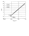
上記NH4センサー100においては、以下のような試験が行われている。即ち、基準電極(比較電極)S3として、内部液S33が3.33Mの塩化カリウム溶液であるものが使用された。一方、アンモニウムイオン電極S1の内部液S13は、等温交点が0.0000714M(1ppm・N)で、浸透圧が塩濃度0.03Mの水溶液と同一になるように調製された。上記の構成を有する基準電極S3とアンモニウムイオン電極S1とを用いて、温度を変化させながら電極の応答が計算式(1)に従っているかどうかが確認された。その結果は、図19に示すように、アンモニウムイオン濃度0.0000714M(1ppm・N)に等温交点を持つことが確認されている。なお、等温交点が測定可能な濃度範囲からずれると、測定可能な濃度範囲内の測定値Eが式(1)に完全に従わない場合には、式(1)から予想されるEと、実際の測定値Eとの間にずれが大きくなるので測定誤差が大きくなる。 The NH 4 sensor 100 is subjected to the following tests. That is, as the reference electrode (comparative electrode) S3, an internal liquid S33 was used which was a 3.33M potassium chloride solution. On the other hand, the internal solution S13 of the ammonium ion electrode S1 was prepared such that the isothermal intersection was 0.0000714M (1 ppm · N) and the osmotic pressure was the same as that of the aqueous solution having a salt concentration of 0.03M. Using the reference electrode S3 and the ammonium ion electrode S1 having the above-described configuration, it was confirmed whether or not the response of the electrode complies with the calculation formula (1) while changing the temperature. As a result, as shown in FIG. 19, it was confirmed that the ammonium ion concentration is 0.0000714M (1 ppm · N) and has an isothermal intersection. If the isothermal intersection deviates from the measurable concentration range, if the measured value E within the measurable concentration range does not completely follow equation (1), E is expected from equation (1) and actually Since the difference between the measured value E and the measured value E increases, the measurement error increases.
即ち、NH4センサー100において、測定対象のアンモニウムイオンの測定可能な濃度範囲は、基準電極(比較電極)S3の内部液S33中の塩化物イオン濃度よりも低いことが好ましい。また、アンモニウムイオン電極S1の内部液S13は、アンモニウムイオンと塩化物イオンとを含有しており、アンモニウムイオン電極S1の内部液S13は、アンモニウムイオン電極S1の内部液S13の浸透圧と等温交点とが所望の値になり、かつ、当該等温交点が前記測定可能な濃度範囲内に含まれているように、前記アンモニウムイオン電極S1の内部液S13中のアンモニウムイオンの濃度と塩素イオンの濃度が調整されたものであり、当該塩素イオンの濃度が、前記基準電極S3の内部液S33中の塩素イオンの濃度とは異なっていることが好ましい。 That is, in the NH 4 sensor 100, the measurable concentration range of ammonium ions to be measured is preferably lower than the chloride ion concentration in the internal liquid S33 of the reference electrode (comparative electrode) S3. The internal liquid S13 of the ammonium ion electrode S1 contains ammonium ions and chloride ions, and the internal liquid S13 of the ammonium ion electrode S1 has an osmotic pressure and an isothermal intersection with the internal liquid S13 of the ammonium ion electrode S1. The concentration of ammonium ions and the concentration of chloride ions in the internal solution S13 of the ammonium ion electrode S1 are adjusted so that the isotherm intersection is included in the measurable concentration range. It is preferable that the concentration of the chlorine ions is different from the concentration of the chlorine ions in the internal liquid S33 of the reference electrode S3.
ところで従来、生物学的窒素除去の処理方式としては、浮遊生物を利用した活性汚泥法、浮遊生物と流動型生物膜を利用した担体利用処理法、生物膜を利用した接触酸化法が用いられる。本願発明の溶解性蒸発残留物および/またはカリウムイオン濃度が高い廃水を対象とした前述のNH4センサー100を使用する硝化槽の空気量制御方法はどの処理方式にも適用可能である。 Conventionally, as a treatment system for biological nitrogen removal, an activated sludge method using suspended organisms, a carrier utilizing treatment method using suspended organisms and fluidized biological membranes, and a catalytic oxidation method utilizing biological membranes are used. The method for controlling the amount of air in the nitrification tank using the NH 4 sensor 100 described above for waste water having a soluble evaporation residue and / or high potassium ion concentration according to the present invention can be applied to any treatment method.
前述のように、測定対象溶液のカリウムイオン濃度が高い場合には、アンモニウムイオン濃度測定に対するカリウムイオンの干渉の影響が大きく、アンモニウムイオン測定の妨げとなるため、カリウムイオン濃度が高いし尿処理では、NH4センサー100でのアンモニア濃度測定がより困難になると思われる。そのため、し尿処理に関し、詳細な説明を行う。 As described above, when the potassium ion concentration of the solution to be measured is high, the influence of potassium ion interference on the ammonium ion concentration measurement is large and hinders the ammonium ion measurement. It seems that ammonia concentration measurement with the NH 4 sensor 100 becomes more difficult. Therefore, a detailed description will be given regarding human waste processing.
し尿等の主な性状は一例として、pH:7〜8、SS:5,000mg/L〜15,000mg/L、BOD:2,000〜15,000mg/L、アンモニア性窒素:500〜5,000mg/Lである。 The main properties such as human waste are, for example, pH: 7 to 8, SS: 5,000 mg / L to 15,000 mg / L, BOD: 2,000 to 15,000 mg / L, ammoniacal nitrogen: 500 to 5,000 mg / L.
し尿処理の生物学的脱窒素処理方式としては、活性汚泥法である循環式硝化脱窒素法を適用し、標準脱窒素処理方式、高負荷脱窒素処理方式、膜分離高負荷脱窒素処理方式、浄化槽汚泥の混入比率の高い脱窒素処理方式、前脱水+標準脱窒素処理方式などが適用されている。 As biological denitrification treatment method for human waste treatment, we apply circulation nitrification denitrification method which is activated sludge method, standard denitrification treatment method, high load denitrification treatment method, membrane separation high load denitrogenation treatment method, Denitrification treatment method with high mixing ratio of septic tank sludge, pre-dehydration + standard denitrification treatment method, etc. are applied.
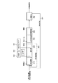
〔標準脱窒素処理方式〕
図6は標準脱窒素処理方式による処理フローの一例を示す図である。同図に示すように、この標準脱窒素処理方式による処理フローは、脱窒素槽210と、硝化槽220と、二次脱窒素槽230と、再曝気槽240と、沈殿池250とを設置して、この順番に処理を行う構成となっている。
[Standard denitrification method]
FIG. 6 is a diagram showing an example of a processing flow according to the standard denitrification method. As shown in the figure, the processing flow by this standard denitrification treatment system is provided with a denitrification tank 210, a nitrification tank 220, a secondary denitrification tank 230, a re-aeration tank 240, and a sedimentation basin 250. Thus, the processing is performed in this order.
即ち、スクリーン等でし渣等を除去した前処理後のし尿及び浄化槽汚泥(以下「し尿等」ともいう)を希釈水とともに脱窒素槽210に供給する。脱窒素槽210に流入するし尿等の量の1〜10倍の希釈水を供給する。希釈水としては井戸水等が用いられるが、この他に雑排水(脱水ろ液、機器洗浄水など場内で発生する排水)も希釈水と一緒に供給される。以下、雑排水を含めて希釈水と呼ぶこととする。脱窒素槽210には沈殿池250から返送される返送汚泥及び硝化槽220の末端から循環される硝化液(硝化循環液)も流入する。脱窒素槽210は無酸素状態下で撹拌され、脱窒素菌がし尿および浄化槽汚泥中のBOD成分を利用しながら循環された硝化液中の硝酸性窒素および亜硝酸性窒素(以下、NOX-N)を窒素ガスに転換する脱窒素処理を行う。 That is, the pre-treated human waste and septic tank sludge (hereinafter also referred to as “human waste etc.”) from which screen residue and the like have been removed are supplied to the denitrification tank 210 together with the diluted water. Diluted water 1 to 10 times as much as the amount of manure flowing into the denitrification tank 210 is supplied. Well water or the like is used as dilution water, but miscellaneous wastewater (drainage generated in the field such as dehydrated filtrate and equipment washing water) is also supplied together with the dilution water. Hereinafter, it will be called dilution water including miscellaneous wastewater. Returned sludge returned from the sedimentation tank 250 and a nitrification liquid (nitrification circulation liquid) circulated from the end of the nitrification tank 220 also flow into the denitrification tank 210. The denitrification tank 210 is stirred under anaerobic condition, and nitrate nitrogen and nitrite nitrogen (hereinafter referred to as NO X −) in the nitrification liquid circulated while utilizing the BOD component in the denitrification bacteria and septic tank sludge. Perform denitrification to convert N) into nitrogen gas.
次に、脱窒素槽210から流出した混合液は硝化槽220に導入され、曝気される。ここでは、脱窒素槽210で除去しきれなかったBODが除去されるとともに、硝化菌の作用によりアンモニア性窒素(以下、「NH4-N」という)がNOX-Nに酸化される。なお、硝化槽220には、DO計223と、pH計225と、前記NH4センサー100が設置され、また下記する曝気装置によって空気が供給される。 Next, the liquid mixture flowing out from the denitrification tank 210 is introduced into the nitrification tank 220 and aerated. Here, BOD that could not be removed in the denitrification tank 210 is removed, and ammonia nitrogen (hereinafter referred to as “NH 4 —N”) is oxidized to NO X —N by the action of nitrifying bacteria. The nitrification tank 220 is provided with a DO meter 223, a pH meter 225, and the NH 4 sensor 100, and air is supplied by an aeration apparatus described below.
硝化槽220で硝化が進行した混合液の大部分は、硝化液循環配管221によって、前記脱窒素槽210に循環され、残りは二次脱窒素槽230に流入する。脱窒素槽210と同様に無酸素状態である二次脱窒素槽230では、硝化槽220から流入したNOX-Nが脱窒素される。ここでの脱窒素では内生呼吸型脱窒素も行われるが、メタノール等の水素供与体を添加することで、脱窒素反応の効率化を図ることが好適である。 Most of the mixed liquid that has undergone nitrification in the nitrification tank 220 is circulated to the denitrification tank 210 by the nitrification liquid circulation pipe 221, and the rest flows into the secondary denitrification tank 230. In the secondary denitrification tank 230 which is in an oxygen-free state like the denitrification tank 210, NO X -N flowing from the nitrification tank 220 is denitrified. In this denitrification, endogenous respiration type denitrification is also performed, but it is preferable to increase the efficiency of the denitrification reaction by adding a hydrogen donor such as methanol.
次に、二次脱窒素槽230で残留したメタノール等の有機物は、再曝気槽240で曝気処理することで除去される。 Next, organic matters such as methanol remaining in the secondary denitrification tank 230 are removed by aeration in the re-aeration tank 240.
次に、再曝気槽240からの流出水は沈澱池250に導かれ、ここで汚泥と処理水に分離される。沈殿池250で濃縮された汚泥の一部は、汚泥返送管251によって、返送汚泥として脱窒素槽210に送られ、残りは余剰汚泥として汚泥処理される。沈殿池250から越流した処理水は、凝集沈殿処理等の高度処理を経た後、放流される。 Next, the effluent water from the re-aeration tank 240 is guided to the sedimentation basin 250 where it is separated into sludge and treated water. Part of the sludge concentrated in the sedimentation basin 250 is sent to the denitrification tank 210 as return sludge through the sludge return pipe 251 and the rest is sludge treated as excess sludge. The treated water overflowed from the settling basin 250 is discharged after undergoing advanced treatment such as coagulation sedimentation treatment.
標準脱窒素処理方式のMLSS(Mixed Liquor Suspended Solids)は、6000mg/L程度で運転されることが多い。 MLSS (Mixed Liquor Suspended Solids) with standard denitrification treatment is often operated at about 6000 mg / L.
生物学的硝化脱窒素法での各反応槽の液温は、投入するし尿等や希釈水よりも高くなる。これは、硝化反応および脱窒素反応は発熱反応であり、各反応槽での生物反応により生じる発生熱、および、曝気装置で発生する吹き込み空気の熱量などの反応槽への流入熱が、曝気による排気ガスの持ち出す熱量などの反応槽からの流出熱よりも大きくなるためである。亜硝酸菌の活性は38℃まで高くなるが、38℃を超えると低下するため、硝化槽220の処理の安定化のため、生物学的硝化脱窒処理の液温の上限は38℃とするのが好適である。 In the biological nitrification denitrification method, the temperature of each reaction tank is higher than that of the urine and dilution water to be added. This is because the nitrification reaction and the denitrification reaction are exothermic reactions, and the heat generated by the biological reaction in each reaction tank and the inflow heat to the reaction tank such as the amount of blown air generated in the aeration apparatus are caused by aeration. This is because the amount of heat that the exhaust gas takes out becomes larger than the heat that flows out of the reaction tank. The activity of nitrous acid bacteria increases to 38 ° C, but decreases when the temperature exceeds 38 ° C. Therefore, the upper limit of the liquid temperature of biological nitrification denitrification treatment is 38 ° C in order to stabilize the treatment of the nitrification tank 220. Is preferred.
〔高負荷脱窒素処理方式、膜分離高負荷脱窒素処理方式〕
高負荷脱窒素処理方式や膜分離高負荷脱窒素処理方式の高負荷処理方式では、前処理したし尿等を無希釈のまま高容積負荷の硝化脱窒素設備で処理し、固液分離後の分離水を凝集沈殿処理等の高度処理を経た後、放流する方式である。高負荷処理方式では、高容積負荷運転を可能とするため、MLSSを8,000〜20,000mg/Lに維持する必要がある。この高MLSSの活性汚泥の固液分離方式としては、高負荷脱窒素処理方式では、遠心濃縮機等の機械分離方式の採用が一般的であり、膜分離高負荷脱窒素処理方式では、精密ろ過膜(MF膜)や限外ろ過膜(UF膜)による膜分離方式が採用される。
[High load denitrification method, membrane separation high load denitrification method]
In the high load treatment method such as high load denitrification method or membrane separation high load denitrogenation method, pre-treated human waste is treated with nitrification denitrification equipment with high volume load without dilution and separation after solid-liquid separation. In this method, water is discharged after advanced treatment such as coagulation sedimentation treatment. In the high load treatment method, MLSS needs to be maintained at 8,000 to 20,000 mg / L in order to enable high volume load operation. As the high-MLSS activated sludge solid-liquid separation method, a mechanical separation method such as a centrifugal concentrator is generally used in the high-load denitrification method, and in the high-load denitrification method of membrane separation, microfiltration is used. A membrane separation method using a membrane (MF membrane) or ultrafiltration membrane (UF membrane) is adopted.
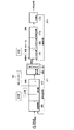
図7は膜分離高負荷脱窒素処理方式による処理フローの一例を示す図である。同図に示すように、この膜分離高負荷脱窒素処理方式による処理フローは、脱窒素槽260と、硝化槽270と、膜分離原水槽280と、二次硝化槽290と、二次脱窒素槽300と、再曝気槽310と、沈殿池320とを設置して、この順番に処理を行う構成となっている。処理の基本原理は前記標準脱窒素処理方式に準じている。 FIG. 7 is a diagram showing an example of a processing flow by a membrane separation high-load denitrification method. As shown in the figure, the treatment flow by this membrane separation high-load denitrification method includes a denitrification tank 260, a nitrification tank 270, a membrane separation raw water tank 280, a secondary nitrification tank 290, and a secondary denitrification tank. A tank 300, a re-aeration tank 310, and a sedimentation basin 320 are installed, and processing is performed in this order. The basic principle of the treatment is in accordance with the standard denitrification method.
即ち、前処理したし尿等を脱窒素槽260に流入させる。脱窒素槽260ではし尿等のBODを利用して、嫌気的条件下で硝化槽270からの循環液中のNOX-Nを脱窒素する。脱窒素槽260の流出液は硝化槽270に流入し、好気的条件下でNH4-NがNOX-Nに硝化される。NOX-Nを含む混合液は、硝化液循環配管271によって、脱窒素槽260へ循環される。この処理フローでは、膜分離原水槽280から脱窒素槽260へ循環するフローとなっているが、硝化槽270から脱窒素槽260に循環する方式としてもよい。 That is, pretreated human urine or the like is caused to flow into the denitrification tank 260. In the denitrification tank 260, NO x -N in the circulating liquid from the nitrification tank 270 is denitrogenated under anaerobic conditions using BOD such as human waste. The effluent from the denitrification tank 260 flows into the nitrification tank 270, and NH 4 -N is nitrified to NO x -N under aerobic conditions. The mixed solution containing NO X -N is circulated to the denitrification tank 260 through the nitrification solution circulation pipe 271. In this processing flow, the flow is circulated from the membrane separation raw water tank 280 to the denitrification tank 260, but it may be circulated from the nitrification tank 270 to the denitrification tank 260.
硝化槽270からの流出液は膜分離原水槽280を経て膜分離装置281で固液分離される。膜分離装置281で分離された透過水は後段の二次硝化槽290に流入し、膜で濃縮された汚泥の一部は返送汚泥として脱窒素槽260に戻され、残りは余剰汚泥として汚泥処理される。脱窒素槽260および硝化槽270のMLSSは8,000〜12,000mg/Lで運転されることが多い。高負荷脱窒素処理方式では、反応液温よりも水温の低い希釈水を用いないため、反応槽液温を38℃以下に保つために冷却装置を備えている。 The effluent from the nitrification tank 270 is solid-liquid separated by the membrane separation device 281 through the membrane separation raw water tank 280. The permeated water separated by the membrane separation device 281 flows into the subsequent secondary nitrification tank 290, a part of the sludge concentrated by the membrane is returned to the denitrification tank 260 as return sludge, and the rest is sludge treated as excess sludge. Is done. The MLSS of the denitrification tank 260 and the nitrification tank 270 is often operated at 8,000 to 12,000 mg / L. In the high-load denitrogenation method, dilution water having a lower water temperature than the reaction solution temperature is not used, and therefore a cooling device is provided to keep the reaction vessel solution temperature at 38 ° C. or lower.
膜分離装置281で分離された透過水は、雑排水とともに二次硝化槽290へ流入する。二次硝化槽290では好気的条件下でNH4-NがNOX-Nに硝化される。二次脱窒素槽300、再曝気槽310、沈殿池320、汚泥返送管321の機能は、上記標準脱窒素処理方式と同様である。二次硝化槽290、二次脱窒素槽300、再曝気槽310のMLSSは、4,000〜6,000mg/Lで運転される。 The permeated water separated by the membrane separation device 281 flows into the secondary nitrification tank 290 together with miscellaneous waste water. In the secondary nitrification tank 290, NH 4 -N is nitrified to NO x -N under aerobic conditions. The functions of the secondary denitrification tank 300, the re-aeration tank 310, the sedimentation basin 320, and the sludge return pipe 321 are the same as those in the standard denitrification method. MLSS of the secondary nitrification tank 290, the secondary denitrification tank 300, and the re-aeration tank 310 is operated at 4,000 to 6,000 mg / L.
〔浄化槽汚泥の混入比率の高い脱窒素処理方式、前脱水+標準脱窒素処理方式〕
浄化槽汚泥の混入比率の高い脱窒素処理方式や前脱水+標準脱窒素処理方式では、生物学的硝化脱窒素処理の前に前処理後のし尿等の濃縮や脱水の固液分離処理を行い、固形物の除去を行う。これにより、生物処理への流入水の性状が安定し、生物学的硝化脱窒処理の負荷が軽減できる。また、余剰汚泥を前処理後のし尿等とともに脱水する方式の場合、汚泥脱水設備を一元化できる。
[Denitrification treatment method with high mixing ratio of septic tank sludge, pre-dehydration + standard denitrification treatment method]
In the denitrification method with high mixing ratio of septic tank sludge and the pre-dehydration + standard denitrogenation method, concentration of dehydrated human waste after pretreatment and solid-liquid separation treatment of dehydration are performed before biological nitrification denitrification treatment. Remove solids. Thereby, the property of the inflow water to biological treatment is stabilized, and the load of biological nitrification denitrification treatment can be reduced. Moreover, in the case of a system in which excess sludge is dehydrated together with human waste after pretreatment, sludge dewatering equipment can be unified.
図8は前脱水+標準脱窒素処理方式による処理フローの一例を示す図である。同図に示すように、この前脱水+標準脱窒素処理方式による処理フローは、脱水機330と、脱窒素槽340と、硝化槽350と、二次脱窒素槽360と、再曝気槽370と、沈殿池380とを設置して、この順番に処理を行う構成となっている。処理の基本原理は前記標準脱窒素処理方式に準じている。 FIG. 8 is a diagram showing an example of a processing flow by the pre-dehydration + standard denitrification method. As shown in the figure, the processing flow by this pre-dehydration + standard denitrification treatment method is as follows: dehydrator 330, denitrification tank 340, nitrification tank 350, secondary denitrification tank 360, and re-aeration tank 370. In addition, a sedimentation basin 380 is installed and processing is performed in this order. The basic principle of the treatment is in accordance with the standard denitrification method.
この処理フローの場合、前処理後のし尿等を脱水機330で脱水(以下、前脱水)し、脱水後の分離液を脱窒素槽340に流入させる。脱水時の汚泥の調質には無機凝集剤と高分子凝集剤を併用させることが好ましい。 In the case of this processing flow, human waste after pretreatment is dehydrated by the dehydrator 330 (hereinafter, predehydration), and the dehydrated separation liquid is allowed to flow into the denitrification tank 340. It is preferable to use an inorganic flocculant and a polymer flocculant in combination for sludge refining during dehydration.
前脱水処理では生物学的硝化脱窒処理での負荷量が軽減するため、井戸水等の希釈水を使用せずに、機器洗浄水など場内で発生する排水を雑排水として供給する場合が多い。脱窒素槽340以降の機能は、図6に示す前記標準脱窒素処理方式での処理フローと同様なので、その説明は省略する。 In the pre-dehydration treatment, the load in the biological nitrification / denitrification treatment is reduced, so that wastewater generated in the field such as equipment washing water is often supplied as miscellaneous wastewater without using dilution water such as well water. Since the function after the denitrification tank 340 is the same as the process flow in the standard denitrification process shown in FIG. 6, the description thereof is omitted.
前記硝化槽や再曝気槽で用いる曝気装置としては、散気式曝気装置やポンプ循環式曝気装置、空気注入式曝気装置などがある。曝気装置は、し尿等中のBOD除去及び窒素化合物の硝化を生物学的に行うための酸素を槽内液に溶解する装置で、硝化槽で必要とする酸素をできるだけ均一に十分供給でき、また、汚泥、砂等が沈殿することなく、槽内汚泥濃度が実用上十分な均一性を保つような攪拌能力を有するものとする。硝化槽では、し尿等中のBOD除去以外にアンモニア性窒素の硝化を行うため、一般の活性汚泥法の曝気槽に比べ同一のし尿処理量に対して格段に多量の酸素を必要とする。また、総窒素−MLSS負荷や好気性汚泥日令を必要な範囲に保つためには、MLSS濃度を高く維持することが求められる。従って、曝気装置は、高いMLSS濃度の槽内液に対して必要な酸素の供給が十分に可能なものでなくてはならず、また、上述のように多量の酸素を必要とするので、省エネルギーの観点からも酸素溶解効率のよいものが要求される。 Examples of the aeration apparatus used in the nitrification tank and the re-aeration tank include an aeration type aeration apparatus, a pump circulation type aeration apparatus, and an air injection type aeration apparatus. The aeration device is a device that dissolves oxygen for biological removal of BOD in human waste etc. and nitrification of nitrogen compounds in the liquid in the tank, and it can supply the oxygen required in the nitrification tank as uniformly as possible. It is assumed that the tank has a stirring ability such that the sludge concentration in the tank maintains a practically sufficient uniformity without sedimentation of sludge, sand and the like. In the nitrification tank, ammonia nitrogen is nitrified in addition to the removal of BOD in human waste and the like, and therefore, a much larger amount of oxygen is required for the same amount of manure treatment than an aeration tank of a general activated sludge method. In order to keep the total nitrogen-MLSS load and the aerobic sludge age within the necessary ranges, it is required to maintain the MLSS concentration high. Therefore, the aeration apparatus must be capable of sufficiently supplying the necessary oxygen to the liquid in the tank having a high MLSS concentration, and also requires a large amount of oxygen as described above. From this point of view, a material having high oxygen dissolution efficiency is required.
散気式曝気装置は、ブロワから送気管を経て送られた空気を、散気装置で槽内液中に放出し、槽内を攪拌すると同時に酸素溶解を行う。散気装置は、ブロワから送られてくる空気を細かい気泡にして硝化槽に吹き込み、水面に向かって上昇する気泡のエアーリフト効果により槽内に旋回流を形成して槽内液の攪拌混合を行い、且つ液と気泡の接触によって酸素を溶解させる。空気注入式曝気装置も、ブロワにより曝気槽への空気の供給を行う。ポンプ循環方式ではポンプ循環流路でエジェクタ等により空気を吸引することで曝気槽への空気の供給を行う。空気量の制御は配管中のバルブ開度の調整やブロワやポンプのインバータによる出力制御により行うが、インバータによる出力制御での電力削減効果が大きい。 The aeration-type aeration apparatus discharges air sent from a blower through an air supply pipe into the liquid in the tank by the aeration apparatus, and stirs the inside of the tank and simultaneously dissolves oxygen. The air diffuser blows air sent from the blower into fine bubbles, blows it into the nitrification tank, forms a swirling flow in the tank by the air lift effect of the bubbles rising toward the water surface, and stirs and mixes the liquid in the tank. And oxygen is dissolved by contact between the liquid and bubbles. The air injection type aeration apparatus also supplies air to the aeration tank by a blower. In the pump circulation system, air is supplied to the aeration tank by sucking air with an ejector or the like in the pump circulation passage. The air amount is controlled by adjusting the valve opening in the pipe or by controlling the output of the blower or pump inverter. The power control effect of the output control by the inverter is great.
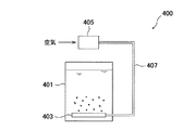
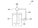
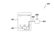
図9は散気式曝気装置400の一例を示す概略構成図、図10はポンプ循環式曝気装置430の一例を示す概略構成図、図11は空気注入式曝気装置460の一例を示す概略構成図である。図9に示す散気式曝気装置400は、ブロワ405から送気管407を経て槽(硝化槽等)401内に送られた空気を、散気装置403で槽内液中に放出する構成となっている。図10に示すポンプ循環式曝気装置430は、槽(硝化槽等)431内の液体を循環ポンプ配管435に取り出して循環ポンプ433によって循環すると共に、循環ポンプ433の下流側の循環ポンプ配管435に設置したエジェクタ437によって循環する液体内に空気を取り込み、この空気の気泡を槽431内に供給する構成となっている。図11に示す空気注入式曝気装置460は、ブロワ463から送気管465を経て槽(硝化槽等)461内に送られた空気を、回転空気分離機467で回転する気泡として槽内液中に放出する構成となっている。空気注入式曝気装置には、この回転空気分散式の他に、ドラフトチューブ式や加圧曝気式や、ディープシャフト式等もある。 FIG. 9 is a schematic configuration diagram illustrating an example of an aeration type aeration apparatus 400, FIG. 10 is a schematic configuration diagram illustrating an example of a pump circulation type aeration apparatus 430, and FIG. 11 is a schematic configuration diagram illustrating an example of an air injection type aeration apparatus 460. It is. The aeration type aeration apparatus 400 shown in FIG. 9 is configured such that the air sent from the blower 405 through the air supply pipe 407 into the tank (nitrification tank or the like) 401 is discharged into the liquid in the tank by the aeration apparatus 403. ing. The pump circulation type aeration apparatus 430 shown in FIG. 10 takes out the liquid in the tank (nitrification tank or the like) 431 to the circulation pump pipe 435 and circulates it with the circulation pump 433, and at the circulation pump pipe 435 on the downstream side of the circulation pump 433. Air is taken into the liquid circulated by the installed ejector 437 and air bubbles are supplied into the tank 431. The air injection type aeration apparatus 460 shown in FIG. 11 passes the air sent from the blower 463 through the air supply pipe 465 into the tank (nitrification tank or the like) 461 into the liquid in the tank as bubbles rotated by the rotary air separator 467. It becomes the composition to discharge. In addition to the rotating air dispersion type, the air injection type aeration apparatus includes a draft tube type, a pressurized aeration type, a deep shaft type, and the like.
上記したNH4センサー100は、硝化槽のNH4-N濃度を把握する目的で設置され、その設置箇所は、硝化槽内のNH4-N濃度を把握できる位置が好ましく、硝化槽内(末端部が好適)、又は硝化液循環配管中、又は硝化液循環配管を分岐した位置に設置した図示しない水質計測器設置槽内、又は前記ポンプ循環式曝気装置430の循環ポンプ配管435中、又は循環ポンプ配管435を分岐した図示しない水質計測器設置水槽内、又は別途設けた図示しない水質計測用配管内、又はこの水質計測配管を分岐した図示しない水質計測器設置槽内がよい(このいずれかにNH4センサーを設置した状態を「硝化槽のNH4センサー」とも称す)。 NH 4 sensor 100 described above is installed for the purpose of grasping the NH 4 -N concentration of the nitrification tank, its installation location is preferably NH 4 -N concentration can grasp the position of the nitrification tank, nitrification tank (terminal Is preferable), or in the nitrification liquid circulation pipe, or in a water quality measuring instrument installation tank (not shown) installed at a position where the nitrification liquid circulation pipe is branched, or in the circulation pump pipe 435 of the pump circulation type aeration apparatus 430, or in the circulation A water quality measuring instrument installation tank (not shown) branched from the pump pipe 435, a water quality measurement pipe (not shown) provided separately, or a water quality measuring instrument installation tank (not shown) branched from the water quality measurement pipe (preferably one of them) The state where the NH 4 sensor is installed is also referred to as the “NH 4 sensor in the nitrification tank”).
NH4センサー以外のpH計やDO計も、上記NH4センサーと同じ位置に設置できる。ちなみに、DO計は隔膜ポーラロ式DO計や光学式DO計が用いられ、本願発明の対象となる溶解性蒸発残留物および/またはカリウムイオン濃度が高い廃水に対しても良好なDO測定が可能である。 NH 4 pH meter or DO meter other than the sensor can also be placed in the same position as the NH 4 sensors. By the way, as the DO meter, a diaphragm polar DO meter and an optical DO meter are used, and it is possible to perform a good DO measurement even on the soluble evaporation residue and / or wastewater with a high potassium ion concentration, which is the object of the present invention. is there.
上記図7に示す高負荷脱窒素処理方式では、二次硝化槽290にもNH4センサーを設置することができる。しかし、二次硝化槽290に比べ硝化槽270での空気量が圧倒的に多いため、NH4センサー設置による空気量削減効果は、硝化槽270に設置したNH4センサーの寄与が圧倒的に大きい。 In the high-load denitrogenation method shown in FIG. 7, an NH 4 sensor can be installed also in the secondary nitrification tank 290. However, since the amount of air in the nitrification tank 270 is overwhelmingly larger than that of the secondary nitrification tank 290, the NH 4 sensor installed in the nitrification tank 270 contributes greatly to the effect of reducing the air amount by installing the NH 4 sensor. .
本発明に係る廃水処理方法は、硝化槽のNH4センサーによるNH4-N測定値に応じて空気量を制御する方法である。具体的には、所定の値に設定した硝化槽NH4-N設定値よりもNH4センサーによる測定値が大きい場合には、前記曝気装置によるブロワ等のインバータ出力制御等により、硝化槽に供給する空気量を増やし、一方、硝化槽NH4-N所定値よりもNH4センサーによる測定値が小さい場合には、前記曝気装置によるブロワ等のインバータ出力制御等により、硝化槽に供給する空気量を減らす制御を行う。これによって、硝化槽内の被処理液のNH4-N濃度が、硝化槽のNH4-N設定濃度となるようにする。 The wastewater treatment method according to the present invention is a method for controlling the amount of air in accordance with the NH 4 —N measured value by the NH 4 sensor of the nitrification tank. Specifically, when the measured value by NH 4 sensor is larger than the set value of nitrification tank NH 4 -N set to a predetermined value, it is supplied to the nitrification tank by inverter output control such as blower by the aeration device. On the other hand, if the measured value by NH 4 sensor is smaller than nitrification tank NH 4 -N predetermined value, the amount of air supplied to the nitrification tank by inverter output control such as blower by the aeration device Control to reduce. Thus, the NH 4 —N concentration of the liquid to be treated in the nitrification tank is set to the NH 4 —N set concentration of the nitrification tank.
また、硝化槽に供給する空気量に応じて、硝化槽のDO値も変化し、硝化槽に供給する空気量を増やす場合には硝化槽のDO値は高くなる傾向にあり、硝化槽に供給する空気量を減らす場合には硝化槽のDO値は低くなる傾向にある。 The DO value of the nitrification tank also changes according to the amount of air supplied to the nitrification tank. When the amount of air supplied to the nitrification tank is increased, the DO value of the nitrification tank tends to increase, and the supply to the nitrification tank When the amount of air to be reduced is reduced, the DO value of the nitrification tank tends to be low.
NH4センサーでの硝化槽NH4-N測定時には、硝化槽NH4-N設定値の他に、硝化槽NH4-N設定値よりも高い値である硝化槽NH4-N警報値を設定するのが好ましい。何故なら、硝化槽のNH4-Nの測定値が硝化槽NH4-N設定値を超えて硝化槽に供給する空気量が高まり、硝化槽に十分量の空気が供給されているにもかかわらず、硝化槽のNH4-Nが次第に高くなり、硝化槽NH4-N警報値に達する場合は、生物反応槽に流入するし尿等の窒素濃度が高い、あるいは生物反応槽に流入するし尿等の流量が多いため、生物反応槽の窒素負荷が高くなっていると考えられる。この様な場合は、反応槽に流入するし尿等の流入量を下げることで、生物反応槽の窒素負荷を低減し、適正な窒素負荷とすることで硝化槽NH4-Nは硝化槽NH4-N警報値を下回ることができ、安定した生物学的硝化脱窒処理の継続が可能となるからである。これに対して、従来のDO制御で同様の運転を行う場合には、反応槽に流入する窒素負荷が高くなると、硝化槽内のDOが所定値以下に下がるので、硝化槽の空気量を増やし硝化槽のDOを回復させる。しかし、反応槽への流入窒素負荷が硝化菌の能力を上回る場合には、硝化槽に流入するNH4-NをNOX-Nに硝化しきれずにNH4-Nが残留しているにもかかわらず、硝化に必要な空気量は供給されているため、硝化槽のDOは2mg/L以上に保たれる状況が生じることもある。そのため、DO制御では、反応槽への流入窒素負荷への対応が難しく、処理水水質の悪化を招くこともある。この様な観点からも、本発明のように、硝化槽のNH4-NをNH4センサーで監視し、反応槽に流入する窒素負荷を適宜調整することで、生物学的硝化脱窒処理の安定化を図ることは、運転管理上好ましい。 NH 4 During the nitrification reactor NH 4 -N measurement at the sensor, in addition to the nitrification tank NH 4 -N setpoint, set the nitrification tank NH 4 -N alarm value is higher than the nitrification tank NH 4 -N setpoint It is preferable to do this. This is because the measured amount of NH 4 -N in the nitrification tank exceeds the set value of the nitrification tank NH 4 -N and the amount of air supplied to the nitrification tank increases, so that a sufficient amount of air is supplied to the nitrification tank. If NH 4 -N in the nitrification tank gradually increases and reaches the alarm value for the nitrification tank NH 4 -N, the concentration of nitrogen in the biological reaction tank and urine is high, or the urine etc. flows into the biological reaction tank. It is considered that the nitrogen load in the biological reaction tank is high because of the large flow rate of the gas. In such a case, by reducing the inflow of human waste such as flowing into the reaction vessel to reduce the nitrogen load of the biological reactor, nitrification tank NH 4 -N by a proper nitrogen load nitrification tank NH 4 This is because the -N alarm value can be exceeded, and stable biological nitrification and denitrification treatment can be continued. On the other hand, when the same operation is performed with the conventional DO control, if the nitrogen load flowing into the reaction tank becomes high, the DO in the nitrification tank falls below a predetermined value, so the amount of air in the nitrification tank is increased. Restore DO in the nitrification tank. However, if the inflow nitrogen load into the reaction tank exceeds the capacity of the nitrifying bacteria, NH 4 -N flowing into the nitrification tank cannot be completely nitrified to NO X -N, and NH 4 -N remains. Regardless, since the amount of air necessary for nitrification is supplied, DO in the nitrification tank may be maintained at 2 mg / L or more. Therefore, in DO control, it is difficult to cope with the nitrogen load flowing into the reaction tank, and the quality of treated water may be deteriorated. From this point of view, as in the present invention, the NH 4 -N in the nitrification tank is monitored by the NH 4 sensor, and the nitrogen load flowing into the reaction tank is appropriately adjusted, so that biological nitrification denitrification treatment can be performed. Stabilization is preferable in terms of operation management.
従来のDO制御では、硝化槽のDO値を2〜3mg/Lに維持し、ほぼ全てのアンモニア性窒素を硝酸性窒素に酸化していた。これに対して本願発明によれば、アンモニア性窒素濃度により空気量を制御できるため、硝化槽のDO値は1mg/L以下でも安定した硝化反応が達成できる。し尿処理では硝化槽DO値が1mg/L以下になると、硝化槽では硝化反応と同時に脱窒素反応も生じ、従来法に比べ硝化槽のNOX-Nが明らかに低減することを確認した。し尿処理においては、反応槽の液温が25〜38℃と高く、MLSS濃度が6,000〜20,000mg/Lと高いため、硝化反応が起こっている条件でも同時に脱窒反応が進みやすいと考えられる。そして硝化槽で硝化反応と脱窒反応が進行すると、硝化槽から流出するNH4-N+NOX-N濃度が低減する。その結果、硝化槽後段の二次脱窒素槽で必要となるメタノールを削減することが可能となる。 In the conventional DO control, the DO value of the nitrification tank was maintained at 2 to 3 mg / L, and almost all ammonia nitrogen was oxidized to nitrate nitrogen. On the other hand, according to the present invention, since the amount of air can be controlled by the ammoniacal nitrogen concentration, a stable nitrification reaction can be achieved even if the DO value of the nitrification tank is 1 mg / L or less. In human waste treatment, when the DO value of the nitrification tank was 1 mg / L or less, the nitrification tank also produced a denitrification reaction simultaneously with the nitrification reaction, confirming that NO x -N in the nitrification tank was clearly reduced compared to the conventional method. In human waste treatment, the liquid temperature in the reaction tank is as high as 25 to 38 ° C., and the MLSS concentration is as high as 6,000 to 20,000 mg / L. Conceivable. When the nitrification reaction and denitrification reaction proceed in the nitrification tank, the concentration of NH 4 -N + NO X -N flowing out from the nitrification tank decreases. As a result, it is possible to reduce the methanol required in the secondary denitrification tank at the latter stage of the nitrification tank.
硝化槽での硝化脱窒同時進行は、本願発明のように、硝化槽にNH4センサーを設置し、硝化槽のアンモニア性窒素濃度を管理することで達成できるものであり、従来法のDO制御により硝化槽での硝化脱窒同時進行を行う場合には、硝化槽でのアンモニア性窒素残留の危険性があり、処理水水質悪化を招く可能性が大きい。また、二次脱窒素槽への流入水のNOX-N濃度を硝酸センサーで測定し、二次脱窒素槽へのメタノール注入量を制御することで、二次脱窒素槽でのメタノール注入量の適正化を図れるため、更なるメタノール使用量の削減が見込まれる。 Simultaneous nitrification denitrification in the nitrification tank can be achieved by installing an NH 4 sensor in the nitrification tank and managing the ammonia nitrogen concentration in the nitrification tank as in the present invention. When performing nitrification and denitrification simultaneously in the nitrification tank, there is a risk of ammonia nitrogen remaining in the nitrification tank, and there is a high possibility that the quality of the treated water will be deteriorated. In addition, the NO x -N concentration of the inflow water to the secondary denitrification tank is measured with a nitric acid sensor, and the amount of methanol injected into the secondary denitrification tank is controlled by controlling the amount of methanol injected into the secondary denitrification tank. Therefore, further reduction of methanol consumption is expected.
本願発明の硝化槽にNH4センサーを設置し、硝化槽のアンモニア性窒素濃度により空気量を制御する方法を、図7に示す高負荷脱窒素処理方式のようなNH4センサー100を設置した硝化槽270の後段に二次硝化槽290および二次脱窒素槽300を備えたフローに適用する場合、硝化槽270のNH4-N設定値を高めても、硝化槽出口で残留しているNH4-Nが後段の二次硝化槽290および二次脱窒素槽300で除去されるため放流水水質に与える影響が小さい。 A method of installing the NH 4 sensor in the nitrification tank of the present invention and controlling the amount of air based on the ammonia nitrogen concentration in the nitrification tank is a nitrification method in which the NH 4 sensor 100 is installed as in the high-load denitrification system shown in FIG. When applied to a flow having a secondary nitrification tank 290 and a secondary denitrification tank 300 in the subsequent stage of the tank 270, the NH remaining at the nitrification tank outlet even if the NH 4 -N set value of the nitrification tank 270 is increased. Since 4- N is removed in the secondary nitrification tank 290 and the secondary denitrification tank 300 in the subsequent stage, the influence on the quality of discharged water is small.
一方、標準脱窒素処理方式や前脱水+標準脱窒素処理方式では、硝化槽出口に残留するNH4-Nが放流水の窒素濃度を高める原因になり得る。つまり、処理フローが脱窒素槽と、硝化槽と、二次脱窒素槽と、再曝気槽で構成されているため、硝化槽でのアンモニア濃度設定値により、硝化槽出口に残留するNH4-Nは二次脱窒素槽で除去されず、再曝気槽でNH4-Nの一部あるいは全部がNOX-Nに硝化された状態で放流水に残留するため、このNH4-N+NOX-N濃度の分だけ、放流水窒素濃度を高める可能性がある。 On the other hand, in the standard denitrification method or the pre-dehydration + standard denitrogenation method, NH 4 -N remaining at the nitrification tank outlet can increase the nitrogen concentration of the effluent water. In other words, because the treatment flow consists of a denitrification tank, a nitrification tank, a secondary denitrification tank, and a re-aeration tank, the NH 4 − remaining at the nitrification tank outlet depends on the ammonia concentration set value in the nitrification tank. N is not removed in the secondary denitrification tank, and in the re-aeration tank, some or all of NH 4 -N remains in the effluent water in a state of being nitrified to NO X -N, so this NH 4 -N + NO There is a possibility of increasing the concentration of discharged water nitrogen by the amount of X -N.
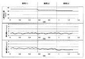
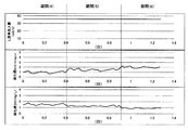
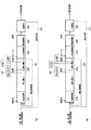
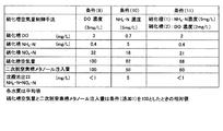
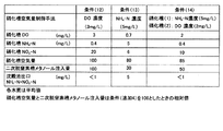
標準脱窒素処理方式や前脱水+標準脱窒素処理方式に本願発明の硝化槽にNH4センサーを設置し、硝化槽のアンモニア性窒素濃度により空気量を制御し、硝化槽のDO値を1mg/L以下とし、硝化槽で硝化反応と脱窒反応が進行し、硝化槽から流出するNH4-N+NOX-N濃度が低減する方法を適用する場合は、硝化槽の機能を分割するとよい。すなわち、図20(a),図21(a)に示すように、硝化槽を硝化槽(1)と硝化槽(2)に機能上の分割を行い、硝化槽(1)を硝化槽のアンモニア性窒素濃度により空気量を制御し、硝化槽のDO値を1mg/L以下とし、硝化槽で硝化反応と脱窒反応が進行することにより硝化槽から流出するNH4-N+NOX-N濃度を低減させる「硝化脱窒同時進行ゾーン」とし、硝化槽(2)をDO値1〜3mg/Lに維持し、ほぼ全てのアンモニア性窒素を硝酸性窒素に酸化させる「硝化ゾーン」とする。硝化槽(2)出口に残留する硝酸性窒素は二次脱窒素槽で脱窒素により除去されるため、放流水の窒素濃度に与える影響は小さくなる。 NH 4 sensor is installed in the nitrification tank of the present invention for standard denitrification treatment method and pre-dehydration + standard denitrification treatment method, the air amount is controlled by ammonia nitrogen concentration in nitrification tank, DO value of nitrification tank is 1 mg / When applying a method in which the nitrification reaction and denitrification reaction proceed in the nitrification tank and the NH 4 -N + NO X -N concentration flowing out of the nitrification tank is reduced, the function of the nitrification tank may be divided. That is, as shown in FIGS. 20 (a) and 21 (a), the nitrification tank is functionally divided into a nitrification tank (1) and a nitrification tank (2), and the nitrification tank (1) is ammonia in the nitrification tank. The amount of air is controlled by the nitrogen concentration, the DO value of the nitrification tank is set to 1 mg / L or less, and the NH 4 -N + NO X -N concentration flowing out of the nitrification tank as the nitrification reaction and denitrification reaction proceed in the nitrification tank The “nitrification denitrification simultaneous progress zone” to be reduced is set as a “nitrification zone” in which the nitrification tank (2) is maintained at a DO value of 1 to 3 mg / L and almost all ammonia nitrogen is oxidized to nitrate nitrogen. Since nitrate nitrogen remaining at the outlet of the nitrification tank (2) is removed by denitrification in the secondary denitrification tank, the influence of the discharged water on the nitrogen concentration is reduced.
硝化槽(1)と硝化槽(2)の分割は、槽が槽壁により区画されている場合および槽の構造上の強度を持たせるための仕切りにより構造上分割されている場合の他、図20(b),図21(b)に示すように、槽壁や仕切りにより構造上分割されていなくても、空気量の調整や散気装置の型式を替えることで、DO濃度の異なるゾーンを形成させることによる機能上の分割でもよい。要は、少なくとも硝化槽を機能上分割する構成であればよい。 The division of the nitrification tank (1) and the nitrification tank (2) is not limited to the case where the tank is partitioned by the tank wall and the case where the tank is structurally divided by a partition for giving structural strength to the tank. 20 (b) and FIG. 21 (b), even if the structure is not divided by tank walls or partitions, zones with different DO concentrations can be obtained by adjusting the air amount or changing the model of the air diffuser. Functional division by forming may be used. In short, it is sufficient that the nitrification tank is functionally divided.
硝化槽(1)と硝化槽(2)の槽容量は、硝化槽(1)<硝化槽(2)でも本願発明の効果を発揮できるが、硝化槽(1)>硝化槽(2)とすることで、本願発明の硝化槽(1)で硝化反応と脱窒反応が同時に進行することによる硝化槽(1)流出のNH4-N+NOX-N濃度を低減させる効果が大きくなるために好ましく、硝化槽(2)は硝化槽(1)の3分の1以下であることがより好ましい。 The tank capacities of the nitrification tank (1) and the nitrification tank (2) can exhibit the effects of the present invention even in the nitrification tank (1) <nitrification tank (2), but the nitrification tank (1)> nitrification tank (2). Therefore, the nitrification reaction and denitrification reaction proceed simultaneously in the nitrification tank (1) of the present invention, which is preferable because the effect of reducing the NH 4 —N + NO X —N concentration in the outflow of the nitrification tank (1) increases. The nitrification tank (2) is more preferably 1/3 or less of the nitrification tank (1).
NH4センサーは硝化槽(1)の末端に設置することが好ましく、DO計は硝化槽(2)に設置することが好ましい。さらに硝化槽(1)にもDO計を設置することがより好ましい。 The NH 4 sensor is preferably installed at the end of the nitrification tank (1), and the DO meter is preferably installed in the nitrification tank (2). It is more preferable to install a DO meter in the nitrification tank (1).
硝化液循環を行う場合には、硝化液を硝化槽(2)から取水することが好ましい。 When performing nitrification liquid circulation, it is preferable to take water from the nitrification tank (2).
浄化槽汚泥の混入比率の高い脱窒素処理方式や前脱水+標準脱窒素処理方式では、生物学的硝化脱窒素処理の前に前処理後のし尿等の濃縮や脱水の固液分離処理を行い、固形物の除去を行う。この固液分離、特に脱水処理では固形物の除去と同時に有機物も除去されるため、固液分離後の分離液では、窒素濃度に対し、脱窒素処理時の水素供与体として使用される有機物が不足し、通常はメタノールなどの水素供与体を脱窒素槽あるいは二次脱窒素槽に過剰に添加することが必要となる。 In the denitrification method with high mixing ratio of septic tank sludge and the pre-dehydration + standard denitrogenation method, concentration of dehydrated human waste after pretreatment and solid-liquid separation treatment of dehydration are performed before biological nitrification denitrification treatment. Remove solids. In this solid-liquid separation, especially dehydration treatment, organic matter is also removed at the same time as removal of solid matter. Therefore, in the separated solution after solid-liquid separation, the organic matter used as a hydrogen donor during denitrogenation treatment is different from the nitrogen concentration. Usually, it is necessary to add an excessive amount of a hydrogen donor such as methanol to the denitrification tank or the secondary denitrification tank.
窒素濃度に対する脱窒素処理時の水素供与体必要量はBOD/N比で示されることが多く、一般的に、BOD/N比が3以上で外部からの水素供与体を供給することなく、生物学的硝化脱窒素処理が行われる。 The amount of hydrogen donor required during the denitrification treatment relative to the nitrogen concentration is often expressed as a BOD / N ratio. Generally, the BOD / N ratio is 3 or more, and there is no need to supply an external hydrogen donor. Nitrification denitrification treatment is performed.
し尿等の脱水後の分離液あるいは、余剰汚泥をし尿等とともに脱水する場合の分離液(以下、両者を合わせて、し尿等の脱水分離液とも記す)では、窒素濃度に対し、脱窒素処理時の水素供与体BOD/N比が3以下、多くの場合は2以下となるため、メタノールなどの水素供与体を過剰に添加することが必要となる。 In the separation liquid after dehydration such as human waste, or the separation liquid in which excess sludge is dehydrated together with urine etc. (hereinafter, both are also referred to as dehydration separation liquid such as human waste) during denitrification treatment with respect to the nitrogen concentration. Since the hydrogen donor BOD / N ratio is 3 or less, and in many cases it is 2 or less, it is necessary to add an excessive amount of hydrogen donor such as methanol.
前脱水+標準脱窒素処理方式に本発明を適用する場合においては、硝化槽で硝化反応と内生脱窒素による脱窒素反応が同時に進行するため、し尿等の脱水分離液のBOD/N比が低い場合でも、硝化槽出口でのNH4-N+NOX-N濃度の低減効果が発揮できるため、従来の前脱水+標準脱窒素処理方式での硝化槽出口のNH4-N+NOX-N窒素濃度低減が可能となり、脱窒素槽あるいは二次脱窒素槽へのメタノールなどの水素供与体添加量を削減することが可能となる。 When the present invention is applied to the pre-dehydration + standard denitrification treatment method, the nitrification reaction and the denitrification reaction by endogenous denitrification proceed simultaneously in the nitrification tank, so the BOD / N ratio of dehydration separation liquid such as human waste is reduced. Even if it is low, the NH 4 -N + NO X -N concentration reduction effect at the nitrification tank outlet can be demonstrated, so the NH 4 -N + NO X -N nitrogen concentration at the nitrification tank outlet in the conventional pre-dehydration + standard denitrification method Therefore, it is possible to reduce the amount of hydrogen donor such as methanol added to the denitrification tank or the secondary denitrification tank.
空気量制御の基準となる硝化槽NH4-N設定値で運転を行っている場合でも、硝化槽のDOが1mg/L以上となることもある。この場合でも、安定した生物学的硝化脱窒処理は行えていて問題はないが、この条件で生物反応槽に流入するし尿等流量を下げることで、生物反応槽の窒素負荷が低減するため、所定の硝化槽NH4-N値で運転するための硝化槽の空気量は低減でき、硝化槽のDOを1mg/L以下に保つことが可能となる。すなわち、生物反応槽に流入するし尿等流量を下げることで、硝化槽NH4-Nを硝化槽NH4-N設定値に保ちながら、硝化槽のDOを1mg/L以下にすることができ、硝化槽で硝化反応と脱窒反応を進行させることができ、硝化槽から流出するNH4-N+NOX-N濃度を低減することが可能となる。 Even when operating with the nitrification tank NH 4 -N set value, which is the standard for air volume control, DO in the nitrification tank may be 1 mg / L or more. Even in this case, stable biological nitrification denitrification treatment can be performed, but there is no problem, but the nitrogen load in the biological reaction tank is reduced by reducing the flow rate of urine and the like flowing into the biological reaction tank under these conditions, The amount of air in the nitrification tank for operation at a predetermined nitrification tank NH 4 -N value can be reduced, and DO in the nitrification tank can be kept at 1 mg / L or less. That is, by reducing the flow rate of urine and the like flowing into the biological reaction tank, while maintaining the nitrification tank NH 4 -N at the nitrification tank NH 4 -N set value, the DO of the nitrification tank can be reduced to 1 mg / L or less, The nitrification reaction and denitrification reaction can proceed in the nitrification tank, and the concentration of NH 4 —N + NO X —N flowing out from the nitrification tank can be reduced.
また、空気量制御の基準となる硝化槽NH4-N設定値(1)よりも高い硝化槽NH4-N設定値(2)を設定し、硝化槽NH4-N設定値(1)で運転している状況で硝化槽DOが1mg/L以上の場合、硝化槽NH4-N設定値を硝化槽NH4-N設定値(2)に変更することで、所定の硝化槽NH4-N値で運転するための硝化槽の空気量は低減でき、硝化槽のDOを1mg/L以下に保つことが可能となる。そのため、硝化槽NH4-Nを硝化槽NH4-N設定値に保ちながら、硝化槽のDOを1mg/L以下にすることができ、硝化槽で硝化反応と脱窒反応が進行するため、硝化槽から流出するNH4-N+NOX-N濃度を低減することが可能となる。ここでは、硝化槽NH4-N設定を二段階として説明したが、硝化槽NH4-N設定値を三段階以上の複数段階設定することも可能である。 Also, set the nitrification tank NH 4 -N set value (2) higher than the nitrification tank NH 4 -N set value (1), which is the reference for air volume control, and set the nitrification tank NH 4 -N set value (1). If a situation you are driving nitrification DO is equal to or greater than 1 mg / L, by changing the nitrification tank NH 4 -N settings to nitrification tank NH 4 -N setpoint (2), a predetermined nitrification tank NH 4 - The amount of air in the nitrification tank for operation at N value can be reduced, and the DO in the nitrification tank can be kept below 1 mg / L. Therefore, while keeping the nitrification tank NH 4 -N at the nitrification tank NH 4 -N set value, DO of the nitrification tank can be 1 mg / L or less, and the nitrification reaction and denitrification reaction proceed in the nitrification tank. It becomes possible to reduce the concentration of NH 4 —N + NO X —N flowing out of the nitrification tank. Here, the nitrification tank NH 4 -N setting has been described as two stages, but the nitrification tank NH 4 -N set value can be set in multiple stages of three or more stages.
本願発明全般において、硝化槽のNH4-N設定値は、放流水水質、空気量削減効果、硝化槽内の撹拌状況、硝化槽DO値、メタノール使用量削減効果等を考慮した上で適宜設定することが好ましい。 In the present invention in general, the NH 4 -N set value for the nitrification tank is set appropriately in consideration of the quality of the discharged water, the air volume reduction effect, the stirring status in the nitrification tank, the nitrification tank DO value, the methanol usage reduction effect, etc. It is preferable to do.
以下、本発明を実施例により具体的に説明するが、本発明はこれら実施例によって限定されるものではない。 EXAMPLES The present invention will be specifically described below with reference to examples, but the present invention is not limited to these examples.
<事前検討1:NH4センサーの性能測定>
前処理後のし尿等を前記図7に示す膜分離高負荷脱窒素処理方式で処理した際のNH4センサー測定値について検討した。
<Preliminary study 1: NH 4 sensor performance measurement>
The NH 4 sensor measured value when human waste after pretreatment was treated by the membrane separation high load denitrogenation method shown in FIG. 7 was examined.
被処理水の主な水質(平均値)は、NH4-N:1,000mg/L、BOD:4,000mg/Lであった。また流入水量は30m3/d、硝化液循環量は600m3/dとした。また硝化槽270のMLSSは12,000mg/L、硝化槽水温は35℃とした。硝化槽270のNH4センサー100により、NH4-Nを測定し、別途実施した水質分析結果と比較した。この時の硝化槽270内の溶解性蒸発残留物濃度は2,000〜4,000mg/L、カリウムイオン濃度は150〜350mg/Lであった。図12は前記NH4センサー測定値と水質分析結果の比較を示す図である。同図に示すように、NH4センサー測定値と水質分析結果はほぼ一致していることから、前記図1〜図5に示すNH4センサー100が、溶解性蒸発残留物濃度およびK+濃度の高い廃水に適用可能であることを確認した。 The main water quality (average value) of treated water was NH 4 -N: 1,000 mg / L, BOD: 4,000 mg / L. The amount of inflow water was 30 m 3 / d, and the nitrification liquid circulation rate was 600 m 3 / d. The MLSS of the nitrification tank 270 was 12,000 mg / L, and the nitrification tank water temperature was 35 ° C. NH 4 —N was measured by the NH 4 sensor 100 in the nitrification tank 270 and compared with the results of water quality analysis performed separately. At this time, the concentration of the soluble evaporation residue in the nitrification tank 270 was 2,000 to 4,000 mg / L, and the potassium ion concentration was 150 to 350 mg / L. FIG. 12 is a diagram showing a comparison between NH 4 sensor measurement values and water quality analysis results. As shown in the figure, since the NH 4 sensor measurement value and the water quality analysis result are almost the same, the NH 4 sensor 100 shown in FIGS. 1 to 5 has a high concentration of soluble evaporation residue and K + concentration. It was confirmed that it can be applied to wastewater.
<事前検討2:NH4センサーの性能測定>
事前検討1と同様に、前処理後のし尿等を前記図7に示す膜分離高負荷脱窒素処理方式で処理した際の、溶解性残留物濃度およびK+濃度の高い廃水でのNH4センサー100の適用について検討した。即ち、下記するA処理場、B処理場、C処理場において、硝化槽270のNH4センサー100により、NH4-Nを測定し、別途実施した水質分析結果と比較した。
A処理場:事前検討1と同じし尿処理施設、硝化槽270の溶解性蒸発残留物濃度は2,000〜4,000mg/L、カリウムイオン濃度は150〜350mg/L
B処理場:し尿処理施設、硝化槽の溶解性蒸発残留物濃度は3,000〜6,000mg/L、カリウムイオン濃度は300〜450mg/L
C処理場:最終処分場浸出水処理施設、硝化槽の溶解性蒸発残留物濃度は10,000〜20,000mg/L、カリウムイオン濃度は10〜40mg/L
<Preliminary study 2: NH 4 sensor performance measurement>
Similar to the preliminary study 1, the NH 4 sensor 100 in waste water with a high concentration of soluble residue and K + when the human waste after pretreatment is treated by the membrane separation high-load denitrogenation method shown in FIG. The application of was examined. That is, NH 4 -N was measured by the NH 4 sensor 100 in the nitrification tank 270 in the following A treatment plant, B treatment plant, and C treatment plant, and compared with the results of water quality analysis performed separately.
A treatment plant: Same as previous study 1, sewage treatment facility, soluble evaporation residue concentration in nitrification tank 270 is 2,000-4,000mg / L, potassium ion concentration is 150-350mg / L
B Treatment Plant: Dissolved evaporation residue concentration in human waste treatment facility and nitrification tank is 3,000-6,000mg / L, potassium ion concentration is 300-450mg / L
C treatment plant: Final disposal site leachate treatment facility, soluble evaporation residue concentration in nitrification tank is 10,000-20,000mg / L, potassium ion concentration is 10-40mg / L
その結果を図13に示す。同図に示すように、A処理場、B処理場、C処理場共にNH4センサー測定値と水質分析結果はほぼ一致していた。カリウムイオン濃度の高いB処理場ではNH4-Nが5mg/L以下で、NH4-Nセンサー測定値が高い値を示す傾向にあったが、運転管理上は支障のない範囲であった。これによって、前記図1〜図5に示すNH4センサー100が、溶解性蒸発残留物濃度およびK+濃度の高い廃水に適用可能であることを確認した。 The result is shown in FIG. As shown in the figure, the NH 4 sensor measurement values and the water quality analysis results were almost the same for the A treatment plant, the B treatment plant, and the C treatment plant. In the B treatment plant with a high potassium ion concentration, NH 4 -N was 5 mg / L or less, and the NH 4 -N sensor measured value tended to show a high value. Thus, it was confirmed that the NH 4 sensor 100 shown in FIGS. 1 to 5 can be applied to waste water having a high concentration of soluble evaporation residue and a high K + concentration.
<実施例1:硝化槽NH4-N濃度による空気量制御の一例>
前処理後のし尿および浄化槽汚泥を、前記図6に示す標準脱窒素処理方式で処理した。NH4-N濃度の測定は、前記図1〜図5に示すNH4センサー100を用いた。被処理水(対象水)の主な水質(平均値)はNH4-N:500mg/L、BOD:2,000mg/Lであった。また流入水量は60m3/d、希釈水量は140m3/d、硝化液循環量は300m3/d、返送汚泥量は200m3/dとした。硝化槽220のMLSSを6,000mg/L、硝化槽水温を29〜31℃に設定した。そして、硝化槽220のNH4センサー100で硝化槽220のNH4-Nを1mg/Lとなるように硝化槽220への空気量を制御した。
<Example 1: Example of air amount control by NH 4 -N concentration in nitrification tank>
The pre-treated human waste and septic tank sludge were treated by the standard denitrification method shown in FIG. The NH 4 -N concentration was measured using the NH 4 sensor 100 shown in FIGS. Main water quality (average value) of treated water (target water) was NH 4 -N: 500 mg / L, BOD: 2,000 mg / L. The inflow water volume was 60 m 3 / d, the dilution water volume was 140 m 3 / d, the nitrification liquid circulation volume was 300 m 3 / d, and the return sludge volume was 200 m 3 / d. MLSS of nitrification tank 220 was set to 6,000 mg / L, and nitrification tank water temperature was set to 29 to 31 ° C. The amount of air to the nitrification tank 220 was controlled by the NH 4 sensor 100 of the nitrification tank 220 so that NH 4 —N in the nitrification tank 220 was 1 mg / L.
図14は、NH4センサー100を使用したNH4-N濃度による空気量制御運転の結果を示す図である。同図に示すように、NH4センサー100を使用したNH4-N濃度による空気量制御運転の結果は、硝化槽NH4-N:0.6〜1.3mg/L(平均1.0mg/L)、硝化槽DO:0.7〜1.8(平均0.9mg/L)であった。このことから、NH4センサー100を使用したNH4-N濃度による空気量制御運転を行うことで、従来法よりも低いDO値、すなわち少ない空気量で硝化槽220での良好な硝化反応の進行が達成できることを確認した。 FIG. 14 is a diagram showing the result of the air amount control operation based on the NH 4 —N concentration using the NH 4 sensor 100. As shown in the figure, the results of the air volume control operation by NH 4 -N concentration using the NH 4 sensor 100 are nitrification tank NH 4 -N: 0.6 to 1.3 mg / L (average 1.0 mg / L), nitrification Tank DO: 0.7 to 1.8 (average 0.9 mg / L). From this, by performing the air amount control operation by NH 4 -N concentration using the NH 4 sensor 100, the progress of a good nitrification reaction in the nitrification tank 220 with a DO value lower than the conventional method, that is, a small air amount. Confirmed that can be achieved.
<実施例2:硝化槽NH4-N濃度と硝化槽DO濃度による空気量制御の比較>
硝化槽NH4-N濃度による空気量制御(本願発明)と硝化槽DO濃度による空気量制御(従来法)での比較を行った。
<Example 2: Comparison of air amount control by nitrification tank NH 4 -N concentration and nitrification tank DO concentration>
A comparison was made between air quantity control by the nitrification tank NH 4 -N concentration (the present invention) and air quantity control by the nitrification tank DO concentration (conventional method).
前処理後のし尿および浄化槽汚泥を、前記図6に示す標準脱窒素処理方式で処理した。被処理液(対象水)の主な水質(平均値)は、NH4-N:500mg/L、BOD:2,000mg/Lであった。また流入水量は60m3/d、希釈水量は140m3/d、硝化液循環量は300m3/d、返送汚泥量は200m3/dとした。硝化槽220のMLSSを6,000mg/L、硝化槽水温を29〜31℃とした。 The pre-treated human waste and septic tank sludge were treated by the standard denitrification method shown in FIG. The main water quality (average value) of the liquid to be treated (target water) was NH 4 -N: 500 mg / L, and BOD: 2,000 mg / L. The inflow water volume was 60 m 3 / d, the dilution water volume was 140 m 3 / d, the nitrification liquid circulation volume was 300 m 3 / d, and the return sludge volume was 200 m 3 / d. The MLSS of the nitrification tank 220 was 6,000 mg / L, and the nitrification tank water temperature was 29 to 31 ° C.
図15は、硝化槽NH4-N濃度による空気量制御と、硝化槽DO濃度による空気量制御の結果を比較して示す図である。同図に示す条件(1)は前記実施例1の結果であり、硝化槽220のNH4センサー100で硝化槽220のNH4-N濃度が1mg/Lとなるように硝化槽220への空気量を制御した際の各種数値の測定結果を示している。同様に本願発明による条件(2)では、硝化槽220のNH4-N濃度が2mg/Lとなるように硝化槽220への空気量を制御した際の各種数値の測定結果を示している。一方、従来法による条件(3)では、硝化槽220のDO値を2mg/Lに設定し、空気量を制御した際の各種数値の測定結果を示している。また、比較条件となる条件(4)は、硝化槽220のDO値を0.9mg/Lに設定し、空気量を制御した際の各種数値の測定結果を示している。なお、NH4センサー100、DO計223は各条件において同一箇所に設置した。 FIG. 15 is a diagram comparing the results of air amount control based on the nitrification tank NH 4 -N concentration and air amount control based on the nitrification tank DO concentration. The condition (1) shown in the figure is the result of Example 1, and the air to the nitrification tank 220 is adjusted so that the NH 4 -N concentration in the nitrification tank 220 becomes 1 mg / L by the NH 4 sensor 100 in the nitrification tank 220. The measurement results of various values when the amount is controlled are shown. Similarly, the condition (2) according to the present invention shows the measurement results of various numerical values when the amount of air to the nitrification tank 220 is controlled so that the NH 4 —N concentration in the nitrification tank 220 is 2 mg / L. On the other hand, the condition (3) according to the conventional method shows measurement results of various values when the DO value of the nitrification tank 220 is set to 2 mg / L and the air amount is controlled. Condition (4) as a comparison condition shows measurement results of various values when the DO value of the nitrification tank 220 is set to 0.9 mg / L and the air amount is controlled. The NH 4 sensor 100 and the DO meter 223 were installed at the same location under each condition.
図15に示すように、条件(1)、条件(3)の硝化槽NH4-N濃度は概ね1mg/L以下であり、良好な硝化の進行が確認できた。条件(3)では空気量不足のため、NH4-Nが残留する場合があった。条件(4)では平均値で6mg/Lであるが、最大30mg/Lにも達し、処理水質の悪化を招いた。条件(2)では硝化槽NH4-N濃度は設定値通りの2mg/Lであった。硝化槽NH4-Nが2mg/Lで安定していたため、放流水水質基準値は十分に満足できる。硝化槽220の空気量は条件(1)では条件(3)に比べ、約1割少なくなっていた。硝化槽NOX-Nは条件(1)および条件(2)では条件(3)よりも低い値であった。これはDO値が平均で0.8〜0.9mg/Lと低めであったことから、硝化槽220での硝化脱窒素同時進行の効果であると考えられる。また、条件(1)に比べ硝化槽220のNH4-N設定値を高めた条件(2)では、硝化槽空気量が少なく、硝化槽DOが低くなっていた。条件(1)に比べ硝化槽DOが低くなった条件(2)では、より脱窒素反応が進みやすくなったため、硝化槽NOX-Nの値が低くなった。また、条件(1)では硝化槽DO値が0.7〜1.8mg/Lであり、硝化槽220のDO値が常時1mg/L以下でなくても、期間中の平均値として硝化槽220での硝化脱窒素同時進行を確認できた。硝化槽220のNOX-Nが低い条件(1)および条件(2)では二次脱窒素槽230でのメタノール使用量が少なくなるため、薬品コスト低減が可能となる。 As shown in FIG. 15, the nitrification tank NH 4 -N concentration in the conditions (1) and (3) was approximately 1 mg / L or less, and favorable nitrification progress was confirmed. Under condition (3), NH 4 -N may remain due to insufficient air volume. In condition (4), the average value was 6 mg / L, but it reached 30 mg / L at the maximum, resulting in deterioration of treated water quality. Under condition (2), the concentration of the nitrification tank NH 4 -N was 2 mg / L as set. Since the nitrification tank NH 4 -N was stable at 2 mg / L, the effluent water quality standard was sufficiently satisfied. The amount of air in the nitrification tank 220 was about 10% less in the condition (1) than in the condition (3). The nitrification tank NO x -N was lower in the conditions (1) and (2) than in the condition (3). This is considered to be due to the simultaneous progress of nitrification and denitrification in the nitrification tank 220 since the DO value was a low 0.8 to 0.9 mg / L on average. Further, in the condition (2) in which the NH 4 -N set value of the nitrification tank 220 was increased compared to the condition (1), the amount of nitrification tank air was small and the nitrification tank DO was low. In the condition (2) in which the nitrification tank DO was lower than in the condition (1), the denitrification reaction was easier to proceed, so the value of the nitrification tank NO x -N was lowered. In condition (1), the nitrification tank DO value is 0.7 to 1.8 mg / L, and even if the DO value of the nitrification tank 220 is not always 1 mg / L or less, the nitrification in the nitrification tank 220 is an average value during the period. Simultaneous progress of denitrification could be confirmed. Under the conditions (1) and (2) where NO X -N in the nitrification tank 220 is low, the amount of methanol used in the secondary denitrification tank 230 is reduced, so that the chemical cost can be reduced.
<実施例3:硝化槽NH4-N濃度と硝化槽DO濃度による空気量制御の比較>
図7に示す方式(膜分離高負荷脱窒素処理方式・高負荷脱窒素処理方式)のように、NH4センサー100を設置した硝化槽270の後段に二次硝化槽290および二次脱窒素槽300を備えたフローでは、硝化槽270のNH4-N設定値を高めても、硝化槽出口で残留しているNH4-Nが後段の二次硝化槽290および二次脱窒素槽300で除去されるため放流水水質に与える影響が小さい。
<Example 3: Comparison of air amount control by nitrification tank NH 4 -N concentration and nitrification tank DO concentration>
Like the method shown in FIG. 7 (membrane separation high load denitrification treatment method / high load denitrification treatment method), the secondary nitrification tank 290 and the secondary denitrification tank are arranged at the subsequent stage of the nitrification tank 270 where the NH 4 sensor 100 is installed. in the flow equipped with 300, with NH 4 be enhanced -N setpoint, NH 4 -N is in the subsequent stage the secondary nitrification tank 290 and secondary denitrification tank 300 remaining in the nitrification tank outlet of the nitrification tank 270 Since it is removed, the impact on the quality of discharged water is small.
そしてこの実施例3では、図7に示す処理フローにおいて、硝化槽270のNH4-N設定値による硝化槽水質および硝化槽空気量について比較した。前記事前検討1と同じ運転条件で、図16に示す条件(5)〜(7)はNH4-N濃度による空気量制御(本願発明)での測定結果を、条件(8)はDO濃度による空気量制御(従来法)での測定結果を示している。同図に示すように、条件(5)〜(7)では、条件(8)に比べ硝化槽NH4-N+NOX-N濃度が低くなっていた。DO値が低めであったことから、硝化槽270での硝化脱窒素同時進行の効果であると考えられる。硝化槽NH4-N+NOX-N濃度を低減する最適硝化槽NH4-Nが存在することが示唆された。硝化槽のNH4-N+NOX-Nを低減することで二次脱窒素槽300でのメタノール使用量を少なくすることができる。 In Example 3, the nitrification tank water quality and the nitrification tank air amount according to the NH 4 -N set value of the nitrification tank 270 were compared in the processing flow shown in FIG. Under the same operating conditions as in the previous study 1, the conditions (5) to (7) shown in FIG. 16 are the measurement results in the air amount control by the NH 4 -N concentration (the present invention), and the condition (8) is the DO concentration. The measurement result in the air amount control (conventional method) by the is shown. As shown in the figure, in the conditions (5) to (7), the concentration of the nitrification tank NH 4 —N + NO X —N was lower than that in the condition (8). Since DO value was low, it is thought that it is an effect of simultaneous nitrification denitrification in the nitrification tank 270. It was suggested that there exists an optimal nitrification tank NH 4 -N that reduces the concentration of nitrification tank NH 4 -N + NO X -N. By reducing NH 4 —N + NO X —N in the nitrification tank, the amount of methanol used in the secondary denitrification tank 300 can be reduced.
<実施例4>
前処理後のし尿等を、図7に示す膜分離高負荷脱窒素処理方式で処理するA処理場で、下記するケース1,2の条件で運転した。対象水の主な水質(平均値)はNH4-N:1,000mg/L、BOD:4,000mg/Lであった。流入水量は36m3/d、硝化液循環量は720m3/dとした。硝化槽270のMLSSは12,000mg/L、硝化槽水温は35℃とした。硝化槽270のNH4センサー100で硝化槽270のNH4-Nが1mg/Lとなるように硝化槽270への空気量を制御したところ、硝化槽270のDO値は約1.5mg/Lであった。
<Example 4>
The pre-treated human waste and the like were operated under the conditions of cases 1 and 2 described below in the A treatment plant where the membrane separation high-load denitrogenation treatment method shown in FIG. The main water quality (average value) of the target water was NH 4 -N: 1,000 mg / L and BOD: 4,000 mg / L. The amount of inflow water was 36 m 3 / d, and the nitrification liquid circulation rate was 720 m 3 / d. The MLSS of the nitrification tank 270 was 12,000 mg / L, and the nitrification tank water temperature was 35 ° C. When the amount of air to the nitrification tank 270 is controlled by the NH 4 sensor 100 of the nitrification tank 270 so that NH 4 -N of the nitrification tank 270 becomes 1 mg / L, the DO value of the nitrification tank 270 is about 1.5 mg / L. there were.
ケース1:生物反応槽に流入するし尿等の流量を下げて、硝化槽270のDO値を1mg/L以下に設定した場合
図17に示すように、硝化槽270のNH4-N設定値は1mg/Lで変更せず、生物反応槽に流入するし尿等の流量を期間(1):36m3/d、期間(2)33m3/d、期間(3)32m3/dで段階的に下げることで、硝化槽270のDO値を1mg/L以下に維持する運転を行った。硝化液循環量は生物反応槽に流入するし尿等の流量の20倍とした。硝化槽270のDO値は期間(1)で約1.5mg/L、期間(2)で1.1〜1.3mg/L、期間(3)で0.7〜1.0mg/Lであり、期間(3)で硝化槽のDO値を1mg/L以下に維持することができた。期間(3)では硝化槽270での硝化と脱窒素の同時進行によるNH4-N+NOX-Nの低減効果が期待できる。
Case 1: When the flow rate of human urine flowing into the biological reaction tank is lowered and the DO value of the nitrification tank 270 is set to 1 mg / L or less, as shown in FIG. 17, the NH 4 -N setting value of the nitrification tank 270 is Without changing at 1 mg / L, the flow rate of human urine flowing into the biological reaction tank is phased in period (1): 36 m 3 / d, period (2) 33 m 3 / d, period (3) 32 m 3 / d By lowering, the DO value of the nitrification tank 270 was maintained at 1 mg / L or less. The nitrification liquid circulation rate was set to 20 times the flow rate of urine flowing into the biological reaction tank. The DO value of the nitrification tank 270 is about 1.5 mg / L in the period (1), 1.1 to 1.3 mg / L in the period (2), 0.7 to 1.0 mg / L in the period (3), and nitrification in the period (3) The DO value of the tank could be maintained below 1 mg / L. In the period (3), a reduction effect of NH 4 —N + NO X —N can be expected by simultaneous progress of nitrification and denitrification in the nitrification tank 270.
ケース2:硝化槽270のNH4-N設定値を上げて、硝化槽270のDO値を1mg/L以下に設定した場合
図18に示すように、生物反応槽に流入するし尿等の流量は変更せず、硝化槽270のNH4-N設定値を、期間(4):1mg/L、期間(5)1.5mg/L、期間(6)2mg/Lで段階的に上げることで、硝化槽270のDO値を1mg/L以下に維持する運転を行った。硝化槽270のDO値は期間(4)で約1.5mg/L、期間(5)で1.1〜1.4mg/L、期間(6)で0.7〜1.0mg/Lであり、期間(6)で硝化槽のDO値を1mg/L以下に維持することができた。期間(6)では硝化槽270での硝化と脱窒素の同時進行によるNH4-N+NOX-Nの低減効果が期待できる。
Case 2: When the NH 4 -N setting value of the nitrification tank 270 is increased and the DO value of the nitrification tank 270 is set to 1 mg / L or less, as shown in FIG. By changing the NH 4 -N set value in the nitrification tank 270 in stages (4): 1 mg / L, period (5) 1.5 mg / L, period (6) 2 mg / L without change, nitrification The operation of maintaining the DO value of the tank 270 at 1 mg / L or less was performed. The DO value of the nitrification tank 270 is about 1.5 mg / L in the period (4), 1.1 to 1.4 mg / L in the period (5), 0.7 to 1.0 mg / L in the period (6), and nitrified in the period (6). The DO value of the tank could be maintained below 1 mg / L. In the period (6), it can be expected that NH 4 —N + NO X —N is reduced by simultaneous nitrification and denitrification in the nitrification tank 270.
<実施例5>
標準脱窒素処理方式での、硝化槽DO濃度による空気量制御(従来法)、硝化槽NH4-N濃度による空気量制御(本願発明、図6参照)、および硝化槽をDO濃度により機能上、「硝化脱窒同時進行ゾーン」と「硝化ゾーン」とに分割する空気量制御手法(本願発明、図20参照)とでの比較を行った。
<Example 5>
In the standard denitrification system, the air volume control by the nitrification tank DO concentration (conventional method), the air volume control by the nitrification tank NH 4 -N concentration (refer to the present invention, FIG. 6), and the nitrification tank functionally by the DO concentration Comparison was made with an air amount control method (refer to the present invention, see FIG. 20) that is divided into a “nitrification / denitrification simultaneous progress zone” and a “nitrification zone”.
前処理後のし尿および浄化槽汚泥を、前記図6に示す標準脱窒素処理方式で処理した。被処理水(対象水)の主な水質(平均値)はNH4-N:500mg/L、BOD:2,000mg/Lであった。また流入水量は50m3/d、希釈水量は140m3/d、硝化液循環量は300m3/d、返送汚泥量は200m3/dとした。硝化槽220のMLSSを6,000mg/L、硝化槽水温を29〜31℃に設定した。NH4-N濃度の測定は、前記図1〜図5に示すNH4センサー100を用いた。 The pre-treated human waste and septic tank sludge were treated by the standard denitrification method shown in FIG. Main water quality (average value) of treated water (target water) was NH 4 -N: 500 mg / L, BOD: 2,000 mg / L. The inflow water volume was 50 m 3 / d, the dilution water volume was 140 m 3 / d, the nitrification liquid circulation volume was 300 m 3 / d, and the return sludge volume was 200 m 3 / d. MLSS of nitrification tank 220 was set to 6,000 mg / L, and nitrification tank water temperature was set to 29 to 31 ° C. The NH 4 -N concentration was measured using the NH 4 sensor 100 shown in FIGS.
従来法の条件(9)では硝化槽のDOが3mg/Lになるように硝化槽の空気量を設定した。 In the condition (9) of the conventional method, the air amount of the nitrification tank was set so that DO of the nitrification tank was 3 mg / L.
条件(10)では硝化槽のNH4-N濃度が5mg/Lになるように空気量を調整した。 In condition (10), the amount of air was adjusted so that the NH 4 —N concentration in the nitrification tank was 5 mg / L.
条件(11)では、硝化槽の前半約3分の2を「硝化脱窒同時進行ゾーン」(以下、硝化槽(1)とも記す)として、硝化槽(1)末端部のNH4-N濃度が5mg/Lになるように空気量を調整し、硝化槽の後半約3分の1を「硝化ゾーン」(以下、硝化槽(2)とも記す)として、硝化槽(2)のDOが2mg/Lになるように調整した。硝化槽(1)と硝化槽(2)は、図20(b)に示すように、構造上の区切りや仕切りは無く、空気量の違いによる機能上の分割とした。 In condition (11), the NH 4 -N concentration at the end of the nitrification tank (1) is defined as about 2/3 of the first half of the nitrification tank as a “nitrification denitrification simultaneous progress zone” (hereinafter also referred to as nitrification tank (1)). The air volume is adjusted so that it becomes 5 mg / L, and about 1/3 of the latter half of the nitrification tank is designated as the “nitrification zone” (hereinafter also referred to as nitrification tank (2)), and the DO in the nitrification tank (2) is 2 mg. Adjusted to be / L. As shown in FIG. 20B, the nitrification tank (1) and the nitrification tank (2) have no structural divisions or partitions and are functionally divided according to the difference in the amount of air.
条件(9)では硝化槽にDO計を設置した。条件(10)では、図6に示すように、硝化槽にNH4センサーを設置した。条件(11)では、図20(b)に示すように、硝化槽(1)にNH4センサーを、硝化槽(2)にDO計を設置した。条件(10)と条件(11)ではNH4センサーの設置個所にDO計も設置してDOを監視した。 In condition (9), a DO meter was installed in the nitrification tank. In condition (10), as shown in FIG. 6, an NH 4 sensor was installed in the nitrification tank. In condition (11), as shown in FIG. 20B, an NH 4 sensor was installed in the nitrification tank (1), and a DO meter was installed in the nitrification tank (2). Under conditions (10) and (11), a DO meter was also installed at the location where the NH 4 sensor was installed to monitor DO.
硝化槽出口NOX-Nはその大部分がNO3-Nであったため、二次脱窒素槽へのメタノール注入量は硝化槽出口NO3-N濃度に応じて設定した。 Since most of the nitrification tank outlet NO X -N was NO 3 -N, the amount of methanol injected into the secondary denitrification tank was set according to the nitrification tank outlet NO 3 -N concentration.
硝化槽出口に設置した硝酸センサーの測定値から、NO3-Nの3倍量となるようにメタノールを二次脱窒素槽に注入した。 From the measured value of the nitric acid sensor installed at the nitrification tank outlet, methanol was injected into the secondary denitrification tank so as to be 3 times the amount of NO 3 -N.
運転結果を図22に示す。硝化槽の空気量をNH4センサーの設定値により実施した本願発明の条件(10)および条件(11)では、硝化槽での硝化脱窒素同時進行の効果により、硝化槽出口のNH4-N+NOX-N濃度が従来法の条件(9)の約6割に低減した。条件(10)の硝化槽のDOは平均で0.7mg/Lであり、概ね1mg/L以下であった。条件(11)の硝化槽(1)のDOは平均で0.8mg/Lであり、概ね1mg/L以下であった。硝化槽出口のNOX-N濃度低減が可能となった条件(10)および条件(11)では、従来法の条件(9)に比べ、二次脱窒素槽のメタノール注入量を50〜60%に削減可能であった。 An operation result is shown in FIG. In the conditions (10) and (11) of the present invention in which the amount of air in the nitrification tank was set according to the set value of the NH 4 sensor, NH 4 -N at the nitrification tank outlet was obtained due to the effect of simultaneous nitrification and denitrification in the nitrification tank. The + NO X -N concentration was reduced to about 60% of the condition (9) of the conventional method. The DO of the nitrification tank of condition (10) was 0.7 mg / L on average and was generally 1 mg / L or less. The DO of the nitrification tank (1) under condition (11) was 0.8 mg / L on average, and was generally 1 mg / L or less. In conditions (10) and (11) where the NO X -N concentration at the nitrification tank outlet can be reduced, the amount of methanol injected into the secondary denitrification tank is 50-60% compared to condition (9) of the conventional method. It was possible to reduce it.
なお、硝化槽のNH4-N濃度を5mg/Lに設定した条件(10)では硝化槽出口に残留するNH4-Nが二次脱窒素槽で除去されず、再曝気槽でNH4-Nの一部あるいは全部がNOX-Nに硝化された状態で沈殿池出口に残留するため、このNH4-N+NOX-N濃度の分だけ、放流水窒素濃度を高める可能性がある。 Incidentally, NH 4 -N remaining NH 4 nitrification tank outlet in conditions of -N concentration was set to 5mg / L (10) of the nitrification tank is not removed by the secondary denitrification tank, NH 4 re aeration tank - Since some or all of N remains nitrified to NO X -N and remains at the sedimentation basin outlet, there is a possibility of increasing the concentration of discharged water nitrogen by this NH 4 -N + NO X -N concentration. .
一方、硝化槽の後半約3分の1を硝化ゾーンに設定した条件(11)では、硝化槽出口でのNH4-Nの残留が極めて少なく、沈殿池出口でのNH4-N+NOX-Nは1mg/L以下であり、良好な窒素除去が達成できた。 On the other hand, in the condition (11) in which about one third of the latter half of the nitrification tank is set as the nitrification zone, there is very little NH 4 —N remaining at the nitrification tank outlet, and NH 4 —N + NO X at the precipitation basin outlet. -N was 1 mg / L or less, and good nitrogen removal was achieved.
<実施例6>
前脱水+標準脱窒素処理方式での、硝化槽DO濃度による空気量制御(従来法)、硝化槽NH4-N濃度による空気量制御(本願発明、図8参照)、および硝化槽をDO濃度により機能上、「硝化脱窒同時進行ゾーン」と「硝化ゾーン」とに分割する空気量制御手法(本願発明、図21参照)とでの比較を行った。
<Example 6>
Air volume control based on nitrification tank DO concentration (conventional method), air volume control based on nitrification tank NH 4 -N concentration (refer to the present invention, see FIG. 8), and nitrification tank DO concentration Thus, a functional comparison was made with the air amount control method (refer to the present invention, see FIG. 21) that is divided into a “nitrification / denitrification simultaneous progress zone” and a “nitrification zone”.
前処理後のし尿および浄化槽汚泥を、前記図8に示す前脱水+標準脱窒素処理方式で処理した。し尿等に生物処理で発生した余剰汚泥を加えた混合汚泥を高分子凝集剤で凝集した後、スクリュープレス脱水機で脱水した脱水分離液を対象に従来法と本願発明の比較を行った。被処理水であるし尿等の脱水分離液の主な水質(平均値)はNH4-N:400mg/L、BOD:700mg/Lであった。今回の処理対象であるし尿等の脱水分離液のBOD/NH4-N比は1.75であり、窒素濃度に対し、脱窒素処理時の水素供与体として使用される有機物が不足しているため、メタノールを二次脱窒素槽に過剰に添加することが必要となる。また流入水量は50m3/d、雑排水は10m3/d、硝化液循環量は600m3/d、返送汚泥量は200m3/dとした。硝化槽350のMLSSを6,000mg/L、硝化槽水温を31〜33℃に設定した。NH4-N濃度の測定は、前記図1〜図5に示すNH4センサー100を用いた。 The pre-treated human waste and septic tank sludge were treated by the pre-dehydration + standard denitrogenation method shown in FIG. A comparison between the conventional method and the present invention was made on a dehydrated separation liquid obtained by aggregating mixed sludge obtained by adding surplus sludge generated by biological treatment to human waste or the like with a polymer flocculant and then dewatering with a screw press dehydrator. The main water quality (average value) of dehydrated separation liquid such as human waste, which is the water to be treated, was NH 4 -N: 400 mg / L, BOD: 700 mg / L. The BOD / NH 4 -N ratio of the dehydration separation liquid such as human waste, which is the subject of treatment this time, is 1.75, and the organic matter used as a hydrogen donor during denitrification is insufficient with respect to the nitrogen concentration. It is necessary to add methanol in excess to the secondary denitrification tank. The inflow water volume was 50 m 3 / d, miscellaneous wastewater was 10 m 3 / d, the nitrification liquid circulation volume was 600 m 3 / d, and the return sludge volume was 200 m 3 / d. MLSS of nitrification tank 350 was set to 6,000 mg / L, and nitrification tank water temperature was set to 31 to 33 ° C. The NH 4 -N concentration was measured using the NH 4 sensor 100 shown in FIGS.
従来法の条件(12)では硝化槽のDOが3mg/Lになるように硝化槽の空気量を設定した。 In the condition (12) of the conventional method, the amount of air in the nitrification tank was set so that DO in the nitrification tank was 3 mg / L.
条件(13)では硝化槽のNH4-N濃度が5mg/Lになるように空気量を調整した。 In condition (13), the amount of air was adjusted so that the NH 4 —N concentration in the nitrification tank was 5 mg / L.
条件(14)では、硝化槽の前半約3分の2を「硝化脱窒同時進行ゾーン」の硝化槽(1)とし、硝化槽(1)のNH4-N濃度が5mg/Lになるように空気量を調整し、硝化槽の後半約3分の1を「硝化ゾーン」の硝化槽(2)とし、硝化槽(2)のDOが2mg/Lになるように調整した。硝化槽(1)と硝化槽(2)は、図21(b)に示すように、構造上の区切りや仕切りは無く、空気量の違いによる機能上の分割とした。 In condition (14), about 2/3 of the first half of the nitrification tank is used as the nitrification tank (1) in the “simultaneous nitrification and denitrification zone” so that the NH 4 -N concentration in the nitrification tank (1) is 5 mg / L. The amount of air was adjusted so that about one third of the latter half of the nitrification tank was used as the nitrification tank (2) in the “nitrification zone” and the DO in the nitrification tank (2) was adjusted to 2 mg / L. As shown in FIG. 21B, the nitrification tank (1) and the nitrification tank (2) have no structural divisions or partitions and are functionally divided depending on the air amount.
条件(12)では硝化槽にDO計を設置した。条件(13)では、図8に示すように、硝化槽にNH4センサーを設置した。条件(14)では、図21(b)に示すように、硝化槽(1)にNH4センサーを、硝化槽(2)にDO計を設置した。条件(13)と条件(14)ではNH4センサーの設置個所にDO計も設置してDOを監視した。 In condition (12), a DO meter was installed in the nitrification tank. In condition (13), as shown in FIG. 8, an NH 4 sensor was installed in the nitrification tank. In condition (14), as shown in FIG. 21 (b), an NH 4 sensor was installed in the nitrification tank (1), and a DO meter was installed in the nitrification tank (2). In conditions (13) and (14), a DO meter was also installed at the NH 4 sensor installation location to monitor DO.
硝化槽出口NOX-Nはその大部分がNO3-Nであったため、二次脱窒素槽へのメタノール注入量は硝化槽出口NO3-N濃度に応じて設定した。 Since most of the nitrification tank outlet NO X -N was NO 3 -N, the amount of methanol injected into the secondary denitrification tank was set according to the nitrification tank outlet NO 3 -N concentration.
硝化槽出口に設置した硝酸センサーの測定値から、NO3-Nの3倍量となるようにメタノールを二次脱窒素槽に注入した。 From the measured value of the nitric acid sensor installed at the nitrification tank outlet, methanol was injected into the secondary denitrification tank so as to be 3 times the amount of NO 3 -N.
運転結果を図23に示す。硝化槽の空気量をNH4センサーの設定値により実施した本願発明の条件(13)および条件(14)では、硝化槽での硝化脱窒素同時進行の効果により、硝化槽出口のNH4-N+NOX-N濃度が従来法の条件(12)の約5割に低減した。条件(13)の硝化槽のDOは平均で0.7mg/Lであり、概ね1mg/L以下であった。条件(14)の硝化槽(1)のDOは平均で0.8mg/Lであり、概ね1mg/L以下であった。硝化槽出口のNOX-N濃度低減が可能となった条件(13)および条件(14)では、従来法の条件(12)に比べ、二次脱窒素槽のメタノール注入量を30〜50%に削減可能であった。 The operation results are shown in FIG. In the conditions (13) and (14) of the present invention in which the air amount in the nitrification tank was set according to the set value of the NH 4 sensor, NH 4 -N at the nitrification tank outlet was obtained due to the simultaneous progress of nitrification and denitrification in the nitrification tank. The + NO X -N concentration was reduced to about 50% of the condition (12) of the conventional method. The DO of the nitrification tank of condition (13) was 0.7 mg / L on average and was generally 1 mg / L or less. The DO of the nitrification tank (1) under the condition (14) was 0.8 mg / L on average and was generally 1 mg / L or less. In conditions (13) and (14) where the NO X -N concentration at the nitrification tank outlet can be reduced, the amount of methanol injected into the secondary denitrification tank is 30-50% compared to the condition (12) of the conventional method. It was possible to reduce it.
なお、硝化槽のNH4-N濃度を5mg/Lに設定した条件(13)では硝化槽出口に残留するNH4-Nが二次脱窒素槽で除去されず、再曝気槽でNH4-Nの一部あるいは全部がNOX-Nに硝化された状態で沈殿池出口に残留するため、このNH4-N+NOX-N濃度の分だけ、放流水窒素濃度を高める可能性がある。 Incidentally, NH 4 -N remaining NH 4 nitrification tank outlet in conditions of -N concentration was set to 5mg / L (13) of the nitrification reactor is not removed by the secondary denitrification tank, NH 4 re aeration tank - Since some or all of N remains nitrified to NO X -N and remains at the sedimentation basin outlet, there is a possibility of increasing the concentration of discharged water nitrogen by this NH 4 -N + NO X -N concentration. .
一方、硝化槽の後半約3分の1を硝化ゾーンに設定した条件(14)では、硝化槽出口でのNH4-Nの残留が極めて少なく、沈殿池出口でのNH4-N+NOX-Nは1mg/L以下であり、良好な窒素除去が達成できた。 On the other hand, under the condition (14) in which about one third of the latter half of the nitrification tank was set as the nitrification zone, NH 4 -N remained very little at the nitrification tank outlet, and NH 4 -N + NO X at the precipitation basin outlet. -N was 1 mg / L or less, and good nitrogen removal was achieved.
以上本発明の実施形態を説明したが、本発明は上記実施形態に限定されるものではなく、特許請求の範囲、及び明細書と図面に記載された技術的思想の範囲内において種々の変形が可能である。なお直接明細書及び図面に記載がない何れの構成であっても、本願発明の作用・効果を奏する以上、本願発明の技術的思想の範囲内である。また、上記記載及び各図で示した実施形態は、その目的及び構成等に矛盾がない限り、互いの記載内容を組み合わせることが可能である。また、上記記載及び各図の記載内容は、その一部であっても、それぞれ独立した実施形態になり得るものであり、本発明の実施形態は上記記載及び各図を組み合わせた一つの実施形態に限定されるものではない。 Although the embodiments of the present invention have been described above, the present invention is not limited to the above-described embodiments, and various modifications can be made within the scope of the technical idea described in the claims and the specification and drawings. Is possible. It should be noted that any configuration not directly described in the specification and drawings is within the scope of the technical idea of the present invention as long as the effects and advantages of the present invention are exhibited. Moreover, as long as there is no contradiction in the objective, a structure, etc., the embodiment shown by the said description and each figure can combine the description content of each other. In addition, the above description and the description of each drawing can be an independent embodiment even if it is a part of it, and the embodiment of the present invention is an embodiment in which the above description and each drawing are combined. It is not limited to.
1 ボディ
2 押圧機構
100 NH4センサー(液体分析計)
S1,S2,S3 センサー
S1 アンモニウムイオン電極
S11 応答膜
S2 カリウムイオン電極
S21 応答膜
S3 基準電極(比較電極)
S31 液絡部
L 分析対象液(被処理水)
SP1、SP2、SP3 センサー面
TS 温度センサー
S12、S22、S32 支持管
S13、S23、S33 内部液
S1E、S2E、S3E 内部電極(内部極)
210 脱窒素槽
220 硝化槽
221 硝化液循環配管
230 二次脱窒素槽
240 再曝気槽
250 沈殿池
251 汚泥返送管
260 脱窒素槽
270 硝化槽
271 硝化液循環配管
280 膜分離原水槽
281 膜分離装置
290 二次硝化槽
300 二次脱窒素槽
310 再曝気槽
320 沈殿池
321 汚泥返送管
330 脱水機
340 脱窒素槽
350 硝化槽
360 二次脱窒素槽
370 再曝気槽
380 沈殿池
400 散気式曝気装置
401 槽(硝化槽等)
403 散気装置
405 ブロワ
407 送気管
430 ポンプ循環式曝気装置
431 槽(硝化槽等)
433 循環ポンプ
435 循環ポンプ配管
437 エジェクタ
460 空気注入式曝気装置
461 槽(硝化槽等)
463 ブロワ
465 送気管
467 回転空気分離機
1 Body 2 Pressing mechanism 100 NH 4 sensor (liquid analyzer)
S1, S2, S3 Sensor S1 Ammonium ion electrode S11 Response membrane S2 Potassium ion electrode S21 Response membrane S3 Reference electrode (comparison electrode)
S31 Liquid junction L Analysis target liquid (treated water)
SP1, SP2, SP3 Sensor surface TS Temperature sensor S12, S22, S32 Support tube S13, S23, S33 Internal liquid S1E, S2E, S3E Internal electrode (internal electrode)
210 Denitrification tank 220 Nitrification tank 221 Nitrification liquid circulation piping 230 Secondary denitrification tank 240 Re-aeration tank 250 Sedimentation tank 251 Sludge return pipe 260 Denitrification tank 270 Nitrification tank 271 Nitrification liquid circulation pipe 280 Membrane separation raw water tank 281 Membrane separation device 290 Secondary nitrification tank 300 Secondary denitrification tank 310 Re-aeration tank 320 Sedimentation tank 321 Sludge return pipe 330 Dehydrator 340 Denitrification tank 350 Nitrification tank 360 Secondary denitrification tank 370 Re-aeration tank 380 Sedimentation tank 400 Aeration-type aeration Equipment 401 Tank (nitrification tank, etc.)
403 Air diffuser 405 Blower 407 Air supply pipe 430 Pump circulation type aerator 431 Tank (nitrification tank, etc.)
433 Circulation pump 435 Circulation pump piping 437 Ejector 460 Air injection type aeration device 461 Tank (nitrification tank, etc.)
463 Blower 465 Air pipe 467 Rotating air separator
Claims (7)
硝化槽のアンモニア濃度を測定する液体分析計として、
液絡部を介して外部と連通する空間内に内部液である塩化カリウム飽和液と当該内部液に接触する内部極であるAg/AgCl電極とを備えた比較電極と、応答膜によって外部から仕切られた空間内に内部液として塩化アンモニウム水溶液と当該内部液に接触する内部極としてAg/AgCl電極とを備えたアンモニウムイオン電極とを具備する構成の液体分析計を用い、
前記液体分析計により測定した硝化槽のアンモニア濃度に応じて、硝化槽への酸素含有気体供給量を制御することを特徴とする廃水処理方法。 In a wastewater treatment method for biologically nitrifying and denitrifying wastewater having a soluble evaporation residue and / or high potassium ion concentration,
As a liquid analyzer to measure the ammonia concentration in the nitrification tank,
A reference electrode having a potassium chloride saturated liquid as an internal liquid and an Ag / AgCl electrode as an internal electrode in contact with the internal liquid in a space communicating with the outside through a liquid junction, and is partitioned from the outside by a response film Using a liquid analyzer having an ammonium chloride aqueous solution having an aqueous ammonium chloride solution as an internal liquid and an Ag / AgCl electrode as an internal electrode in contact with the internal liquid in the space formed,
A wastewater treatment method characterized by controlling an oxygen-containing gas supply amount to a nitrification tank according to an ammonia concentration in the nitrification tank measured by the liquid analyzer.
前記硝化槽のDO値が所定値以下になるように制御することによって、硝化槽において硝化反応と脱窒素反応を同時に進行させることを特徴とする廃水処理方法。 A wastewater treatment method according to claim 1,
A wastewater treatment method, wherein a nitrification reaction and a denitrification reaction are simultaneously advanced in a nitrification tank by controlling the DO value of the nitrification tank to be a predetermined value or less.
前記硝化槽のDO値が所定値以下になるように、前記硝化槽への廃水の流入水量を調整することを特徴とする廃水処理方法。 A wastewater treatment method according to claim 2,
A wastewater treatment method comprising adjusting an inflow amount of wastewater to the nitrification tank so that a DO value of the nitrification tank is a predetermined value or less.
前記硝化槽のDO値が所定値以下になるように前記硝化槽のNH4-N設定値を設定し、
その設定値となるように、前記硝化槽への酸素含有気体供給量を制御することを特徴とする廃水処理方法。 A wastewater treatment method according to claim 2,
Set the NH 4 -N set value of the nitrification tank so that the DO value of the nitrification tank is below a predetermined value,
A wastewater treatment method, wherein an oxygen-containing gas supply amount to the nitrification tank is controlled so as to be the set value.
前記所定値は1mg/Lであることを特徴とする廃水処理方法。 A wastewater treatment method according to claim 2, 3 or 4,
The waste water treatment method, wherein the predetermined value is 1 mg / L.
前記硝化槽で測定したアンモニア濃度に応じて、当該硝化槽への酸素含有気体供給量を制御すると共に、前記硝化槽内のDO値が所定値以下になるように制御することによって、硝化槽における硝化反応と脱窒素反応を同時に進行させることを特徴とする廃水処理方法。 Wastewater for biological nitrification denitrification treatment by introducing at least a soluble evaporation residue and / or wastewater with high potassium ion concentration from the denitrification tank to the nitrification tank, secondary denitrification tank, and re-aeration tank In the processing method,
According to the ammonia concentration measured in the nitrification tank, the oxygen-containing gas supply amount to the nitrification tank is controlled, and the DO value in the nitrification tank is controlled to be equal to or less than a predetermined value. A wastewater treatment method characterized by causing a nitrification reaction and a denitrification reaction to proceed simultaneously.
前記硝化槽を機能的に複数に分割し、
分割した硝化槽前半部分で、測定したアンモニア濃度に応じて硝化槽前半部分への酸素含有気体供給量を制御すると共に、DO値が所定値以下になるように制御し、
一方、分割した硝化槽後半部分で、DO値が前記所定値以上になるように制御して硝化槽前半部分に残留したNH4-NをNOX-Nに消化することを特徴とする廃水処理方法。 The wastewater treatment method according to claim 6,
Functionally dividing the nitrification tank into multiple parts,
In the first half of the divided nitrification tank, the oxygen-containing gas supply amount to the first half of the nitrification tank is controlled according to the measured ammonia concentration, and the DO value is controlled to be a predetermined value or less,
On the other hand, waste water treatment characterized by digesting NH 4 -N remaining in the first half of the nitrification tank into NO X -N by controlling the DO value to be equal to or greater than the predetermined value in the latter half of the divided nitrification tank Method.
Applications Claiming Priority (2)
| Application Number | Priority Date | Filing Date | Title |
|---|---|---|---|
| JP2016083735 | 2016-04-19 | ||
| JP2016083735 | 2016-04-19 |
Related Child Applications (1)
| Application Number | Title | Priority Date | Filing Date |
|---|---|---|---|
| JP2020072323A Division JP6862594B2 (en) | 2016-04-19 | 2020-04-14 | Wastewater treatment method |
Publications (3)
| Publication Number | Publication Date |
|---|---|
| JP2017192934A true JP2017192934A (en) | 2017-10-26 |
| JP2017192934A5 JP2017192934A5 (en) | 2019-04-25 |
| JP6894278B2 JP6894278B2 (en) | 2021-06-30 |
Family
ID=60154543
Family Applications (2)
| Application Number | Title | Priority Date | Filing Date |
|---|---|---|---|
| JP2017075739A Active JP6894278B2 (en) | 2016-04-19 | 2017-04-06 | Wastewater treatment method |
| JP2020072323A Active JP6862594B2 (en) | 2016-04-19 | 2020-04-14 | Wastewater treatment method |
Family Applications After (1)
| Application Number | Title | Priority Date | Filing Date |
|---|---|---|---|
| JP2020072323A Active JP6862594B2 (en) | 2016-04-19 | 2020-04-14 | Wastewater treatment method |
Country Status (1)
| Country | Link |
|---|---|
| JP (2) | JP6894278B2 (en) |
Cited By (7)
| Publication number | Priority date | Publication date | Assignee | Title |
|---|---|---|---|---|
| CN110231376A (en) * | 2019-05-24 | 2019-09-13 | 嘉兴道一传感科技有限公司 | A kind of ammonia nitrogen water quality monitoring sensor and its detection method |
| JP2019202265A (en) * | 2018-05-23 | 2019-11-28 | 王子ホールディングス株式会社 | Water treatment apparatus and water treatment method |
| CN110510815A (en) * | 2019-08-27 | 2019-11-29 | 危杏 | Integrated sewage treating apparatus and sewage water treatment method based on simultaneous nitrification-denitrification |
| JP2020054947A (en) * | 2018-10-01 | 2020-04-09 | 水ing株式会社 | Step-flow type multi-stage nitrification denitrification method and system |
| CN111551609A (en) * | 2019-02-11 | 2020-08-18 | 山东东润仪表科技股份有限公司 | Anti-interference ammonia nitrogen sensor based on multi-parameter compensation |
| JP2022048901A (en) * | 2020-09-15 | 2022-03-28 | 日立造船株式会社 | Nitrification denitrification device |
| US11325853B2 (en) | 2018-11-07 | 2022-05-10 | Kyogyoku Engineering Co., Ltd | Sewage treatment system |
Citations (6)
| Publication number | Priority date | Publication date | Assignee | Title |
|---|---|---|---|---|
| JPS5992096A (en) * | 1982-11-19 | 1984-05-28 | Fuji Electric Co Ltd | Biological nitrification of waste water |
| JP2001137890A (en) * | 1999-11-15 | 2001-05-22 | Mitsubishi Heavy Ind Ltd | Biological nitrogen removing method |
| JP2001259689A (en) * | 2000-03-23 | 2001-09-25 | Sumitomo Heavy Ind Ltd | Wastewater treatment apparatus and method |
| JP2008221161A (en) * | 2007-03-14 | 2008-09-25 | Kobelco Eco-Solutions Co Ltd | Denitrification treatment apparatus and denitrification treatment method |
| JP2014021076A (en) * | 2012-07-23 | 2014-02-03 | Horiba Ltd | Ion electrode |
| JP2015208723A (en) * | 2014-04-28 | 2015-11-24 | 株式会社日立製作所 | Water treatment process control system |
Family Cites Families (1)
| Publication number | Priority date | Publication date | Assignee | Title |
|---|---|---|---|---|
| JP4789113B2 (en) * | 2006-03-01 | 2011-10-12 | 三菱重工環境・化学エンジニアリング株式会社 | Livestock manure processing system and method |
-
2017
- 2017-04-06 JP JP2017075739A patent/JP6894278B2/en active Active
-
2020
- 2020-04-14 JP JP2020072323A patent/JP6862594B2/en active Active
Patent Citations (6)
| Publication number | Priority date | Publication date | Assignee | Title |
|---|---|---|---|---|
| JPS5992096A (en) * | 1982-11-19 | 1984-05-28 | Fuji Electric Co Ltd | Biological nitrification of waste water |
| JP2001137890A (en) * | 1999-11-15 | 2001-05-22 | Mitsubishi Heavy Ind Ltd | Biological nitrogen removing method |
| JP2001259689A (en) * | 2000-03-23 | 2001-09-25 | Sumitomo Heavy Ind Ltd | Wastewater treatment apparatus and method |
| JP2008221161A (en) * | 2007-03-14 | 2008-09-25 | Kobelco Eco-Solutions Co Ltd | Denitrification treatment apparatus and denitrification treatment method |
| JP2014021076A (en) * | 2012-07-23 | 2014-02-03 | Horiba Ltd | Ion electrode |
| JP2015208723A (en) * | 2014-04-28 | 2015-11-24 | 株式会社日立製作所 | Water treatment process control system |
Cited By (11)
| Publication number | Priority date | Publication date | Assignee | Title |
|---|---|---|---|---|
| JP2019202265A (en) * | 2018-05-23 | 2019-11-28 | 王子ホールディングス株式会社 | Water treatment apparatus and water treatment method |
| JP7119568B2 (en) | 2018-05-23 | 2022-08-17 | 王子ホールディングス株式会社 | Water treatment device and water treatment method |
| JP2020054947A (en) * | 2018-10-01 | 2020-04-09 | 水ing株式会社 | Step-flow type multi-stage nitrification denitrification method and system |
| JP7008007B2 (en) | 2018-10-01 | 2022-01-25 | 水ing株式会社 | Step-inflow multi-stage nitrification denitrification method and system |
| US11325853B2 (en) | 2018-11-07 | 2022-05-10 | Kyogyoku Engineering Co., Ltd | Sewage treatment system |
| CN111551609A (en) * | 2019-02-11 | 2020-08-18 | 山东东润仪表科技股份有限公司 | Anti-interference ammonia nitrogen sensor based on multi-parameter compensation |
| CN110231376A (en) * | 2019-05-24 | 2019-09-13 | 嘉兴道一传感科技有限公司 | A kind of ammonia nitrogen water quality monitoring sensor and its detection method |
| CN110510815A (en) * | 2019-08-27 | 2019-11-29 | 危杏 | Integrated sewage treating apparatus and sewage water treatment method based on simultaneous nitrification-denitrification |
| CN110510815B (en) * | 2019-08-27 | 2022-07-22 | 危杏 | Integrated sewage treatment device based on simultaneous nitrification and denitrification and sewage treatment method |
| JP2022048901A (en) * | 2020-09-15 | 2022-03-28 | 日立造船株式会社 | Nitrification denitrification device |
| JP7421453B2 (en) | 2020-09-15 | 2024-01-24 | 日立造船株式会社 | Nitrification and denitrification equipment |
Also Published As
| Publication number | Publication date |
|---|---|
| JP2020116578A (en) | 2020-08-06 |
| JP6894278B2 (en) | 2021-06-30 |
| JP6862594B2 (en) | 2021-04-21 |
Similar Documents
| Publication | Publication Date | Title |
|---|---|---|
| JP6862594B2 (en) | Wastewater treatment method | |
| EP1721870A1 (en) | Method of nitrifying ammonium-nitrogen-containing water and method of treating the same | |
| JP2018138292A (en) | Water treatment method and water treatment apparatus | |
| KR20140063454A (en) | Apparatus and method for treatment wastewater | |
| Dobbeleers et al. | Biological nutrient removal from slaughterhouse wastewater via nitritation/denitritation using granular sludge: an onsite pilot demonstration | |
| KR102311712B1 (en) | Shortcut Nitrogen Removal Process and System by using Partial Nitritation in SBBR(Sequencing Batch Biofilm Reactor) with Media | |
| KR20190116542A (en) | Multiunit Improved Continuous Batch Reactor and Its Applications | |
| Guzmán-Fierro et al. | The prediction of partial-nitrification-anammox performance in real industrial wastewater based on granular size | |
| JP4780552B2 (en) | Biological wastewater treatment method | |
| JP6084150B2 (en) | Denitrification treatment method and denitrification treatment apparatus | |
| CN103241892B (en) | Sewage treatment method | |
| JP2005131478A (en) | Apparatus and method for treating nitrogen-containing organic waste | |
| Sagir-Kurt | A pilot-scale study on the partial nitritation-anammox process for treatment of anaerobic sludge digester effluent | |
| JP2004188329A (en) | Livestock wastewater treatment equipment | |
| JP4536740B2 (en) | Treatment method and treatment equipment for treated water | |
| JP2023046420A (en) | Wastewater treatment method | |
| KR101066892B1 (en) | External carbon source injection control device using nitrogen ion concentration continuous measuring device | |
| JP4327770B2 (en) | Biological nitrification treatment method and nitrification treatment apparatus for wastewater containing ammonia nitrogen | |
| SG190528A1 (en) | Nitrogen and phosphorus removal method and nitrogen and phosphorus removal apparatus | |
| Visnevschi et al. | New biological treatment method of domestic wastewater with simultaneous nitrification and denitrification based on detached biofilm | |
| CN111204869A (en) | Wastewater treatment system and method based on anammox biological denitrification reaction device | |
| KR101709452B1 (en) | Method for treating wastewater | |
| JP6702656B2 (en) | Granule forming method and granule forming apparatus | |
| Pęciak-Foryś et al. | Analysis of the possible application of deammonification technology in the municipal wastewater treatment plant in Zabrze | |
| KR20200028584A (en) | Annamox reactor comprising settling tank and water treatment method using the same |
Legal Events
| Date | Code | Title | Description |
|---|---|---|---|
| A521 | Request for written amendment filed |
Free format text: JAPANESE INTERMEDIATE CODE: A523 Effective date: 20190313 |
|
| A621 | Written request for application examination |
Free format text: JAPANESE INTERMEDIATE CODE: A621 Effective date: 20190313 |
|
| A977 | Report on retrieval |
Free format text: JAPANESE INTERMEDIATE CODE: A971007 Effective date: 20200131 |
|
| A131 | Notification of reasons for refusal |
Free format text: JAPANESE INTERMEDIATE CODE: A131 Effective date: 20200218 |
|
| A521 | Request for written amendment filed |
Free format text: JAPANESE INTERMEDIATE CODE: A523 Effective date: 20200410 |
|
| A131 | Notification of reasons for refusal |
Free format text: JAPANESE INTERMEDIATE CODE: A131 Effective date: 20200929 |
|
| A601 | Written request for extension of time |
Free format text: JAPANESE INTERMEDIATE CODE: A601 Effective date: 20201120 |
|
| A521 | Request for written amendment filed |
Free format text: JAPANESE INTERMEDIATE CODE: A523 Effective date: 20201222 |
|
| A02 | Decision of refusal |
Free format text: JAPANESE INTERMEDIATE CODE: A02 Effective date: 20210406 |
|
| A521 | Request for written amendment filed |
Free format text: JAPANESE INTERMEDIATE CODE: A523 Effective date: 20210420 |
|
| C60 | Trial request (containing other claim documents, opposition documents) |
Free format text: JAPANESE INTERMEDIATE CODE: C60 Effective date: 20210420 |
|
| A911 | Transfer to examiner for re-examination before appeal (zenchi) |
Free format text: JAPANESE INTERMEDIATE CODE: A911 Effective date: 20210428 |
|
| C21 | Notice of transfer of a case for reconsideration by examiners before appeal proceedings |
Free format text: JAPANESE INTERMEDIATE CODE: C21 Effective date: 20210511 |
|
| TRDD | Decision of grant or rejection written | ||
| A01 | Written decision to grant a patent or to grant a registration (utility model) |
Free format text: JAPANESE INTERMEDIATE CODE: A01 Effective date: 20210601 |
|
| A61 | First payment of annual fees (during grant procedure) |
Free format text: JAPANESE INTERMEDIATE CODE: A61 Effective date: 20210603 |
|
| R150 | Certificate of patent or registration of utility model |
Ref document number: 6894278 Country of ref document: JP Free format text: JAPANESE INTERMEDIATE CODE: R150 |
|
| R250 | Receipt of annual fees |
Free format text: JAPANESE INTERMEDIATE CODE: R250 |
|
| R250 | Receipt of annual fees |
Free format text: JAPANESE INTERMEDIATE CODE: R250 |