JP2017192964A - Cast-in member and method for manufacturing the same - Google Patents
Cast-in member and method for manufacturing the same Download PDFInfo
- Publication number
- JP2017192964A JP2017192964A JP2016084795A JP2016084795A JP2017192964A JP 2017192964 A JP2017192964 A JP 2017192964A JP 2016084795 A JP2016084795 A JP 2016084795A JP 2016084795 A JP2016084795 A JP 2016084795A JP 2017192964 A JP2017192964 A JP 2017192964A
- Authority
- JP
- Japan
- Prior art keywords
- cast
- casting
- insert member
- pipe
- core
- Prior art date
- Legal status (The legal status is an assumption and is not a legal conclusion. Google has not performed a legal analysis and makes no representation as to the accuracy of the status listed.)
- Pending
Links
Images
Landscapes
- Body Structure For Vehicles (AREA)
Abstract
Description
本発明は、インサート部材の一端側を鋳物部により鋳ぐるむ鋳ぐるみ部材及びその製造方法に関する。 The present invention relates to a cast-in member in which one end side of an insert member is cast by a cast part, and a method for manufacturing the same.
従来、自動車の車室前部には、インストルメントパネル部が設けられており、このインストルメントパネル部内には、車幅方向に長尺状のステアリングハンガービームが取り付けられている。このステアリングハンガービームは、運転席のハンドルと接続される操縦装置であるステアリングシャフト、及び、インストルメントパネル部に備えられるエアバッグ装置などを車体側に取り付けるもので、左右両側のフロントピラー間に亘って配置されている。 2. Description of the Related Art Conventionally, an instrument panel portion is provided in a front part of a passenger compartment of an automobile, and a long steering hanger beam is attached to the instrument panel portion in the vehicle width direction. This steering hanger beam attaches a steering shaft, which is a steering device connected to the steering wheel of the driver's seat, and an airbag device provided in the instrument panel to the vehicle body side, and spans between the left and right front pillars. Are arranged.
このようなステアリングハンガービームとして、軽量化を目的として、一部のみを鋼鉄製などとし、残りの他の部分をアルミニウムやマグネシウムなどの軽金属材料により形成するものがある。この場合、鋼鉄部分と軽金属部分とを溶接すると手間が掛かり安価に製造できないことにより、鋼鉄部分をインサート部材として、このインサート部材の一端部を軽金属によって鋳ぐるむ構成が採用される(例えば、特許文献1参照。)。 As such a steering hanger beam, for the purpose of weight reduction, there is one in which only a part is made of steel and the other part is made of a light metal material such as aluminum or magnesium. In this case, when the steel portion and the light metal portion are welded, it takes time and cannot be manufactured at low cost, so that the steel portion is used as an insert member, and one end of the insert member is cast with a light metal (for example, a patent) Reference 1).
上記のように製造する際には、インサート部材の内部に溶融金属が入り込まないように、インサート部材の他端からこのインサート部材の内部に挿入する中子を設定する必要がある。この場合、インサート部材の内面と中子とが直接接触することから、鋳物部の凝固収縮に伴うインサート部材の縮管により、中子とインサート部材とが食い付き、中子を外せなくなるおそれがある。 When manufacturing as described above, it is necessary to set a core to be inserted into the insert member from the other end of the insert member so that molten metal does not enter the insert member. In this case, since the inner surface of the insert member and the core are in direct contact with each other, there is a possibility that the core and the insert member may bite and the core cannot be removed due to the shrinkage of the insert member accompanying the solidification shrinkage of the casting portion. .
本発明は、このような点に鑑みなされたもので、鋳物部を鋳込む際に挿入された中子を容易に引き抜くことができる鋳ぐるみ部材及びその製造方法を提供することを目的とする。 This invention is made | formed in view of such a point, and it aims at providing the cast-in member which can draw out the core inserted when casting a casting part easily, and its manufacturing method.
請求項1記載の鋳ぐるみ部材は、筒状に形成された金属製のインサート部材と、このインサート部材の一端側を鋳ぐるむ金属製の鋳物部とを具備し、前記インサート部材は、前記鋳物部により鋳ぐるまれた一端側に、先端側に向かって徐々に縮小するテーパ部を備えたものである。 The cast-in member according to claim 1 includes a metal insert member formed in a cylindrical shape, and a metal cast part that casts one end side of the insert member, and the insert member includes the cast product. The taper part which gradually reduces toward the front end side is provided in the one end side cast by the part.
請求項2記載の鋳ぐるみ部材は、請求項1記載の鋳ぐるみ部材において、テーパ部の先端部は、鋳物部に埋め込まれるアンカ部であるものである。
The cast-in member according to
請求項3記載の鋳ぐるみ部材は、請求項1または2記載の鋳ぐるみ部材において、インサート部材は、テーパ部の内部を閉塞する内蓋部を備えたものである。
The cast-in member according to claim 3 is the cast-in member according to
請求項4記載の鋳ぐるみ部材の製造方法は、筒状の金属製のインサート部材の一端側を、先端側に向かって徐々に縮小するテーパ部として形成し、このインサート部材の他端部から中子を挿入した状態でこのインサート部材のテーパ部を成形型のキャビティにインサートし、このキャビティに金属材料を充填して前記テーパ部を鋳ぐるむ鋳物部を形成するものである。 According to a fourth aspect of the present invention, there is provided a method for producing the cast-in member, wherein one end side of the cylindrical metal insert member is formed as a taper portion that gradually decreases toward the tip end side, and the insert member is inserted from the other end portion into the middle. In this state, the taper portion of the insert member is inserted into the cavity of the mold, and a casting portion is formed by filling the cavity with a metal material and casting the taper portion.
請求項5記載の鋳ぐるみ部材の製造方法は、請求項4記載の鋳ぐるみ部材の製造方法において、鋳物部を形成する際に、中子の先端部をインサート部材の一端部に対して他端側に位置するように挿入した状態とすることで、テーパ部の先端部に金属材料を流し込ませて、テーパ部の先端部を鋳物部に埋め込むアンカ部とするものである。
The method for producing a cast-in member according to
請求項6記載の鋳ぐるみ部材の製造方法は、請求項4または5記載の鋳ぐるみ部材の製造方法において、インサート部材にテーパ部の内部を閉塞する内蓋部を形成するものである。 According to a sixth aspect of the present invention, there is provided a method for producing a cast-in member, wherein the insert member is formed with an inner lid portion for closing the inside of the tapered portion.
請求項1記載の鋳ぐるみ部材によれば、インサート部材の鋳物部により鋳ぐるまれる一端側に、先端側に向かって徐々に縮小するテーパ部を形成することにより、鋳物部を鋳込む際にインサート部材に挿入された中子に対する、鋳物部の成形収縮に起因するインサート部材の縮小による食い付きを抑制でき、鋳物部の成形後に中子を容易に引き抜くことができる。 According to the cast-in member according to claim 1, when the cast part is cast by forming the tapered part gradually decreasing toward the tip side on the one end side cast by the cast part of the insert member. Biting due to shrinkage of the insert member due to molding shrinkage of the cast part with respect to the core inserted into the insert member can be suppressed, and the core can be easily pulled out after molding of the cast part.
請求項2記載の鋳ぐるみ部材によれば、請求項1記載の鋳ぐるみ部材の効果に加えて、テーパ部の先端部を、鋳物部に埋め込むアンカ部とすることにより、鋳物部に対するインサート部材の抜け強度を向上できる。
According to the cast-in member according to
請求項3記載の鋳ぐるみ部材によれば、請求項1または2記載の鋳ぐるみ部材の効果に加えて、インサート部材にテーパ部の内部を閉塞する内蓋部を設けることにより、インサート部材のテーパ部での縮小に対する剛性を向上できるので、鋳物部の成形収縮に起因するインサート部材の縮小による中子に対する食い付きをより確実に抑制できる。
According to the cast-in member according to claim 3, in addition to the effect of the cast-in member according to
請求項4記載の鋳ぐるみ部材の製造方法によれば、筒状の金属製のインサート部材の一端側を、先端側に向かって徐々に縮小するテーパ部として形成することにより、このインサート部材の他端部から中子を挿入した状態でこのインサート部材のテーパ部をインサートした成形型のキャビティに金属材料を充填してテーパ部を鋳ぐるむ鋳物部を形成することで、鋳物部の成形収縮に起因するインサート部材の縮小による中子に対する食い付きを抑制でき、鋳物部の成形後に中子を容易に引き抜くことができる。 According to the method for manufacturing a cast-in member according to claim 4, the one end side of the cylindrical metal insert member is formed as a tapered portion that gradually decreases toward the tip end side. By forming a casting part that fills the taper part by filling the mold cavity into which the taper part of the insert member is inserted with the core inserted from the end part, the taper part is cast. Biting of the core due to the reduction of the resulting insert member can be suppressed, and the core can be easily pulled out after molding of the cast part.
請求項5記載の鋳ぐるみ部材の製造方法によれば、請求項4記載の鋳ぐるみ部材の製造方法の効果に加えて、鋳物部を形成する際に、中子の先端部をインサート部材の一端部に対して他端側に位置するように挿入した状態とすることにより、テーパ部の先端部に金属材料を流し込ませて、テーパ部の先端部を鋳物部に埋め込むアンカ部とすることで、鋳物部に対するインサート部材の抜け強度を向上できる。
According to the method for manufacturing a cast-in member according to
請求項6記載の鋳ぐるみ部材の製造方法によれば、請求項4または5記載の鋳ぐるみ部材の製造方法の効果に加えて、インサート部材にテーパ部の内部を閉塞する内蓋部を設けることにより、インサート部材のテーパ部での縮小に対する剛性を向上できるので、鋳物部の成形収縮に起因するインサート部材の縮小による中子に対する食い付きをより確実に抑制できる。
According to the method for producing a cast-in member according to claim 6, in addition to the effect of the method for producing a cast-in member according to
以下、本発明の第1の実施の形態の構成を、図面を参照して説明する。 The configuration of the first embodiment of the present invention will be described below with reference to the drawings.
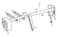
図2において、11は車体構造部品であるステアリングハンガービームを示し、このステアリングハンガービーム11は、ステアリングメンバなどとも呼ばれるもので、車体の図示しないインストルメントパネル部の内部に、車幅方向に沿って配置されている。
In FIG. 2,
そして、このステアリングハンガービーム11は、長尺状のビーム本体15と、このビーム本体15の両端部に設けられるサイドブラケット16,16と、このビーム本体15から下方に向けて突出する支持ブラケット17,17と、ビーム本体15から後方に向けて突出するステアリング支持部18,18とを備えている。なお、本実施の形態のステアリングハンガービーム11としては、運転席が車体の左側に位置する、いわゆる左ハンドル用のものを図示するが、左右反転して構成することで右ハンドル用のものにも対応できる。また、以下、上下方向や左右方向などの方向については、車両の直進状態を基準とする。
The
ビーム本体15は、メインパイプなどとも呼ばれるもので、略円筒状に形成されている。このビーム本体15は、長手方向(軸方向)の一端側に位置する鋳ぐるみ部材としての第1本体部(一端側本体部)21と、長手方向(軸方向)の他端側に位置する被接続部としての第2本体部(他端側本体部)22とが例えば溶接により同軸状に接続されて構成されている。
The
第1本体部21は、インサート部材としてのパイプ部(筒体)25と、鋳物部(ブラケット部材)26とが一体的に成形されて略円筒状に設けられている。
The
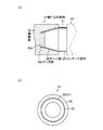
パイプ部25は、金属材料、本実施の形態では鋼鉄により円筒状(図1(b))に成形されている。このパイプ部25は、図1(a)に示すように、円筒状のインサート部材本体としてのパイプ部本体31と、このパイプ部本体31と連続するテーパ部32とを一体に備えている。
The
パイプ部本体31は、パイプ部25の他端側を構成するもので、直管状に形成され、両端部間が貫通している。すなわち、このパイプ部本体31は、径寸法が略一定に設定されている。このパイプ部本体31は、第1本体部21と第2本体部22とを連結する連結部となっている。また、このパイプ部本体31は、鋳物部26に覆われておらず露出している。さらに、このパイプ部本体31の一端側には、テーパ部32が連続している。また、このパイプ部本体31の他端側は、第2本体部22の一端部に例えば溶接などにより連結されている。
The
テーパ部32は、パイプ部25の一端側を構成するもので、パイプ部本体31側である基端側からその反対側である先端側(鋳物部26側)に向かって徐々に縮小、本実施の形態では縮径するように形成されている(縮管されている)。このテーパ部32は、本実施の形態において、基端部から先端部まで略一定の傾斜となるように形成されている。すなわち、このテーパ部32は、截頭円錐筒形状となっている。また、このテーパ部32は、鋳物部26にインサートされるインサート部であり、少なくとも外側が鋳物部26により覆われていて外部に露出していない。
The
一方、鋳物部26は、パイプ部25を構成する金属材料とは異なる金属材料、本実施の形態では軽金属材料であるマグネシウムにより円筒状に成形されている。この鋳物部26は、パイプ部25(パイプ部本体31)よりも外径寸法が大きい円筒状に形成されている。また、この鋳物部26は、パイプ部25の一端部の内部に一部が入り込んで形成されている。換言すれば、鋳物部26は、パイプ部25の内部に位置する突出部26aを備えている。したがって、この突出部26aは、パイプ部25のテーパ部32の内面に沿って、パイプ部25(テーパ部32)内方すなわち他端側に向かって徐々に拡大(拡径)されるように形成されている。このため、パイプ部25のテーパ部32の先端部は、鋳物部26に対して埋め込まれて内面及び外面がそれぞれ鋳物部26により覆われるアンカ部32aとなっている。
On the other hand, the
図2に戻って、第2本体部22は、例えば鋼鉄、すなわちパイプ部25と同一の金属材料により鋳造されて略円筒状に設けられている。
Returning to FIG. 2, the second
サイドブラケット16,16は、ステアリングハンガービーム11を車体の図示しないフロントピラー間に固定するものである。なお、これらサイドブラケット16,16は、本実施の形態では、例えば一方が第1本体部21(鋳物部26)と一体に成形され、他方が第2本体部22と一体に成形されている。なお。これらサイドブラケット16,16は、ビーム本体15と別体で成形されて溶接などによりで一体化されてもよい。
The
各支持ブラケット17は、ステアリングハンガービーム11を車体フロアなどに固定するものである。例えば本実施の形態では、一の支持ブラケット17がビーム本体15の長手方向の中央部にて第2本体部22に突設され、他の支持ブラケット17がサイドブラケット16の近傍にて第2本体部22に突設されている。したがって、各支持ブラケット17は、第2本体部22と同一の金属材料により形成されている。なお、これら支持ブラケット17は、ビーム本体15(第2本体部22)と予め一体に成形されてもよいし、ビーム本体15(第2本体部22)と同一または異なる金属材料により別体で成形されて溶接などにより一体化されてもよい。
Each
ステアリング支持部18,18は、運転席に配置されるハンドルであるステアリングホイール及びこのステアリングホイールに接続される操縦装置であるステアリングシャフト(ステアリングコラムシャフト)などを含むステアリング装置と図示しない車体側部材との間に亘って位置し、ステアリング装置を支持して車体側部材に固定するものである。これらステアリング支持部18,18は、例えばビーム本体15の第1本体部21(鋳物部26)に互いに離間されて突設されている。したがって、これらステアリング支持部18,18は、鋳物部26と同一の金属材料により形成されている。なお、これらステアリング支持部18,18は、ビーム本体15(第1本体部21(鋳物部26))と予め一体に成形されてもよいし、ビーム本体15(第1本体部21(鋳物部26))と同一または異なる金属材料により別体で成形されて溶接などにより一体化されてもよい。
The steering supports 18, 18 are a steering device including a steering wheel as a steering wheel disposed in the driver's seat, a steering shaft (steering column shaft) as a steering device connected to the steering wheel, and a vehicle body side member (not shown). Is located between the two and supports the steering device and is fixed to the vehicle body side member. The
次に、上記の第1の実施の形態の製造方法を説明する。 Next, the manufacturing method of said 1st Embodiment is demonstrated.
ステアリングハンガービーム11は、概略として、第1本体部21と第2本体部22とを別個に成形し、第1本体部21のパイプ部25の端部を第2本体部22の端部と溶接などにより連結して製造される。
In general, the steering
第1本体部21を成形する際には、まず、予め筒状のパイプ部25の一端側を、先端側に向かって縮小するテーパ部32として形成する(形成工程)。
When the first
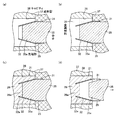
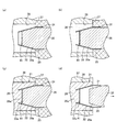
次いで、図3(a)に示す中子35を用い、このパイプ部25の他端部、すなわちパイプ部本体31側から中子35を挿入する(挿入工程)。この中子35は、溶融した金属材料36(図3(b))がパイプ部25の内部に所定以上入り込まないようにする、換言すれば、鋳物部26(図1(a))のパイプ部25の内部での形状を設定するものである。この中子35は、耐熱性を有する金属などの材料により、パイプ部25の内面に嵌合する形状、すなわち先端部35aがテーパ部32の内面に沿って基端側から先端側へと徐々に縮小(縮径)される柱状(円柱状)に形成されている。そして、この中子35は、パイプ部25に挿入した状態で、この先端部35aがパイプ部25(テーパ部32)の先端部に対して基端側に離間した位置とする。
Next, using the
さらに、成形型37,37を用い、中子35を挿入したパイプ部25のテーパ部32のみを、成形型37,37間のキャビティ38にインサートする(インサート工程)。
Further, only the
この状態で、図3(b)に示すように、キャビティ38に、パイプ部25を構成する金属材料と異なり鋳物部26(図1(a))を構成するための溶融した金属材料(マグネシウム)36を充填する(充填工程)。このとき、金属材料36は、パイプ部25の外面とキャビティ38との間に流れ込むとともに、中子35の先端部35aがパイプ部25の先端部から他端側に離間されるように位置していることにより、一部がパイプ部25の先端部からテーパ部32の内部に流れ込み、中子35の先端部35aと接触した状態となる。
In this state, as shown in FIG. 3 (b), the molten metal material (magnesium) for forming the casting portion 26 (FIG. 1 (a)) is formed in the
そして、この金属材料36を冷却することにより凝固させて、図3(c)に示すように、パイプ部25のテーパ部32を鋳ぐるんで鋳物部26を形成する(凝固工程)。このとき、パイプ部25のテーパ部32の先端側に入り込んだ金属材料36(図3(b))が冷却されることで、鋳物部26の一部が、テーパ部32の内面を覆う突出部26aとなり、テーパ部32の先端部が鋳物部26に埋め込まれたアンカ部32aとして形成される。また、パイプ部25のテーパ部32は、金属材料36(図3(b))の凝固収縮に伴い若干の径方向(中心軸に向かう方向)への縮小(縮管)が生じる。
Then, the
この後、成形型37,37を開き、図3(d)に示すように中子35をパイプ部25の他端部(パイプ部本体31)から引き抜く(引き抜き工程)。このとき、本実施の形態によれば、パイプ部25の一端側に、先端側に向かって徐々に縮小するテーパ部32を形成していることにより、このパイプ部25の他端部から中子35を挿入した状態でこのパイプ部25のテーパ部32をインサートした成形型37,37のキャビティ38に金属材料36(図3(b))を充填してテーパ部32を鋳ぐるむ鋳物部26を形成することで、中子35の挿入方向に対して反対方向に徐々に拡大するテーパ部32によって、鋳物部26を鋳込む際にパイプ部25に挿入された中子35に対する、鋳物部26の成形収縮に起因するパイプ部25の縮小による中子35への食い付きを抑制でき、鋳物部26の成形後に中子35をパイプ部25から容易に引き抜くことができる。したがって、第1本体部21を成形型37,37から容易に取り外すことができる。
Thereafter, the
また、鋳物部26を形成する際に、中子35の先端部35aをパイプ部25の一端部に対して他端側に位置するように挿入した状態とすることにより、テーパ部32の先端部に金属材料36(図3(b))を流し込ませて、テーパ部32の先端部を、鋳物部26に埋め込むアンカ部32aとすることができ、鋳物部26のテーパ部32内に入り込んだ突出部26aが抜け方向に対してテーパ部32の先端側に引っ掛かるように位置し、鋳物部26に対するパイプ部25の抜け強度を向上できる。
Further, when forming the casting
そして、成形型37,37及び中子35は、シンプルな構造とすることができ、容易なインサート鋳造が可能となる。
The
次に、第2の実施の形態を図4及び図5を参照して説明する。なお、上記の第1の実施の形態と同様の構成及び作用については、同一符号を付してその説明を省略する。 Next, a second embodiment will be described with reference to FIGS. In addition, about the structure and effect | action similar to said 1st Embodiment, the same code | symbol is attached | subjected and the description is abbreviate | omitted.
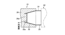
本実施の形態は、上記の第1の実施の形態の第1本体部21のパイプ部25が、図4に示すように内蓋部41を備えるものである。
In the present embodiment, the
この内蓋部41は、テーパ部32の内部に配置されており、このテーパ部32を閉塞して、すなわちこのテーパ部32(パイプ部25)の軸方向に対して交差(直交)する方向に沿って形成されている。したがって、この内蓋部41は、テーパ部32(パイプ部25)を横切って形成されている。このため、パイプ部25は、両端部間が貫通しないように形成されている。本実施の形態において、この内蓋部41は、テーパ部32の長手方向(軸方向)の両端間で、テーパ部32の先端側寄りに位置している。すなわち、この内蓋部41は、テーパ部32の基端部及び先端部からそれぞれ離間された位置に配置されている。この内蓋部41は、パイプ部25と一体に成形されていてもよいし、このパイプ部25と別体で成形されて溶接などにより一体化されていてもよい。
The
そして、この第1本体部21を製造する際には、上記の第1の実施の形態と同様に、まず、予め筒状のパイプ部25の一端側を、先端側に向かって縮小するテーパ部32として形成するとともにこのテーパ部32の内部に内蓋部41を形成し(形成工程)、このパイプ部25の他端部、すなわちパイプ部本体31側から、図5(a)に示す中子35を挿入する(挿入工程)。この中子35は、先端部35aを内蓋部41に当接させた位置とする。
When the first
次いで、成形型37,37を用い、中子35を挿入したパイプ部25のテーパ部32のみを、成形型37,37間のキャビティ38にインサートする(インサート工程)。
Next, only the
この状態で、図5(b)に示すように、キャビティ38に、パイプ部25を構成する金属材料と異なり鋳物部26(図4)を構成するための溶融した金属材料(マグネシウム)36を充填する(充填工程)。このとき、金属材料36は、一部がパイプ部25の先端部からテーパ部32の内部に流れ込み、内蓋部41と接触した状態となる。
In this state, as shown in FIG. 5 (b), the
そして、この金属材料36を冷却することにより凝固させて、図5(c)に示すように、パイプ部25のテーパ部32を鋳ぐるんで鋳物部26を形成する(凝固工程)。このとき、パイプ部25のテーパ部32の先端側に入り込んだ金属材料36(図5(b))が冷却されることで、鋳物部26の一部が、テーパ部32の内面を覆い内蓋部41と接触する突出部26aとなり、テーパ部32の先端部が鋳物部26に埋め込まれたアンカ部32aとして形成される。
Then, the
この後、成形型37,37を開き、図5(d)に示すように中子35をパイプ部25の他端部(パイプ部本体31)から引き抜く(引き抜き工程)。
Thereafter, the
このとき、パイプ部25の鋳物部26により鋳ぐるまれる一端側に、先端側に向かって徐々に縮小するテーパ部32を形成し、また、テーパ部32の先端部を、鋳物部26に埋め込むアンカ部32aとするなど、上記の第1の実施の形態と同様の構成を有することにより、上記の第1の実施の形態と同様の作用効果を奏することができる。
At this time, a tapered
また、パイプ部25にテーパ部32の内部を閉塞する内蓋部41を設けることにより、パイプ部25のテーパ部32での縮小(縮管)に対する剛性を向上できるので、鋳物部26の成形収縮に起因するパイプ部25の縮小による中子35に対する食い付きをより確実に抑制できる。
In addition, by providing the
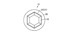
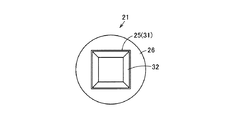
なお、上記の各実施の形態において、例えば図6に示す第3の実施の形態のように、パイプ部25は、六角筒状としてもよいし、図7に示す第4の実施の形態のように、四角筒状としてもよい。すなわち、パイプ部25の断面形状は、任意の多角形状とすることもできる。
In each of the above embodiments, for example, as in the third embodiment shown in FIG. 6, the
また、中子35は、成形型37と一体に形成することもできる。
Further, the core 35 can be formed integrally with the
さらに、上記の各実施の形態の構成は、車体構造部品(ステアリングハンガービーム11)だけでなく、その他の任意の鋳ぐるみ部材に適用できる。 Furthermore, the configuration of each of the above embodiments can be applied not only to the vehicle body structural component (the steering hanger beam 11) but also to any other cast-in member.
本発明は、例えばステアリングハンガービームの少なくとも一部に好適に用いることができる。 The present invention can be suitably used for at least a part of a steering hanger beam, for example.
21 鋳ぐるみ部材としての第1本体部
25 インサート部材としてのパイプ部
26 鋳物部
32 テーパ部
32a アンカ部
35 中子
35a 先端部
36 金属材料
37 成形型
38 キャビティ
41 内蓋部
21 1st body part as cast-in member
25 Pipe section as insert member
26 Casting part
32 Taper
32a Anchor part
35 core
35a Tip
36 Metal materials
37 Mold
38 cavity
41 Inner lid
Claims (6)
このインサート部材の一端側を鋳ぐるむ金属製の鋳物部とを具備し、
前記インサート部材は、前記鋳物部により鋳ぐるまれた一端側に、先端側に向かって徐々に縮小するテーパ部を備えた
ことを特徴とする鋳ぐるみ部材。 A metal insert member formed in a cylindrical shape;
A metal casting part for casting one end of the insert member;
The insert member is provided with a tapered portion that gradually decreases toward the tip end side at one end side that is cast around by the casting portion.
ことを特徴とする請求項1記載の鋳ぐるみ部材。 The cast-in member according to claim 1, wherein the tip of the tapered portion is an anchor portion embedded in the casting portion.
ことを特徴とする請求項1または2記載の鋳ぐるみ部材。 The insert member is provided with an inner lid portion that closes the inside of the tapered portion.
このインサート部材の他端部から中子を挿入した状態でこのインサート部材のテーパ部を成形型のキャビティにインサートし、このキャビティに金属材料を充填して前記テーパ部を鋳ぐるむ鋳物部を形成する
ことを特徴とする鋳ぐるみ部材の製造方法。 One end side of the cylindrical metal insert member is formed as a tapered portion that gradually decreases toward the tip side,
With the core inserted from the other end of the insert member, the taper portion of the insert member is inserted into the cavity of the mold, and the casting portion is formed by filling the cavity with a metal material and casting the taper portion. A method for producing a cast-in member, characterized by:
ことを特徴とする請求項4記載の鋳ぐるみ部材の製造方法。 When forming the cast part, the metal material is poured into the tip part of the taper part by inserting the tip part of the core so as to be positioned on the other end side with respect to one end part of the insert member. The method of manufacturing a cast-in member according to claim 4, wherein the tip of the tapered portion is an anchor portion embedded in the cast portion.
ことを特徴とする請求項4または5記載の鋳ぐるみ部材の製造方法。 The method for manufacturing a cast-in member according to claim 4 or 5, wherein an inner lid portion for closing the inside of the tapered portion is formed on the insert member.
Priority Applications (1)
| Application Number | Priority Date | Filing Date | Title |
|---|---|---|---|
| JP2016084795A JP2017192964A (en) | 2016-04-20 | 2016-04-20 | Cast-in member and method for manufacturing the same |
Applications Claiming Priority (1)
| Application Number | Priority Date | Filing Date | Title |
|---|---|---|---|
| JP2016084795A JP2017192964A (en) | 2016-04-20 | 2016-04-20 | Cast-in member and method for manufacturing the same |
Publications (1)
| Publication Number | Publication Date |
|---|---|
| JP2017192964A true JP2017192964A (en) | 2017-10-26 |
Family
ID=60156165
Family Applications (1)
| Application Number | Title | Priority Date | Filing Date |
|---|---|---|---|
| JP2016084795A Pending JP2017192964A (en) | 2016-04-20 | 2016-04-20 | Cast-in member and method for manufacturing the same |
Country Status (1)
| Country | Link |
|---|---|
| JP (1) | JP2017192964A (en) |
-
2016
- 2016-04-20 JP JP2016084795A patent/JP2017192964A/en active Pending
Similar Documents
| Publication | Publication Date | Title |
|---|---|---|
| EP2698267B1 (en) | Stabilizer link and method for manufacturing same | |
| JP6461654B2 (en) | Manufacturing method of headrest stay | |
| JP5755591B2 (en) | Cast body manufacturing method and manufacturing apparatus | |
| JP6150348B2 (en) | Ball joint bearing seat and ball joint | |
| JP6021769B2 (en) | Subframe for vehicle and method for manufacturing the same | |
| US20060000574A1 (en) | Feeder with a tubular body | |
| JP2017192965A (en) | Insert member and method for manufacturing same | |
| CN104108416B (en) | car steering system | |
| JP2017192964A (en) | Cast-in member and method for manufacturing the same | |
| JP5462523B2 (en) | Integrated structure of metal parts having different material components and manufacturing method thereof | |
| JP2016155159A (en) | Precision casting method and dewaxing auxiliary member | |
| JP5626125B2 (en) | Column unit for electric power steering system | |
| KR102291981B1 (en) | Deformation prevention structure of cowl cross member and its method | |
| JP5607128B2 (en) | Manufacturing method of outer tube and manufacturing method of outer tube with bearing | |
| JP2004330207A (en) | Die structure for casting and method for casting wheel of two-wheel motorcycle using the same | |
| JP4295019B2 (en) | Casting mold for wheels for motorcycles | |
| JP3787936B2 (en) | Steering wheel and steering wheel core mold | |
| JP6330375B2 (en) | Aluminum alloy casting material production equipment | |
| JP2018058429A (en) | Outer column, manufacturing method thereof, and steering column | |
| US12005492B2 (en) | Vehicle support structure and method for manufacturing vehicle support structure | |
| JP2014113967A (en) | Column unit for electrically-driven power steering device | |
| JP2018058429A5 (en) | ||
| JP2025140239A (en) | Instrument panel reinforcement for vehicle | |
| JP4798063B2 (en) | Molding method for two-color molded products. | |
| JP2018058428A5 (en) |
Legal Events
| Date | Code | Title | Description |
|---|---|---|---|
| A621 | Written request for application examination |
Free format text: JAPANESE INTERMEDIATE CODE: A621 Effective date: 20190128 |
|
| A977 | Report on retrieval |
Free format text: JAPANESE INTERMEDIATE CODE: A971007 Effective date: 20191209 |
|
| A131 | Notification of reasons for refusal |
Free format text: JAPANESE INTERMEDIATE CODE: A131 Effective date: 20191211 |
|
| A02 | Decision of refusal |
Free format text: JAPANESE INTERMEDIATE CODE: A02 Effective date: 20200610 |