JP2017193031A - Work tool bag - Google Patents
Work tool bag Download PDFInfo
- Publication number
- JP2017193031A JP2017193031A JP2016085983A JP2016085983A JP2017193031A JP 2017193031 A JP2017193031 A JP 2017193031A JP 2016085983 A JP2016085983 A JP 2016085983A JP 2016085983 A JP2016085983 A JP 2016085983A JP 2017193031 A JP2017193031 A JP 2017193031A
- Authority
- JP
- Japan
- Prior art keywords
- bag
- bag portion
- opening
- tool
- tools
- Prior art date
- Legal status (The legal status is an assumption and is not a legal conclusion. Google has not performed a legal analysis and makes no representation as to the accuracy of the status listed.)
- Pending
Links
- 238000005192 partition Methods 0.000 claims description 13
- 230000009194 climbing Effects 0.000 abstract description 17
- 230000006835 compression Effects 0.000 description 11
- 238000007906 compression Methods 0.000 description 11
- 239000000463 material Substances 0.000 description 11
- 239000000853 adhesive Substances 0.000 description 9
- 230000001070 adhesive effect Effects 0.000 description 9
- 238000009958 sewing Methods 0.000 description 9
- 238000003780 insertion Methods 0.000 description 8
- 230000037431 insertion Effects 0.000 description 8
- 125000000391 vinyl group Chemical group [H]C([*])=C([H])[H] 0.000 description 8
- 229920002554 vinyl polymer Polymers 0.000 description 8
- 239000004744 fabric Substances 0.000 description 7
- 239000010985 leather Substances 0.000 description 7
- 239000002649 leather substitute Substances 0.000 description 7
- 229920003002 synthetic resin Polymers 0.000 description 7
- 239000000057 synthetic resin Substances 0.000 description 7
- 239000000725 suspension Substances 0.000 description 6
- 239000011810 insulating material Substances 0.000 description 5
- 238000000034 method Methods 0.000 description 2
- 230000002093 peripheral effect Effects 0.000 description 1
- 230000001012 protector Effects 0.000 description 1
- 238000004804 winding Methods 0.000 description 1
Images

Landscapes
- Workshop Equipment, Work Benches, Supports, Or Storage Means (AREA)
Abstract
Description
本発明は、作業用工具袋に関し、特に、電柱等における柱上作業に有効な作業用工具袋に関する。 The present invention relates to a work tool bag, and more particularly to a work tool bag effective for work on a pole in a utility pole or the like.
従来、電柱に登って電線ヒューズ等の取り替え等の柱上作業を行う場合、例えば、作業者が地上で工具袋内に作業に必要な部品類(電線ヒューズ、高圧ヒューズ、ヒューズ筒、スリーブ、ビニルテープ、バインド線等)や、工具類(ペンチ、圧縮ペンチ、ドライバー等)を収納し、工具袋の取手にロープを取り付け、工具袋を地上に置いた状態で作業者がロープを持って電柱の所定の高さまで登り、ロープを手繰り寄せて工具袋を引き上げ、工具袋の取手からロープを取り外し、工具袋を取手を介して足場ボルト等に吊り下げ、工具袋から部品類や工具類を出し入れすることにより、各種の柱上作業を行っている。 Conventionally, when working on poles such as replacing electric wire fuses etc. by climbing on a power pole, for example, parts necessary for work in the tool bag on the ground (electric wire fuse, high voltage fuse, fuse cylinder, sleeve, vinyl, etc. Tape, bind wires, etc.) and tools (pliers, compression pliers, screwdrivers, etc.), attach a rope to the handle of the tool bag, and put the rope on the ground with the operator holding the tool bag on the ground. Climb to the specified height, pull the rope up and pull up the tool bag, remove the rope from the handle of the tool bag, hang it on the scaffolding bolt etc. through the handle of the tool bag, and put in and out parts and tools from the tool bag As a result, various column work is performed.
また、作業者が地上で安全ベルトに腰袋を取り付け、腰袋内に上記の部品類や工具類を収納し、作業者が安全ベルトに腰袋を取り付けた状態で電柱の所定の高さまで登り、腰袋から上記の部品類や工具類を直接出し入れすることにより、或いは、安全ベルトから腰袋を取り外して、取手を介して腰袋を足場ボルト等に吊り下げ、腰袋から部品類や工具を出し入れすることにより、各種の柱上作業を行っている。 In addition, the operator attaches a waist bag to the safety belt on the ground, stores the above parts and tools in the waist bag, and the operator climbs up to a predetermined height of the utility pole with the waist bag attached to the safety belt. , Remove the waist bag directly from the waist bag or remove the waist bag from the safety belt and hang the waist bag to the scaffolding bolt etc. via the handle. By taking in and out, various types of work on the pillars are performed.
ところで、電柱の所定の高さまで工具袋をロープで引き上げる方法は、弱電線等の装柱状況によっては、ロープや工具袋が弱電線等に引っ掛かるおそれがあるため、適用可能な作業現場の範囲が制限される。また、ロープで工具袋を引き上げる際に、工具袋が傾いて部品類や工具類が地上に落下するおそれがある。 By the way, the method of pulling the tool bag up to the predetermined height of the utility pole with the rope may cause the rope or the tool bag to be caught by the weak wire etc. Limited. Further, when pulling up the tool bag with a rope, the tool bag may be inclined and parts and tools may fall to the ground.
また、安全ベルトに腰袋を取り付ける方法は、腰袋の容積が小さく、腰袋内に作業に必要な部品類や工具類を一杯に詰めることになるため、作業の際に腰袋から部品類や工具類の出し入れがしづらく、作業効率が悪くなる。また、腰袋から工具類を出し入れする際に、工具同士が引っ掛かって地上に落下するおそれがある。さらに、電柱に登る際の作業者の姿勢によっては、腰袋が傾いて腰袋内から工具類や部品類が地上に落下するおそれがある。 Also, the method of attaching the waist bag to the safety belt is that the volume of the waist bag is small, and the parts and tools necessary for work are packed in the waist bag. It is difficult to put in and take out tools and tools, resulting in poor work efficiency. Moreover, when tools are taken in and out of the waist bag, the tools may be caught and fall to the ground. Furthermore, depending on the posture of the worker when climbing the utility pole, the waist bag may be inclined and tools and parts may fall from the waist bag to the ground.
特許文献1には、上端が開口された収納袋部と、収納袋部の開口縁部に設けられた吊下げベルトと、収納袋部の開口縁部に設けられた留め具部材とを備えた長尺工具用収納袋が記載されている。 Patent Document 1 includes a storage bag portion having an upper end opened, a suspension belt provided at an opening edge portion of the storage bag portion, and a fastener member provided at an opening edge portion of the storage bag portion. A long tool storage bag is described.
特許文献1に記載の長尺工具用収納袋を用いて電柱に登って柱上作業を行うには、収納袋部に部品類や工具類(ホットスティック等)を収納し、収納袋部から突出している工具類の周囲に留め具部材を巻き付けることにより、工具類を留め具部材で束ねた状態とする。 In order to perform work on the pole by climbing the utility pole using the long tool storage bag described in Patent Document 1, parts and tools (hot sticks, etc.) are stored in the storage bag portion and protruded from the storage bag portion. The tool is bundled with the fastener member by winding the fastener member around the tools.
そして、吊下げベルトにロープを取り付けて、作業者がロープを持って電柱の所定の高さまで登り、ロープを手繰り寄せて長尺工具用収納袋を引き上げ、吊下げベルトからロープを取り外して、吊下げベルトを介して長尺工具用収納袋を電柱の足場ボルト等に吊り下げ、長尺工具用収納袋から部品類や工具類を出し入れすることにより、各種の柱上作業を行うことができる。 Then, attach the rope to the suspension belt, and the operator climbs up to the predetermined height of the utility pole by holding the rope, pulls the rope up to pull up the long tool storage bag, removes the rope from the suspension belt, Various work on the pole can be performed by suspending the long tool storage bag on the scaffolding bolt of the electric pole through the lowering belt, and putting parts and tools in and out of the long tool storage bag.
特許文献1に記載の長尺工具用収納袋を用いることにより、ロープで長尺工具用収納袋を引き上げる際に、長尺工具用収納袋が傾いて部品類や工具類が地上に落下するおそれはない。しかし、弱電線等の装柱状況によっては、ロープや長尺工具用収納袋が弱電線等に引っ掛かるおそれがあるため、適用可能な作業現場の範囲が制限されることになる。 By using the long tool storage bag described in Patent Document 1, when the long tool storage bag is pulled up with a rope, the long tool storage bag is tilted and components and tools fall to the ground. It is not. However, depending on the situation of the pillars such as weak wires, the rope and the long tool storage bag may be caught by the weak wires, which limits the range of applicable work sites.
特許文献2には、吊り下げ部と、吊り下げ部の前面に設けられた複数の工具挿入部と、工具挿入部の前方を覆うように、吊り下げ部の側端部に周縁部が固着された袋状部と、吊り下げ部の上端部から後方に延出された延出部とからなる袋本体と、延出部に形成された長孔に対して上下方向にスライド自在に設けられたスライド部材とを備えた工具袋が記載されている。
In
特許文献2に記載の工具袋を用いて電柱に登って柱上作業を行うには、吊下げ部と延出部とスライド部材とによって形成されるコ字形状の囲みに安全帯のベルトを挿入することにより、安全帯に工具袋を取り付ける。
To climb the pole and perform work on the pole using the tool bag described in
そして、袋本体の袋状部及び工具挿入部に部品類や工具類を収納し、作業者が安全ベルトに腰袋を取り付けた状態で電柱の所定の高さまで登り、安全帯のベルトから工具袋を取り外し、工具袋のスライド部材の上端部に設けられた引掛け部材を電柱の足場ボルト等に吊り下げ、袋本体の袋状部及び工具挿入部から部品類や工具を出し入れすることにより、各種の柱上作業を行うことができる。 Then, the parts and tools are stored in the bag-like part and the tool insertion part of the bag body, and the operator climbs up to a predetermined height of the utility pole with the waist bag attached to the safety belt, and the tool bag from the belt of the safety belt. , Hanging the hooking member provided on the upper end of the slide member of the tool bag to the scaffolding bolt etc. of the utility pole, and removing parts and tools from the bag-like part and tool insertion part of the bag body Work on the pillars.
特許文献2に記載の工具袋を用いることにより、袋状部及び工具挿入部内に部品類や工具類を整理して収納することができるので、部品類や工具類の出し入れがし易く、作業効率を高めることができる。また、工具類を出し入れする際に、工具同士が引っ掛かって地上に落下するようなことはない。しかし、電柱に登る際の作業者の姿勢によっては、工具袋が傾いて袋状部及び工具挿入部内から工具類や部品類が地上に落下するおそれがある。
By using the tool bag described in
本発明は、上記のような従来の問題に鑑みなされたものであって、電柱等に登って電線ヒューズ等の取り替え等の各種の柱上作業を行う場合に、弱電線等の装柱状況に影響されることなく、各種の現場に適用することができるとともに、電柱に登る際の作業者の姿勢によって内部から工具類や部品類が地上に落下するおそれがなく、さらに、出し入れがし易く、作業効率を高めることができる作業用工具袋を提供することを目的とする。 The present invention has been made in view of the above-described conventional problems, and when performing various types of work on poles such as replacement of electric wire fuses etc. by climbing on electric poles, etc. It can be applied to various sites without being affected, and there is no risk of tools and parts falling from the inside to the ground depending on the posture of the worker when climbing the utility pole, and it is easy to take in and out. An object of the present invention is to provide a working tool bag capable of improving working efficiency.
上記のような課題を解決するために、本発明は、以下のような手段を採用している。
すなわち、本発明は、柱上作業に用いる作業用工具袋であって、上部が開口された第1袋部と、該第1袋部の前面側に設けられる前記第1袋部よりも容積の小さい上部が開口された第2袋部と、該第2袋部の前面側に設けられる前記第2袋部よりも容積の小さい上部が開口された第3袋部とからなる袋本体と、前記第3袋部の開口部を開閉する内蓋と、前記第1袋部の開口部及び前記第2袋部の開口部を開閉するとともに、前記第3袋部の開口部を前記内蓋の外側から二重に開閉する外蓋と、前記第1袋部の背面側に設けられる肩掛け用紐と、前記第1袋部の背面側の前記肩掛け用紐よりも下方の部分に設けられる固定用ベルトとを備えていることを特徴とする。
In order to solve the above problems, the present invention employs the following means.
That is, the present invention is a working tool bag used for work on a pillar, and has a first bag portion having an upper opening, and a volume larger than that of the first bag portion provided on the front side of the first bag portion. A bag main body comprising a second bag portion having a small upper portion opened, and a third bag portion having an upper portion having a smaller volume than the second bag portion provided on the front side of the second bag portion; An inner lid that opens and closes the opening of the third bag portion, and opens and closes the opening of the first bag portion and the opening of the second bag portion, and the opening of the third bag portion is located outside the inner lid. An outer lid that double opens and closes, a shoulder strap provided on the back side of the first bag portion, and a fixing belt provided in a portion below the shoulder strap on the back side of the first bag portion. It is characterized by having.
本発明の作業用工具袋によれば、例えば、電柱に登って電線ヒューズの取り替え等の柱上作業を行う場合に、第1袋部に電線ヒューズ等の部品類、及び圧縮ペンチ等の工具類を収納し、第2袋部にドライバー、カッターナイフ等の工具類を収納し、第3袋部内にスリーブ、ビニルテープ、バインド線等の部品類を収納し、第3袋部の開口部を内蓋で閉塞し、第1袋部及び第3袋部の開口部を外蓋で閉塞し、第3袋部の開口部を内蓋の外側から外蓋で二重に閉塞し、この状態で肩掛け用紐を肩に斜に掛け、固定用ベルトを胴に締め付けることにより、作業用工具袋を腰に固定することができる。そして、この状態で電柱を所定の高さまで登って電線ヒューズの取り替え作業を行うことができる。従って、電柱を登る際の作業者に姿勢によって作業用工具袋が傾いても、第1袋部、第2袋部、及び第3袋部の内部から部品類や工具類が地上に落下するようなことはなく、地上の安全を確保することができる。 According to the working tool bag of the present invention, for example, when climbing the electric pole and performing work on the pole such as replacing the electric wire fuse, parts such as the electric wire fuse and tools such as the compression pliers in the first bag portion The second bag contains tools such as screwdrivers, cutter knives, etc. The third bag contains parts such as sleeves, vinyl tape, and bind wires, and the third bag has an opening inside. Close with the lid, close the opening of the first bag part and the third bag part with the outer lid, and double-close the opening part of the third bag part with the outer lid from the outside of the inner lid. The work tool bag can be fixed to the waist by hooking the strap on the shoulder and fastening the fixing belt to the trunk. In this state, the electric pole can be climbed to a predetermined height, and the electric wire fuse can be replaced. Therefore, even if the working tool bag tilts depending on the posture of the operator when climbing the utility pole, the parts and tools fall from the inside of the first bag part, the second bag part, and the third bag part to the ground. There is nothing that can be done to ensure safety on the ground.
また、第1袋部に電線ヒューズ等の部品類、及び圧縮ペンチ等の工具類を収納し、第2袋部にドライバー、カッターナイフ等の工具類を収納し、第3袋部内にスリーブ、ビニルテープ、バインド線等の部品類を整理して収納することができるので、部品類や工具類の出し入れの際に、部品類同士が引っ掛かったり、工具類同士が引っ掛かって地上に落下するようなことはない。 Also, parts such as electric wire fuses and tools such as compression pliers are stored in the first bag part, tools such as a screwdriver and cutter knife are stored in the second bag part, and a sleeve and vinyl are stored in the third bag part. Since parts such as tapes and bind wires can be stored in an organized manner, when parts and tools are taken in and out, parts may be caught or tools may be caught and fall to the ground. There is no.
さらに、電線ヒューズ等の取り替え作業を行う場合に、肩掛け用紐を電柱の足場ボルト等に引っ掛け、固定用ベルトを電柱の周囲に回して締め付けることにより、作業用袋を電柱に固定することができるので、第1袋部、第2袋部、及び第3袋部からの部品類や工具類の出し入れを容易に行うことができ、電線ヒューズ等の取り替え作業の効率を高めることができる。 Furthermore, when performing a replacement work such as a wire fuse, the working bag can be fixed to the utility pole by hooking the shoulder strap on the scaffolding bolt of the utility pole and tightening the fixing belt around the utility pole. Therefore, the parts and tools from the first bag part, the second bag part, and the third bag part can be easily taken in and out, and the efficiency of replacement work such as electric wire fuses can be improved.
また、本発明において、前記第1袋部の内部には、前記第1袋部の内部を複数の室に区画する仕切りが設けられていることとしてもよい。 In the present invention, a partition that divides the inside of the first bag portion into a plurality of chambers may be provided inside the first bag portion.
本発明の作業用工具袋によれば、第1袋部の内部を、電線ヒューズ等の部品類を収納する室、圧縮ペンチ等の工具類を収納する室、低圧用絶縁ゴム手袋等を収納する室等に区画することができるので、部品類の出し入れや工具類の出し入れの際に、部品同士や工具類同士が引っ掛かるようなことはなく、作業に必要な部品類や工具類の出し入れを容易に、確実に行うことができる。 According to the working tool bag of the present invention, the interior of the first bag portion stores a chamber for storing parts such as an electric wire fuse, a chamber for storing tools such as compression pliers, an insulating rubber glove for low pressure, and the like. Since it can be partitioned into a room, parts and tools do not get caught when putting in and out parts and tools, making it easy to put in and out parts and tools required for work. It can be done reliably.
また、本発明において、前記第3袋部の内部には、前記第3袋部の内部を複数の室に区画する仕切りが設けられていることとしてもよい。 In the present invention, a partition that divides the interior of the third bag portion into a plurality of chambers may be provided inside the third bag portion.
本発明の作業用工具袋によれば、第3袋部の内部を、スリーブ等の部品類を収納する室、ビニルテープ等の部品類を収納する室等に区画することができるので、作業に必要な部品類の出し入れを容易に、確実に行うことができる。 According to the working tool bag of the present invention, the inside of the third bag portion can be partitioned into a chamber for storing parts such as a sleeve, a chamber for storing parts such as vinyl tape, etc. Necessary parts can be taken in and out easily and reliably.
また、本発明において、前記第2袋部の内部には、工具を上方から差し込み可能な工具差しが複数箇所に設けられていることとしてもよい。 Moreover, in this invention, it is good also as the inside of the said 2nd bag part being provided with the tool insertion which can insert a tool from upper direction in multiple places.
本発明の作業用工具袋によれば、所定の工具差しに所定の工具を差し込むように決めておくことにより、作業に必要な工具の出し入れを容易に、確実に行うことができる。 According to the working tool bag of the present invention, it is possible to easily and surely insert and remove a tool necessary for work by determining to insert a predetermined tool into a predetermined tool insertion.
また、本発明において、前記第1袋部は、上部が開口された四角形箱状をなし、前記第2袋部は、上部が開口された四角形箱状をなし、前記第3袋部は、上部が開口された四角形箱状をなしていることとしてもよい。 Further, in the present invention, the first bag portion has a rectangular box shape with an upper portion opened, the second bag portion has a rectangular box shape with an upper portion opened, and the third bag portion has an upper portion. It is good also as having comprised the rectangular box shape by which was opened.
本発明の作業用工具袋によれば、第1袋部、第2袋部、及び第3袋部からの部品類及び工具類の出し入れを容易に、確実に行うことができる。 According to the working tool bag of the present invention, it is possible to easily and reliably put in and out components and tools from the first bag portion, the second bag portion, and the third bag portion.
また、本発明において、前記肩掛け用紐及び前記固定用ベルトは、長さの調節が可能に構成されていることとしてもよい。 In the present invention, the shoulder strap and the fixing belt may be configured to be adjustable in length.
本発明の作業用工具袋によれば、肩掛け用紐の長さ及び固定用ベルトの長さを調節することにより、体格の異なる様々な作業者に対応することができる。 According to the working tool bag of the present invention, it is possible to cope with various workers having different physiques by adjusting the length of the shoulder strap and the length of the fixing belt.
以上、説明したように、本発明の作業用工具袋によれば、電柱等に登って電線ヒューズ等の取り替え等の各種の柱上作業を行う場合に、弱電線等の装柱状況に影響されることなく、各種の現場に対応することができる。また、電柱等に登る際の作業者の姿勢によって内部から工具類や部品類が地上に落下するおそれがない。さらに、出し入れがし易く、作業効率を高めることができる。 As described above, according to the working tool bag of the present invention, when performing various work on poles such as replacement of electric wire fuses etc. by climbing on electric poles etc., it is affected by the situation of poles such as weak wires. It can cope with various sites without having to. Moreover, there is no possibility that tools and parts fall from the inside to the ground depending on the posture of the worker when climbing on the utility pole. Furthermore, it is easy to take in and out, and work efficiency can be improved.
以下、図面を参照しながら本発明の実施の形態について説明する。
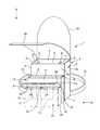
図1〜図3には、本発明の作業用工具袋の一実施の形態が示されている。
本実施の形態の作業用工具袋1は、電柱等に登って各種の柱上作業を行う場合に適用されるものであって、例えば、作業者が電柱に登って電線ヒューズを取り替える柱上作業に有効なものである。
Hereinafter, embodiments of the present invention will be described with reference to the drawings.
1 to 3 show an embodiment of a working tool bag according to the present invention.
The working tool bag 1 according to the present embodiment is applied when various types of work on a pole are performed by climbing on a power pole or the like. For example, a work on a pole in which an operator climbs a power pole and replaces a wire fuse. It is effective for.
作業用工具袋1は、上部が開口された四角箱状の第1袋部3と、第1袋部3の前面3a側に一体に設けられる上部が開口された四角箱状の第2袋部12と、第2袋部12の前面12a側に一体に設けられる上部が開口された四角箱状の第3袋部18と、第3袋部18の開口部を開閉する内蓋26と、第1袋部3、第2袋部12、及び第3袋部18の開口部を開閉する外蓋28とからなる袋本体2と、第1袋部3の背面3b側の上部に設けられる肩掛け用紐30と、第1袋部3の背面3b側の下部に設けられる固定用ベルト31とから構成されている。
The working tool bag 1 includes a square box-shaped
第1袋部3は、絶縁性を有する材料(布、革、合成革、合成樹脂等)から形成されるものであって、四角板状の前板4と、前板4の後方に間隔をおいて設けられる前板4と同一大きさの四角板状の後板5と、前板4と後板5の両端間にそれぞれ設けられる四角板状の側板6と、前板4、後板5、両側板6の下端に設けられる四角板状の底板7とから構成されている。
The
第1袋部3の内部の前板4と後板5との間には、同一大きさの2枚の四角板状の仕切り板8が底部から所定の高さまで及ぶように、かつ両側板6と平行をなすように設けられ、これらの2枚の仕切り板8によって、第1袋部3の内部が中央の第1室9とその両側の第2室10と第3室11の3室に区画されている。仕切り板8は、前板4と後板5との間に接着剤、縫製等の接合手段によって一体に接合してもよいし、前板4と後板5との間に面ファスナー等の着脱手段によって着脱可能に接合してもよい。
Between the
第1袋部3の第1室9には、例えば、低圧用絶縁ゴム手袋等の絶縁用保護具が収納され、第2室10には、圧縮ペンチ等の工具類が収納され、第3室11には、電線ヒューズ、高圧ヒューズ、ヒューズ筒等の部品類が収納される。
In the
第2袋部12は、絶縁性を有する材料(布、革、合成革、合成樹脂等)から形成されるものであって、第1袋部3の前板4及び後板5と同一幅の四角板状の前板13と、前板13の後方に間隔をおいて設けられる前板13と同一大きさの四角板状の後板14と、前板13と後板14の両端間にそれぞれ設けられる四角板状の側板15と、前板13、後板14、両側板15の下端に設けられる四角板状の底板16とから構成されている。
The
第2袋部12は、底板16が第1袋部3の底板7と面一となり、両側板15が第1袋部3の両側板6と面一となるように、第1袋部3の前面3a側に接着剤、縫製等の接合手段によって一体に接合されている。第2袋部12は、第1袋部3よりも容積が小さくなるように、前板13、後板14、側板15、及び底板16の寸法が設定されている。
The
第2袋部12の後板14の内面側には、中央部とその両側の3箇所に半筒状の工具差し17が上下方向を向くように接着剤、縫製等の接合手段によって一体に接合され、これらの工具差し17にドライバー、カッターナイフ、ペンチ、ラチェットレンチ等の工具類が上方から差し込み可能に構成されている。
The inner surface of the
なお、第2袋部12を、前板13と両側板15と底板16とによって構成し、両側板15と底板16の端部を第1袋部3の前板4に一体に接合するように構成してもよい。
The
第3袋部18は、絶縁性を有する材料(布、革、合成革、合成樹脂等)から形成されるものであって、第1袋部3の前板4及び後板5と同一幅の四角形板状の前板19と、前板19の後方に間隔をおいて設けられる前板19と同一大きさの四角形板状の後板20と、前板19と後板20の両端間にそれぞれ設けられる四角形板状の側板21と、前板19、後板20、両側板21の下端に設けられる四角形板状の底板22とから構成されている。
The
第3袋部18は、底板22が第2袋部12の底板16と面一となり、両側板21が第2袋部12の両側板15と面一となるように、第2袋部12の前面12aに接着剤、縫製等の接合手段によって一体に接合されている。第3袋部18は、第2袋部12よりも容積が小さくなるように、前板19、後板20、側板21、及び底板22の寸法が設定されている。
The
第3袋部18の前板19と後板20との間の中央部には、1枚の四角板状の仕切り板23が全高に亘るように、かつ両側板21と平行をなすように設けられ、この1枚の仕切り板23によって第3袋部18の内部が第1室24と第2室25の2室に区画されている。仕切り板23は、前板19と後板20との間に接着剤、縫製等の接合手段によって一体に接合してもよいし、前板19と後板20との間に面ファスナー等の着脱手段によって着脱可能に接合してもよい。
In the central portion between the
第3袋部18の第1室24及び第2室25内には、スリーブ、ビニルテープ、バインド線等の資材類が収納される。
In the
なお、第3袋部18を、前板19と両側板21と底板22とによって構成して、両側板21と底板22の端部を第2袋部12の前板13に一体に接合するように構成してもよい。
The
内蓋26は、絶縁性を有するとともに、弾性変形可能な材料(布、革、合成革、合成樹脂等)から形成される四角板状をなすものであって、第3袋部18の開口部を閉塞可能な寸法に設定されている。内蓋26は、長さ方向の一端が第3袋部18の第2袋部12側の開口縁部に接着剤、縫製等の接合手段によって一体に接合され、長さ方向の他端が第3袋部18の前面18a側の上部に面ファスナー等の着脱手段(図示せず)によって着脱可能に接合されている。
The
外蓋28は、絶縁性を有するとともに、弾性変形可能な材料(布、革、合成革、合成樹脂等)から形成される四角板状をなすものであって、第1袋部3、第2袋部12、及び第3袋部18の開口部を閉塞可能な寸法に設定されている。
The
外蓋28は、長さ方向の一端が第1袋部3の背面3b側の開口縁部に接着剤、縫製等の接合手段によって一体に接合され、長さ方向の他端が第3袋部18の前面18a側の上部(内蓋26の他端よりも下側の部分)に面ファスナー等の着脱手段(図示せず)によって着脱可能に接合されている。
なお、外蓋28を開いた際に、外蓋28の長さ方向の他端を第1袋部3の背面3b側に面ファスナー等の着脱手段(図示せず)によって着脱可能に接合するように構成してもよい。
One end in the length direction of the
When the
肩掛け用紐30は、絶縁性を有する材料(布、革、合成革、合成樹脂等)から形成される紐状をなすものであって、両端が第1袋部3の背面3b側の上部に接着剤、縫製等の接合手段によって一体に接合されている。肩掛け用紐30は、長さの調節が可能に構成されている。
The
固定用ベルト31は、絶縁性を有する材料(布、革、合成革、合成樹脂等)から形成されるベルト状をなすものであって、両端が第1袋部3の背面3b側の下部に接着剤、縫製等の接合手段によって一体に接合されている。固定用ベルト31は、締付け具(図示せず)により締め付け可能に構成されるとともに、長さの調節が可能に構成されている。
The fixing
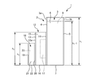
なお、本実施の形態においては、第1袋部3の全高h1を350mm、幅b1を200mm、奥行c1を100mmに設定し、第1室9の幅b1−1を140mm、第2室10の幅b1−2を30mm、第3室11の幅b1−3を30mm、仕切り8の高さh1−1を200mmに設定している。また、第2袋部12の高さh2を150mm、幅b2を200mm、奥行c2を30mmに設定し、第3袋部18の高さh3を100mm、幅b3を200mm、奥行c3を20mmに設定し,第1室24の幅b3−1を100mm、第2室25の幅b3−2を100mmに設定している。
In the present embodiment, the total height h1 of the
上記のように構成した本実施の形態による作業用工具袋1を用いて、電線ヒューズの取り替え作業を行うには、まず、地上において、外蓋28及び内蓋26を開いた状態として、第1袋部3の第1室9内に低圧用絶縁ゴム手袋を収納し、第2室10内に電線ヒューズ等の部品類を収納し、第3室11内に圧縮ペンチ等の工具類を収納する。また、第2袋部12の工具差し17にドライバー、カッターナイフ、ラチェットレンチ等の工具類を差し込み、第3袋部18の第1室24内にスリーブ等の資材類を収納し、第2室25内にビニルテープ、バインド線等の資材類を収納する。
In order to perform a wire fuse replacement operation using the work tool bag 1 according to the present embodiment configured as described above, first, the
次に、内蓋26を閉じて第3袋部18の開口部を閉塞し、外蓋28を閉じて第1袋部3、第2袋部12の開口部を閉塞するとともに、第3袋部18の開口部を内蓋26の外側から二重に閉塞する。
Next, the
次に、肩掛け用紐30を肩に斜に掛け、固定用ベルト31を胴に回して締め付けることにより、作業用工具袋1を腰に固定する。
Next, the work strap 1 is fixed to the waist by hooking the
次に、電柱を所定の高さまで登って、胴から固定用ベルト31を取り外し、肩から肩掛け用紐30を取り外し、肩掛け用紐30を電柱の足場ボルトに引っ掛け、固定用ベルト31を電柱の周囲に回して締め付けることにより、作業用工具袋1を電柱に固定する。
Next, the utility pole is climbed to a predetermined height, the fixing
そして、外蓋28及び内蓋26を開いて、作業に必要な低圧用絶縁ゴム手袋を第1袋部3から取り出して手に装着し、電線ヒューズを第1袋部3から取り出し、電線ヒューズ3の取り替えに必要な工具類(圧縮ペンチ、カッターナイフ、ビニルテープ等)を第1袋部3、第2袋部12、及び第3袋部18から出し入れして、電線ヒューズの取り替え作業を行う。
Then, the
そして、電線ヒューズの取り替え作業の完了後に、取り外した電線ヒューズを第1袋部3内に回収し、内蓋26及び外蓋28を閉じた状態として、第1袋部3、第2袋部12、及び第3袋部18の開口部を閉塞する。
After the wire fuse replacement operation is completed, the removed wire fuse is collected in the
そして、固定用ベルト31を電柱から取り外し、肩掛け用紐30を電柱の足場ボルトから取り外し、肩掛け用紐30を肩に斜に掛け、固定用ベルト31を胴に回して締め付けることにより、作業用工具袋1を腰に固定し、この状態で電柱から地上に降りて、取り替えた電線ヒューズ、圧縮ペンチ等の工具類、ビニルテープ等の資材類を回収することにより、電線ヒューズの取り替え作業が完了することになる。
Then, the fixing
上記のように構成した本実施の形態の作業用工具袋1にあっては、電柱に登って電線ヒューズの取り替え作業を行う場合に、作業用工具袋1の第3袋部18の開口部を内蓋26によって閉塞し、第1袋部3及び第2袋部12の開口部を外蓋28によって閉塞し、第3袋部18の開口部を内蓋26の外側から外蓋28によって二重に閉塞するとともに、肩掛け用紐30を肩に斜に掛け、固定用ベルト31を胴に締め付けることにより、作業用工具袋1を腰に固定しているので、電柱を登る際の作業者の姿勢によって作業用工具袋1が傾いても、第1袋部3の内部から電線ヒューズ等の部品類や圧縮ペンチ等の工具類が、第2袋部12の内部からドライバー、カッターナイフ等の工具類が、第3袋部18の内部からスリーブ等の資材類がそれぞれ地上に落下するようなことはなく、電柱を登る際の安全を確保することができる。
In the working tool bag 1 of the present embodiment configured as described above, when the electric fuse is replaced by climbing on the utility pole, the opening of the
また、電柱の所定の高さまで登って電線ユーズの取り替え作業を行う場合に、電柱の足場ボルトに肩掛け用紐30を引っ掛け、電柱の周囲に固定用ベルト31を回して締め付けることにより、作業用工具袋1を電柱に固定しているので、取り替え作業中の作業者の姿勢によって作業用工具袋1が傾くようなことはない。従って、作業者が第1袋部3から電線ヒューズ等の部品類や圧縮ペンチ等の工具類を出し入し、第2袋部12からドライバー、カッターナイフ等の工具類の出し入れし、第3袋部18からスリーブ等の資材類の出し入れする際に、それらが地上に落下するおそれはなく、電線ヒューズの取り替え作業中の安全を確保することができる。
In addition, when the electric wire use is replaced by climbing to a predetermined height of the electric pole, the work tool is obtained by hooking the
また、電線ヒューズ等の部品類、及び圧縮ペンチ等の工具類を第1袋部3の所定の位置に、ドライバー、カッターナイフ等の工具類を第2袋部12の所定の位置に、スリーブ等の資材類を第3袋部18の所定の位置にそれぞれ整理して収納しているので、部品類や工具類や資材類を出し入れする際に、部品類同士、工具類同士、資材類同士が引っ掛かって地上に落下するようなことはない。また、部品類、工具類、資材類を第1袋部3、第2袋部12、及び第3袋部18から容易に、効率良く出し入れすることができるので、電線ヒューズの取り替え作業を効率良く行うことができる。
Also, parts such as electric wire fuses and tools such as compression pliers are placed at predetermined positions of the
また、内蓋26を面ファスナー等の着脱手段27によって第3袋部18の前面18a側に着脱可能に接合させ、外蓋28を面ファスナー等の着脱手段29によって第3袋部18の前面18a側に着脱可能に接合させているので、第3袋部18、第1袋部3、及び第2袋部12の開口部の開閉を容易に行うことができる。
Further, the
また、弱電線等の装柱状況に影響されることなく、電柱の所定の高さまで登って所定の柱上作業を行うことができるので、適用可能な作業現場の範囲を広げることができる。 In addition, since it is possible to perform work on a predetermined pole by climbing to a predetermined height of the electric pole without being affected by the situation of poles such as weak wires, the range of applicable work sites can be expanded.
なお、前記の説明においては、袋本体2を第1袋部3と第2袋部12と第3袋部18の3つの袋部によって構成したが、袋本体2を2つの袋部又は4つ以上の袋部によって構成してもよい。
In the above description, the
また、前記の説明においては、電線ヒューズの取り替え作業に本発明の作業用工具袋1を用いた場合について説明したが、他の柱上作業に本発明の作業用工具袋1を適用してもよい。
また、電柱の柱上作業に限らず、他の高所での作業に本発明の作業用工具袋1を適用してもよい。
Further, in the above description, the case where the work tool bag 1 of the present invention is used for the work of replacing the electric wire fuse has been described. However, even if the work tool bag 1 of the present invention is applied to other pole work, Good.
Moreover, you may apply the work tool bag 1 of this invention not only to the work on the pole of an electric pole but to the work in other high places.
1 作業用工具袋
2 袋本体
3 第1袋部
4 前板
5 後板
6 側板
7 底板
8 仕切り板
9 第1室
10 第2室
11 第3室
12 第2袋部
13 前板
14 後板
15 側板
16 底板
17 工具差し
18 第3袋部
19 前板
20 後板
21 側板
22 底板
23 仕切り板
24 第1室
25 第2室
26 内蓋
28 外蓋
30 肩掛け用紐
31 固定用ベルト
DESCRIPTION OF SYMBOLS 1
Claims (6)
上部が開口された第1袋部と、該第1袋部の前面側に設けられる前記第1袋部よりも容積の小さい上部が開口された第2袋部と、該第2袋部の前面側に設けられる前記第2袋部よりも容積の小さい上部が開口された第3袋部とからなる袋本体と、前記第3袋部の開口部を開閉する内蓋と、前記第1袋部の開口部及び前記第2袋部の開口部を開閉するとともに、前記第3袋部の開口部を前記内蓋の外側から二重に開閉する外蓋と、前記第1袋部の背面側に設けられる肩掛け用紐と、前記第1袋部の背面側の前記肩掛け用紐よりも下方の部分に設けられる固定用ベルトとを備えていることを特徴とする作業用工具袋。 A working tool bag used for work on a pillar,
A first bag portion having an upper opening; a second bag portion having an upper opening smaller in volume than the first bag portion provided on the front side of the first bag portion; and a front surface of the second bag portion. A bag main body comprising a third bag portion having an upper opening that is smaller in volume than the second bag portion provided on the side; an inner lid that opens and closes the opening portion of the third bag portion; and the first bag portion. An opening for opening and closing the opening of the second bag portion and an opening for opening and closing the opening of the third bag portion from the outside of the inner lid, and a back side of the first bag portion. A working tool bag, comprising: a shoulder strap provided; and a fixing belt provided at a lower portion of the back side of the first bag portion than the shoulder strap.
Priority Applications (1)
| Application Number | Priority Date | Filing Date | Title |
|---|---|---|---|
| JP2016085983A JP2017193031A (en) | 2016-04-22 | 2016-04-22 | Work tool bag |
Applications Claiming Priority (1)
| Application Number | Priority Date | Filing Date | Title |
|---|---|---|---|
| JP2016085983A JP2017193031A (en) | 2016-04-22 | 2016-04-22 | Work tool bag |
Publications (1)
| Publication Number | Publication Date |
|---|---|
| JP2017193031A true JP2017193031A (en) | 2017-10-26 |
Family
ID=60154575
Family Applications (1)
| Application Number | Title | Priority Date | Filing Date |
|---|---|---|---|
| JP2016085983A Pending JP2017193031A (en) | 2016-04-22 | 2016-04-22 | Work tool bag |
Country Status (1)
| Country | Link |
|---|---|
| JP (1) | JP2017193031A (en) |
Cited By (2)
| Publication number | Priority date | Publication date | Assignee | Title |
|---|---|---|---|---|
| CN109291021A (en) * | 2018-11-13 | 2019-02-01 | 国网河南省电力公司漯河供电公司 | A combined appliance box for high-altitude work in electric power construction |
| CN111761561A (en) * | 2020-07-14 | 2020-10-13 | 安徽启源电力设备制造有限公司 | Power maintenance tool placing box structure with self-climbing function and using method thereof |
Citations (6)
| Publication number | Priority date | Publication date | Assignee | Title |
|---|---|---|---|---|
| JPS6036723U (en) * | 1983-08-19 | 1985-03-13 | 株式会社 吉田 | bag |
| JP3032681U (en) * | 1996-06-21 | 1996-12-24 | 株式会社富士 | A bag for carrying a laptop computer, etc. |
| JP3105802U (en) * | 2004-06-09 | 2004-11-25 | 株式会社中林製作所 | Tool holder |
| JP3150392U (en) * | 2009-02-26 | 2009-05-07 | 株式会社中林製作所 | Storage |
| JP3159547U (en) * | 2010-02-15 | 2010-05-27 | 有限会社アイワ・テクノ | Body-mounted tool holder |
| JP3174967U (en) * | 2011-11-14 | 2012-04-19 | 勇一 乾 | Identification type display waist bag |
-
2016
- 2016-04-22 JP JP2016085983A patent/JP2017193031A/en active Pending
Patent Citations (6)
| Publication number | Priority date | Publication date | Assignee | Title |
|---|---|---|---|---|
| JPS6036723U (en) * | 1983-08-19 | 1985-03-13 | 株式会社 吉田 | bag |
| JP3032681U (en) * | 1996-06-21 | 1996-12-24 | 株式会社富士 | A bag for carrying a laptop computer, etc. |
| JP3105802U (en) * | 2004-06-09 | 2004-11-25 | 株式会社中林製作所 | Tool holder |
| JP3150392U (en) * | 2009-02-26 | 2009-05-07 | 株式会社中林製作所 | Storage |
| JP3159547U (en) * | 2010-02-15 | 2010-05-27 | 有限会社アイワ・テクノ | Body-mounted tool holder |
| JP3174967U (en) * | 2011-11-14 | 2012-04-19 | 勇一 乾 | Identification type display waist bag |
Cited By (2)
| Publication number | Priority date | Publication date | Assignee | Title |
|---|---|---|---|---|
| CN109291021A (en) * | 2018-11-13 | 2019-02-01 | 国网河南省电力公司漯河供电公司 | A combined appliance box for high-altitude work in electric power construction |
| CN111761561A (en) * | 2020-07-14 | 2020-10-13 | 安徽启源电力设备制造有限公司 | Power maintenance tool placing box structure with self-climbing function and using method thereof |
Similar Documents
| Publication | Publication Date | Title |
|---|---|---|
| US6267277B1 (en) | Magnetic tool and equipment holder | |
| US9038869B2 (en) | Double tool pouch with retractor pockets | |
| US9968180B2 (en) | Drop prevention apparatus and system for hand tools | |
| AU2019282801B2 (en) | Securing device for tool | |
| US9629446B2 (en) | Tool pouch with retractors | |
| JP2017193031A (en) | Work tool bag | |
| US8091701B1 (en) | Magnetic brush protector and storage apparatus | |
| US9248565B1 (en) | Method and apparatus for securing a tape measure | |
| US9597789B2 (en) | Flexible tool holder | |
| KR20140004694U (en) | Bag for protecting a fruit | |
| CN204209664U (en) | A handy toolbox | |
| JP2011104734A (en) | Tool container | |
| US20090152149A1 (en) | Tool and equipment organizer | |
| JP2014194950A (en) | Battery device for power tool | |
| WO2021020508A1 (en) | Spare blade case | |
| US20140183232A1 (en) | Tool holder | |
| CN205497422U (en) | Tool hanging plate | |
| CN203818124U (en) | Waist-worn tool kit | |
| KR101969834B1 (en) | Portable parts box | |
| KR102629246B1 (en) | Tool bag | |
| JP3241833U (en) | Detachable fall prevention cover for electrical bucket and electrical bucket equipped with the same | |
| CN204431133U (en) | A kind of multifunctional wrench of electrical maintenance | |
| CA2783040A1 (en) | Tool holder | |
| KR101853632B1 (en) | Combined Ladder Tool Bag | |
| JP3195040U (en) | Waist bag |
Legal Events
| Date | Code | Title | Description |
|---|---|---|---|
| A621 | Written request for application examination |
Free format text: JAPANESE INTERMEDIATE CODE: A621 Effective date: 20190320 |
|
| A977 | Report on retrieval |
Free format text: JAPANESE INTERMEDIATE CODE: A971007 Effective date: 20200114 |
|
| A131 | Notification of reasons for refusal |
Free format text: JAPANESE INTERMEDIATE CODE: A131 Effective date: 20200121 |
|
| A02 | Decision of refusal |
Free format text: JAPANESE INTERMEDIATE CODE: A02 Effective date: 20200929 |