JP2017193033A - Tool exchanger, and exchanging method - Google Patents
Tool exchanger, and exchanging method Download PDFInfo
- Publication number
- JP2017193033A JP2017193033A JP2016086007A JP2016086007A JP2017193033A JP 2017193033 A JP2017193033 A JP 2017193033A JP 2016086007 A JP2016086007 A JP 2016086007A JP 2016086007 A JP2016086007 A JP 2016086007A JP 2017193033 A JP2017193033 A JP 2017193033A
- Authority
- JP
- Japan
- Prior art keywords
- tool
- holding member
- longitudinal direction
- holding
- change unit
- Prior art date
- Legal status (The legal status is an assumption and is not a legal conclusion. Google has not performed a legal analysis and makes no representation as to the accuracy of the status listed.)
- Granted
Links
Images
Classifications
-
- B—PERFORMING OPERATIONS; TRANSPORTING
- B23—MACHINE TOOLS; METAL-WORKING NOT OTHERWISE PROVIDED FOR
- B23Q—DETAILS, COMPONENTS, OR ACCESSORIES FOR MACHINE TOOLS, e.g. ARRANGEMENTS FOR COPYING OR CONTROLLING; MACHINE TOOLS IN GENERAL CHARACTERISED BY THE CONSTRUCTION OF PARTICULAR DETAILS OR COMPONENTS; COMBINATIONS OR ASSOCIATIONS OF METAL-WORKING MACHINES, NOT DIRECTED TO A PARTICULAR RESULT
- B23Q3/00—Devices holding, supporting, or positioning work or tools, of a kind normally removable from the machine
- B23Q3/155—Arrangements for automatic insertion or removal of tools, e.g. combined with manual handling
- B23Q3/157—Arrangements for automatic insertion or removal of tools, e.g. combined with manual handling of rotary tools
- B23Q3/15706—Arrangements for automatic insertion or removal of tools, e.g. combined with manual handling of rotary tools a single tool being inserted in a spindle directly from a storage device, i.e. without using transfer devices
-
- B—PERFORMING OPERATIONS; TRANSPORTING
- B23—MACHINE TOOLS; METAL-WORKING NOT OTHERWISE PROVIDED FOR
- B23Q—DETAILS, COMPONENTS, OR ACCESSORIES FOR MACHINE TOOLS, e.g. ARRANGEMENTS FOR COPYING OR CONTROLLING; MACHINE TOOLS IN GENERAL CHARACTERISED BY THE CONSTRUCTION OF PARTICULAR DETAILS OR COMPONENTS; COMBINATIONS OR ASSOCIATIONS OF METAL-WORKING MACHINES, NOT DIRECTED TO A PARTICULAR RESULT
- B23Q11/00—Accessories fitted to machine tools for keeping tools or parts of the machine in good working condition or for cooling work; Safety devices specially combined with or arranged in, or specially adapted for use in connection with, machine tools
- B23Q11/08—Protective coverings for parts of machine tools; Splash guards
-
- B—PERFORMING OPERATIONS; TRANSPORTING
- B23—MACHINE TOOLS; METAL-WORKING NOT OTHERWISE PROVIDED FOR
- B23Q—DETAILS, COMPONENTS, OR ACCESSORIES FOR MACHINE TOOLS, e.g. ARRANGEMENTS FOR COPYING OR CONTROLLING; MACHINE TOOLS IN GENERAL CHARACTERISED BY THE CONSTRUCTION OF PARTICULAR DETAILS OR COMPONENTS; COMBINATIONS OR ASSOCIATIONS OF METAL-WORKING MACHINES, NOT DIRECTED TO A PARTICULAR RESULT
- B23Q3/00—Devices holding, supporting, or positioning work or tools, of a kind normally removable from the machine
- B23Q3/155—Arrangements for automatic insertion or removal of tools, e.g. combined with manual handling
- B23Q3/1552—Arrangements for automatic insertion or removal of tools, e.g. combined with manual handling parts of devices for automatically inserting or removing tools
- B23Q3/15526—Storage devices; Drive mechanisms therefor
-
- B—PERFORMING OPERATIONS; TRANSPORTING
- B23—MACHINE TOOLS; METAL-WORKING NOT OTHERWISE PROVIDED FOR
- B23Q—DETAILS, COMPONENTS, OR ACCESSORIES FOR MACHINE TOOLS, e.g. ARRANGEMENTS FOR COPYING OR CONTROLLING; MACHINE TOOLS IN GENERAL CHARACTERISED BY THE CONSTRUCTION OF PARTICULAR DETAILS OR COMPONENTS; COMBINATIONS OR ASSOCIATIONS OF METAL-WORKING MACHINES, NOT DIRECTED TO A PARTICULAR RESULT
- B23Q3/00—Devices holding, supporting, or positioning work or tools, of a kind normally removable from the machine
- B23Q3/155—Arrangements for automatic insertion or removal of tools, e.g. combined with manual handling
- B23Q3/1552—Arrangements for automatic insertion or removal of tools, e.g. combined with manual handling parts of devices for automatically inserting or removing tools
- B23Q3/15526—Storage devices; Drive mechanisms therefor
- B23Q2003/15528—Storage devices; Drive mechanisms therefor the storage device including means to project tools therefrom, e.g. for transferring them
- B23Q2003/1553—Storage devices; Drive mechanisms therefor the storage device including means to project tools therefrom, e.g. for transferring them by rectilinear projection
-
- B—PERFORMING OPERATIONS; TRANSPORTING
- B23—MACHINE TOOLS; METAL-WORKING NOT OTHERWISE PROVIDED FOR
- B23Q—DETAILS, COMPONENTS, OR ACCESSORIES FOR MACHINE TOOLS, e.g. ARRANGEMENTS FOR COPYING OR CONTROLLING; MACHINE TOOLS IN GENERAL CHARACTERISED BY THE CONSTRUCTION OF PARTICULAR DETAILS OR COMPONENTS; COMBINATIONS OR ASSOCIATIONS OF METAL-WORKING MACHINES, NOT DIRECTED TO A PARTICULAR RESULT
- B23Q3/00—Devices holding, supporting, or positioning work or tools, of a kind normally removable from the machine
- B23Q3/155—Arrangements for automatic insertion or removal of tools, e.g. combined with manual handling
- B23Q3/1552—Arrangements for automatic insertion or removal of tools, e.g. combined with manual handling parts of devices for automatically inserting or removing tools
- B23Q3/15526—Storage devices; Drive mechanisms therefor
- B23Q2003/15537—Linearly moving storage devices
-
- Y—GENERAL TAGGING OF NEW TECHNOLOGICAL DEVELOPMENTS; GENERAL TAGGING OF CROSS-SECTIONAL TECHNOLOGIES SPANNING OVER SEVERAL SECTIONS OF THE IPC; TECHNICAL SUBJECTS COVERED BY FORMER USPC CROSS-REFERENCE ART COLLECTIONS [XRACs] AND DIGESTS
- Y10—TECHNICAL SUBJECTS COVERED BY FORMER USPC
- Y10T—TECHNICAL SUBJECTS COVERED BY FORMER US CLASSIFICATION
- Y10T483/00—Tool changing
- Y10T483/10—Process
-
- Y—GENERAL TAGGING OF NEW TECHNOLOGICAL DEVELOPMENTS; GENERAL TAGGING OF CROSS-SECTIONAL TECHNOLOGIES SPANNING OVER SEVERAL SECTIONS OF THE IPC; TECHNICAL SUBJECTS COVERED BY FORMER USPC CROSS-REFERENCE ART COLLECTIONS [XRACs] AND DIGESTS
- Y10—TECHNICAL SUBJECTS COVERED BY FORMER USPC
- Y10T—TECHNICAL SUBJECTS COVERED BY FORMER US CLASSIFICATION
- Y10T483/00—Tool changing
- Y10T483/11—Tool changing with safety means
- Y10T483/115—Guard
-
- Y—GENERAL TAGGING OF NEW TECHNOLOGICAL DEVELOPMENTS; GENERAL TAGGING OF CROSS-SECTIONAL TECHNOLOGIES SPANNING OVER SEVERAL SECTIONS OF THE IPC; TECHNICAL SUBJECTS COVERED BY FORMER USPC CROSS-REFERENCE ART COLLECTIONS [XRACs] AND DIGESTS
- Y10—TECHNICAL SUBJECTS COVERED BY FORMER USPC
- Y10T—TECHNICAL SUBJECTS COVERED BY FORMER US CLASSIFICATION
- Y10T483/00—Tool changing
- Y10T483/17—Tool changing including machine tool or component
- Y10T483/1733—Rotary spindle machine tool [e.g., milling machine, boring, machine, grinding machine, etc.]
- Y10T483/179—Direct tool exchange between spindle and matrix
- Y10T483/1793—Spindle comprises tool changer
-
- Y—GENERAL TAGGING OF NEW TECHNOLOGICAL DEVELOPMENTS; GENERAL TAGGING OF CROSS-SECTIONAL TECHNOLOGIES SPANNING OVER SEVERAL SECTIONS OF THE IPC; TECHNICAL SUBJECTS COVERED BY FORMER USPC CROSS-REFERENCE ART COLLECTIONS [XRACs] AND DIGESTS
- Y10—TECHNICAL SUBJECTS COVERED BY FORMER USPC
- Y10T—TECHNICAL SUBJECTS COVERED BY FORMER US CLASSIFICATION
- Y10T483/00—Tool changing
- Y10T483/17—Tool changing including machine tool or component
- Y10T483/1733—Rotary spindle machine tool [e.g., milling machine, boring, machine, grinding machine, etc.]
- Y10T483/179—Direct tool exchange between spindle and matrix
- Y10T483/1798—Direct tool exchange between spindle and matrix including means to project tool from matrix
-
- Y—GENERAL TAGGING OF NEW TECHNOLOGICAL DEVELOPMENTS; GENERAL TAGGING OF CROSS-SECTIONAL TECHNOLOGIES SPANNING OVER SEVERAL SECTIONS OF THE IPC; TECHNICAL SUBJECTS COVERED BY FORMER USPC CROSS-REFERENCE ART COLLECTIONS [XRACs] AND DIGESTS
- Y10—TECHNICAL SUBJECTS COVERED BY FORMER USPC
- Y10T—TECHNICAL SUBJECTS COVERED BY FORMER US CLASSIFICATION
- Y10T483/00—Tool changing
- Y10T483/18—Tool transfer to or from matrix
- Y10T483/1818—Matrix including means to project tool for transfer
- Y10T483/1827—Rectilinear
Landscapes
- Engineering & Computer Science (AREA)
- Mechanical Engineering (AREA)
- Automatic Tool Replacement In Machine Tools (AREA)
Abstract
【課題】長尺工具を少ないスペースにて収容可能であり、長さの異なる工具にも対応可能な工具交換装置及びその交換方法の提供を目的とする。【解決手段】長尺工具を保持手段にて長手方向に収容保持する工具保持部材と、前記工具保持部材を長手方向にスライド支持したベース部材と、前記工具保持部材の位置をスライド制御する制御手段とを備えた工具交換ユニットからなることを特徴とする。【選択図】 図1An object of the present invention is to provide a tool changer that can accommodate a long tool in a small space and that can accommodate tools having different lengths, and an exchange method thereof. A tool holding member that stores and holds a long tool in a longitudinal direction by a holding means, a base member that slide-supports the tool holding member in a longitudinal direction, and a control means that slide-controls the position of the tool holding member. It is characterized by comprising a tool change unit provided with. [Selection] Figure 1
Description
本発明は、工作機械に用いられる工具交換装置に関し、特に工具長の長い長尺工具(ロングツール)に適した工具交換装置及び交換方法に係る。 The present invention relates to a tool changer used in a machine tool, and more particularly to a tool changer and a change method suitable for a long tool having a long tool length.
旋盤、複合加工機等の工作機械においては、複数の工具が用いられることから自動工具交換装置(ATC)と工具マガジンとからなるATCユニットが設けられている。
しかし、ATCユニットにおける工具マガジンは多くの工具を確保するために収容できる工具長に制限がある場合が多い。
これに対して長尺ワークの加工に対応するために工具長の長い長尺工具が必要となる場合があり、これに適した工具交換装置を検討した結果、本発明に至った。
In a machine tool such as a lathe or a multi-task machine, since a plurality of tools are used, an ATC unit including an automatic tool changer (ATC) and a tool magazine is provided.
However, the tool magazine in the ATC unit often has a limited tool length that can be accommodated in order to secure a large number of tools.
On the other hand, a long tool having a long tool length may be required in order to cope with the processing of a long workpiece. As a result of studying a tool changer suitable for this, the present invention has been achieved.
特許文献1には、工具を横たえた状態で位置決め保持する、ほぼ水平面内に延びる工具支持プレートからなる工具交換装置を開示する。
しかし、同公報に開示する構造は、長尺工具が横方向に移動するものであり、広い収容スペースが必要となり省スペース化が困難である、
Patent Document 1 discloses a tool changer including a tool support plate that is positioned and held in a state where the tool is laid and extends substantially in a horizontal plane.
However, the structure disclosed in the publication is such that the long tool moves in the lateral direction, and a large storage space is required, and space saving is difficult.
本発明は、長尺工具を少ないスペースにて収容可能であり、長さの異なる工具にも対応可能な工具交換装置及びその交換方法の提供を目的とする。 It is an object of the present invention to provide a tool changer that can accommodate a long tool in a small space and that can also accommodate tools having different lengths, and an exchange method thereof.
本発明に係る工具交換装置は、長尺工具を保持手段にて長手方向に収容保持する工具保持部材と、前記工具保持部材を長手方向にスライド支持したベース部材と、前記工具保持部材の位置をスライド制御する制御手段とを備えた工具交換ユニットからなることを特徴とする。
ここで、前記工具交換ユニットを長手方向に平行に複数備えることができる。
このように長尺工具を長手方向にスライド可能に保持したので、工具交換装置の収容部の省スペース化を図ることができる。
また、スライド制御を自動制御することで自動工具交換装置となる。
The tool changer according to the present invention includes a tool holding member that accommodates and holds a long tool in the longitudinal direction by a holding means, a base member that slide-supports the tool holding member in the longitudinal direction, and positions of the tool holding member. It comprises a tool change unit provided with a control means for slide control.
Here, a plurality of the tool change units can be provided in parallel with the longitudinal direction.
As described above, since the long tool is held so as to be slidable in the longitudinal direction, it is possible to save the space of the accommodating portion of the tool changer.
Moreover, it becomes an automatic tool changer by automatically controlling the slide control.
本発明において、前記保持手段は、一対のクランプアームの上部側に上部が開口した工具の挟持部を有し、前記工具の挟持部は工具をクランプ挟持する方向に付勢されていてもよい。
ここで、工具の保持手段は1つの工具に対して1つでも複数でもよい。
1つの保持手段にすると工具の長さに関係なく用いることができる。
本発明に係る工具交換装置は一般的な標準長さの工具に対しても対応可能であり、工具長さが300mm以上のロングツールに対応可能である。
In the present invention, the holding means may include a tool clamping portion whose upper portion is open on the upper side of a pair of clamp arms, and the tool clamping portion may be biased in the direction of clamping the tool.
Here, the tool holding means may be one or plural for one tool.
One holding means can be used regardless of the length of the tool.
The tool changer according to the present invention is applicable to a general standard length tool, and is applicable to a long tool having a tool length of 300 mm or more.
本発明において、加工エリアと加工エリア以外に区切るシャッターを有し、前記工具交換ユニットは加工エリア以外に設けられていてもよい。
このようにすると、加工に供しない工具は加工エリア以外の場所に位置し、切粉等がかかることがない。
また、加工エリア以外に戻された工具にエアーブローする手段を備えてもいい。
In this invention, it has a shutter divided into other than a process area and a process area, and the said tool change unit may be provided in other than a process area.
If it does in this way, the tool which does not use for a process will be located in places other than a process area, and a chip etc. will not start.
Moreover, you may provide the means to air blow to the tool returned outside the processing area.
上記のような工具交換装置を用いると、工具軸を旋回可能に取り付けた刃物台の移動を制御することで自動制御による工具交換方法となる。
例えば、請求項4記載の工具交換装置を用いた工具の交換方法であって、前記シャッターを開くステップと、前記複数の工具交換ユニットから必要な工具を保持している工具交換ユニットを選択するステップと、前記選択された工具交換ユニットの工具保持部材を長手方向に前進させた状態で刃物台を前記工具側に移動させて当該刃物台に有する工具軸に前記工具のシャンクをチャックさせるステップと、
前記刃物台を上昇させて工具を前記クランプから離脱させるステップとを有するようにしてもよい。
この場合に、各、工具ユニットに工具がクランプされているか否かの確認センサーを取り付けてもよい。
When the tool changer as described above is used, the tool change method is automatically controlled by controlling the movement of the tool post to which the tool axis is pivotably attached.
For example, a tool changing method using the tool changing device according to claim 4, wherein the step of opening the shutter and the step of selecting a tool changing unit holding a necessary tool from the plurality of tool changing units. And moving the tool rest to the tool side in a state where the tool holding member of the selected tool change unit is advanced in the longitudinal direction, and chucking the shank of the tool on the tool axis of the tool rest;
A step of raising the tool post and releasing the tool from the clamp.
In this case, a confirmation sensor for checking whether or not the tool is clamped may be attached to each tool unit.
本発明に係る工具交換装置は、長尺工具を長手方向にスライド制御可能に保持したので、工具のシャンク側を工作機械の加工エリア内に突出させた状態で工具軸を用いて直接的に引取り、引渡しができる。
これにより工作機械の空間スペース、例えば複合加工機のワークをチャックする主軸の周囲等の空間部に本発明に係る工具交換装置を配設でき、省スペースで高効率である。
In the tool changer according to the present invention, the long tool is held so as to be slidable in the longitudinal direction, so that the tool shank side protrudes into the machining area of the machine tool and is pulled directly using the tool axis. Can be taken and delivered.
As a result, the tool changer according to the present invention can be arranged in the space of the machine tool, for example, the space around the main shaft for chucking the workpiece of the multi-task machine, which saves space and is highly efficient.
本発明に係る工具交換装置の構造例を以下、図面に基づいて説明するが本発明はこれに限定されない。 Hereinafter, a structural example of the tool changer according to the present invention will be described with reference to the drawings, but the present invention is not limited to this.
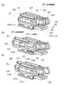
図1に工具交換装置10の外観図を示す。
図1は工具交換ユニットを3基、平行に配設した例であり、その数に制限はない。
各工具交換ユニットは共通する符号にて説明する。
工具交換ユニットはベース部材11に長手方向にスライド制御された工具保持部材12を取り付けてある。
工具保持部材12の前側端部に工具Tを保持する保持手段として、クランプ14を取り付けてある。
FIG. 1 shows an external view of the tool changer 10.
FIG. 1 shows an example in which three tool change units are arranged in parallel, and the number thereof is not limited.
Each tool change unit will be described with a common symbol.
In the tool change unit, a
A
本実施例では、スライド機構としてLMレール11aとLMブロック12aとからなるLMガイドを採用し、エアシリンダー13のロッド13aを工具保持部材12の後端部に連結した例になっている。
工具保持部材12は上部側に両側からブラケット17a〜17cを立設し、上部にケース部17を設けて、ケース部17の下側の空間部に工具Tを収容する例になっている。
このケース部17の内部には、工具Tの有無を感知するセンサー部18及びエアーブローノズル等が配設されている。
従って、これらのケーブルや配管類を移動保持するのに屈曲性架台15にてケース部17と連結してある。
屈曲性架台としては、例えばケーブルベア(登録商標)を用いることができる。
屈曲性架台15には近接ドック16が取り付けられていて、図示を省略した近接スイッチにより、前進位置と後退位置が制御されている。
なお、屈曲性架台15の下側端部は図示を省略したブラケットにて固定されている。
ここで、感知センサー18は工具が保持されているか否かをチェックするためのものであり、エアーブローノズルは工具交換ユニット内に戻された工具をエアーブローし、切粉等を除去するためのものである。
In this embodiment, an LM guide comprising an
The
Inside the
Therefore, in order to move and hold these cables and pipes, the
For example, a cable bear (registered trademark) can be used as the flexible mount.
A
Note that the lower end of the
Here, the
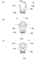
図3に工具の保持手段(クランプ)の構造例を示す。
左右一対のクランプアーム14a,14aを上部が開口した状態で図示を省略したブラケットに、軸部14b,14bを用いて回動自在に取り付けてあり、バネ材14cにより上部の開口部が狭くなる方向に付勢してある。
これにより工具Tが横方向に位置した状態のまま下降すると、図3(b)のように工具Tの外周部に押圧されて挟持部14d,14dの間が開く。
さらに下降させると図3(c)に示すように工具Tの側部が、円弧状の挟持部14d,14dの間に挟持され、工具Tが保持される。
なお、工具Tを取り外すには逆の工程を行う。
FIG. 3 shows an example of the structure of the tool holding means (clamp).
A pair of left and
As a result, when the tool T descends while being positioned in the lateral direction, it is pressed against the outer peripheral portion of the tool T as shown in FIG.
When further lowered, the side portion of the tool T is sandwiched between the arc-
To remove the tool T, the reverse process is performed.
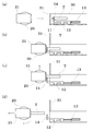
次に図2に基づいて刃物台20の工具軸21に工具を引き渡す工程を説明する。
図2は、工具交換ユニットのケース部17,ブラケット17a〜17c及び屈曲性架台15等の表示を省略し、工具の動きのみを表示した。
工具軸21は工具Tをチャックし、機械加工に供するものであり、刃物台20に旋回制御された状態で取り付けられている。
刃物台20は加工エリアにおいて、直交座標X,Y,Z軸方向に移動制御されている。
工具交換装置10は加工以外のエリア30とシャッター31にて区切られている。
図2(a)に示すように工具軸21の接近動作と連動してシャッター31が開き、エアシリンダー13の作動により工具保持部材12が所定の前進位置まで前進する。
この状態で図2(b)に示すように工具軸21が工具のシャンクをチャックする。
次に図2(c)に示すように刃物台20が上昇すると工具Tがクランプ14から外れる。
これにより、図2(d)に示すように工具Tが工具軸21に引き渡される。
なお、工具軸21から工具Tを工具交換装置に戻す場合には、これとは逆の工程を経ることになる。
Next, a process of delivering the tool to the
FIG. 2 omits the display of the
The
The
The tool changer 10 is divided by an
As shown in FIG. 2A, the
In this state, the
Next, as shown in FIG. 2C, the tool T is detached from the
As a result, the tool T is delivered to the
Note that when the tool T is returned from the
10 工具交換装置
11 ベース部材
12 工具保持部材
13 シリンダー
14 クランプ
10
Claims (5)
前記工具保持部材を長手方向にスライド支持したベース部材と、
前記工具保持部材の位置をスライド制御する制御手段とを備えた工具交換ユニットからなることを特徴とする工具交換装置。 A tool holding member for accommodating and holding the long tool in the longitudinal direction by the holding means;
A base member that slide-supports the tool holding member in the longitudinal direction;
A tool changer comprising a tool change unit provided with a control means for slidingly controlling the position of the tool holding member.
前記工具の挟持部は工具をクランプ挟持する方向に付勢されていることを特徴とする請求項1又は2記載の工具交換装置。 The holding means has a clamping part of a tool whose upper part opens on the upper side of a pair of clamp arms,
The tool changer according to claim 1 or 2, wherein the clamping part of the tool is biased in a direction of clamping the tool.
前記工具交換ユニットは加工エリア以外に設けられていることを特徴とする請求項1〜3のいずれかに記載の工具交換装置。 Has a shutter that divides the processing area and other than the processing area,
The tool changer according to any one of claims 1 to 3, wherein the tool change unit is provided outside a machining area.
前記シャッターを開くステップと、
前記複数の工具交換ユニットから必要な工具を保持している工具交換ユニットを選択するステップと、
前記選択された工具交換ユニットの工具保持部材を長手方向に前進させた状態で刃物台を前記工具側に移動させて当該刃物台に有する工具軸に前記工具のシャンクをチャックさせるステップと、
前記刃物台を上昇させて工具を前記クランプから離脱させるステップとを有することを特徴とする工具の交換方法。 A tool changing method using the tool changing device according to claim 4,
Opening the shutter;
Selecting a tool change unit holding a required tool from the plurality of tool change units;
Moving the tool rest to the tool side in a state where the tool holding member of the selected tool change unit is advanced in the longitudinal direction, and chucking the shank of the tool on the tool axis of the tool rest;
And a step of raising the tool post and releasing the tool from the clamp.
Priority Applications (5)
| Application Number | Priority Date | Filing Date | Title |
|---|---|---|---|
| JP2016086007A JP6886166B2 (en) | 2016-04-22 | 2016-04-22 | Tool changer and change method |
| TW106204913U TWM548608U (en) | 2016-04-22 | 2017-04-10 | Tool-changing device |
| US15/487,907 US10661403B2 (en) | 2016-04-22 | 2017-04-14 | Tool changer, machine tool, and method for changing tool |
| EP17167005.2A EP3235591B1 (en) | 2016-04-22 | 2017-04-19 | Tool changer, machine tool, and method for changing tool |
| CN201720412896.3U CN206748041U (en) | 2016-04-22 | 2017-04-19 | Tool replacing apparatus |
Applications Claiming Priority (1)
| Application Number | Priority Date | Filing Date | Title |
|---|---|---|---|
| JP2016086007A JP6886166B2 (en) | 2016-04-22 | 2016-04-22 | Tool changer and change method |
Publications (2)
| Publication Number | Publication Date |
|---|---|
| JP2017193033A true JP2017193033A (en) | 2017-10-26 |
| JP6886166B2 JP6886166B2 (en) | 2021-06-16 |
Family
ID=58579022
Family Applications (1)
| Application Number | Title | Priority Date | Filing Date |
|---|---|---|---|
| JP2016086007A Active JP6886166B2 (en) | 2016-04-22 | 2016-04-22 | Tool changer and change method |
Country Status (5)
| Country | Link |
|---|---|
| US (1) | US10661403B2 (en) |
| EP (1) | EP3235591B1 (en) |
| JP (1) | JP6886166B2 (en) |
| CN (1) | CN206748041U (en) |
| TW (1) | TWM548608U (en) |
Families Citing this family (3)
| Publication number | Priority date | Publication date | Assignee | Title |
|---|---|---|---|---|
| KR102598071B1 (en) * | 2019-03-08 | 2023-11-03 | 주식회사 디엔솔루션즈 | Auto toool changer and method for controlling the same and machine tool having the same |
| CN111015320B (en) * | 2019-12-09 | 2021-08-31 | 深圳模德宝科技有限公司 | Cutter clamping equipment |
| EP4122643B1 (en) * | 2020-03-23 | 2025-01-22 | DN Solutions Co., Ltd. | Boring bar tool changer and boring bar tool changing method using same |
Citations (12)
| Publication number | Priority date | Publication date | Assignee | Title |
|---|---|---|---|---|
| DE3136391A1 (en) * | 1981-09-14 | 1983-03-24 | Peddinghaus, Rolf, 5828 Ennepetal | Device for automatically changing a tool on a horizontal boring mill |
| JPH03161233A (en) * | 1989-11-20 | 1991-07-11 | Hitachi Seiko Ltd | Tool exchange device |
| JPH042437A (en) * | 1990-04-20 | 1992-01-07 | Hitachi Seiko Ltd | Tool change device |
| JPH10263970A (en) * | 1997-03-25 | 1998-10-06 | Okuma Mach Works Ltd | Internal cylindrical grinding machine |
| JP2005103650A (en) * | 2003-09-26 | 2005-04-21 | Makino J Kk | Tool changer |
| JP2005186186A (en) * | 2003-12-25 | 2005-07-14 | Mori Seiki Co Ltd | Tool changer for machine tools |
| JP2008023661A (en) * | 2006-07-21 | 2008-02-07 | Mitsubishi Heavy Ind Ltd | Automatic tool exchanger |
| WO2008050023A1 (en) * | 2006-10-20 | 2008-05-02 | Comau France | Device for storing, loading and unloading tools, particularly special tools |
| JP2009178804A (en) * | 2008-01-31 | 2009-08-13 | Mori Seiki Co Ltd | Machine tool having a boring bar magazine and boring bar magazine |
| JP2012148382A (en) * | 2011-01-20 | 2012-08-09 | Koyo Mach Ind Co Ltd | Automatic tool changer |
| JP2015182139A (en) * | 2014-03-20 | 2015-10-22 | 三菱重工業株式会社 | Machine tool |
| JP2017052023A (en) * | 2015-09-07 | 2017-03-16 | Dmg森精機株式会社 | Machine Tools |
Family Cites Families (6)
| Publication number | Priority date | Publication date | Assignee | Title |
|---|---|---|---|---|
| USRE25956E (en) * | 1962-07-27 | 1966-02-22 | Tool location in automatically controlled machine tools | |
| ITTO20010865A1 (en) * | 2001-09-11 | 2003-03-11 | Comau Spa | DEVICE FOR LOADING AND UNLOADING OF TOOLS IN AND FROM THE TOOL MAGAZINE OF A MACHINE TOOL. |
| JP4699111B2 (en) * | 2005-06-30 | 2011-06-08 | 有限会社ニューリー研究所 | Automatic tool changer and processing machine |
| JP4880274B2 (en) * | 2005-09-30 | 2012-02-22 | オークマ株式会社 | Machine tool cover structure |
| US8308621B2 (en) * | 2009-10-13 | 2012-11-13 | Shenq Fang Yuan Technology Co., Ltd. | Multi-spindle machining machine with tool changing mechanism |
| US9126298B2 (en) * | 2011-02-24 | 2015-09-08 | Markino Milling Machine Co., Ltd. | Machining center |
-
2016
- 2016-04-22 JP JP2016086007A patent/JP6886166B2/en active Active
-
2017
- 2017-04-10 TW TW106204913U patent/TWM548608U/en unknown
- 2017-04-14 US US15/487,907 patent/US10661403B2/en active Active
- 2017-04-19 EP EP17167005.2A patent/EP3235591B1/en active Active
- 2017-04-19 CN CN201720412896.3U patent/CN206748041U/en active Active
Patent Citations (12)
| Publication number | Priority date | Publication date | Assignee | Title |
|---|---|---|---|---|
| DE3136391A1 (en) * | 1981-09-14 | 1983-03-24 | Peddinghaus, Rolf, 5828 Ennepetal | Device for automatically changing a tool on a horizontal boring mill |
| JPH03161233A (en) * | 1989-11-20 | 1991-07-11 | Hitachi Seiko Ltd | Tool exchange device |
| JPH042437A (en) * | 1990-04-20 | 1992-01-07 | Hitachi Seiko Ltd | Tool change device |
| JPH10263970A (en) * | 1997-03-25 | 1998-10-06 | Okuma Mach Works Ltd | Internal cylindrical grinding machine |
| JP2005103650A (en) * | 2003-09-26 | 2005-04-21 | Makino J Kk | Tool changer |
| JP2005186186A (en) * | 2003-12-25 | 2005-07-14 | Mori Seiki Co Ltd | Tool changer for machine tools |
| JP2008023661A (en) * | 2006-07-21 | 2008-02-07 | Mitsubishi Heavy Ind Ltd | Automatic tool exchanger |
| WO2008050023A1 (en) * | 2006-10-20 | 2008-05-02 | Comau France | Device for storing, loading and unloading tools, particularly special tools |
| JP2009178804A (en) * | 2008-01-31 | 2009-08-13 | Mori Seiki Co Ltd | Machine tool having a boring bar magazine and boring bar magazine |
| JP2012148382A (en) * | 2011-01-20 | 2012-08-09 | Koyo Mach Ind Co Ltd | Automatic tool changer |
| JP2015182139A (en) * | 2014-03-20 | 2015-10-22 | 三菱重工業株式会社 | Machine tool |
| JP2017052023A (en) * | 2015-09-07 | 2017-03-16 | Dmg森精機株式会社 | Machine Tools |
Also Published As
| Publication number | Publication date |
|---|---|
| EP3235591A1 (en) | 2017-10-25 |
| CN206748041U (en) | 2017-12-15 |
| TWM548608U (en) | 2017-09-11 |
| US10661403B2 (en) | 2020-05-26 |
| JP6886166B2 (en) | 2021-06-16 |
| EP3235591B1 (en) | 2022-03-23 |
| US20170304973A1 (en) | 2017-10-26 |
Similar Documents
| Publication | Publication Date | Title |
|---|---|---|
| JP5956040B1 (en) | Machine Tools | |
| US10160077B2 (en) | Tool changing system and method | |
| US20180104781A1 (en) | Workpiece loader device | |
| CN104070394B (en) | Lathe | |
| JP2009034803A (en) | Machine tool with automatic tool changer | |
| WO2014084376A1 (en) | Machine tool | |
| JP6212905B2 (en) | Machine Tools | |
| KR20160061052A (en) | Apparatus for machining profile | |
| JP6886166B2 (en) | Tool changer and change method | |
| US20210101237A1 (en) | Tool Changing System of a Machining Center and Method for Controlling the Same | |
| KR102562067B1 (en) | Magazine for long boring bar and machine tool having the same | |
| JP2010131719A (en) | Tool breakage detection device | |
| JP2009034801A (en) | Arm type loader | |
| CN116619100A (en) | A CNC machine tool changer | |
| JP4330413B2 (en) | Automatic tool changer | |
| US9844850B2 (en) | Machine tool | |
| CN103203644A (en) | Multitasking Machine Tool | |
| JP6230684B1 (en) | Processing equipment | |
| KR20230130274A (en) | Tool change device of machine tools | |
| CN113020990B (en) | Automatic production line for motorcycle cylinder | |
| JP2008296294A (en) | Pallet changer | |
| JPH10235495A (en) | Method for clamping pipe of pipe working equipment and device therefor | |
| JP4332597B2 (en) | Drilling device | |
| WO2020090055A1 (en) | Machine tool | |
| CN210910235U (en) | Square pipe positioning device and square pipe cutting system with same |
Legal Events
| Date | Code | Title | Description |
|---|---|---|---|
| A621 | Written request for application examination |
Free format text: JAPANESE INTERMEDIATE CODE: A621 Effective date: 20190401 |
|
| A977 | Report on retrieval |
Free format text: JAPANESE INTERMEDIATE CODE: A971007 Effective date: 20200129 |
|
| A131 | Notification of reasons for refusal |
Free format text: JAPANESE INTERMEDIATE CODE: A131 Effective date: 20200302 |
|
| A521 | Request for written amendment filed |
Free format text: JAPANESE INTERMEDIATE CODE: A523 Effective date: 20200330 |
|
| A131 | Notification of reasons for refusal |
Free format text: JAPANESE INTERMEDIATE CODE: A131 Effective date: 20200907 |
|
| A521 | Request for written amendment filed |
Free format text: JAPANESE INTERMEDIATE CODE: A523 Effective date: 20201009 |
|
| TRDD | Decision of grant or rejection written | ||
| A01 | Written decision to grant a patent or to grant a registration (utility model) |
Free format text: JAPANESE INTERMEDIATE CODE: A01 Effective date: 20210506 |
|
| A61 | First payment of annual fees (during grant procedure) |
Free format text: JAPANESE INTERMEDIATE CODE: A61 Effective date: 20210507 |
|
| R150 | Certificate of patent or registration of utility model |
Ref document number: 6886166 Country of ref document: JP Free format text: JAPANESE INTERMEDIATE CODE: R150 |
|
| R250 | Receipt of annual fees |
Free format text: JAPANESE INTERMEDIATE CODE: R250 |