JP2017193352A - cap - Google Patents

cap Download PDF

Info

Publication number
JP2017193352A
JP2017193352A JP2016084473A JP2016084473A JP2017193352A JP 2017193352 A JP2017193352 A JP 2017193352A JP 2016084473 A JP2016084473 A JP 2016084473A JP 2016084473 A JP2016084473 A JP 2016084473A JP 2017193352 A JP2017193352 A JP 2017193352A
Authority
JP
Japan
Prior art keywords
annular valve
container
valve seat
annular
cap
Prior art date
Legal status (The legal status is an assumption and is not a legal conclusion. Google has not performed a legal analysis and makes no representation as to the accuracy of the status listed.)
Pending
Application number
JP2016084473A
Other languages
Japanese (ja)
Inventor
孝陽 崎村
Takaaki Sakimura
孝陽 崎村
佐々木 昌
Akira Sasaki
昌 佐々木
植平 庄治
Shoji Uehira
庄治 植平
悟 市川
Satoru Ichikawa
悟 市川
Current Assignee (The listed assignees may be inaccurate. Google has not performed a legal analysis and makes no representation or warranty as to the accuracy of the list.)
Tokyo Light Industry Co Ltd
Original Assignee
Tokyo Light Industry Co Ltd
Priority date (The priority date is an assumption and is not a legal conclusion. Google has not performed a legal analysis and makes no representation as to the accuracy of the date listed.)
Filing date
Publication date
Application filed by Tokyo Light Industry Co Ltd filed Critical Tokyo Light Industry Co Ltd
Priority to JP2016084473A priority Critical patent/JP2017193352A/en
Publication of JP2017193352A publication Critical patent/JP2017193352A/en
Pending legal-status Critical Current

Links

Images

Landscapes

  • Closures For Containers (AREA)

Abstract

PROBLEM TO BE SOLVED: To provide a cap capable of returning a part of a content not discharged into a container after use of the content, and sealing the inside of the container after a short time.SOLUTION: A cap body comprises: a discharge passage for discharging a content in a container; a communication hole 25 communicating the discharge passage with a container mouth part; an annular valve seat 26 provided around the communication hole 25; and a check valve which opens and closes the communication hole 26 by seating or separating an annular valve part on or from the annular valve seat 26. A protrusion 27 extending in a radial direction and protruding with a smooth curved surface is formed at a position of the annular valve seat 26 on the opposite side of a hinge 6. As a result, a part of the content not discharged is returned into the container through a gap around the protrusion 27 between the annular valve part and the annular valve seat 26 after use of the content, and the inside of the container can be sealed after a short time.SELECTED DRAWING: Figure 2

Description

本発明は、合成樹脂から成形されたキャップ、特に、醤油等の液状内容物または粘性を有する流動性内容物が充填される容器の容器口部に装着され、容器内の圧力により開閉するキャップに関するものである。   The present invention relates to a cap molded from a synthetic resin, and more particularly to a cap that is attached to a container mouth portion of a container filled with a liquid content such as soy sauce or a fluid content having viscosity, and that opens and closes by the pressure in the container. Is.

上述した内容物の使用後、キャップの締着が弱いと、容器内の密封状態を維持できず容器内に空気または菌類等が入り、内容物の酸化またはカビ等の繁殖をきたし劣化を早めるなどの問題があった。これを解決するために、容器口部に装着されるキャップには、容器の胴部を圧搾して容器に内圧を加え、適量の内容物を使用した直後、使用者が手でキャップを操作することなく容器内(容器の口部)を密封するものが提案されている。   If the cap is weak after using the above-mentioned contents, the sealed state inside the container cannot be maintained, and air or fungi will enter the container, causing the contents to oxidize or proliferate, etc. There was a problem. In order to solve this problem, the cap attached to the container mouth is squeezed into the body of the container to apply internal pressure to the container, and the user operates the cap by hand immediately after using an appropriate amount of contents. There has been proposed one that seals the inside of the container (the mouth of the container) without any problems.

例えば、特許文献1には、容器口部に嵌合されるキャップ本体は、前記容器口部に連通する吐出通路と、該吐出通路内に嵌合して、吐出孔を有するベース部と、該ベース部上に配置され、前記吐出孔からの内容物の吐出だけを許容する逆止弁と、を備え、該逆止弁は、前記吐出通路内に嵌合される円筒部と、該円筒部の内壁面から間隙を形成するように中心に向かって放射状に延びる弾性変形可能な複数の弾性片と、該各弾性片の先端に一体に接続され、前記吐出孔の吐出方向下流側にあって、該吐出孔を開閉する弁部材とから構成され、容器への内圧が解除されると、逆止弁の各弾性片が復元するために、弁部材が吐出孔を塞ぎ容器内を密封状態に維持することが開示されている。   For example, in Patent Document 1, a cap main body fitted to a container mouth portion includes a discharge passage communicating with the container mouth portion, a base portion fitted into the discharge passage and having a discharge hole, A check valve disposed on the base portion and allowing only discharge of the contents from the discharge hole, the check valve being fitted into the discharge passage, and the cylindrical portion A plurality of elastically deformable elastic pieces extending radially toward the center so as to form a gap from the inner wall surface thereof, and integrally connected to the tips of the respective elastic pieces, and downstream of the discharge holes in the discharge direction. And the valve member that opens and closes the discharge hole, and when the internal pressure to the container is released, each elastic piece of the check valve is restored, so that the valve member closes the discharge hole and seals the inside of the container It is disclosed to maintain.

しかしながら、特許文献1の発明では、内容物を吐出した後、逆止弁が作動することで、吐出通路から吐出されなかった内容物が容器内に戻らずに吐出通路内に残存することになり、蓋体を閉めるときに、蓋体の円筒状閉塞部により内容物が飛散する虞があり、しかも、蓋体を閉めて再び開けると、蓋体の円筒状閉塞部に内容物が付着する虞もあり、改善する必要があった。   However, in the invention of Patent Document 1, after the contents are discharged, the check valve is operated so that the contents not discharged from the discharge passage remain in the discharge passage without returning to the container. When the lid is closed, the contents may be scattered by the cylindrical closed portion of the lid, and when the lid is closed and reopened, the contents may adhere to the cylindrical closed portion of the lid There was also a need to improve.

そこで、これを対策すべき提案された従来技術として特許文献2には、容器口部を閉塞する中栓部材と、該中栓部材を覆うとともに内容物を吐出する吐出口が形成された有頂筒状の本体筒部材と、を備え、中栓部材には、吐出口と容器内とを連通する連通孔が形成され、連通孔内には、当該連通孔の軸線方向に沿って弾性変位して当該連通孔を開閉する弁体部が配設され、弁体部の弁座のうち当該弁体部と接触する部位の一部に、内容物の流通を許容する流通許容溝が形成される吐出キャップであって、内容物を吐出した後、吐出口から外部に吐出されなかった内容物を、この流通許容溝から容器内に戻すことが開示されている。   In view of this, Patent Document 2 as a proposed prior art that should take measures against this has an inner plug member that closes the container opening, and a discharge port that covers the inner plug member and discharges the contents. A tubular body body member, and the inner plug member is formed with a communication hole that communicates the discharge port and the inside of the container. The communication hole is elastically displaced along the axial direction of the communication hole. The valve body part for opening and closing the communication hole is disposed, and a flow allowing groove for allowing the content to flow is formed in a part of the valve seat of the valve body part in contact with the valve body part. It is a discharge cap, and after discharging the contents, it is disclosed to return the contents that have not been discharged to the outside from the discharge port into the container through the flow allowance groove.

特開2013−241197号公報JP 2013-241197 A 特開2015−155333号公報JP2015-155333A

しかしながら、特許文献2に係る発明では、弁体部が弁座に着座した最終段階において、内容物による表面張力により閉鎖される流通許容溝が採用されているが、この作用効果を得るべく流通許容溝の具体的な形状を特定することは非常に難しく、その形状が相当複雑化する虞がある。さらに、内容物の種類が様々であり、内容物の種類(内容物の粘度)によって、流通許容溝の具体的な形状をそれぞれ特定する必要もあり、採用することはできない。   However, in the invention according to Patent Document 2, a flow-permissible groove that is closed by the surface tension due to the contents is adopted at the final stage when the valve body is seated on the valve seat. It is very difficult to specify the specific shape of the groove, and the shape may be considerably complicated. Furthermore, there are various kinds of contents, and it is necessary to specify the specific shape of the flow-permissible groove depending on the kind of contents (the viscosity of the contents), which cannot be adopted.

本発明は、かかる点に鑑みてなされたものであり、形状が複雑となる流通溝相当を採用することなく、内容物の使用後、外部に吐出されなかった内容物の一部を容器内に戻し、僅かな時間後に容器内を密封状態にすることができるキャップを提供することを目的とする。   The present invention has been made in view of such a point, and without adopting the equivalent of a distribution groove having a complicated shape, a part of the content that has not been discharged to the outside after use of the content is contained in the container. An object of the present invention is to provide a cap capable of returning and sealing the inside of the container after a short time.

本発明は、上記課題を解決するための手段として、請求項1に記載した発明は、容器口部に装着する筒状のキャップ本体を備えた、合成樹脂製のキャップであって、前記キャップ本体は、容器内の内容物を吐出する吐出通路と、該吐出通路と前記容器口部とを連通する連通孔と、該連通孔周辺に設けられた環状弁座と、前記連通孔の軸線方向に沿って弾性変位して、環状弁部が前記環状弁座に着座または離脱することで前記連通孔を開閉する逆止弁と、を備え、前記環状弁部と前記環状弁座との、いずれか一方または両方の接触面に径方向に延び、なだらかな曲面で突設される凸部が形成されており、前記容器口部に前記キャップが装着され、容器内の内容物を使用後、前記環状弁部が前記環状弁座へ着座した初期段階では、前記環状弁部と前記環状弁座との間で前記凸部周辺に隙間が現出され、その後時間の経過に伴って前記隙間が閉塞されることを特徴とするものである。
請求項1の発明では、内容物の使用時には、容器の胴部を圧搾して容器に内圧を加えれば、容器の内圧により逆止弁が連通孔の軸線方向に沿って弾性変位して、環状弁部が環状弁座から離脱すると共に連通孔が開放され、内容物が連通孔を介して吐出通路から外部に吐出される。一方、容器への内圧が解除されると、逆止弁が復元して環状弁部が環状弁座に着座するために、連通孔が閉塞されて、速やかに、容器内を密封状態に維持でき、空気の容器内への流入を抑制することができる。
As a means for solving the above-mentioned problems, the present invention described in claim 1 is a cap made of synthetic resin provided with a cylindrical cap body to be attached to a container mouth, wherein the cap body Is a discharge passage for discharging the contents in the container, a communication hole for communicating the discharge passage and the container opening, an annular valve seat provided around the communication hole, and an axial direction of the communication hole. And a check valve that opens and closes the communication hole when the annular valve portion is seated on or removed from the annular valve seat, and is either of the annular valve portion and the annular valve seat. One or both contact surfaces are formed with a convex portion that extends in the radial direction and protrudes with a gently curved surface, the cap is attached to the container mouth, and the annular shape is used after the contents in the container are used. In the initial stage when the valve portion is seated on the annular valve seat, the annular valve portion and Serial is revealing a gap surrounding the projecting portion with the annular valve seat, in which the gap then with the passage of time, characterized in that it is closed.
According to the first aspect of the present invention, when the contents are used, if the body portion of the container is squeezed and an internal pressure is applied to the container, the check valve is elastically displaced along the axial direction of the communication hole by the internal pressure of the container. The valve part is detached from the annular valve seat and the communication hole is opened, and the contents are discharged from the discharge passage to the outside through the communication hole. On the other hand, when the internal pressure on the container is released, the check valve is restored and the annular valve portion is seated on the annular valve seat, so the communication hole is closed and the container can be quickly kept sealed. Inflow of air into the container can be suppressed.

特に、容器への内圧が解除されると、内圧解除による吸引力及び弾性力によって、逆止弁の環状弁部が環状弁座に向かって変位して着座するが、その着座した初期段階では、環状弁部と環状弁座との間の凸部周辺に極小の隙間が現出される僅かな時間が得られる。この僅かな時間に、外部に吐出されなかった内容物の一部が、当該隙間から容器内に戻るようになる。その後次第に、内圧解除による吸引力及び環状弁部から環状弁座への押圧力により、環状弁部と環状弁座との間の凸部周辺の隙間の開口面積が次第に減少すると共に、環状弁部と環状弁座とが互いに馴染むようにほぼ密着して、内容物の表面張力も作用することで、環状弁部と環状弁座との間の凸部周辺の隙間が閉塞されるために、容器内を密封状態に維持することができる。   In particular, when the internal pressure to the container is released, the annular valve portion of the check valve is displaced and seated toward the annular valve seat by the suction force and elastic force due to the internal pressure release, but in the initial stage of the seating, A short period of time in which a minimal gap appears around the convex portion between the annular valve portion and the annular valve seat is obtained. During this short period of time, a part of the contents that have not been discharged to the outside returns from the gap into the container. Thereafter, the opening area of the gap around the convex portion between the annular valve portion and the annular valve seat gradually decreases due to the suction force due to the release of the internal pressure and the pressing force from the annular valve portion to the annular valve seat, and the annular valve portion Since the ring valve seat and the annular valve seat are almost in close contact with each other and the surface tension of the contents also acts, the gap around the convex portion between the annular valve portion and the annular valve seat is closed. The inside can be kept sealed.

また、請求項1の発明では、環状弁座に設けた凸部は、なだらかな曲面で突設されるものであり、その形状が簡素なものとなる。しかも、内容物の種類(内容物の粘度)によって、凸部の高さ寸法及び幅寸法をそれぞれ特定すればよく、その形状が複雑化することはない。   In the first aspect of the invention, the convex portion provided on the annular valve seat protrudes with a gentle curved surface, and the shape thereof is simple. In addition, the height dimension and width dimension of the convex portion may be specified depending on the type of content (viscosity of the content), and the shape is not complicated.

請求項2に記載した発明は、請求項1に記載した発明において、前記環状弁部の径方向に沿う幅寸法W1は、前記環状弁座の径方向に沿う幅寸法W2よりも小さいことを特徴とするものである。
請求項2の発明では、容器への内圧が解除され、外部に吐出されなかった内容物の一部が、環状弁部と環状弁座との間の隙間から容器内に戻った後、環状弁部と環状弁座との間の密着性を向上させることができる。
The invention described in claim 2 is the invention described in claim 1, wherein the width dimension W1 along the radial direction of the annular valve portion is smaller than the width dimension W2 along the radial direction of the annular valve seat. It is what.
In the invention of claim 2, after the internal pressure to the container is released and a part of the contents not discharged to the outside returns to the container from the gap between the annular valve portion and the annular valve seat, the annular valve The adhesion between the part and the annular valve seat can be improved.

請求項3に記載した発明は、請求項1または2に記載した発明において、前記逆止弁を成形する合成樹脂は、前記環状弁座を成形する合成樹脂よりも高弾性であることを特徴とするものである。
請求項3の発明では、容器への内圧が解除され、外部に吐出されなかった内容物の一部が、環状弁部と環状弁座との間の隙間から容器内に戻った後の、環状弁部と環状弁座との間の密着性をさらに向上させることができる。
The invention described in claim 3 is characterized in that, in the invention described in claim 1 or 2, the synthetic resin for molding the check valve is more elastic than the synthetic resin for molding the annular valve seat. To do.
In the invention of claim 3, the internal pressure to the container is released, and a part of the contents not discharged to the outside is returned to the container from the gap between the annular valve part and the annular valve seat. The adhesion between the valve portion and the annular valve seat can be further improved.

本発明のキャップによれば、形状が複雑となる流通溝相当を採用することなく、内容物の使用後は、吐出されなかった内容物の一部を容器内に戻し、僅かな時間後に容器内を密封状態にすることができる。   According to the cap of the present invention, after using the contents, a part of the contents which have not been discharged are returned to the container without using an equivalent of a distribution groove having a complicated shape, and after a short time, Can be sealed.

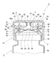
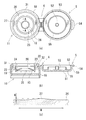
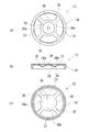
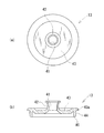
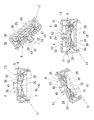
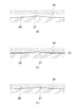
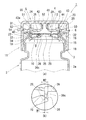
図1は、本発明の実施形態に係るキャップの断面図である。FIG. 1 is a cross-sectional view of a cap according to an embodiment of the present invention. 図2の(a)は、図1の、蓋体を含む主キャップ体の平面図であり、(b)は、(a)の断面図であり、(c)は、(a)のA−A線に沿う拡大断面図である。2A is a plan view of the main cap body including the lid body in FIG. 1, FIG. 2B is a cross-sectional view of FIG. 2A, and FIG. It is an expanded sectional view which follows an A line. 図3の(a)は、図1の、逆止弁の平面図であり、(b)は、(a)の断面図であり、(c)は下面図である。3A is a plan view of the check valve of FIG. 1, FIG. 3B is a cross-sectional view of FIG. 3A, and FIG. 3C is a bottom view. 図4(a)は、図1の、案内筒状体の平面図であり、(b)は、(a)の断面図である。4A is a plan view of the guide cylindrical body of FIG. 1, and FIG. 4B is a cross-sectional view of FIG. 図5は、本キャップの作用を段階的に示した図である。FIG. 5 is a view showing the operation of the cap in stages. 図6は、環状弁部が環状弁座に着座する様子を段階的に示す図である。FIG. 6 is a diagram showing in a stepwise manner how the annular valve portion is seated on the annular valve seat. 図7(a)は、他の実施形態に係るキャップの断面図であり、(b)は(a)のB部拡大図である。Fig.7 (a) is sectional drawing of the cap which concerns on other embodiment, (b) is the B section enlarged view of (a).

以下、本発明を実施するための形態を図1〜図7に基づいて詳細に説明する。
本発明の実施形態に係るキャップ1は、図1に示すように、容器2の容器口部3に嵌合され、内容物の連通孔25を有するキャップ本体4と、該キャップ本体4に被冠する蓋体5とから構成される。キャップ本体4の一部を構成する主キャップ体11に、蓋体5がヒンジ6を介して一体的に接続される。本キャップ1は、図2に示す蓋体5を含む主キャップ体11と、図3に示す逆止弁12と、図4に示す案内筒状体13との三つの構成部材を組み立てて構成される。なお、蓋体5を、ヒンジ6を介して主キャップ体11に接続せずに、蓋体5を別体として構成してもよい。
Hereinafter, embodiments for carrying out the present invention will be described in detail with reference to FIGS.
As shown in FIG. 1, a cap 1 according to an embodiment of the present invention is fitted into a container mouth 3 of a container 2 and has a communication hole 25 for contents, and the cap body 4 is crowned. And the lid body 5 to be configured. A lid 5 is integrally connected to a main cap 11 constituting a part of the cap body 4 via a hinge 6. The cap 1 is constructed by assembling three constituent members: a main cap body 11 including the lid body 5 shown in FIG. 2, a check valve 12 shown in FIG. 3, and a guide cylindrical body 13 shown in FIG. The The lid 5 may be configured as a separate body without connecting the lid 5 to the main cap body 11 via the hinge 6.

図1に示すように、容器2は、例えばチューブ容器など変形し易い容器であり、その内部には液状内容物や粘性を有する流動性内容物が充填される。この内容物は、例えば、醤油、オリーブオイル、ドレッシング、マヨネーズ、ケチャップ、とんかつ用ソース、ペースト状マスタード等が挙げられる。容器2は、その胴部2aを圧搾するなどして内圧を加えることで内容物を吐出させるタイプのものである。容器口部3は、円筒状に形成される。該容器口部3の下部外壁面には嵌合突条部15が形成される。容器口部3の上部には、周壁部全体が内方に凹む嵌合凹条部16が形成される。なお、本キャップ1は、外容器と内容器とからなる二重容器(剥離容器と言われるものも含む)にも採用することができ、外容器の容器口部3に装着される。内容器は、その内部に内容物が充填されると共に内容物の減少に伴いしぼみ変形する可撓性を有するものである。内容器の減容形状を保持するために外容器と内容器との間に外気が吸入されるように、外容器に吸入弁が取り付けられる。   As shown in FIG. 1, the container 2 is a container that is easily deformed, such as a tube container, and is filled with a liquid content or a fluid content having viscosity. Examples of the contents include soy sauce, olive oil, dressing, mayonnaise, ketchup, tonkatsu sauce, pasty mustard and the like. The container 2 is of a type in which contents are discharged by applying an internal pressure by, for example, squeezing the body 2a. The container mouth 3 is formed in a cylindrical shape. A fitting protrusion 15 is formed on the lower outer wall surface of the container mouth 3. On the upper part of the container mouth portion 3, a fitting groove portion 16 in which the entire peripheral wall portion is recessed inward is formed. In addition, this cap 1 can also be employ | adopted also as the double container (including what is called a peeling container) which consists of an outer container and an inner container, and is mounted | worn with the container mouth part 3 of an outer container. The inner container is flexible so that it is filled with the contents and deforms as the contents decrease. A suction valve is attached to the outer container so that the outside air is sucked between the outer container and the inner container in order to maintain the volume reduction shape of the inner container.

図1に示すように、キャップ本体4は、容器2内の内容物を吐出する吐出通路41を有する案内筒状体13と、吐出通路41と容器口部3とを連通する連通孔25及び該連通孔25周辺に設けられた環状弁座26を有する主キャップ体11と、連通孔25の軸線方向に沿って弾性変位して、弁本体36の環状弁部29が環状弁座26から離脱または着座して連通孔25を開閉する逆止弁12と、から構成される。逆止弁12を成形する合成樹脂は、蓋体5を含む主キャップ体11を成形する合成樹脂よりも高弾性となる。具体的には、蓋体5を含む主キャップ体11及び案内筒状体13は、ポリプロピレンやポリエチレン等の樹脂にて成形される。また、逆止弁12は柔軟で高弾性の低密度ポリエチレンやエラストマー及びこれらの混合樹脂にて成形される。   As shown in FIG. 1, the cap body 4 includes a guide cylindrical body 13 having a discharge passage 41 for discharging the contents in the container 2, a communication hole 25 that connects the discharge passage 41 and the container mouth 3, and the The main cap body 11 having the annular valve seat 26 provided around the communication hole 25 and elastically displaced along the axial direction of the communication hole 25, the annular valve portion 29 of the valve body 36 is detached from the annular valve seat 26 or And a check valve 12 that is seated to open and close the communication hole 25. The synthetic resin for molding the check valve 12 is more elastic than the synthetic resin for molding the main cap body 11 including the lid 5. Specifically, the main cap body 11 and the guide cylindrical body 13 including the lid body 5 are formed of a resin such as polypropylene or polyethylene. The check valve 12 is formed of a flexible and highly elastic low-density polyethylene or elastomer and a mixed resin thereof.

図1及び図2に示すように、主キャップ体11は、容器口部3に嵌合される円筒状外側壁部18と、該円筒状外側壁部18の内側に同心状に設けられる円筒状内側壁部19と、円筒状外側壁部18の上端と円筒状内側壁部19の上端とを接続する環状水平壁部20と、を備えている。これら円筒状内側壁部19と円筒状外側壁部18との間に環状空間22が形成される。円筒状内側壁部19の上部内壁面には、周方向に沿って環状に延びる環状嵌合凹部23が形成される。   As shown in FIGS. 1 and 2, the main cap body 11 includes a cylindrical outer wall portion 18 fitted into the container mouth portion 3 and a cylindrical shape provided concentrically on the inner side of the cylindrical outer wall portion 18. The inner side wall part 19 and the annular horizontal wall part 20 which connects the upper end of the cylindrical outer wall part 18 and the upper end of the cylindrical inner wall part 19 are provided. An annular space 22 is formed between the cylindrical inner wall portion 19 and the cylindrical outer wall portion 18. The upper inner wall surface of the cylindrical inner wall portion 19 is formed with an annular fitting recess 23 extending annularly along the circumferential direction.

円筒状内側壁部19の下部内壁面には、その周方向全域から一体的に環状壁部10が径方向中心に向かって斜め上方に延びている。すなわち環状壁部10は、円筒状内側壁部19の下部内壁面から一体的に截頭円錐状で延びている。環状壁部10と円筒状内側壁部19の内壁面とにより上方を開放した空間24が形成される。環状壁部10の径方向中心部に略円形状の連通孔25が開口される。該連通孔25は容器口部3内と連通される。該連通孔25はφ5.0mm〜φ12.0mmの範囲で形成される。該連通孔25の周辺、詳しくは連通孔25の内壁面の略全域が環状弁座26として作用する。該環状弁座26は倒立円錐状面(上方に拡径した環状テーパ面やすり鉢状面)にて形成される。   On the lower inner wall surface of the cylindrical inner wall portion 19, the annular wall portion 10 integrally extends obliquely upward from the entire circumferential direction toward the radial center. That is, the annular wall portion 10 integrally extends from the lower inner wall surface of the cylindrical inner wall portion 19 in a truncated cone shape. A space 24 having an open top is formed by the annular wall portion 10 and the inner wall surface of the cylindrical inner wall portion 19. A substantially circular communication hole 25 is opened at the radial center of the annular wall 10. The communication hole 25 communicates with the inside of the container mouth portion 3. The communication hole 25 is formed in the range of φ5.0 mm to φ12.0 mm. The periphery of the communication hole 25, specifically the substantially entire area of the inner wall surface of the communication hole 25, acts as the annular valve seat 26. The annular valve seat 26 is formed by an inverted conical surface (an annular tapered surface or a bowl-shaped surface expanded upward).

図2(a)、(c)に示すように、環状弁座26の、ヒンジ6とは反対側の位置に凸部27が径方向に沿って延びている。凸部27は、環状弁座26の径方向全域に延びている。凸部27は、なだらかな曲面で突設される。凸部27の高さ寸法Hは、0.03mm〜0.25mmの範囲内で適宜設定される。また、凸部27の幅寸法Wは、0.2mm〜5.0mmの範囲内で適宜設定される。凸部27の高さ寸法H及び幅寸法Wは、該凸部27がなだらかな曲面を形成するように配慮して、着座時、環状弁部29が凸部27の表面に沿って接触するに適した形状を選択すると共に、容器2に充填される内容物の粘度に応じて適宜設定される。   As shown in FIGS. 2A and 2C, a convex portion 27 extends in the radial direction at a position on the opposite side of the annular valve seat 26 from the hinge 6. The convex portion 27 extends in the entire radial direction of the annular valve seat 26. The convex portion 27 protrudes with a gentle curved surface. The height dimension H of the convex part 27 is appropriately set within a range of 0.03 mm to 0.25 mm. Moreover, the width dimension W of the convex part 27 is suitably set within the range of 0.2 mm-5.0 mm. The height dimension H and the width dimension W of the convex portion 27 are set so that the annular valve portion 29 contacts the surface of the convex portion 27 when seated, taking into consideration that the convex portion 27 forms a gentle curved surface. While selecting a suitable shape, it sets suitably according to the viscosity of the content with which the container 2 is filled.

図1及び図2に示すように、環状水平壁部20の外径は円筒状外側壁部18の外径より小径で、その外壁面に周方向に沿って環状に延びる突条係止部31が形成される。該環状水平壁部20の外壁面に蓋体5が嵌合される。環状水平壁部20の下面には、円筒状外側壁部18の内側に、容器口部3の上端が嵌合される円筒状嵌合部32が垂設される。円筒状嵌合部32は、円筒状外側壁部18と同心状に垂設される。   As shown in FIGS. 1 and 2, the outer diameter of the annular horizontal wall portion 20 is smaller than the outer diameter of the cylindrical outer wall portion 18, and the protrusion locking portion 31 that extends annularly along the circumferential direction on the outer wall surface. Is formed. The lid 5 is fitted to the outer wall surface of the annular horizontal wall portion 20. On the lower surface of the annular horizontal wall portion 20, a cylindrical fitting portion 32, in which the upper end of the container mouth portion 3 is fitted, is suspended inside the cylindrical outer wall portion 18. The cylindrical fitting portion 32 is suspended concentrically with the cylindrical outer wall portion 18.

図1及び図3に示すように、逆止弁12は、主キャップ体11の円筒状内側壁部19の内壁面に当接する円筒状支持部34と、該円筒状支持部34の内壁面から一体的に径方向中心に向かって延びる複数の弾性片35と、各弾性片35の先端部に一体的に接続され、連通孔25を開閉する弁本体36と、各弾性片35の間に設けられ、連通孔25からの内容物が流通する複数の流通孔37と、から構成される。   As shown in FIGS. 1 and 3, the check valve 12 includes a cylindrical support portion 34 that contacts the inner wall surface of the cylindrical inner wall portion 19 of the main cap body 11, and an inner wall surface of the cylindrical support portion 34. Provided between each elastic piece 35 and a plurality of elastic pieces 35 that integrally extend toward the center in the radial direction, a valve body 36 that is integrally connected to the tip of each elastic piece 35 and opens and closes the communication hole 25. And a plurality of flow holes 37 through which the contents from the communication holes 25 flow.

図3から解るように、弁本体36は、ドーム状部36aと、該ドーム状部36aの外周から一体的に斜め上方に延びる環状薄肉部36bとから構成される。ドーム状部36aは、その厚みが頂部から下方に向かって次第に薄肉に形成される。弁本体36の環状薄肉部36bの下端面が、環状弁座26(倒立円錐状面)に着座するように倒立円錐状面(上方に拡径した環状テーパ面やすり鉢状面)に形成される。該弁本体36の環状薄肉部36bの下端面が、環状弁部29として作用する。該環状薄肉部36bの厚みは、0.2mm〜0.5mmの範囲で適宜設定される。該弁本体36の上面には球状凸部38が突設される。
各弾性片35は、円筒状支持部34の上部内壁面から径方向中心に向かって、且つ斜め下方にやや湾曲して延びている。各弾性片35の先端部が、弁本体36の環状薄肉部36bの外周面に一体的にそれぞれ接続される。本実施形態では、弾性片35は、周方向に90°ピッチで4箇所形成され、各弾性片35間に流通孔37が90°ピッチで4箇所形成される。なお、各弾性片35の厚みは、弁本体36の環状薄肉部36bの厚みと略同一である。
As can be seen from FIG. 3, the valve body 36 includes a dome-shaped portion 36 a and an annular thin portion 36 b that integrally extends obliquely upward from the outer periphery of the dome-shaped portion 36 a. The dome-shaped portion 36a is formed so that its thickness gradually becomes thinner from the top toward the bottom. The lower end surface of the annular thin portion 36b of the valve body 36 is formed as an inverted conical surface (an annular tapered surface or bowl-shaped surface expanded upward) so as to be seated on the annular valve seat 26 (an inverted conical surface). . The lower end surface of the annular thin portion 36 b of the valve body 36 acts as the annular valve portion 29. The thickness of the annular thin portion 36b is appropriately set in the range of 0.2 mm to 0.5 mm. A spherical convex portion 38 projects from the upper surface of the valve body 36.
Each elastic piece 35 extends from the upper inner wall surface of the cylindrical support portion 34 toward the center in the radial direction and slightly curved downward. The distal end portion of each elastic piece 35 is integrally connected to the outer peripheral surface of the annular thin portion 36 b of the valve body 36. In the present embodiment, the elastic pieces 35 are formed at four positions with a 90 ° pitch in the circumferential direction, and the flow holes 37 are formed at four positions with a 90 ° pitch between the elastic pieces 35. The thickness of each elastic piece 35 is substantially the same as the thickness of the annular thin portion 36b of the valve body 36.

図1及び図4に示すように、案内筒状体13は、逆止弁12の上方に配置される。該案内筒状体13は、主キャップ体11の円筒状内側壁部19と嵌合するように下方に延びる円筒状支持部40と、円筒状支持部40の径方向中央部から上方に延び、内部に吐出通路41を有する円筒状案内部42と、円筒状支持部40の上端と円筒状案内部42の下端とを一体的に接続する環状閉鎖壁部43と、から構成される。円筒状案内部42の吐出通路41が、主キャップ体11の連通孔25に連通される。環状閉鎖壁部43には、円筒状支持部40よりも径方向外方に突設される環状鍔部43aが形成される。円筒状支持部40は、逆止弁12を構成する円筒状支持部34の上方に配置される。円筒状支持部40の周壁部の厚みと、逆止弁12の円筒状支持部34の周壁部の厚みとは略同一である。円筒状支持部40の外壁面には、周方向に延びる環状突条部44が突設される。   As shown in FIGS. 1 and 4, the guide cylindrical body 13 is disposed above the check valve 12. The guide cylindrical body 13 extends downward from a cylindrical support portion 40 extending downward so as to be fitted to the cylindrical inner wall portion 19 of the main cap body 11, and from the radial center of the cylindrical support portion 40, The cylindrical guide part 42 which has the discharge channel | path 41 inside is comprised from the annular closed wall part 43 which connects the upper end of the cylindrical support part 40, and the lower end of the cylindrical guide part 42 integrally. The discharge passage 41 of the cylindrical guide portion 42 is communicated with the communication hole 25 of the main cap body 11. The annular closing wall 43 is formed with an annular flange 43 a that protrudes radially outward from the cylindrical support 40. The cylindrical support portion 40 is disposed above the cylindrical support portion 34 constituting the check valve 12. The thickness of the peripheral wall portion of the cylindrical support portion 40 and the thickness of the peripheral wall portion of the cylindrical support portion 34 of the check valve 12 are substantially the same. On the outer wall surface of the cylindrical support portion 40, an annular protrusion 44 extending in the circumferential direction is projected.

図1及び図2に示すように、蓋体5は、主キャップ体11の円筒状外側壁部18にヒンジ6を介して一体的に接続されている。該蓋体5は、ヒンジ6を介して主キャップ体11の円筒状外側壁部18の外壁面に接続される円筒状の胴部50と、該胴部50の上端の周方向全域に一体的に接続される天面部51とから構成される。胴部50の内側には、天面部51から、案内筒状体13の抜脱を規制する円筒状規制部55が垂設される。該円筒状規制部55は胴部50と同心状に垂設される。天面部51の径方向中央部には、案内筒状体13の円筒状案内部42内の吐出通路41に緊密に嵌合する円筒状密着部52が垂設される。胴部50の下部内壁面には、周方向に環状に延びる突条係止部53が形成される。胴部50の外壁面の下部で、ヒンジ6側と反対側には、使用者が把持する把持部54が周方向に沿う所定範囲で外方に向かって突設される。   As shown in FIGS. 1 and 2, the lid 5 is integrally connected to the cylindrical outer wall portion 18 of the main cap body 11 via a hinge 6. The lid body 5 is integrated with the cylindrical body portion 50 connected to the outer wall surface of the cylindrical outer wall portion 18 of the main cap body 11 via the hinge 6 and the entire circumferential direction of the upper end of the body portion 50. It is comprised from the top | upper surface part 51 connected to. A cylindrical regulation portion 55 that regulates the removal of the guide cylindrical body 13 is suspended from the top surface portion 51 inside the trunk portion 50. The cylindrical restricting portion 55 is provided concentrically with the trunk portion 50. At the central portion in the radial direction of the top surface portion 51, a cylindrical contact portion 52 that fits tightly into the discharge passage 41 in the cylindrical guide portion 42 of the guide cylindrical body 13 is suspended. On the lower inner wall surface of the body portion 50, a protrusion locking portion 53 that extends annularly in the circumferential direction is formed. On the opposite side of the outer wall surface of the body portion 50 from the hinge 6 side, a grip portion 54 to be gripped by the user protrudes outward in a predetermined range along the circumferential direction.

次に、本キャップ1を組み立て、容器口部3に装着する方法を説明する。
まず、主キャップ体11の環状壁部10の上面に、逆止弁12を上方から組み込む。詳しくは、逆止弁12の円筒状支持部34の外壁面が主キャップ体11の円筒状内側壁部19の内壁面に沿うようにして、逆止弁12を環状壁部10の上面に配置する。すなわち、逆止弁12を、上方から環状壁部10と円筒状内側壁部19の内壁面とで囲まれた上方を開放した空間24内に組み込む。
Next, a method for assembling the cap 1 and attaching it to the container mouth 3 will be described.
First, the check valve 12 is assembled on the upper surface of the annular wall portion 10 of the main cap body 11 from above. Specifically, the check valve 12 is arranged on the upper surface of the annular wall portion 10 so that the outer wall surface of the cylindrical support portion 34 of the check valve 12 is along the inner wall surface of the cylindrical inner wall portion 19 of the main cap body 11. To do. That is, the check valve 12 is incorporated into a space 24 that is open from above and surrounded by the annular wall portion 10 and the inner wall surface of the cylindrical inner wall portion 19.

次に、案内筒状体13を、その円筒状支持部40の外壁面が主キャップ体11の円筒状内側壁部19の内壁面に沿うように、逆止弁12を上方から押し込むようにして組み込み、案内筒状体13の円筒状支持部40の外壁面に設けた環状突条部44を主キャップ体11の円筒状内側壁部19の内壁面に設けた環状嵌合凹部23に嵌合すると共に、案内筒状体13の環状鍔部43aを環状水平壁部20の上面に当接させて組み付ける。この結果、逆止弁12の弁本体36の環状弁部29(弁本体36の環状薄肉部36bの下端面)が、主キャップ11の環状弁座26(連通孔25の内壁面)に接触して、且つ弁本体36のドーム状部36aの下端縁と環状弁座26の下端縁とが一致するようになる。また、逆止弁12の弁本体36は、組み込み前の位置よりも上方に位置するために、湾曲した各弾性片35の下向きの付勢力(復元力)により、弁本体36の環状弁部29が、環状壁部10の環状弁座26を押圧するようになる。また、逆止弁12の弁本体36(連通孔25)の直上に、案内筒状体13の円筒状案内部42が位置する。これにより、キャップ本体4の組み立てが完了する。   Next, the check cylindrical valve 13 is pushed from above so that the outer wall surface of the cylindrical support portion 40 extends along the inner wall surface of the cylindrical inner wall portion 19 of the main cap body 11. The annular protrusion 44 provided on the outer wall surface of the cylindrical support portion 40 of the built-in guide cylindrical body 13 is fitted into the annular fitting recess 23 provided on the inner wall surface of the cylindrical inner wall portion 19 of the main cap body 11. At the same time, the annular flange 43a of the guide cylinder 13 is brought into contact with the upper surface of the annular horizontal wall 20 and assembled. As a result, the annular valve portion 29 (the lower end surface of the annular thin portion 36b of the valve body 36) of the valve body 36 of the check valve 12 contacts the annular valve seat 26 (the inner wall surface of the communication hole 25) of the main cap 11. In addition, the lower end edge of the dome-shaped portion 36a of the valve body 36 and the lower end edge of the annular valve seat 26 come to coincide with each other. Further, since the valve body 36 of the check valve 12 is positioned above the position before the assembly, the annular valve portion 29 of the valve body 36 is caused by the downward biasing force (restoring force) of each curved elastic piece 35. However, the annular valve seat 26 of the annular wall portion 10 is pressed. Further, the cylindrical guide portion 42 of the guide cylindrical body 13 is located immediately above the valve main body 36 (communication hole 25) of the check valve 12. Thereby, the assembly of the cap body 4 is completed.

次に、キャップ本体4に蓋体5を被冠する際には、ヒンジ6を折り曲げて蓋体5をキャップ本体4の上方から覆うように被せる。すると、蓋体5の胴部50に設けた突条係止部53が、主キャップ体11の環状水平壁部20に設けた突条係止部31を乗り越えるように係合する。これと同時に、蓋体5の天面部51に設けた円筒状密着部52が、案内筒状体13の円筒状案内部42内の吐出通路41に緊密に嵌合され、蓋体5の天面部51に設けた円筒状規制部55が、案内筒状体13の円筒状支持部40の直上に近接して位置するようになる。これにより、キャップ1の組み立てが完了する。   Next, when the cap body 4 is covered with the lid body 5, the hinge 6 is bent so that the lid body 5 is covered from above the cap body 4. Then, the protrusion locking part 53 provided in the trunk | drum 50 of the cover body 5 engages so that it may get over the protrusion locking part 31 provided in the cyclic | annular horizontal wall part 20 of the main cap body 11. FIG. At the same time, the cylindrical contact portion 52 provided on the top surface portion 51 of the lid body 5 is closely fitted to the discharge passage 41 in the cylindrical guide portion 42 of the guide cylindrical body 13, and the top surface portion of the lid body 5. The cylindrical regulation part 55 provided in 51 comes to be located close to the cylindrical support part 40 of the guide cylindrical body 13 in the vicinity. Thereby, the assembly of the cap 1 is completed.

次に、キャップ1を容器口部3に装着する際には、容器口部3の嵌合凹条部16及び嵌合突条部15を、主キャップ体11の円筒状内側壁部19と円筒状外側壁部18との間の環状空間22内に挿入して、容器口部3の上端外壁面を主キャップ体1の円筒状嵌合部32の内面に密着させるようにして、キャップ1を容器口部3に嵌合する。なお、本実施形態では、キャップ1を容器口部3へ打栓方式で装着する方法を説明したが、他の装着方法例えば螺合方式により装着してもよい。   Next, when the cap 1 is attached to the container mouth 3, the fitting recess 16 and the fitting protrusion 15 of the container mouth 3 are connected to the cylindrical inner wall 19 of the main cap body 11 and the cylinder. The cap 1 is inserted into the annular space 22 between the outer wall 18 and the upper outer wall surface of the container mouth 3 so as to be in close contact with the inner surface of the cylindrical fitting portion 32 of the main cap body 1. Fits into the container mouth 3. In the present embodiment, the method of mounting the cap 1 to the container mouth 3 by the stopper method has been described, but other mounting methods such as a screwing method may be used.

次に、本発明の実施形態に係るキャップ1の作用を、図5及び図6に基づいて、図1及び図2も適宜参照して説明する。
内容物を使用する際には、まず、図5(a)に示すように、蓋体5を開いて、キャップ本体4の案内筒状体13を外部に露出させる。
次に、図5(b)に示すように、使用者は、案内筒状体13の吐出通路41が下方を向くように容器2を傾けて吐出姿勢にした状態で、容器2の胴部2aを圧搾して容器2に内圧を加える。すると、容器2の内圧が逆止弁12の弁本体36の下壁面全域に作用することで、逆止弁12が、その各弾性片35が屈曲しつつ連通孔25の軸線方向に沿って弾性変形することで、弁本体36の環状弁部29(弁本体36の環状薄肉部36bの下端面)が、連通孔25周辺の環状弁座26(連通孔25の内壁面)から離脱される。この結果、連通孔25が開放されて、適量の内容物が、容器口部3内から環状壁部10の下壁面に沿って連通孔25に集まり、該連通孔25から、逆止弁12の各流通孔37を経由して案内筒状体13の円筒状案内部42の吐出通路41に至り外部に吐出される。
Next, the operation of the cap 1 according to the embodiment of the present invention will be described based on FIGS. 5 and 6 and also referring to FIGS. 1 and 2 as appropriate.
When using the contents, first, as shown in FIG. 5A, the lid 5 is opened to expose the guide cylindrical body 13 of the cap body 4 to the outside.
Next, as shown in FIG. 5 (b), the user tilts the container 2 so that the discharge passage 41 of the guide cylindrical body 13 faces downward, and in the discharge posture, the body 2a of the container 2 is placed. Squeezed to apply internal pressure to the container 2. Then, the internal pressure of the container 2 acts on the entire lower wall surface of the valve body 36 of the check valve 12, so that the check valve 12 is elastic along the axial direction of the communication hole 25 while each elastic piece 35 is bent. By deforming, the annular valve portion 29 of the valve body 36 (the lower end surface of the annular thin portion 36b of the valve body 36) is detached from the annular valve seat 26 (the inner wall surface of the communication hole 25) around the communication hole 25. As a result, the communication hole 25 is opened, and an appropriate amount of contents gathers in the communication hole 25 along the lower wall surface of the annular wall portion 10 from inside the container mouth portion 3, and from the communication hole 25, the check valve 12 Via each flow hole 37, it reaches the discharge passage 41 of the cylindrical guide portion 42 of the guide cylindrical body 13 and is discharged to the outside.

その後、内容物を適量吐出した後容器2の胴部2aへの圧搾を止めて、図5(c)に示すように、容器2を正立姿勢に戻そうとするとき、容器2への内圧が解除されているために、内圧解除による吸引力及び各弾性片35の弾性力によって、逆止弁12の各弾性片35が復元し、弁本体36の環状弁部29が環状弁座26に着座して、弁本体36により連通孔25が閉塞される。   After that, after discharging an appropriate amount of the contents, when pressing the barrel 2a of the container 2 to stop and return the container 2 to the upright posture as shown in FIG. 5 (c), the internal pressure to the container 2 Therefore, each elastic piece 35 of the check valve 12 is restored by the suction force due to the release of the internal pressure and the elastic force of each elastic piece 35, and the annular valve portion 29 of the valve body 36 becomes the annular valve seat 26. The communication hole 25 is closed by the valve body 36 after sitting.

この時、図6(b)に示すように、容器2への内圧が解除され、逆止弁12の環状弁部29が環状弁座26に着座した初期段階では、環状弁部29と環状弁座26との間の凸部27周辺に隙間30が現出された僅かな時間が得られる。この僅かな時間に、図5(c)に示すように、外部に吐出されず、環状壁部10上の空間24から吐出通路41内に至る範囲に残存した内容物の一部が、環状弁部29と環状弁座26との間の凸部27周辺に現出した隙間30から容器2内に戻るようになる。なお、図6(b)の状態においては、凸部27が位置する環状弁座26とは径方向反対側(ヒンジ6側)の環状弁座26の広い範囲に、環状弁部29が既に着座している状態となっている。   At this time, as shown in FIG. 6B, in the initial stage when the internal pressure to the container 2 is released and the annular valve portion 29 of the check valve 12 is seated on the annular valve seat 26, the annular valve portion 29 and the annular valve A short time when the gap 30 appears around the convex portion 27 with the seat 26 is obtained. In this short time, as shown in FIG. 5 (c), a part of the contents that are not discharged to the outside and remain in the range from the space 24 on the annular wall portion 10 into the discharge passage 41 are removed from the annular valve. It returns to the inside of the container 2 through the gap 30 that appears around the convex portion 27 between the portion 29 and the annular valve seat 26. In the state of FIG. 6B, the annular valve portion 29 is already seated in a wide range of the annular valve seat 26 on the opposite side in the radial direction (hinge 6 side) from the annular valve seat 26 where the convex portion 27 is located. It is in a state of being.

その後次第に、内圧解除による吸引力及び環状弁部29から環状弁座26への押圧力により、図6(c)に示すように、環状弁部29と環状弁座26との間の凸部27周辺の隙間30の開口面積が次第に減少すると共に、環状弁部29の表面(弁本体36の環状薄肉部36aの下端面)が、環状弁座26(連通孔25の内壁面)にその凸部27に沿って馴染むようにほぼ密着して、内容物の表面張力も作用することから、環状弁部29と環状弁座26との間の凸部27周辺の隙間30が閉塞されて、容器2内を密封状態に維持することができる。
このように、使用直後、使用者が手でキャップ1を操作することなく、吐出されなかったキャップ本体4内の内容物の一部を容器2内に戻して、案内筒状体13の吐出通路41への内容物の残存を抑制する(図5(d)参照)ことができ、その後は容器2内を速やかに密封して、空気の容器2内への流入を抑制することができる。
Thereafter, as shown in FIG. 6 (c), the convex portion 27 between the annular valve portion 29 and the annular valve seat 26 is gradually brought about by the suction force due to the release of the internal pressure and the pressing force from the annular valve portion 29 to the annular valve seat 26. The opening area of the peripheral gap 30 gradually decreases, and the surface of the annular valve portion 29 (the lower end surface of the annular thin portion 36a of the valve main body 36) is projected on the annular valve seat 26 (the inner wall surface of the communication hole 25). 27, since the surface tension of the contents also acts so as to become familiar with each other, the gap 30 around the convex portion 27 between the annular valve portion 29 and the annular valve seat 26 is closed, and the container 2 The inside can be kept sealed.
In this way, immediately after use, the user does not manually operate the cap 1, and a part of the contents in the cap body 4 that has not been discharged is returned into the container 2, and the discharge passage of the guide cylindrical body 13. It is possible to suppress the content remaining in 41 (see FIG. 5D), and thereafter, the inside of the container 2 can be quickly sealed to suppress the inflow of air into the container 2.

次に、図5(d)に示すように、ヒンジ6を折り曲げて蓋体5を、キャップ本体4の上方から覆うように被せれば、蓋体5の胴部50に設けた突条係止部53が、主キャップ体11の環状水平壁部20に設けた突条係止部31を乗り越えるように係合すると共に、蓋体5の天面部51に設けた円筒状密着部52が、案内筒状体13の円筒状案内部42内の吐出通路41に緊密に嵌合される。
そして、蓋体5をキャップ本体4に被冠することで、キャップ本体4内(環状壁部10上の空間24から案内筒状体13の吐出通路41に至る範囲)への異物の混入を抑制すると共に、容器2内を二重で密封することができる。しかも、キャップ本体4内は蓋体5により密封されているので、環状壁部10上の空間24に残存した内容物の酸化を抑制することができる。
Next, as shown in FIG. 5 (d), if the hinge 6 is bent and the lid body 5 is covered so as to cover from above the cap body 4, the protrusion locking provided on the trunk portion 50 of the lid body 5 is performed. The portion 53 is engaged so as to get over the protrusion locking portion 31 provided on the annular horizontal wall portion 20 of the main cap body 11, and the cylindrical contact portion 52 provided on the top surface portion 51 of the lid body 5 is guided. It fits tightly into the discharge passage 41 in the cylindrical guide portion 42 of the cylindrical body 13.
Then, by covering the cap body 4 with the cap body 4, it is possible to prevent foreign matter from entering the cap body 4 (the range from the space 24 on the annular wall portion 10 to the discharge passage 41 of the guide tubular body 13). In addition, the inside of the container 2 can be double sealed. And since the inside of the cap main body 4 is sealed by the cover body 5, the oxidation of the content which remained in the space 24 on the annular wall part 10 can be suppressed.

以上説明したように、本発明の実施形態に係るキャップ1では、キャップ本体4は、容器2内の内容物を吐出する吐出通路41と、該吐出通路41と容器口部3とを連通する連通孔25と、該連通孔25周辺に設けられた環状弁座26と、連通孔25の軸線方向に沿って弾性変位して、環状弁部29が環状弁座26に着座または離脱することで、連通孔25を開閉する逆止弁12と、を備え、環状弁座26の、ヒンジ6とは反対側の位置に径方向に延び、なだらかな曲面で突設される凸部27が形成されている。   As described above, in the cap 1 according to the embodiment of the present invention, the cap body 4 includes the discharge passage 41 that discharges the contents in the container 2, and the communication that connects the discharge passage 41 and the container mouth 3. A hole 25, an annular valve seat 26 provided around the communication hole 25, and elastic displacement along the axial direction of the communication hole 25, so that the annular valve portion 29 is seated on or removed from the annular valve seat 26, And a check valve 12 that opens and closes the communication hole 25, and is formed with a convex portion 27 extending in a radial direction at a position opposite to the hinge 6 of the annular valve seat 26 and projecting with a gently curved surface. Yes.

そして、特に、容器2への内圧が解除され、逆止弁12の環状弁部29が環状弁座26に着座した初期段階では、環状弁部29と環状弁座26との間の凸部27周辺に隙間30が現出された僅かな時間に、外部に吐出されなかった内容物の一部が、当該隙間30から容器2内に戻るようになる。その後次第に、環状弁部29の表面(弁本体36の環状薄肉部36aの下端面)が、環状弁座26の凸部27に沿って馴染むようにほぼ密着して、内容物の表面張力も寄与することから、環状弁部29と環状弁座26との間の凸部27周辺の隙間30が閉塞されるために、容器2内を密封状態に維持することができる。   In particular, at the initial stage when the internal pressure to the container 2 is released and the annular valve portion 29 of the check valve 12 is seated on the annular valve seat 26, a convex portion 27 between the annular valve portion 29 and the annular valve seat 26. A part of the contents that have not been discharged to the outside returns to the inside of the container 2 from the gap 30 in a short time when the gap 30 appears around the periphery. Thereafter, the surface of the annular valve portion 29 (the lower end surface of the annular thin portion 36a of the valve main body 36) is brought into close contact with the convex portion 27 of the annular valve seat 26, and the surface tension of the contents also contributes. Therefore, since the gap 30 around the convex portion 27 between the annular valve portion 29 and the annular valve seat 26 is closed, the inside of the container 2 can be maintained in a sealed state.

その結果、内容物の使用時、吐出されなかった内容物の一部を容器2内に戻すことにより、案内筒状体13の吐出通路41への内容物の残存を抑制できるので、蓋体5をキャップ本体4上に被冠して、蓋体5の円筒状密着部52を案内筒状体13の吐出通路41に嵌合する際の内容物の飛散を抑制することができ、蓋体5の円筒状密着部52への内容物の付着を抑制することができる。このように、本キャップ1は、内容物の使用後、使用者が手で操作することなく、吐出されなかった内容物の一部を容器2内に戻しつつ、吐出通路41内への内容物の残存を抑制して、速やかに容器2内を密封状態にすることができるものである。   As a result, when the content is used, a part of the content that has not been discharged is returned into the container 2, whereby the content remaining in the discharge passage 41 of the guide cylindrical body 13 can be suppressed. The cap body 4 is crowned to prevent the contents from being scattered when the cylindrical contact portion 52 of the lid body 5 is fitted into the discharge passage 41 of the guide tubular body 13. Can be prevented from adhering to the cylindrical contact portion 52. As described above, the cap 1 can be used to return the contents that have not been discharged to the discharge passage 41 after the contents have been used without manual operation by the user. In this way, the inside of the container 2 can be promptly sealed.

また、本発明の実施形態に係るキャップ1では、逆止弁12を成形する合成樹脂が、蓋体5を含む主キャップ体11を成形する合成樹脂よりも高弾性、つまり環状弁部29が環状弁座26より高弾性である。また、環状弁部29である、弁本体36の環状薄肉部36bが、各弾性片35と略同一厚さの薄肉に形成されている。これにより、容器2の内圧が解除され、吐出されなかった内容物の一部が容器2内に戻った後、環状弁部29と環状弁座26との間の密着性を向上させることができる。   In the cap 1 according to the embodiment of the present invention, the synthetic resin for molding the check valve 12 is more elastic than the synthetic resin for molding the main cap body 11 including the lid 5, that is, the annular valve portion 29 is annular. It is more elastic than the valve seat 26. Further, the annular thin portion 36 b of the valve main body 36, which is the annular valve portion 29, is formed to be thin with substantially the same thickness as each elastic piece 35. Thereby, after the internal pressure of the container 2 is released and a part of the content that has not been discharged returns into the container 2, the adhesion between the annular valve portion 29 and the annular valve seat 26 can be improved. .

なお、本実施形態では、環状弁座26に径方向に延びる凸部27を形成しているが、環状弁部29に径方向に延びる凸部27を形成してもよい。また、環状弁座26及び環状弁部29に、凸部27、27をそれぞれ形成してもよいが、環状弁部29が環状弁座26に着座した際に、環状弁部29の凸部27と、環状弁座26の凸部27とが重ならないように配置したほうがよい。   In the present embodiment, the convex portion 27 extending in the radial direction is formed on the annular valve seat 26, but the convex portion 27 extending in the radial direction may be formed on the annular valve portion 29. Further, the convex portions 27, 27 may be formed on the annular valve seat 26 and the annular valve portion 29, respectively, but when the annular valve portion 29 is seated on the annular valve seat 26, the convex portion 27 of the annular valve portion 29. It is better to arrange so that the convex part 27 of the annular valve seat 26 does not overlap.

次に、他の実施形態に係るキャップ1を図7に基づいて説明するが、この他の実施形態に係るキャップ1を説明する際には、図1〜図6に示す実施形態に係るキャップ1との相違点のみを説明する。
他の実施形態に係るキャップ1では、逆止弁12の弁本体36は円板状に形成される。該弁本体36の外周から下方に向かって円筒状の弁部36cが垂設される。該弁部36cの下端面は倒立円錐状面に形成されており、該下端面が環状弁部29として作用する。当該環状弁部29の径方向に沿う幅寸法W1は、環状弁座26の径方向に沿う幅寸法W2よりも小さく形成される。そして、環状弁部29が環状弁座26に着座した際には、環状弁部29は環状弁座26の径方向略中央に着座するようになる。
これにより、容器2の内圧が解除され、吐出されなかった内容物の一部が容器2内に戻った後、環状弁部29と環状弁座26との間の密着性を向上させることができる。
Next, the cap 1 according to another embodiment will be described with reference to FIG. 7, but when the cap 1 according to this other embodiment is described, the cap 1 according to the embodiment shown in FIGS. Only the differences will be described.
In the cap 1 according to another embodiment, the valve body 36 of the check valve 12 is formed in a disc shape. A cylindrical valve portion 36c is suspended from the outer periphery of the valve body 36 downward. The lower end surface of the valve portion 36 c is formed as an inverted conical surface, and the lower end surface functions as the annular valve portion 29. The width dimension W1 along the radial direction of the annular valve portion 29 is formed smaller than the width dimension W2 along the radial direction of the annular valve seat 26. When the annular valve portion 29 is seated on the annular valve seat 26, the annular valve portion 29 is seated at a substantially radial center of the annular valve seat 26.
Thereby, after the internal pressure of the container 2 is released and a part of the content that has not been discharged returns into the container 2, the adhesion between the annular valve portion 29 and the annular valve seat 26 can be improved. .

1 キャップ,2 容器,3 容器口部,4 キャップ本体,12 逆止弁,25 連通孔,26 環状弁座,27 凸部,29 環状弁部,30 隙間,41 吐出通路   1 Cap, 2 Container, 3 Container Port, 4 Cap Body, 12 Check Valve, 25 Communication Hole, 26 Annular Valve Seat, 27 Convex, 29 Annular Valve, 30 Clearance, 41 Discharge Passage

Claims (3)

容器口部に装着する筒状のキャップ本体を備えた、合成樹脂製のキャップであって、
前記キャップ本体は、
容器内の内容物を吐出する吐出通路と、
該吐出通路と前記容器口部とを連通する連通孔と、
該連通孔周辺に設けられた環状弁座と、
前記連通孔の軸線方向に沿って弾性変位して、環状弁部が前記環状弁座に着座または離脱することで前記連通孔を開閉する逆止弁と、を備え、
前記環状弁部と前記環状弁座との、いずれか一方または両方の接触面に径方向に延び、なだらかな曲面で突設される凸部が形成されており、
前記容器口部に前記キャップが装着され、容器内の内容物を使用後、前記環状弁部が前記環状弁座へ着座した初期段階では、前記環状弁部と前記環状弁座との間で前記凸部周辺に隙間が現出され、その後時間の経過に伴って前記隙間が閉塞されることを特徴とするキャップ。
A cap made of synthetic resin with a cylindrical cap body attached to the container mouth,
The cap body is
A discharge passage for discharging the contents in the container;
A communication hole communicating the discharge passage and the container opening;
An annular valve seat provided around the communication hole;
A check valve that elastically displaces along the axial direction of the communication hole, and opens and closes the communication hole when the annular valve portion is seated on or removed from the annular valve seat;
The annular valve portion and the annular valve seat, either or both of the contact surfaces, extending in the radial direction, a convex portion protruding with a gently curved surface is formed,
In the initial stage where the cap is attached to the container mouth and the contents in the container are used, and the annular valve portion is seated on the annular valve seat, the annular valve portion is interposed between the annular valve seat and the annular valve seat. A cap characterized in that a gap appears around the convex portion, and then the gap is closed over time.
前記環状弁部の径方向に沿う幅寸法W1は、前記環状弁座の径方向に沿う幅寸法W2よりも小さいことを特徴とする請求項1に記載のキャップ。   The width dimension W1 along the radial direction of the said annular valve part is smaller than the width dimension W2 along the radial direction of the said annular valve seat, The cap of Claim 1 characterized by the above-mentioned. 前記逆止弁を成形する合成樹脂は、前記環状弁座を成形する合成樹脂よりも高弾性であることを特徴とする請求項1または2に記載のキャップ。   The cap according to claim 1 or 2, wherein the synthetic resin for molding the check valve has higher elasticity than the synthetic resin for molding the annular valve seat.
JP2016084473A 2016-04-20 2016-04-20 cap Pending JP2017193352A (en)

Priority Applications (1)

Application Number Priority Date Filing Date Title
JP2016084473A JP2017193352A (en) 2016-04-20 2016-04-20 cap

Applications Claiming Priority (1)

Application Number Priority Date Filing Date Title
JP2016084473A JP2017193352A (en) 2016-04-20 2016-04-20 cap

Publications (1)

Publication Number Publication Date
JP2017193352A true JP2017193352A (en) 2017-10-26

Family

ID=60154444

Family Applications (1)

Application Number Title Priority Date Filing Date
JP2016084473A Pending JP2017193352A (en) 2016-04-20 2016-04-20 cap

Country Status (1)

Country Link
JP (1) JP2017193352A (en)

Cited By (4)

* Cited by examiner, † Cited by third party
Publication number Priority date Publication date Assignee Title
JP2019026378A (en) * 2017-08-03 2019-02-21 東京ライト工業株式会社 cap
CN110921090A (en) * 2018-09-20 2020-03-27 宏全国际股份有限公司 Non-return bottle cap and non-return valve thereof
JP2021123384A (en) * 2020-02-05 2021-08-30 キッコーマン株式会社 cap
JP2023133656A (en) * 2022-03-14 2023-09-27 キッコーマン株式会社 cap

Cited By (6)

* Cited by examiner, † Cited by third party
Publication number Priority date Publication date Assignee Title
JP2019026378A (en) * 2017-08-03 2019-02-21 東京ライト工業株式会社 cap
CN110921090A (en) * 2018-09-20 2020-03-27 宏全国际股份有限公司 Non-return bottle cap and non-return valve thereof
CN110921090B (en) * 2018-09-20 2022-03-29 宏全国际股份有限公司 Non-return bottle cap and non-return valve thereof
JP2021123384A (en) * 2020-02-05 2021-08-30 キッコーマン株式会社 cap
JP7403125B2 (en) 2020-02-05 2023-12-22 キッコーマン株式会社 cap
JP2023133656A (en) * 2022-03-14 2023-09-27 キッコーマン株式会社 cap

Similar Documents

Publication Publication Date Title
KR102110129B1 (en) Cap
JP6537319B2 (en) cap
JP6548440B2 (en) Container and cap
JP5963323B2 (en) cap
JP2013241197A (en) Cap
JP2017193352A (en) cap
JP6552287B2 (en) cap
JP6478564B2 (en) Pouring spout
JP6858451B2 (en) Discharge container
JP6899582B2 (en) cap
JP2015217952A (en) cap
JP6671199B2 (en) cap
JP2016055921A (en) cap
JP6560906B2 (en) Discharge container
JP5959570B2 (en) cap
JP2016216050A (en) cap
JP2017013811A (en) Discharge container
JP7642213B2 (en) cap
JP7266962B2 (en) discharge container
JP2017154808A (en) Time difference closing cap
JP5832854B2 (en) Discharge container