JP2017193360A - Liquid material filling and packing structure - Google Patents
Liquid material filling and packing structure Download PDFInfo
- Publication number
- JP2017193360A JP2017193360A JP2016085037A JP2016085037A JP2017193360A JP 2017193360 A JP2017193360 A JP 2017193360A JP 2016085037 A JP2016085037 A JP 2016085037A JP 2016085037 A JP2016085037 A JP 2016085037A JP 2017193360 A JP2017193360 A JP 2017193360A
- Authority
- JP
- Japan
- Prior art keywords
- film
- liquid
- outer container
- sachet
- nozzle
- Prior art date
- Legal status (The legal status is an assumption and is not a legal conclusion. Google has not performed a legal analysis and makes no representation as to the accuracy of the status listed.)
- Granted
Links
- 239000011344 liquid material Substances 0.000 title claims abstract description 6
- 238000012856 packing Methods 0.000 title abstract 3
- 238000004806 packaging method and process Methods 0.000 claims abstract description 45
- 239000007788 liquid Substances 0.000 claims description 44
- 238000009459 flexible packaging Methods 0.000 claims description 4
- 230000001939 inductive effect Effects 0.000 claims description 3
- 239000011345 viscous material Substances 0.000 claims 1
- 239000005001 laminate film Substances 0.000 abstract 1
- 239000010408 film Substances 0.000 description 7
- 239000000463 material Substances 0.000 description 6
- 239000002651 laminated plastic film Substances 0.000 description 3
- 238000007789 sealing Methods 0.000 description 3
- IJGRMHOSHXDMSA-UHFFFAOYSA-N Atomic nitrogen Chemical compound N#N IJGRMHOSHXDMSA-UHFFFAOYSA-N 0.000 description 2
- VTYYLEPIZMXCLO-UHFFFAOYSA-L Calcium carbonate Chemical compound [Ca+2].[O-]C([O-])=O VTYYLEPIZMXCLO-UHFFFAOYSA-L 0.000 description 2
- 238000000605 extraction Methods 0.000 description 2
- 230000004927 fusion Effects 0.000 description 2
- 239000008187 granular material Substances 0.000 description 2
- 238000000034 method Methods 0.000 description 2
- 239000002985 plastic film Substances 0.000 description 2
- 229920006255 plastic film Polymers 0.000 description 2
- 239000000843 powder Substances 0.000 description 2
- 239000000565 sealant Substances 0.000 description 2
- 230000037303 wrinkles Effects 0.000 description 2
- 235000019738 Limestone Nutrition 0.000 description 1
- 229910000019 calcium carbonate Inorganic materials 0.000 description 1
- 239000002131 composite material Substances 0.000 description 1
- 239000000470 constituent Substances 0.000 description 1
- 239000002537 cosmetic Substances 0.000 description 1
- 238000009795 derivation Methods 0.000 description 1
- 239000003814 drug Substances 0.000 description 1
- 238000005516 engineering process Methods 0.000 description 1
- 230000001747 exhibiting effect Effects 0.000 description 1
- 235000013305 food Nutrition 0.000 description 1
- 239000007789 gas Substances 0.000 description 1
- 230000006698 induction Effects 0.000 description 1
- 239000006028 limestone Substances 0.000 description 1
- 239000000155 melt Substances 0.000 description 1
- 229910052751 metal Inorganic materials 0.000 description 1
- 239000002184 metal Substances 0.000 description 1
- 229910052757 nitrogen Inorganic materials 0.000 description 1
- 230000003647 oxidation Effects 0.000 description 1
- 238000007254 oxidation reaction Methods 0.000 description 1
- 239000012785 packaging film Substances 0.000 description 1
- 229920006280 packaging film Polymers 0.000 description 1
- 239000004033 plastic Substances 0.000 description 1
- 239000000126 substance Substances 0.000 description 1
- 239000010409 thin film Substances 0.000 description 1
- 238000009736 wetting Methods 0.000 description 1
Images
Landscapes
- Packages (AREA)
Abstract
Description
この発明は、飲食物、医薬品、化粧品、各種の液体、粉状物、粒状物等を含むことのある液状または粘稠状の被包装物を充填してなる非自立形の液状物充填包装体と、それを収納保持して自立性を付与するための外容器とからなる液状物充填包装構造体に関する。 The present invention relates to a non-self-supporting liquid-filled packaging body filled with a liquid or viscous package material that may contain foods and drinks, pharmaceuticals, cosmetics, various liquids, powders, granules, etc. And a liquid-filled packaging structure comprising an outer container for storing and holding it to provide self-supporting properties.
従来、液状物充填包装体としては、例えば、逆止タイプのフィルム状注出ノズルを具える軟質包装袋中に、前記液状被包装物を充填する形式のものが、特許文献1、2などに開示されている。
Conventionally, as a liquid-filled package, for example, in a soft packaging bag having a non-return type film-like pouring nozzle, a liquid-filled package of the type to be filled with the liquid package is disclosed in
この液状物充填包装体では、包装袋の側縁上部に設けたフィルム状注出ノズルが、袋内に充填した液状被包装物を注出する際に、該包装袋本体自身が収縮ないしは潰れ変形することによって外気が袋内に入り込むのを防止できるようにした点に特徴がある。即ち、この注出ノズルは、液状被包装物(内容物)の注出の停止と同時に、該注出ノズル内の注出通路が、液状被包装物による濡れによって自動的に密閉し、包装袋内への外気の侵入を阻止する逆止機能(セルフシール逆止機能)を発揮するという特徴を有するものである。 In this liquid-filled package, when the film-like pouring nozzle provided on the upper side edge of the packaging bag pours out the liquid package filled in the bag, the packaging bag body itself shrinks or collapses. This is characterized in that the outside air can be prevented from entering the bag. That is, the pouring nozzle simultaneously shuts off the pouring of the liquid packaged contents (contents), and the pouring passage in the pouring nozzle is automatically sealed by wetting by the liquid packaged material, and the packaging bag It has the feature of exhibiting a check function (self-seal check function) that prevents the entry of outside air into the inside.
なお、出願人は先に、特許文献1、2に記載されたフィルム状注出ノズルの、セルフシール逆止機能はそのままに、被包装物の注出を停止した際の注出通路の先端開口における注出特性を阻害することなく、円滑な注出と注出量のより細かな調整を可能とし、しかも、液切れ性がよく、液だれが発生しない包装袋として、フィルム状注出ノズルを袋本体の上端部から斜め上向きに突出して取り付けてなる包装袋について出願している(本願出願時未公開)。
In addition, the applicant previously described the opening of the dispensing passage when the dispensing of the packaged article is stopped while the self-sealing check function of the film-like dispensing nozzle described in
このような液状物充填包装体はいずれも、軟質の積層フィルムによって形成されているため非自立形であり、これをそのままの形で単独で使用に供するには不便があることから、従来、特許文献3に示すように自立形の外容器内に収納保持する形態をとっていた。
Since all such liquid-filled packages are formed of a soft laminated film, they are non-self-supporting, and it is inconvenient to use them alone as they are. As shown in
ところで、特許文献3では、外容器の一側縁上部の、収納する非自立形の液状物充填包装体のフィルム状注出ノズルに対応する位置に張り出し部を設け、該張り出し部の上端から下端にわたって、フィルム状注出ノズルを露出させるための曲線状の引裂き誘導疵が設けられている。
By the way, in
この包装構造体は、まず外容器の前記張り出し部を引裂き誘導疵に沿って切り取り、フィルム状注出ノズルの先端部分を外部に露出させ、次いで、該フィルム状注出ノズルの先端部を手指等によって引裂くことで注出口を開封させるように、外容器とフィルム状注出ノズルの2段階の開封作業が必要とされているため、開封手順が複雑で子供や老人等にはその開封が難しく、異なる位置から開封されたり、無理やり引裂こうとしてフィルム状注出ノズルが変形や破損等するおそれがあった。 In this packaging structure, first, the overhanging portion of the outer container is cut along the tear guide rod, the tip portion of the film-like pouring nozzle is exposed to the outside, and then the tip portion of the film-like pouring nozzle is fingered or the like Since the two-stage opening operation of the outer container and the film-like extraction nozzle is required so that the spout can be opened by tearing by means of a tear, the opening procedure is complicated and it is difficult for children, elderly people, etc. There was a possibility that the film-like pouring nozzle could be deformed or damaged by opening it from a different position or forcibly tearing it.
さらに、前記フィルム状注出ノズルは、その先端寄りの位置に設けられたIノッチやVノッチ等の開封手段を始点として手指等により引裂いて開封するが、引裂力や引裂き方向等に個人差があるため、意図しない方向に引裂かれたり、引裂き端面にフィルムの伸びに起因した毛羽立ちが発生することがあり、そこに液状被包装物が付着等して液切れが悪くなり、液だれが発生するおそれがあった。 Further, the film-like dispensing nozzle is opened by tearing with fingers or the like starting from an opening means such as an I notch or a V notch provided near the tip, but there are individual differences in tearing force, tearing direction, etc. Therefore, it may be torn in an unintended direction, or fuzz due to the elongation of the film may occur on the tearing end surface, and the liquid package will adhere to it, resulting in poor drainage and dripping. There was a fear.
また、この包装構造体では、外容器の張り出し部の引裂き誘導疵と、内側に位置するフィルム状注出ノズルの先端開封位置が近いため、外容器の引裂き操作時にフィルム状注出ノズルの先端部に手指等が触れる等して誤って開封してしまうおそれがあった。そのため、フィルム状注出ノズルの開封方向(上から下)と、張り出し部の開封方向(下から上)とを変える等の対策を講じてはいるが十分ではなく、その改善が望まれていた。 Further, in this packaging structure, the tear guide rod of the overhanging portion of the outer container and the opening opening position of the film-like dispensing nozzle located inside are close to each other, so that the tip of the film-like dispensing nozzle during the tearing operation of the outer container There is a risk that it will be opened accidentally, for example, when a finger touches it. Therefore, although measures such as changing the opening direction (from top to bottom) of the film-like pouring nozzle and the opening direction (from bottom to top) of the overhanging part are taken, it is not sufficient, and improvement has been desired. .
そこで、本発明は、開封方法が簡単で、フィルム状注出ノズルの変形や破損等を招くことがなく、しかもフィルム状注出ノズルの引裂き端面への毛羽立ちの発生を抑制することのできる液状物充填包装体を提供することを目的とする。 Accordingly, the present invention provides a liquid material that is easy to open, does not cause deformation or breakage of the film-like dispensing nozzle, and can suppress the occurrence of fluffing on the tear end surface of the film-like dispensing nozzle. An object is to provide a filled package.
本発明は、上記の目的を実現すべく開発したものであって、その要旨は、 積層フィルムからなる包装袋本体の上縁部または側縁上部にフィルム状注出ノズルを突設してなる軟質包装袋内に、液状または粘稠状の被包装物を充填してなる液状物充填包装体と、その液状物充填包装体を収納保持するための外容器とからなる液状物充填包装構造体において、
前記外容器は、前記軟質包装袋のフィルム状注出ノズル先端部に対応する部分に、引裂き誘導疵に沿って切り取り可能にかつ、該フィルム状注出ノズル先端部を露出可能に収容する張り出し小袋部を有すると共に、該張り出し小袋部の内面と、前記フィルム状注出ノズルの先端部外表面の少なくとも一部分とが融着されており、かつ、前記フィルム状注出ノズルの先端部は、前記張り出し小袋部との両者の融着部分を介して、前記引裂き誘導疵に沿った張り出し小袋部の切り取りと同時に引裂き開封可能であることを特徴とする液状物充填包装構造体を特徴とする。
The present invention has been developed to achieve the above object, and the gist of the invention is that it is a soft product formed by projecting a film-like dispensing nozzle on the upper edge or upper side edge of a packaging bag body made of a laminated film. In a liquid-filled packaging structure comprising a liquid-filled packaging body filled with a liquid or viscous packaged article in a packaging bag and an outer container for storing and holding the liquid-filled packaging body ,
The outer container is an overhanging sachet that can be cut out along the tear guide ridge at a portion corresponding to the tip of the film-like dispensing nozzle of the flexible packaging bag and the tip of the film-like dispensing nozzle can be exposed. And the inner surface of the protruding sachet portion and at least a part of the outer surface of the distal end portion of the film-like dispensing nozzle are fused, and the distal end portion of the film-like dispensing nozzle is The liquid-filled packaging structure is characterized by being capable of tearing and opening simultaneously with the cutting of the overhanging sachet portion along the tear-inducing fold through the fusion part between the sachet portion and the sachet portion.
なお、本発明においては、前記引裂き誘導疵が、外容器の前記張り出し小袋部とは反対側の側縁上部を始点として、該外容器の上縁シール部上を通って前記張り出し小袋部の上部から下端まで連続して設けられていることがより好ましい解決手段となる。 In the present invention, the tearing guide rod starts from the side edge upper portion of the outer container opposite to the protruding sachet portion, passes through the upper edge seal portion of the outer container, and the upper portion of the protruding sachet portion. It becomes a more preferable solution means that it is provided continuously from the bottom to the bottom.
本発明では、フィルム状注出ノズル先端部外表面の少なくとも一部分(切り離し部分)が、外容器の張り出し小袋部の内表面に融着されているため、該張り出し小袋部の引裂き誘導疵に沿った切り取りに伴って、フィルム状注出ノズルの先端部を開封することができる。そのため、本発明では、外容器とフィルム状注出ノズルの開封を、一の操作で同時に行うことができるようになり、子供や老人等であっても簡単に開封作業を行うことができる。さらに、本発明によれば、フィルム状注出ノズルの先端部は、上記したように張り出し小袋部の切り取りに伴って瞬時に切り取られることになるため、開口端面のフィルムの伸びが小さくなり毛羽立ちの発生がなく、液だれを有効に抑制することができる。 In the present invention, since at least a part (cut-off portion) of the outer surface of the tip end portion of the film-like pouring nozzle is fused to the inner surface of the overhanging sachet portion of the outer container, it follows the tear-inducing ridge of the overhanging sachet portion. Along with the cutting, the tip of the film-like dispensing nozzle can be opened. Therefore, in the present invention, the opening of the outer container and the film-like dispensing nozzle can be performed simultaneously by one operation, and even a child or an elderly person can easily perform the opening operation. Furthermore, according to the present invention, since the tip end portion of the film-like dispensing nozzle is instantaneously cut off as the overhanging sachet portion is cut out as described above, the elongation of the film on the opening end face is reduced, and the fluffing occurs. There is no occurrence and dripping can be effectively suppressed.
また、本発明では、外容器の引裂き誘導疵が、収納した液状物充填包装体のフィルム状注出ノズルとは反対側の側縁を始点として、外容器の上縁部を通って、張り出し小袋部の上部から下端まで設けられているため、引裂きルートが長くなり、張り出し小袋部位置において、前記始点からの引裂きに伴う引裂き伝播力によって小さな力で簡単に開封させることができる。また、張り出し小袋部は、前記始点部分を把持した状態で、外容器の外側に向かって引っ張ることで引裂き誘導疵に沿って切り取ることができるため、張り出し小袋部の切り取りに伴って内側に位置するフィルム状注出ノズルに無理な力がかかるおそれがなく、ノズルが折れ曲がって変形したり、破損等することがない。 Further, in the present invention, the tear guide bag of the outer container passes through the upper edge of the outer container, starting from the side edge opposite to the film-like pouring nozzle of the stored liquid filling package, Since it is provided from the upper part to the lower end of the part, the tearing route becomes long and can be easily opened with a small force by the tear propagation force accompanying tearing from the starting point at the position of the protruding sachet part. In addition, the overhanging sachet portion can be cut along the tear guide bag by pulling it toward the outside of the outer container in a state where the starting point portion is gripped. There is no possibility that an excessive force is applied to the film-like pouring nozzle, and the nozzle is not bent and deformed or damaged.
さらに、前記引裂き誘導疵の始点が、収納した液状物充填包装体のフィルム状注出ノズルとは反対側の側縁に位置しているため、引裂きに際してフィルム状注出ノズルが位置する張り出し小袋部分を把持する必要がなく、フィルム状注出ノズルの誤開封を抑制することができる。 Furthermore, since the starting point of the tearing guide rod is located on the side edge opposite to the film-like dispensing nozzle of the stored liquid-filled package, the overhanging sachet portion where the film-like dispensing nozzle is located at the time of tearing There is no need to grip the film, and erroneous opening of the film-like dispensing nozzle can be suppressed.
以下にこの発明の実施形態を図面に示すところに基づいて説明する。
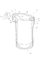
本発明に係る液状物充填包装構造体1は、図1に一実施形態として示すように、軟質のフレキシブルな包装袋2内に液状または粘稠状の被包装物を充填した液状物充填包装体3と、該包装体3を収納保持するための外容器4とから構成される。
Embodiments of the present invention will be described below based on the drawings.
As shown in FIG. 1 as an embodiment, a liquid-filled packaging structure 1 according to the present invention is a liquid-filled package in which a soft or
外容器4としては、非自立形の液状物充填包装体3を収納し、自立性および定型性を付与ための筒状の容器、例えば、図1に示すような自立用底部4aを有する、積層プラスチックフィルムからなるフレキシブル包装袋(スタンディングパウチ)が好適に用いられる。
なお、この外容器4は上記プラスチックフィルムの他、可撓性の素材、例えば紙、石灰石(炭酸カルシウム量50%超)とプラスチックの複合素材、金属等により形成することができる。
As the
In addition to the plastic film, the
なお、液状物充填包装体3は、外容器4内に収納された後、図では包装袋本体2aの両側縁上部位置において、例えば包装袋本体2aの外表面と外容器4の内表面とを相互に融着接合(シール部12)することで外容器4内にしっかりと固定されることになる。
In addition, after the liquid-filled
液状物充填包装体3は、ベースフィルム層とシーラント層とを具える積層プラスチックフィルムからなる包装袋本体と、図1では該包装袋本体の上縁部に斜め上向きに突設させたフィルム状注出ノズル5とからなる包装袋2内に、例えば、被包装物を液中シール充填により抜気した状態で密封充填したり、被包装物中に窒素等のガスを拡散させた状態で充填包装すること等により形成される。
The liquid-filled
フィルム状注出ノズル5は、セルフシール逆止機能を有することが好ましく、これにより包装袋2内の被包装物が、注出前はもちろん注出中および注出後のいずれにおいても外気との接触から十分に保護されることになり、袋内の被包装物の酸化、汚損等を有効に防止することができる。
The film-like pouring
なお、セルフシール逆止機能とは、液状物充填包装体3からの被包装物の注出に当たって、フィルム状注出ノズル5の先端部分を開口6させた状態で、液状物充填包装体3を傾動させ、これによって、被包装物の水頭圧等により注出ノズル5の注出通路8の内表面どうしを大きく離隔させて、先端開口6を開放させて被包装物の所要に応じた注出を行う。この時、包装袋本体2aが、被包装物の注出体積に応じて収縮ないしは潰れ変形するため、液状物充填包装体3内に外気を取り込むことなくその注出を行うことができる。
The self-seal check function means that the liquid-filled
この一方で、被包装物の注出を停止するときは、液状物充填包装体3を起立復帰させ、その起立復帰と同時に、注出通路8が、被包装物の水頭圧等から開放されるとともに、被包装物の包装袋本体2a内への戻流による負圧の発生下で、元形状に復帰することに加え、その被包装物の薄膜の介在によって濡れた内表面どうしを、包装袋本体2a内の減圧雰囲気のアシスト下で負圧吸着させて注出通路8を自動的に密閉封止させる機能である。
On the other hand, when stopping the dispensing of the article to be packaged, the liquid-filled
フィルム状注出ノズル5は、図1では包装袋本体2aの上端部から斜め上向きに突出して設けられているが、本発明はこれに限定されるものではなく、フィルム状注出ノズル5を包装袋本体2aの側縁上部から側方に向かって突出して設けてもよい。
Although the film-like dispensing
外容器4は、収納した液状物充填包装体3のフィルム状注出ノズル5に対応する位置に張り出し小袋部7を有し、該張り出し小袋部7内にフィルム状注出ノズル5の先端部分が格納されることになる。使用に際しては、この張り出し小袋部7を引裂き誘導疵9に沿って切り取ることで、内側に位置するフィルム状注出ノズル5の少なくとも先端部分を外部に露出させることができる。
The
本発明では、フィルム状注出ノズル5の開口予定位置よりも先端側の外表面の少なくとも一部分が、張り出し小袋部7の内表面側のシーラント層に融着(融着部11)されている点に特徴がある。このような構成とすることにより、図1に矢印で示す方向に張り出し小袋部7を引張り、引裂き誘導疵9に沿って張り出し小袋部7を切り取ると、融着部11を介してフィルム状注出ノズル5の先端部がともに引っ張られて、フィルム状注出ノズル5の先端部が引裂かれて開封されることになる。
In the present invention, at least a part of the outer surface on the tip side of the planned opening position of the film-like pouring
このときフィルム状注出ノズル5の先端部分は、張り出し小袋部7の引裂き誘導疵9に沿った切り取りに伴って一緒に、瞬時に切り取られることになるため、従来の手指等によって引裂き開封する場合に比べて、フィルム状注出ノズル5の開口端における包装用フィルムの伸びが抑制されて毛羽立ちの発生が少なくなり、液だれの発生を有効に防止することができる。
また、フィルム状注出ノズル5の開封に際し、フィルム状注出ノズル5の先端部分を手指等によって触れる必要がなく、該フィルム状注出ノズル5の衛生性および安全性を担保することができる。
At this time, the tip portion of the film-like pouring
Further, when opening the film-
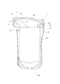
図2は、引裂き誘導疵9の他の一実施形態であり、外容器4の張り出し小袋部7とは反対側の側縁上部に設けた引裂きノッチ10を始点とし、外容器4の上縁シール部4a上を通って、張り出し小袋部7の上部から下端まで設けられている。
FIG. 2 shows another embodiment of the
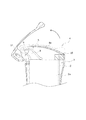
この引裂き誘導疵9に沿った引裂きは、まず引裂きノッチ10部分を両手指で把持し、図3の拡大図に矢印で示したように引裂きノッチ10を始点として上部を上向きに引っ張ることにより、該引裂き誘導疵9に沿って、その引裂きを張り出し小袋部7の下端まで一気に伝播させる。
The tearing along the
この引裂き誘導疵9によれば、始点が引裂きノッチ10位置になるため、外容器4を引裂き開封する際に、従来のようにフィルム状注出ノズル5が位置する張り出し小袋部7部分を把持等する必要がなく、引裂き誘導疵9に沿った引裂き時に誤ってフィルム状注出ノズル5が開封されてしまうおそれがない。
According to the
また、引裂きルートが従来よりも長いため、引裂きノッチ10からの引裂き伝播力によって、張り出し小袋部7の上部から下端まで小さな力で勢いよく引裂きを進行させることができる。上記したように、張り出し小袋部7は、引裂きノッチ10部分を把持し、外容器4の上方に向かって引っ張ることで引裂き誘導疵9に沿って切り取ることができるため、張り出し小袋部7の切り取りに伴って内側に位置するフィルム状注出ノズル5に無理な力がかかるおそれがなく、ノズル5が折れ曲がって変形したり、破損等することがない。
In addition, since the tearing route is longer than the conventional one, the tear propagation force from the
なお、引裂き誘導疵9は、積層プラスチックフィルムの幅方向へ−(マイナス)状に延在させて設けた一本の疵、ミシン目状に穿設した複数の疵、その幅方向に間隔をおいて設けた複数の小孔状の疵、あるいはレーザ光線等をもって連続的もしくは間欠的に設けた溶融痕などの、適宜の形状および数の疵にて形成することができる。このような引裂き誘導疵の、深さや長さ、その他の寸法は、積層プラスチックフィルムの厚さや構成材料などに応じて選択する。
The
本発明に係る液状物充填包装体で採用されている技術は、例示した液状物充填包装構造体だけではなく、さらには粉・粒状物の充填容器への適用や他の容器の開封手段としても有効である。 The technology adopted in the liquid filling and packaging body according to the present invention is not limited to the exemplified liquid filling and packaging structure, but also can be applied to filling containers of powder and granular materials and as other means for opening other containers. It is valid.
1 液状物充填包装構造体
2 包装袋
2a 包装袋本体
3 包装体
4 外容器
4a 上縁シール部
5 フィルム状注出ノズル
6 先端開口
7 張り出し小袋部
8 注出通路
9 引裂き誘導疵
10 引裂きノッチ
11 融着部
12 シール部
DESCRIPTION OF SYMBOLS 1 Liquid filling
Claims (2)
前記外容器は、前記軟質包装袋のフィルム状注出ノズル先端部に対応する部分に、引裂き誘導疵に沿って切り取り可能にかつ、該フィルム状注出ノズル先端部を露出可能に収容する張り出し小袋部を有すると共に、該張り出し小袋部の内面と、前記フィルム状注出ノズルの先端部外表面の少なくとも一部分とが融着されており、かつ、前記フィルム状注出ノズルの先端部は、前記張り出し小袋部との両者の融着部分を介して、前記引裂き誘導疵に沿った張り出し小袋部の切り取りと同時に引裂き開封可能であることを特徴とする液状物充填包装構造体。 Filled with a liquid or viscous material to be packed in a soft packaging bag with a film-like pouring nozzle projecting from the upper edge or upper side edge of a laminated bag body made of laminated film In a liquid filling and packaging structure comprising a packaging and an outer container for storing and holding the liquid filling and packaging,
The outer container is an overhanging sachet that can be cut out along the tear guide ridge at a portion corresponding to the tip of the film-like dispensing nozzle of the flexible packaging bag and the tip of the film-like dispensing nozzle can be exposed. And the inner surface of the protruding sachet portion and at least a part of the outer surface of the distal end portion of the film-like dispensing nozzle are fused, and the distal end portion of the film-like dispensing nozzle is A liquid-filled packaging structure characterized by being capable of tearing and opening simultaneously with the cutting of the overhanging sachet portion along the tear-inducing fold through the fused portion between the sachet portion and the sachet portion.
Priority Applications (1)
| Application Number | Priority Date | Filing Date | Title |
|---|---|---|---|
| JP2016085037A JP6535927B2 (en) | 2016-04-21 | 2016-04-21 | Liquid filling and packaging structure |
Applications Claiming Priority (1)
| Application Number | Priority Date | Filing Date | Title |
|---|---|---|---|
| JP2016085037A JP6535927B2 (en) | 2016-04-21 | 2016-04-21 | Liquid filling and packaging structure |
Publications (3)
| Publication Number | Publication Date |
|---|---|
| JP2017193360A true JP2017193360A (en) | 2017-10-26 |
| JP2017193360A5 JP2017193360A5 (en) | 2018-04-19 |
| JP6535927B2 JP6535927B2 (en) | 2019-07-03 |
Family
ID=60154446
Family Applications (1)
| Application Number | Title | Priority Date | Filing Date |
|---|---|---|---|
| JP2016085037A Expired - Fee Related JP6535927B2 (en) | 2016-04-21 | 2016-04-21 | Liquid filling and packaging structure |
Country Status (1)
| Country | Link |
|---|---|
| JP (1) | JP6535927B2 (en) |
Citations (5)
| Publication number | Priority date | Publication date | Assignee | Title |
|---|---|---|---|---|
| JPS476690Y1 (en) * | 1968-02-29 | 1972-03-09 | ||
| JPS61113262U (en) * | 1984-12-28 | 1986-07-17 | ||
| JP2007269329A (en) * | 2006-03-30 | 2007-10-18 | Hayashikane Sangyo Kk | Packaging bag |
| JP2010159087A (en) * | 2008-12-09 | 2010-07-22 | Yushin:Kk | Double pack packaging bag for drinking water and packaging structure co-filled with drinking water and extraction element |
| JP2015048146A (en) * | 2013-09-04 | 2015-03-16 | 大日本印刷株式会社 | Double bag |
-
2016
- 2016-04-21 JP JP2016085037A patent/JP6535927B2/en not_active Expired - Fee Related
Patent Citations (5)
| Publication number | Priority date | Publication date | Assignee | Title |
|---|---|---|---|---|
| JPS476690Y1 (en) * | 1968-02-29 | 1972-03-09 | ||
| JPS61113262U (en) * | 1984-12-28 | 1986-07-17 | ||
| JP2007269329A (en) * | 2006-03-30 | 2007-10-18 | Hayashikane Sangyo Kk | Packaging bag |
| JP2010159087A (en) * | 2008-12-09 | 2010-07-22 | Yushin:Kk | Double pack packaging bag for drinking water and packaging structure co-filled with drinking water and extraction element |
| JP2015048146A (en) * | 2013-09-04 | 2015-03-16 | 大日本印刷株式会社 | Double bag |
Also Published As
| Publication number | Publication date |
|---|---|
| JP6535927B2 (en) | 2019-07-03 |
Similar Documents
| Publication | Publication Date | Title |
|---|---|---|
| JP4996815B2 (en) | Liquid pouring nozzle, packaging bag using the same, and method of using the packaging bag | |
| JP6108517B2 (en) | Packaging bag | |
| JP2008522912A (en) | Packaging | |
| KR100994113B1 (en) | Liquid sealed bags with fully-sealed beverage or spout tubes. | |
| JP5975452B2 (en) | Packaging bag | |
| JP2012081983A (en) | Packaging bag, method for manufacturing the same, and method for filling and packaging material to be packaged to the packaging bag | |
| JP4617866B2 (en) | Branch type standing pouch | |
| JP5876643B2 (en) | Refillable packaging pouch with spout | |
| JP6044894B2 (en) | Package outer container | |
| JP5988257B2 (en) | Drip-type packaging body and drip-type packaging structure | |
| JP2004196364A (en) | Packaging structure | |
| WO2018083980A1 (en) | Spouted pouch | |
| JP2017193360A (en) | Liquid material filling and packing structure | |
| JP5090512B2 (en) | Liquid pouring nozzle, packaging bag using the same, and method of using the packaging bag | |
| JP2017178333A (en) | Injection passage structure of film-like injection nozzle | |
| JP2018039559A (en) | Packaging bag | |
| JP4246760B2 (en) | Liquid packaging bag | |
| JP2012111502A (en) | Resealable unsealing device for paper container | |
| JP4152417B2 (en) | Packaging bag | |
| JP5261904B2 (en) | Universal design pouch | |
| KR20180121610A (en) | A resealable opening device and package including an opening device | |
| JP2008105697A (en) | Universal design pouch | |
| JP2008105693A (en) | Packaging box, and package structure using it | |
| JP6126411B2 (en) | Packaging bag | |
| JP5326083B2 (en) | Liquid packaging structure |
Legal Events
| Date | Code | Title | Description |
|---|---|---|---|
| A521 | Request for written amendment filed |
Free format text: JAPANESE INTERMEDIATE CODE: A523 Effective date: 20180309 |
|
| A621 | Written request for application examination |
Free format text: JAPANESE INTERMEDIATE CODE: A621 Effective date: 20180309 |
|
| A977 | Report on retrieval |
Free format text: JAPANESE INTERMEDIATE CODE: A971007 Effective date: 20181212 |
|
| A131 | Notification of reasons for refusal |
Free format text: JAPANESE INTERMEDIATE CODE: A131 Effective date: 20181219 |
|
| A521 | Request for written amendment filed |
Free format text: JAPANESE INTERMEDIATE CODE: A523 Effective date: 20190125 |
|
| TRDD | Decision of grant or rejection written | ||
| A01 | Written decision to grant a patent or to grant a registration (utility model) |
Free format text: JAPANESE INTERMEDIATE CODE: A01 Effective date: 20190424 |
|
| A61 | First payment of annual fees (during grant procedure) |
Free format text: JAPANESE INTERMEDIATE CODE: A61 Effective date: 20190514 |
|
| R150 | Certificate of patent or registration of utility model |
Ref document number: 6535927 Country of ref document: JP Free format text: JAPANESE INTERMEDIATE CODE: R150 |
|
| R250 | Receipt of annual fees |
Free format text: JAPANESE INTERMEDIATE CODE: R250 |
|
| LAPS | Cancellation because of no payment of annual fees |