JP2017193365A - Carbonated beverage dispenser - Google Patents
Carbonated beverage dispenser Download PDFInfo
- Publication number
- JP2017193365A JP2017193365A JP2016085858A JP2016085858A JP2017193365A JP 2017193365 A JP2017193365 A JP 2017193365A JP 2016085858 A JP2016085858 A JP 2016085858A JP 2016085858 A JP2016085858 A JP 2016085858A JP 2017193365 A JP2017193365 A JP 2017193365A
- Authority
- JP
- Japan
- Prior art keywords
- flow
- carbonated water
- flow rate
- carbonated
- conical
- Prior art date
- Legal status (The legal status is an assumption and is not a legal conclusion. Google has not performed a legal analysis and makes no representation as to the accuracy of the status listed.)
- Granted
Links
Images


Landscapes
- Devices For Dispensing Beverages (AREA)
- Lift Valve (AREA)
- Sliding Valves (AREA)
- Float Valves (AREA)
Abstract
【課題】強炭酸の炭酸飲料を注出する場合に炭酸水の流量を十分に減少して、溶け込んだ炭酸ガスの放出を極力抑え、また、流量を増加する場合でも、流量調整部材が不用意に脱落することがない炭酸飲料の注出装置を提供する。【解決手段】炭酸水の流路と飲料原液の流路とを独立して有し、その流路途中で少なくとも炭酸水の流量を調整可能としたフローコントロールベースと、前記炭酸水と前記飲料原液の各流路の出口を同時に開閉可能な開閉弁と、該開閉弁を開閉操作する操作レバーとを備え、前記フローコントロールベースから供給される所定流量の前記炭酸水と前記飲料原液とを混合して炭酸飲料を注出する装置であって、前記フローコントロールベースには、一端が開口して前記炭酸水の流路と直交する有底の円錐孔を設けると共に、先端側に前記円錐孔とテーパ角が一致する円錐弁体を有して、該円錐弁体を前記開口を介して前記円錐孔に出入可能な流量調整弁を設けた。【選択図】図5[PROBLEMS] To sufficiently reduce the flow rate of carbonated water when pouring a strong carbonated carbonated beverage, to suppress the release of dissolved carbon dioxide as much as possible, and even when increasing the flow rate, the flow rate adjusting member is not prepared Disclosed is a carbonated beverage dispensing device that does not fall off. A flow control base having a carbonated water flow path and a beverage stock solution flow path independently, and capable of adjusting at least the flow rate of carbonated water in the middle of the flow path, the carbonated water and the beverage stock solution. An opening / closing valve capable of simultaneously opening and closing the outlets of the flow paths, and an operation lever for opening / closing the opening / closing valve, and mixing the carbonated water and the beverage stock solution at a predetermined flow rate supplied from the flow control base. The flow control base is provided with a bottomed conical hole that is open at one end and orthogonal to the flow path of the carbonated water, and has a conical hole and a taper on the tip side. A flow rate adjusting valve having a conical valve body having the same angle and capable of entering and exiting the conical valve body through the opening into the conical hole is provided. [Selection] Figure 5
Description
この発明は、炭酸水と飲料原液を混合して炭酸飲料を注出する装置に係り、炭酸濃度に応じた流量にて炭酸水を飲料原液と混合することができるように、炭酸水の流量調整機構を改良した構成に関する。 The present invention relates to an apparatus for dispensing carbonated water by mixing carbonated water and a beverage stock solution, and adjusting the flow rate of carbonated water so that the carbonated water can be mixed with the beverage stock solution at a flow rate according to the carbonate concentration. The present invention relates to an improved structure.
飲食店などで使用される炭酸飲料サーバーは、炭酸水を生成するカーボネータタンクと、ウイスキーや焼酎、あるいはジュース(シロップ)等、所望の飲料原液が入った原液タンクと、これら各タンクから供給される炭酸水と飲料原液とを混合して、炭酸飲料としてグラス等に注出する注出装置とから構成される。 Carbonated beverage servers used in restaurants and the like are supplied from a carbonator tank that generates carbonated water, a stock solution tank containing a desired beverage stock solution such as whiskey, shochu, or juice (syrup). And a pouring device that mixes the carbonated water with the beverage stock solution and pours it into a glass or the like as a carbonated beverage.
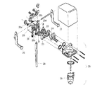
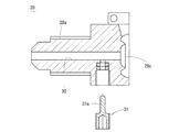
従来、炭酸飲料の注出装置としては、図12に示すものが公知である(非特許文献1)。同図に示す装置において、本発明に関係する構成を簡略的に説明すると、同装置は、カーボネータタンクと原液タンクとが接続される継手20a・20bを有し、出口となる供給口20c・20dとの間の流路で炭酸水と飲料原液それぞれの流量を別個独立に調整可能なフローコントロールベース20と、該ベース20の供給口20c・20dを開閉するバルブ21・22と、該バルブ21・22を介して前記供給口20a・20bに取り付けるオリフィスキャップ23・24と、該オリフィスキャップ22・24の二次側に取り付ける混合機構25とを備える。バルブ21・22は、各開閉レバー26・27によって別個に開閉操作される他、主レバー28を操作すれば同時に開閉できるようになっている。
Conventionally, what is shown in FIG. 12 is well-known as a carbonated drink extraction apparatus (nonpatent literature 1). In the apparatus shown in the figure, the configuration related to the present invention will be briefly described. The apparatus includes
そして、通常は、主レバー28にグラス等の容器を押しててバルブ21・22を同時に開き、フローコントロールベース20にて調整された流量の炭酸水と飲料原液がオリフィスキャップ23・24を通じて混合機構25にて混合され、ノズル29から炭酸飲料が注出される。
Normally, a container such as glass is pushed onto the
ところで、カーボネータタンクでは炭酸水の炭酸濃度の調整が可能で、強炭酸の炭酸飲料を提供する場合、カーボネータタンクへの炭酸ガスの印加圧力を高くして、強炭酸の炭酸水を生成し、これを図12に示した注出装置に供給する。 By the way, in the carbonate tank, the carbonate concentration of carbonated water can be adjusted. When providing carbonated beverages of strong carbonate, the carbonated water of strong carbonate is generated by increasing the pressure of carbon dioxide gas applied to the carbonate tank. This is supplied to the dispensing device shown in FIG.
しかし、このようにしてカーボネータタンク内の圧力が高まると、これを受けたフローコントロールベース20から勢いよく炭酸水が混合機構25に向かって放出され、炭酸飲料の注出前に、せっかく溶け込んだ炭酸ガスが装置内部で抜けてしまったり、炭酸飲料をグラス等に注出する際、フォーミング現象が起きて必要以上に泡立ってしまうという問題がある。
However, when the pressure in the carbonator tank is increased in this way, carbonated water is vigorously discharged from the
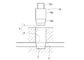
そこで、図12に示した注出装置では、強炭酸の炭酸水が供給される場合は、その流量(流速)を抑えるために、図13に示したように、フローコントロールベース20の下面から内部流路30に対してピン状の弁体31を垂直にねじ込み、当該弁体31を締め込んだり、緩めたりして上下動させて、流路30内におけるピン31aの突出量を調整することによって、この部分の流路30の開度を調整し、もって、炭酸水の流量を調整していた。なお、飲料原液側も同様の流量調整機構を有している。
Therefore, in the pouring device shown in FIG. 12, when carbonated water of strong carbonic acid is supplied, in order to suppress the flow rate (flow velocity), as shown in FIG. By adjusting the amount of protrusion of the
”マニュアルミキシングバルブ”、[online]、早川産機株式会社、[平成27年11月20日検索]、インターネット〈URL:http://www.hayakawa-sanki.co.jp/products/?id=1338290677-758575〉 “Manual Mixing Valve”, [online], Hayakawa Sangyo Co., Ltd. [searched on November 20, 2015], Internet <URL: http://www.hayakawa-sanki.co.jp/products/?id= 1338290677-758575>
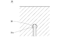
図13に示すフローコントロールベース20に採用の流量調整機構は、ストレートな流路30に対して、これよりも直径が小さいストレートなピン31aを挿入しているだけである。したがって、ピン31aの上下によって調整できる流量の増減幅が小さい。つまり、弁体31を完全に締め込んで、流路30内でのピン31aの突出量を最大とし、最も炭酸水の流量を減少させたとしても、図14に示したように、流路30内におけるピン31aの突出部分の左右には必ず隙間が生じ、強炭酸の炭酸水が不用意に発泡しない程度にその流量を十分に減少させることができない場合があった。
The flow rate adjusting mechanism employed in the
この状態から流量を増加する場合は、弁体31を緩めてピン31aの突出量を小さくするが、このときピン31aの上方に新たな隙間が確保されるだけであり、流量を大幅に増加させるものではない。さらに、この増加操作ではフローコントロールベース20に対する弁体31のねじ込み量が小さくなり、過度に緩めると炭酸水の圧力によって弁体31が抜け出てしまう恐れもあった。
When the flow rate is increased from this state, the
本発明は上述した課題を解決するためになされたもので、その目的とするところは、強炭酸の炭酸飲料を注出する場合に炭酸水の流量を十分に減少して、溶け込んだ炭酸ガスの放出を極力抑え、また、流量を増加する場合でも、流量調整部材が不用意に脱落することがない炭酸飲料の注出装置を提供することである。 The present invention has been made in order to solve the above-mentioned problems, and its object is to sufficiently reduce the flow rate of carbonated water when pouring a strong carbonated carbonated beverage, and to dissolve dissolved carbon dioxide gas. An object of the present invention is to provide a carbonated beverage pouring device in which discharge is suppressed as much as possible and the flow rate adjusting member is not accidentally dropped even when the flow rate is increased.
上述した目的を達成するために本発明では、炭酸水の流路と飲料原液の流路とを独立して有し、前記流路途中で少なくとも前記炭酸水側の流量を調整可能としたフローコントロールベースと、前記炭酸水と前記飲料原液の各流路の出口を同時に開閉可能な開閉弁と、該開閉弁を開閉操作する操作レバーとを備え、前記フローコントロールベースから供給される所定流量の前記炭酸水と前記飲料原液とを混合して炭酸飲料を注出する装置であって、前記フローコントロールベースには、一端が開口して前記炭酸水の流路と直交する有底の円錐孔を設けると共に、先端側に前記円錐孔に対応したテーパ角を有する円錐弁体を備え、該円錐弁体が前記開口を介して前記円錐孔に出入可能な流量調整弁を設けるという手段を用いた。 In order to achieve the above-described object, in the present invention, a flow control having a carbonated water flow channel and a beverage stock solution flow channel independently, and at least adjusting the flow rate on the carbonated water side in the middle of the flow channel. A base, an on-off valve capable of simultaneously opening and closing outlets of the carbonated water and the beverage stock solution, and an operating lever for opening and closing the on-off valve, and having a predetermined flow rate supplied from the flow control base An apparatus for pouring carbonated water by mixing carbonated water and the beverage stock solution, wherein the flow control base is provided with a bottomed conical hole that is open at one end and orthogonal to the carbonated water flow path. In addition, a means is provided in which a conical valve body having a taper angle corresponding to the conical hole is provided on the distal end side, and a flow rate adjusting valve that allows the conical valve body to enter and exit the conical hole through the opening is used.
この手段によれば、流量調整弁の円錐弁体が完全に円錐孔に嵌入した状態では炭酸水の流路が閉塞され、この状態から円錐弁体を変位させることによって、その外周面と円錐孔の内周面との間の隙間が徐々に拡大して、該隙間の大きさに見合った流量とすることができる。この隙間は円錐弁体を円錐孔に嵌入に近い状態とすることで限りなく小さくすることができるため、炭酸水の流量を極限に抑えることができる。なお、円錐孔や円錐弁体のテーパ角をより鋭角にすれば、円錐弁体の変位量に対して前記隙間の変化量が小さくなり、流量の増減率を小さくすることができるのに対し、前記テーパ角をより鈍角にすれば、円錐弁体の変位量に対して前記隙間の変化量も大きくなり、流量の増減率を大きくすることができる。 According to this means, when the conical valve body of the flow rate adjusting valve is completely fitted into the conical hole, the carbonated water flow path is closed, and by displacing the conical valve body from this state, the outer peripheral surface and the conical hole are The gap between the inner peripheral surface of the first and second inner surfaces gradually increases, and a flow rate corresponding to the size of the gap can be obtained. Since this gap can be made as small as possible by making the conical valve body close to being fitted into the conical hole, the flow rate of carbonated water can be minimized. In addition, if the taper angle of the conical hole or the conical valve body is made an acute angle, the change amount of the gap is small with respect to the displacement amount of the conical valve body, and the rate of increase or decrease of the flow rate can be reduced. If the taper angle is made more obtuse, the amount of change in the gap also increases with respect to the amount of displacement of the conical valve body, and the rate of increase or decrease in flow rate can be increased.
流量調整弁は円錐弁体の基端側を袋ナットによりフローコントロールベースに接続することが好ましい。円錐弁体を袋ナットの締め込みによって変位させることができ、また、流量増加方向に円錐弁体を極限に変位させたとしても袋ナットによって円錐弁体が圧力によって不用意に脱落することを防止できるからである。 The flow regulating valve is preferably connected to the flow control base at the base end side of the conical valve body by a cap nut. The conical valve body can be displaced by tightening the cap nut, and even if the conical valve body is displaced extremely in the direction of increasing the flow rate, the cap nut prevents the conical valve body from being accidentally dropped due to pressure. Because it can.
さらに、フローコントロールベースには炭酸水の流路を水平方向に設けると共に、円錐孔は底を下側として上下方向に設けることが好ましい。フローコントロールベースに対する炭酸水の供給源の接続と、円錐弁体の変位操作とが容易となり、また、円錐弁体の取り付けも容易だからである。 Further, it is preferable that the flow control base is provided with a carbonated water flow path in the horizontal direction, and the conical hole is provided in the vertical direction with the bottom at the bottom. This is because the connection of the carbonated water supply source to the flow control base and the operation of displacing the conical valve body are facilitated, and the conical valve body can be easily attached.
さらにまた、飲料原液の流路にも、炭酸水の流路と同じ円錐孔及び流量調整弁を設けることが好ましい。飲料原液についても炭酸水と同様の流量調整が可能となり、また、最初に炭酸水と飲料原液の供給源と接続する際に、いずれを炭酸水とするか飲料原液とするかの区別なく接続することができるからである。 Furthermore, it is preferable to provide the same conical hole and flow rate adjusting valve as the flow path of carbonated water in the flow path of the beverage stock solution. It is possible to adjust the flow rate of beverage stock solution in the same way as carbonated water, and when connecting to the source of carbonated water and beverage stock solution for the first time, connect regardless of which is carbonated water or beverage stock solution. Because it can.
本発明によれば、炭酸水の流路について、該流路に直交して円錐孔を設けると共に、この円錐孔に嵌入可能な円錐弁体によって流量調整弁を構成したので、円錐弁体を限りなく円錐孔に嵌入に近い状態とすることで、炭酸水の流量を極限に小さくでき、カーボネータタンクから高圧の状態で強炭酸の炭酸水が供給される場合でも、その流量(流速)を抑えることによって溶解した炭酸ガスが抜けてしまうことを防止し、強炭酸の炭酸飲料を注出することができる。 According to the present invention, the carbonated water flow path is provided with a conical hole perpendicular to the flow path, and the flow regulating valve is configured by the conical valve body that can be fitted into the conical hole. The flow rate of carbonated water can be made extremely small by making it close to the conical hole, and even when strong carbonated carbonated water is supplied from the carbonator tank at a high pressure, the flow rate (flow velocity) is suppressed. Therefore, it is possible to prevent the dissolved carbon dioxide gas from escaping and to pour out a strong carbonated carbonated beverage.
また、円錐弁体を袋ナットによってフローコントロールベースに接続したので、円錐弁体を流量増加方向に変位させたとしても、袋ナットにより円錐弁体がフローコントロールベースから脱落することを防止することができる。 In addition, since the conical valve body is connected to the flow control base by the cap nut, even if the conical valve body is displaced in the direction of increasing the flow rate, the cap nut can prevent the conical valve body from falling off the flow control base. it can.
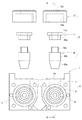
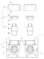
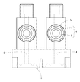
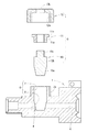
以下、本発明の好ましい実施の形態を添付した図面に従って説明する。図1は本発明の一実施形態に係る炭酸飲料の注出装置について、フローコントロールベースを分解した正面図を示したものであり、図2は背面図、図3は平面図、図4は側面図、図5はA−A線断面図をそれぞれ示している。 Hereinafter, preferred embodiments of the present invention will be described with reference to the accompanying drawings. 1 is a front view of a carbonated beverage dispensing apparatus according to an embodiment of the present invention, in which a flow control base is disassembled, FIG. 2 is a rear view, FIG. 3 is a plan view, and FIG. FIG. 5 and FIG. 5 show sectional views taken along line AA.
これらの図において、1はベース本体、2・3は炭酸水と飲料原液の供給源に接続する継手部であり、継手部2・3からベース本体1の前面にかけては炭酸水と飲料原液の流路4・5がそれぞれ独立して水平に設けられている。このようなフローコントロールベースにおいて、流路4・5の出口(二次側開口)を同時に開閉する開閉弁や、該開閉弁を開閉操作する操作レバー、及びフローコントロールベースから供給される所定流量の炭酸水と飲料原液を混合する機構は従来装置と同じ構成を採用することができるため、詳細を割愛する。
In these drawings, 1 is a base body, 2 and 3 are joint portions connected to a supply source of carbonated water and beverage stock solution, and the flow of carbonated water and beverage stock solution from the
また、流路4・5の何れを炭酸水の流路とするか飲料原液の流路とするか自由に選択でき、また、後述する流量調整機構についても同じ構成を有しているため、ここでは図5のA−A線断面図に示された流路4を炭酸水の流路と仮定して説明する。
In addition, any of the
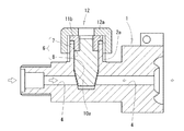
即ち、流量調整機構として、流路4を設けた継手部2の上面には雄ネジ部2aが上方に垂直に突設され、該雄ネジ部2aの上端から流路4にかけて有底の弁体挿入孔6が形成されている。この弁体挿入孔6は、流路4の上部までに設けた内径が全範囲均一な直線孔7と、この直線孔7の下端から流路4を貫通して設けた円錐孔8とからなる。
That is, as a flow rate adjusting mechanism, a male threaded
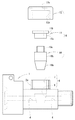
一方、9は弁体挿入孔6に装着する流量調整弁であって、弁体10と、パッキン11と、前記雄ネジ部2aに螺合する袋ナット12とからなる。
On the other hand, 9 is a flow rate adjusting valve mounted in the valve
弁体10は、先端側(下端側)に円錐孔8の内周面とテーパ角が一致する外周面からなる円錐部10aを有し、これを直線孔7をガイド孔として上下にスライドする直線軸部10bと一体に形成すると共に、基端側(上端側)には前記パッキン11と螺合する雄ネジ軸部10cを設けている。
The
パッキン11は、弁体10の直線軸部10bと同径の取付部11aの上部に、継手部2の雄ネジ部2aとほぼ同径の拡径部11bを設けた二段構成であり、上下に前記雄ネジ軸部10cが螺合する雌ネジ孔11cを貫設している。
The packing 11 has a two-stage configuration in which an
袋ナット12は、雄ネジ部2aに螺合する雌ネジ部12aを有し、その上面には通孔12bを設けている。
The
上記構成の流量調整弁9は、まず弁体10とパッキン11を一体化した状態で、円錐部10aを下向きにして弁体挿入孔6に挿入し、袋ナット12を雄ネジ部2aに螺合することで装着が完了する。ここで、フローコントロールベースに炭酸水の供給源(カーボネータタンク)を接続する前は、弁体10は自由落下によって弁体挿入孔6に落とし込まれた状態にあるが、前記供給源を接続して流路4が炭酸水によって充満すると、袋ナット12を緩めた状態では、浮力または/及び炭酸水の圧力によって、パッキン11が袋ナット12に密着する位置まで浮き上がろうとする。そして、流路4が炭酸水で充満しているときの弁体10の浮き上がり量は、袋ナット12の締め込み具合(緩め具合)によって調整される。
The flow
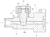
即ち、袋ナット12を完全に締め込んだ状態では弁体10の浮き上がり量はゼロとなり、図6に示したように、円錐部10aが円錐孔8に嵌入した状態となる。この状態では、円錐部10aの外周面全部が円錐孔8の内周面全部に密着して流路4を閉塞(寸断)するため、炭酸飲料の注出は不可となる。
That is, when the
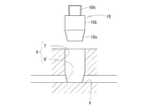
一方、袋ナット12を緩めると弁体10が浮き上がり、図7〜9に示したように、円錐部10aの外周面と円錐孔8の内周面の間に隙間が生じる。袋ナット12の緩め方が大きいほど、この隙間は大きくなる。また、円錐部10aの端部と円錐孔8の底との間の隙間も大きくなる。したがって、これら隙間の大きさに応じた流量の炭酸水がフローコントロールベースの二次側に供給されることになる。
On the other hand, when the
ここで、袋ナット12を完全に締め込んだ状態から僅かに緩めただけで、図7に示すように、円錐部10aが円錐孔8から浮き上がって、円錐孔8の内周面に形成される流路4の開口部4a・4bが開通するが、上述のように、弁体10の円錐部10aと円錐孔8との間の隙間は極めて小さく、ここを流れる炭酸水の流量を極限に抑えることができる。
Here, when the
一方、袋ナット12を緩めていけば弁体10の浮き上がり量が大きなり、流量を増加することができるが、最も袋ナット10を緩めた図9の全開状態としても、弁体10は袋ナット12に内蔵されているため、弁体挿入孔6から飛び出すには至らず、漏水することもない。
On the other hand, if the
なお、上記実施形態では、流路4の下部に至るまで円錐孔8を設けたが、図10に示すように、流路4の下点に底が位置するように円錐孔8’を設けてもよく、また、図11に示すように、流路4の下点より下部側は小径の直線孔7’としてもよく、弁体10についても、これら円錐孔8’や直線孔7’に対応した形状とすることも本発明に含まれる。
In the above embodiment, the
さらに、円錐孔8や円錐部10aのテーパ角は図示したものに限らず、より鋭角にすることも、より鈍角にすることもある。
Further, the taper angles of the
さらにまた、弁体挿入孔6や流量調整弁の向きは上から下に向かうものに限らず、流路4に直交する方向であれば、左右または下から上に向かう方向に構成することも可能である。
Furthermore, the direction of the valve
また、他方の流路5については説明を省略したが、流路4と同様の上記流量調整機構を設けることも可能である他、仮に、飲料原液の流路5で固定するならば、当該流路5については従来装置と同じ流量調整機構とし、流路4のみに本発明の流量調整機構を設けることも可能である。
The description of the
1 ベース本体
2・3 継手部
2a 雄ネジ部
4・5 流路
6 弁体挿入孔
7 直線孔
8 円錐孔
9 流量調整弁
10 弁体
10a 円錐部
10b 直線軸部
10c 雄ネジ軸部
11 パッキン
11a 取付部
11b 拡径部
11c 雌ネジ孔
12 袋ナット
12a 雌ネジ部
12b 通孔
DESCRIPTION OF
Claims (4)
Priority Applications (1)
| Application Number | Priority Date | Filing Date | Title |
|---|---|---|---|
| JP2016085858A JP6636382B2 (en) | 2016-04-22 | 2016-04-22 | Carbonated beverage dispenser |
Applications Claiming Priority (1)
| Application Number | Priority Date | Filing Date | Title |
|---|---|---|---|
| JP2016085858A JP6636382B2 (en) | 2016-04-22 | 2016-04-22 | Carbonated beverage dispenser |
Publications (2)
| Publication Number | Publication Date |
|---|---|
| JP2017193365A true JP2017193365A (en) | 2017-10-26 |
| JP6636382B2 JP6636382B2 (en) | 2020-01-29 |
Family
ID=60154458
Family Applications (1)
| Application Number | Title | Priority Date | Filing Date |
|---|---|---|---|
| JP2016085858A Active JP6636382B2 (en) | 2016-04-22 | 2016-04-22 | Carbonated beverage dispenser |
Country Status (1)
| Country | Link |
|---|---|
| JP (1) | JP6636382B2 (en) |
Cited By (1)
| Publication number | Priority date | Publication date | Assignee | Title |
|---|---|---|---|---|
| CN115823274A (en) * | 2022-12-16 | 2023-03-21 | 宁波英特灵气动科技有限公司 | Pneumatic throttle valve |
Citations (6)
| Publication number | Priority date | Publication date | Assignee | Title |
|---|---|---|---|---|
| JPS563330U (en) * | 1979-06-20 | 1981-01-13 | ||
| JPS6054872U (en) * | 1983-09-21 | 1985-04-17 | 前沢化成工業株式会社 | Gate valve device |
| JPS6262698U (en) * | 1985-10-07 | 1987-04-18 | ||
| JPH01146078U (en) * | 1988-03-30 | 1989-10-06 | ||
| JPH0386132U (en) * | 1989-12-25 | 1991-08-30 | ||
| JP2002106972A (en) * | 2000-09-29 | 2002-04-10 | Fujii Gokin Seisakusho Co Ltd | Joint for connection of hot water circuit |
-
2016
- 2016-04-22 JP JP2016085858A patent/JP6636382B2/en active Active
Patent Citations (6)
| Publication number | Priority date | Publication date | Assignee | Title |
|---|---|---|---|---|
| JPS563330U (en) * | 1979-06-20 | 1981-01-13 | ||
| JPS6054872U (en) * | 1983-09-21 | 1985-04-17 | 前沢化成工業株式会社 | Gate valve device |
| JPS6262698U (en) * | 1985-10-07 | 1987-04-18 | ||
| JPH01146078U (en) * | 1988-03-30 | 1989-10-06 | ||
| JPH0386132U (en) * | 1989-12-25 | 1991-08-30 | ||
| JP2002106972A (en) * | 2000-09-29 | 2002-04-10 | Fujii Gokin Seisakusho Co Ltd | Joint for connection of hot water circuit |
Cited By (2)
| Publication number | Priority date | Publication date | Assignee | Title |
|---|---|---|---|---|
| CN115823274A (en) * | 2022-12-16 | 2023-03-21 | 宁波英特灵气动科技有限公司 | Pneumatic throttle valve |
| CN115823274B (en) * | 2022-12-16 | 2024-02-20 | 宁波英特灵气动科技有限公司 | Pneumatic throttle valve |
Also Published As
| Publication number | Publication date |
|---|---|
| JP6636382B2 (en) | 2020-01-29 |
Similar Documents
| Publication | Publication Date | Title |
|---|---|---|
| EP3978424B1 (en) | Cooled beverage dispensing nozzle with in-nozzle mixing | |
| CN100509608C (en) | Beverage dispensing appartus and beverage dispensing system | |
| IE56896B1 (en) | Dispense tap | |
| EP3122685B1 (en) | High flow, reduced foam dispensing nozzle | |
| US7513398B2 (en) | Beverage dispense valve | |
| US10053351B2 (en) | Valve for dispensing a liquid and optionally aerating it | |
| JP6660463B2 (en) | Beverage dispensing device | |
| EA009232B1 (en) | Beverage dispensing tap | |
| ITRN20010019A1 (en) | PERFECTED COMPENSATOR TO REGULATE THE FLOW OF DRINKS IN DISPENSING TAPS. | |
| JP6636382B2 (en) | Carbonated beverage dispenser | |
| GB2436558A (en) | Beverage dispense valve | |
| JP6586062B2 (en) | Carbonated beverage dispenser | |
| JP6704338B2 (en) | Carbonated water cook | |
| JP7257666B2 (en) | Dispensing nozzle for post-mix carbonated beverage server | |
| JP6713228B2 (en) | Liquid pouring device | |
| ES3014280T3 (en) | Carbonated beverage dispenser | |
| JP6511335B2 (en) | Effervescent beverage automatic dispenser | |
| JP4052183B2 (en) | Beverage dispensing nozzle | |
| JP6503006B2 (en) | Carbonated beverage dispenser | |
| JP2001206491A (en) | Sparkling drink pouring cock | |
| JP2025000243A (en) | Faucet | |
| JP6994399B2 (en) | Faucet pillar | |
| JP5125603B2 (en) | Electric kettle hot water supply valve | |
| US20090121479A1 (en) | Device For Use in a Dispensing Apparatus | |
| JP2019094087A (en) | Discharge nozzle for carbonated water, and method for discharging high-concentration carbonated water |
Legal Events
| Date | Code | Title | Description |
|---|---|---|---|
| A621 | Written request for application examination |
Free format text: JAPANESE INTERMEDIATE CODE: A621 Effective date: 20180305 |
|
| A977 | Report on retrieval |
Free format text: JAPANESE INTERMEDIATE CODE: A971007 Effective date: 20190128 |
|
| A131 | Notification of reasons for refusal |
Free format text: JAPANESE INTERMEDIATE CODE: A131 Effective date: 20190205 |
|
| A521 | Request for written amendment filed |
Free format text: JAPANESE INTERMEDIATE CODE: A523 Effective date: 20190402 |
|
| A131 | Notification of reasons for refusal |
Free format text: JAPANESE INTERMEDIATE CODE: A131 Effective date: 20190611 |
|
| A521 | Request for written amendment filed |
Free format text: JAPANESE INTERMEDIATE CODE: A523 Effective date: 20190809 |
|
| TRDD | Decision of grant or rejection written | ||
| A01 | Written decision to grant a patent or to grant a registration (utility model) |
Free format text: JAPANESE INTERMEDIATE CODE: A01 Effective date: 20191203 |
|
| A61 | First payment of annual fees (during grant procedure) |
Free format text: JAPANESE INTERMEDIATE CODE: A61 Effective date: 20191218 |
|
| R150 | Certificate of patent or registration of utility model |
Ref document number: 6636382 Country of ref document: JP Free format text: JAPANESE INTERMEDIATE CODE: R150 |
|
| R250 | Receipt of annual fees |
Free format text: JAPANESE INTERMEDIATE CODE: R250 |
|
| R250 | Receipt of annual fees |
Free format text: JAPANESE INTERMEDIATE CODE: R250 |
|
| R250 | Receipt of annual fees |
Free format text: JAPANESE INTERMEDIATE CODE: R250 |