JP2017193382A - container - Google Patents
container Download PDFInfo
- Publication number
- JP2017193382A JP2017193382A JP2017152056A JP2017152056A JP2017193382A JP 2017193382 A JP2017193382 A JP 2017193382A JP 2017152056 A JP2017152056 A JP 2017152056A JP 2017152056 A JP2017152056 A JP 2017152056A JP 2017193382 A JP2017193382 A JP 2017193382A
- Authority
- JP
- Japan
- Prior art keywords
- container
- inner ring
- lid
- main body
- support wall
- Prior art date
- Legal status (The legal status is an assumption and is not a legal conclusion. Google has not performed a legal analysis and makes no representation as to the accuracy of the status listed.)
- Granted
Links
Images
Landscapes
- Closures For Containers (AREA)
Abstract
【課題】製造が容易で、気密性が長期に亘って良好に維持される容器が提供される容器を提供すること。【解決手段】本発明の容器1は、開口部21を有する容器本体2と該開口部21を閉鎖可能な蓋体3とを備え、蓋体3は、容器本体2に当接するインナーリング7を有しており、インナーリング7は、シート成形体からなり、内部に、支持壁76を有している。インナーリング7は、容器内側に向けられる面を形成する内面部72と支持壁76との間に空間S1を有するとともに、容器外側に向けられる面を形成する外面部73と支持壁76との間にも空間S2を有している。【選択図】図3To provide a container which is easy to manufacture and provides a container whose airtightness is satisfactorily maintained over a long period of time. A container 1 of the present invention includes a container body 2 having an opening 21 and a lid 3 that can close the opening 21, and the lid 3 has an inner ring 7 that contacts the container body 2. The inner ring 7 is made of a sheet molded body and has a support wall 76 inside. The inner ring 7 has a space S1 between an inner surface portion 72 that forms a surface directed toward the inner side of the container and the support wall 76, and between the outer surface portion 73 that forms a surface directed toward the outer side of the container and the support wall 76. Also has a space S2. [Selection] Figure 3
Description
本発明は、容器に関する。 The present invention relates to a container.
開口部を有する容器本体と該開口部を気密に閉鎖可能な蓋体とを備えた容器が用いられている。例えば、手や指の洗浄用の洗浄剤やメイク落とし用の洗浄剤を含浸したシート等を複数枚積層した状態で収容する液含浸シートの収容容器として、気密に閉鎖可能な蓋体を備えた容器が用いられており、容器に収容することにより、液含浸シートの湿潤状態を長期に亘って維持できる。
従来の気密に閉鎖可能な蓋体を備えた容器として、蓋体の外周縁より内側に、インナーリングと呼ばれる環状の垂下片を設け、該垂下片を容器本体の開口部内面に当接させて気密性を確保する容器が知られている。例えば、特許文献1には、蓋体に設けた垂下片と容器本体の開口部内面との密着状態が長期に亘って維持されるように工夫した容器が提案されている。
A container including a container body having an opening and a lid capable of hermetically closing the opening is used. For example, an airtightly closable lid is provided as a container for a liquid-impregnated sheet for storing a plurality of sheets impregnated with a detergent for washing hands and fingers or a detergent for removing makeup. A container is used, and the wet state of the liquid-impregnated sheet can be maintained for a long time by being accommodated in the container.
As a container having a conventional airtightly closable lid, an annular hanging piece called an inner ring is provided inside the outer periphery of the lid, and the hanging piece is brought into contact with the inner surface of the opening of the container body. Containers that ensure hermeticity are known. For example,
しかし、大きな開口部を有する広口の容器を、合成樹脂から射出成形により製造する場合、射出成形と金型の修正とを繰り返さなければ、容器本体と蓋体との間に良好な気密性が得られない場合が多く、気密性の良好な容器を得るためには、金型の寸法調整に時間と手間を要していた。
また、開口部の形状が真円でない場合、完成後の容器に充分な気密性が得られない場合があった。また、製造直後の容器に充分な気密性が得られても、時間の経過や蓋体の開閉の繰り返し等によって、容器本体と蓋体の気密性が低下する場合もあった。
However, when a wide-mouthed container having a large opening is manufactured from synthetic resin by injection molding, good airtightness can be obtained between the container body and the lid unless injection molding and mold correction are repeated. In many cases, it takes time and effort to adjust the dimensions of the mold in order to obtain a container with good airtightness.
Moreover, when the shape of the opening is not a perfect circle, sufficient airtightness may not be obtained in the completed container. Further, even when sufficient airtightness is obtained in the container immediately after manufacture, the airtightness of the container body and the lid may be lowered due to the passage of time, repeated opening / closing of the lid, or the like.
本発明の課題は、前述した従来技術が有する欠点を解消し得る容器に関する。 The subject of this invention is related with the container which can eliminate the fault which the prior art mentioned above has.
本発明は、開口部を有する容器本体と該開口部を閉鎖可能な蓋体とを備える容器であり、前記蓋体は、前記容器本体に当接するインナーリングを有しており、前記インナーリングは、シート成形体からなり、内部に空間を有している、容器を提供するものである。 The present invention is a container comprising a container body having an opening and a lid that can close the opening, the lid having an inner ring that contacts the container body, and the inner ring is The container is made of a sheet molded body and has a space inside.
また、本発明は、前記容器内に製品が収容された容器入り製品を提供するものである。
また、本発明は、前記容器の製造方法であって、インナーリングが形成されたシート成形体からなるインナーリング形成部材を前記蓋体の本体部に配置する配置工程、前記インナーリングを、前記蓋体の中央側から外方に向かって押圧して、該インナーリングの位置を調整する位置調整工程、及び位置調整後のインナーリング形成部材を、前記蓋体の本体部に固定する固定工程を具備する容器の製造方法を提供するものである。
Moreover, this invention provides the product in a container with which the product was accommodated in the said container.
The present invention is also a method for manufacturing the container, wherein the inner ring forming member made of a sheet molded body on which an inner ring is formed is disposed on the main body of the lid, and the inner ring is disposed on the lid. A position adjusting step of adjusting the position of the inner ring by pressing outward from the center side of the body, and a fixing step of fixing the inner ring forming member after the position adjustment to the main body of the lid body A method for manufacturing a container is provided.
本発明によれば、製造が容易で、気密性が長期に亘って良好に維持される容器が提供される。また、本発明の容器入り製品によれば、内部に収容された製品の好ましい状態、例えば適度な湿潤状態を長期に亘って安定に維持することができる。 ADVANTAGE OF THE INVENTION According to this invention, the container which is easy to manufacture and whose airtightness is favorably maintained over a long period of time is provided. Moreover, according to the product in a container of the present invention, a preferable state of the product accommodated in the inside, for example, an appropriate wet state, can be stably maintained over a long period of time.
以下に、本発明をその好ましい実施形態に基づいて説明する。
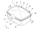
本発明の一実施形態である容器1は、図1及び図2に示すように、開口部21を有する容器本体2と該開口部21を気密に閉鎖可能な蓋体3とを備えている。
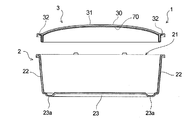
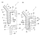
容器本体2は、図2に示すように、筒状の周壁部22と、周壁部22の下端を閉鎖する底部23とを有している。周壁部22は、その上端に開口部21を有している。また、容器本体2は、図3に示すように、周壁部22の上端近傍の内面に、後述する蓋体3のインナーリング7が密着するリング当接部6を有しており、該リング当接部6には、本体リブ61が突設されている。本体リブ61は、円弧状の断面を有し、容器本体2の周壁部22の全周に亘って形成されている。
本体リブ61の存在により、インナーリング7とリング当接部6との間の密着性が向上して、より確実に気密性が確保される。
また、開口部21の周縁部には、周壁部22から外方に向かって張り出すフランジ部24が形成されており、フランジ部24の先端には環状の垂下部25が形成されている。底部23における、周縁部よりやや内側に離間した位置には、下方に向けて凸に突出した高台部23aが形成されている。
Below, this invention is demonstrated based on the preferable embodiment.
As shown in FIGS. 1 and 2, the
As shown in FIG. 2, the
Due to the presence of the
Further, a
蓋体3は、容器本体2の開口部21を開閉自在に設けられている。
図1に示すように、本実施形態における蓋体3は、ヒンジ部4を介して容器本体2に回動可能に連結されており、蓋体3に設けた係止片5の裏面に形成された突起51が、容器本体2の垂下部25の下端に係合することにより、蓋体3による閉蓋状態が安定に維持される。他方、係止片5は、指で手前に引きつつ上方に持ち上げることで、垂下部25の下端に対する係合状態が解除され、開口部21が開口する。なお、図2には、ヒンジ部4による連結を解除し、容器本体2と蓋体3とを上下方向に分離した状態が示されている。
The
As shown in FIG. 1, the
なお、前述したヒンジ部4は、容器本体2の垂下部25から突出する一対の軸受部41,41間に、蓋体3の周縁部に延設された張り出し部42を配置し、該張り出し部42の両端に設けられた軸突起(図示せず)を軸受部41,41に設けられた穴に挿入することにより、容器本体2と蓋体3とを連結している。
Note that the hinge portion 4 described above has an
本実施形態における蓋体3は、合成樹脂の射出成型品からなる本体部30と、シート成形品からなるインナーリング形成部材70とからなる。シート成形品は、合成樹脂製のシートを、所定形状に成形したものであり、成形方法は、特に制限されるものではないが、真空成形、圧空成形、プレス成形が好ましい。合成樹脂製のシートは、単層構造のものでも2層以上の多層構造のものでも良い。また、合成樹脂製のシート又はそれに含まれる層を構成する合成樹脂の種類としては、例えば、ポリプロピレン、ポリエチレン等のポリオレフィン、ポリスチレン、ポリエチレンテレフタレート等のポリエステル、ポリアミド等が挙げられるが、合成樹脂製のシートは、合成樹脂の射出成型品からなる蓋体3の本体部30との一体化(例えば後述の超音波シールによる一体化)の観点から、蓋体3の本体部30と同材料であることが好ましい。
The
蓋体3の本体部30は、図2及び図3に示すように、上方に向けて凸の曲面状に形成された天面部31と、その周囲に形成された環状の平坦部32とを有し、平坦部32の外周部に環状の垂下部33が形成されている。また、本体部30における垂下部33から離間した内側に、内側垂下部35が形成されている。
As shown in FIGS. 2 and 3, the
インナーリング形成部材70は、図2及び図3に示すように、インナーリング7を形成する部材であり、天面部31の下面に沿って配された部分71、インナーリング7の容器内側に向けられる面を形成する内面部72、インナーリング7の容器外側に向けられる面を形成する外面部73、及び本体部30の平坦部32の下面に沿って配された部分74を有しており、内面部72から外面部73に亘る部分が、本体部30から離間してインナーリング7を形成している。
インナーリング7は、容器本体2に当接して、容器本体2と蓋体3との気密性を高めるものであり、通常、蓋体3の周縁から離間した部位に設けられ、容器本体2の開口部21又はその近傍における周壁部22の内面に当接する。
As shown in FIGS. 2 and 3, the inner
The
本実施形態の本体部30における内側垂下部35は、インナーリング7の内部に配されて支持壁76を構成している。
支持壁76は、インナーリング7が本体リブ61と密着した際の、インナーリング7の変形量を所定の範囲内に収めるものであり、変形し易いインナーリング7と比較して変形しにくくなっている。変形しにくくする為には、例えばインナーリング形成部材70の厚みよりも支持壁76の厚みを厚くする等、種々の方法を採用することができる。
また支持壁76は、蓋体3の本体部30の強度を向上させる役割も果たしている。
さらに、インナーリング7が内部に支持壁76を有することにより、落下衝撃等の応力を容器1が受けた際に、インナーリング7が大きく変形することを防止し、容器1の気密性を維持することができる。また、本体リブ61の寸法を変更して容器1の気密性を高めた際に、インナーリング7が本体リブ61と嵌合する時に発生する変形音を低減する効果も有する。
The inner hanging
The
The
Furthermore, since the
インナーリング7は、図3に示すように、内面部72と支持壁76との間に空間S1を有するとともに、外面部73と支持壁76との間にも空間S2を有しており、更に支持壁76の下端とその対向部位75との間にも空間S3を有している。また、インナーリング形成部材70は、平坦部32の下面に沿って配された部分74が、該平坦部32に融着部77において接合されており、それによって本体部30と一体化されている。融着部77は、蓋体3の周方向の全周に亘って連続して形成されていても良いし、蓋体3の周方向に間欠的に形成されていても良い。また、融着に代えて接着剤で接合されていても良い。更に、インナーリング形成部材70は、天面部31の下面に対しても融着や接着剤等によって接合されていても良い。融着の方法としては、超音波シール、高周波シール、ヒートシール等を用いることができる
As shown in FIG. 3, the
本実施形態の容器1によれば、図3に示すように、インナーリング7が、外面部73と支持壁76との間に空間S2を有し、リング当接部6に押圧されて容器の内側方向に向かって変位し易い上に、その変位状態からの復元性にも優れるため、蓋体3の本体部30や容器本体2として、寸法を高精度に制御したものを用いなくても、蓋体3と容器本体2との間に良好な気密性が得られる。そのため、本実施形態の容器1は、金型の寸法調整に時間と手間を掛けずに容易に製造することができる。
According to the
また、同様の理由により、本実施形態の容器1によれば、時間の経過や蓋体の開閉の繰り返し等を行っても、容器本体と蓋体の気密性が低下し難く、気密性が長期に亘って良好に維持される。
For the same reason, according to the
なお、インナーリング形成部材70の外面部73と支持壁76との間の空間S2は、支持壁76に直交する方向の厚みが、少なくとも0.5mm以上、好ましくは1mm以上である。また、支持壁76の下端とその対向部位75との間の距離L1は、好ましくは1mm以下、より好ましくは0.5mm以下である。
The space S2 between the
蓋体3の本体部30及び容器本体2を合成樹脂から形成する場合の合成樹脂としては、各種のプラスティック材料が用いられるが、例えば、ポリプロピレン、ポリエチレン等のポリオレフィン、ポリスチレン、ポリエチレンテレフタレート等のポリエステル、ポリアミド等が挙げられるが、これらに制限されるものではない。
Various plastic materials are used as the synthetic resin when the
本実施形態の容器1に好ましい製造方法について説明する。
先ず、容器本体2及び蓋体3の本体部30を、それぞれ、通常の射出成形により製造する。そして、例えばポリプロピレンなど合成樹脂製シートを、必要によりヒーター等で加熱した後、真空成形、圧空成形又はプレス成形等により所定形状に成形してシート成形体を得る。このシート成形体に不要な部分があればトリミングする。
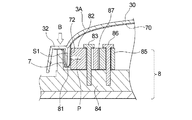
得られたシート成形体を、インナーリング形成部材70として、本体部30の内面に、図5に示すように重ねて配置する配置工程、インナーリング7の位置調整を行う位置調整工程、及びインナーリング形成部材70の固定工程を行う。
A preferable manufacturing method for the
First, the
As shown in FIG. 5, an arrangement process of placing the obtained sheet molded body as an inner
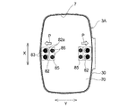
インナーリング7の位置調整工程においては、本体部30とインナーリング形成部材70とを重ねた複合体3Aを、図5に示すように、インナーリング挿入部81を形成した変形用治具8にセットする。あるいは、インナーリング形成部材70を変形用治具8にセットした後に、本体部30をインナーリング形成部材70に重ねて複合体3Aとする(配置工程)。複合体3A又はインナーリング形成部材70を変形用治具8にセットする際には、インナーリング7をインナーリング挿入部81に挿入させる。また、そのセットに先立ち、インナーリング形成部材70の内面部72を押圧させるための押圧部材82の位置を予め調整しておくことで、配置工程と位置調整工程を同時に行うことができる。押圧部材82には、長孔82aが形成されており、押圧部材82を、ボルト等の固定具83で支持台84に固定する際の固定位置を異ならせることにより、複合体3Aを変形用治具8にセットした際にインナーリング7に加わる変形力Pの大きさを適宜に調整することができる。
In the position adjustment process of the
射出成形された容器本体2及び蓋体3の本体部30と比較して、真空成形等で成形されたインナーリング形成部材70は、成形後の各寸法のばらつきが大きい。そこで、上記の押圧部材82等を使用して、インナーリング7とリング当接部6の本体リブ61との位置関係を調整し、正確に調整することが好ましい。すなわち、インナーリング形成部材70の内面部72を押圧部材82と接触、押圧させることにより、インナーリングは、蓋体の中央側から外側に向かって変形し、インナーリング7とリング当接部6の本体リブ61との位置関係を、正確に調整することができる。
The inner
従って、変形力Pの調整により、完成した容器における、インナーリング7とリング当接部6との接触状態を適宜に調整することが可能であり、そのような調整を行うことで、気密性が高く、その気密状態が安定に維持される容器を得ることができる。
なお、図中85は、ボルト等の固定具86で支持台84の特定の位置のみに固定可能な非可動部材であり、押圧部材82と非可動部材85との間に、鉄板等からなる適宜の枚数のシム87を介在させることができる。シム87の枚数を適宜に調整することによって押圧部材82の固定位置を高精度に調整することができる。
Therefore, by adjusting the deformation force P, it is possible to appropriately adjust the contact state between the
In the figure,
インナーリング形成部材70の固定工程においては、インナーリング7の位置調整工程におけるインナーリング7の変形状態を維持した状態下に、インナーリング形成部材70の所定位置を本体部30に対して固定し、そのインナーリング7の変形状態が、変形用治具から取り外しても、完全には元に戻らないようにし、少なくとも変形の一部が残るようにする。インナーリング形成部材70の本体部30に対する固定は、例えば、図5中に符号Bで示す部位に、超音波シール用のホーンを当て、インナーリング形成部材70を、超音波シールにより、本体部30の平坦部32に融着させる。
In the fixing process of the inner
このように、インナーリング7を変形させた状態で、インナーリング形成部材の固定を行うことで、射出成形と金型の修正とを繰り返さなくても、蓋体3と容器本体2との間に優れた気密性を有する容器を得ることができる。このよう調整を可能とする観点から、本体部30とインナーリング形成部材70とを重ねた複合体3Aは、インナーリングを押圧しない状態において、インナーリング形成部材70の内面部72と支持壁76との間に、支持壁76に直交する方向の厚みが、少なくとも1mm以上、好ましくは2mm以上の空間S1が生じるものであることが好ましい。
Thus, by fixing the inner ring forming member in a state where the
図4及び図5に示す例は、環状のインナーリング7を、蓋体3の回動軸に直交する方向Yに押圧、変形して、その状態でインナーリング形成部材70を蓋体3の本体部30に固定する例であったが、それに代えて、環状のインナーリング7を、蓋体3の回動軸に沿う方向Xに押圧、変形して、その状態でインナーリング形成部材70を蓋体3の本体部30に固定しても良い。更に、環状のインナーリング7を、蓋体3の回動軸に直交する方向Y及び該回動軸に沿う方向Xの両方向に押圧、変形して、その状態でインナーリング形成部材70を蓋体3の本体部30に固定しても良い。
In the example shown in FIGS. 4 and 5, the annular
本発明は、上記の実施形態に制限されず、種々の変形が可能である。
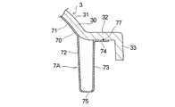
例えば、本発明における容器は、図6に示すインナーリング7Aのように、内部に支持壁76を有しないインナーリングを備えたものであっても良く、また、前述したリング当接部6の本体リブ61を有しないものであっても良い。この場合には、容器本体2の周壁部22とインナーリングが直接当接して、インナーリングが変形することにより容器本体内の気密を保つことが可能となる。
The present invention is not limited to the above-described embodiment, and various modifications can be made.
For example, the container according to the present invention may be provided with an inner ring that does not have the
また、容器内に収容する被収容物としては、各種の製品が挙げられるが、容器に収容する製品その他の被収容物は、洗浄剤を含浸したシートに限られず、洗浄剤以外の液を含浸させた液含浸シートであっても良く、シートに含浸させない、洗浄剤や食品、整髪剤等であっても良い。液含浸シートにおいて液を含浸させるシートとしては、紙、不織布、織物、編み物、又はそれらの複合体等が挙げられる。液含浸シートは、トイレに廃棄可能なように水解性を示すものであっても良いし、水解性のないものであっても良い。また、液含浸シートは、積層した複数枚を簡易な袋に入れた状態で、本発明の容器内に収容されていても良い。 In addition, various products can be listed as the items to be stored in the container, but the products and other items to be stored in the container are not limited to the sheet impregnated with the cleaning agent, but are impregnated with a liquid other than the cleaning agent. It may be a liquid-impregnated sheet, or may be a cleaning agent, food, hairdressing agent, or the like that does not impregnate the sheet. Examples of the sheet impregnated with the liquid in the liquid-impregnated sheet include paper, nonwoven fabric, woven fabric, knitted fabric, and composites thereof. The liquid-impregnated sheet may exhibit water decomposability so that it can be discarded in the toilet, or may not have water decomposability. Moreover, the liquid-impregnated sheet may be accommodated in the container of the present invention in a state where a plurality of laminated sheets are put in a simple bag.
また、容器内に収容する製品その他の被収容物は、液状物であっても良いし、クリーム状ないしペースト状であっても良いし、固体であっても良い。また、これらの2種以上を非混合状態で収容しても良いし、混合状態で収容しても良い。
また、容器入り製品において容器内に収容する製品は、上述した液含浸シートや食品の他、液を含浸させないシート、綿棒、脱脂綿等であっても良く、それ以外のものであっても良い。また、本発明の容器内に収容することにより維持される製品の好ましい状態は、適度な湿潤状態に代えて、乾燥状態、非変色状態、非酸化状態等であっても良い。
In addition, the product and other objects to be accommodated in the container may be liquid, cream or paste, or solid. Moreover, these 2 or more types may be accommodated in a non-mixed state, or may be accommodated in a mixed state.
In addition, the product contained in the container in the container-containing product may be a sheet not impregnated with liquid, a cotton swab, absorbent cotton, or the like, in addition to the liquid-impregnated sheet and food described above. Moreover, the preferable state of the product maintained by accommodating in the container of this invention may be a dry state, a non-discolored state, a non-oxidized state, etc. instead of a moderate wet state.
また、本発明の容器の製造方法においては、インナーリング形成部材を蓋体の本体部に配置する配置工程後に、インナーリングの位置調整工程を行っても良い。また、本発明の容器の製造方法において、インナーリングを、蓋体の中央側から外方に向かって押圧する部位は、蓋体の周方向における任意の1箇所又は複数箇所であっても良く、例えば、図4に示すように、蓋体3の回動軸に直交する方向Yにおける相対向する一対の部位のみであっても良いし、蓋体3の回動軸に直交する方向Y及び該回動軸と平行な方向Xのそれぞれにおける相対向する一対の部位であっても良い。更に、蓋体3の回動軸に直交する方向Yにおける相対向する一対の部位を、蓋体の中央側から外方に向かって押圧する一方、蓋体3の回動軸と平行な方向Xにおける相対向する一対の部位を、蓋体の外方から中央側に向かって押圧しても良い。
Moreover, in the manufacturing method of the container of this invention, you may perform the position adjustment process of an inner ring after the arrangement | positioning process which arrange | positions an inner ring formation member in the main-body part of a cover body. Further, in the container manufacturing method of the present invention, the portion for pressing the inner ring outward from the center side of the lid may be any one or a plurality of locations in the circumferential direction of the lid, For example, as shown in FIG. 4, only a pair of opposing portions in the direction Y orthogonal to the rotation axis of the
1 容器
2 容器本体
21 開口部
22 周壁部
3 蓋体
30 本体部
3A 複合体
6 リング当接部
61 本体リブ
7,7A インナーリング
70 インナーリング形成部材
76 支持壁
77 融着部
8 変形用治具
81 インナーリング挿入部
82 押圧部材
85 非可動部材
DESCRIPTION OF
Claims (5)
前記蓋体は、前記容器本体に当接するインナーリングを有しており、
前記インナーリングは、シート成形体からなり、内部に、支持壁を有しており、
前記インナーリングは、容器内側に向けられる面を形成する内面部と前記支持壁との間に空間を有するとともに、容器外側に向けられる面を形成する外面部と前記支持壁との間にも空間を有している、容器。 A container comprising a container body having an opening and a lid capable of closing the opening,
The lid body has an inner ring that comes into contact with the container body,
The inner ring is composed of a sheet molded body, and has a support wall inside,
The inner ring has a space between an inner surface portion that forms a surface directed toward the inside of the container and the support wall, and a space between the outer surface portion that forms a surface directed toward the outside of the container and the support wall. Having a container.
Priority Applications (1)
| Application Number | Priority Date | Filing Date | Title |
|---|---|---|---|
| JP2017152056A JP6339278B2 (en) | 2017-08-04 | 2017-08-04 | container |
Applications Claiming Priority (1)
| Application Number | Priority Date | Filing Date | Title |
|---|---|---|---|
| JP2017152056A JP6339278B2 (en) | 2017-08-04 | 2017-08-04 | container |
Related Parent Applications (1)
| Application Number | Title | Priority Date | Filing Date |
|---|---|---|---|
| JP2013083955A Division JP6192343B2 (en) | 2013-04-12 | 2013-04-12 | container |
Publications (2)
| Publication Number | Publication Date |
|---|---|
| JP2017193382A true JP2017193382A (en) | 2017-10-26 |
| JP6339278B2 JP6339278B2 (en) | 2018-06-06 |
Family
ID=60155799
Family Applications (1)
| Application Number | Title | Priority Date | Filing Date |
|---|---|---|---|
| JP2017152056A Active JP6339278B2 (en) | 2017-08-04 | 2017-08-04 | container |
Country Status (1)
| Country | Link |
|---|---|
| JP (1) | JP6339278B2 (en) |
Citations (4)
| Publication number | Priority date | Publication date | Assignee | Title |
|---|---|---|---|---|
| JPS456313Y1 (en) * | 1966-03-24 | 1970-03-28 | ||
| JPS5827161U (en) * | 1981-08-14 | 1983-02-21 | 株式会社神宮製作所 | Packaging for can mouth |
| JPH1135059A (en) * | 1997-07-16 | 1999-02-09 | Kao Corp | Container |
| JP2001130607A (en) * | 1999-11-02 | 2001-05-15 | Nihon Yamamura Glass Co Ltd | Pilfer-proof cap |
-
2017
- 2017-08-04 JP JP2017152056A patent/JP6339278B2/en active Active
Patent Citations (4)
| Publication number | Priority date | Publication date | Assignee | Title |
|---|---|---|---|---|
| JPS456313Y1 (en) * | 1966-03-24 | 1970-03-28 | ||
| JPS5827161U (en) * | 1981-08-14 | 1983-02-21 | 株式会社神宮製作所 | Packaging for can mouth |
| JPH1135059A (en) * | 1997-07-16 | 1999-02-09 | Kao Corp | Container |
| JP2001130607A (en) * | 1999-11-02 | 2001-05-15 | Nihon Yamamura Glass Co Ltd | Pilfer-proof cap |
Also Published As
| Publication number | Publication date |
|---|---|
| JP6339278B2 (en) | 2018-06-06 |
Similar Documents
| Publication | Publication Date | Title |
|---|---|---|
| JP6478839B2 (en) | Structure | |
| JP6339278B2 (en) | container | |
| JP6192343B2 (en) | container | |
| JP4643821B2 (en) | Cup-shaped container | |
| JP6103961B2 (en) | Pulp mold container with lid | |
| JP3809768B2 (en) | Barrier plastic container and manufacturing method thereof | |
| US20160167268A1 (en) | Method and injection mold for producing an insert part having a plastic collar | |
| WO2020110645A1 (en) | Household thin paper storage container | |
| JP6154168B2 (en) | Tissue paper container | |
| JP4447225B2 (en) | Synthetic resin lid | |
| JP2003170920A (en) | In-mold vessel | |
| JP6053090B1 (en) | Wet tissue container | |
| JP6103960B2 (en) | Pulp mold molding | |
| JP3928924B2 (en) | In-mold container manufacturing method | |
| JP4391096B2 (en) | Synthetic resin lid | |
| JPH11314628A (en) | Container | |
| JP4965225B2 (en) | Contact lens shipping container | |
| JP6053089B1 (en) | Wet tissue container | |
| JP2011195200A (en) | Paper container and manufacturing method of the same | |
| JP2019094062A (en) | Lid member and container having the same | |
| JPS5813336B2 (en) | Youkino Seizouhouhou | |
| JPH0811412B2 (en) | Method of manufacturing push-type stopper lid having barrier property | |
| JP2001322639A (en) | Processing of tubular container | |
| JP5840856B2 (en) | Double container for packaging comprising non-foamed layer and foamed layer, and method for producing the same | |
| JPH0526045Y2 (en) |
Legal Events
| Date | Code | Title | Description |
|---|---|---|---|
| A621 | Written request for application examination |
Free format text: JAPANESE INTERMEDIATE CODE: A621 Effective date: 20170824 |
|
| A977 | Report on retrieval |
Free format text: JAPANESE INTERMEDIATE CODE: A971007 Effective date: 20180405 |
|
| TRDD | Decision of grant or rejection written | ||
| A01 | Written decision to grant a patent or to grant a registration (utility model) |
Free format text: JAPANESE INTERMEDIATE CODE: A01 Effective date: 20180417 |
|
| A61 | First payment of annual fees (during grant procedure) |
Free format text: JAPANESE INTERMEDIATE CODE: A61 Effective date: 20180509 |
|
| R150 | Certificate of patent or registration of utility model |
Ref document number: 6339278 Country of ref document: JP Free format text: JAPANESE INTERMEDIATE CODE: R150 |
|
| R250 | Receipt of annual fees |
Free format text: JAPANESE INTERMEDIATE CODE: R250 |
|
| R250 | Receipt of annual fees |
Free format text: JAPANESE INTERMEDIATE CODE: R250 |
|
| R250 | Receipt of annual fees |
Free format text: JAPANESE INTERMEDIATE CODE: R250 |
|
| R250 | Receipt of annual fees |
Free format text: JAPANESE INTERMEDIATE CODE: R250 |
|
| R250 | Receipt of annual fees |
Free format text: JAPANESE INTERMEDIATE CODE: R250 |
|
| R250 | Receipt of annual fees |
Free format text: JAPANESE INTERMEDIATE CODE: R250 |