JP2017193386A - Drive transmission mechanism, sheet discharging apparatus, and image forming apparatus - Google Patents

Drive transmission mechanism, sheet discharging apparatus, and image forming apparatus Download PDF

Info

Publication number
JP2017193386A
JP2017193386A JP2016083085A JP2016083085A JP2017193386A JP 2017193386 A JP2017193386 A JP 2017193386A JP 2016083085 A JP2016083085 A JP 2016083085A JP 2016083085 A JP2016083085 A JP 2016083085A JP 2017193386 A JP2017193386 A JP 2017193386A
Authority
JP
Japan
Prior art keywords
drive transmission
rotational
roller
sheet
slide holding
Prior art date
Legal status (The legal status is an assumption and is not a legal conclusion. Google has not performed a legal analysis and makes no representation as to the accuracy of the status listed.)
Granted
Application number
JP2016083085A
Other languages
Japanese (ja)
Other versions
JP6731274B2 (en
Inventor
門脇 英明
Hideaki Kadowaki
英明 門脇
Current Assignee (The listed assignees may be inaccurate. Google has not performed a legal analysis and makes no representation or warranty as to the accuracy of the list.)
Sharp Corp
Original Assignee
Sharp Corp
Priority date (The priority date is an assumption and is not a legal conclusion. Google has not performed a legal analysis and makes no representation as to the accuracy of the date listed.)
Filing date
Publication date
Application filed by Sharp Corp filed Critical Sharp Corp
Priority to JP2016083085A priority Critical patent/JP6731274B2/en
Priority to US15/488,587 priority patent/US10066681B2/en
Priority to CN201710252305.5A priority patent/CN107304010B/en
Publication of JP2017193386A publication Critical patent/JP2017193386A/en
Application granted granted Critical
Publication of JP6731274B2 publication Critical patent/JP6731274B2/en
Active legal-status Critical Current
Anticipated expiration legal-status Critical

Links

Images

Classifications

    • BPERFORMING OPERATIONS; TRANSPORTING
    • B65CONVEYING; PACKING; STORING; HANDLING THIN OR FILAMENTARY MATERIAL
    • B65HHANDLING THIN OR FILAMENTARY MATERIAL, e.g. SHEETS, WEBS, CABLES
    • B65H29/00Delivering or advancing articles from machines; Advancing articles to or into piles
    • B65H29/58Article switches or diverters
    • FMECHANICAL ENGINEERING; LIGHTING; HEATING; WEAPONS; BLASTING
    • F16ENGINEERING ELEMENTS AND UNITS; GENERAL MEASURES FOR PRODUCING AND MAINTAINING EFFECTIVE FUNCTIONING OF MACHINES OR INSTALLATIONS; THERMAL INSULATION IN GENERAL
    • F16DCOUPLINGS FOR TRANSMITTING ROTATION; CLUTCHES; BRAKES
    • F16D41/00Freewheels or freewheel clutches
    • F16D41/06Freewheels or freewheel clutches with intermediate wedging coupling members between an inner and an outer surface
    • F16D41/064Freewheels or freewheel clutches with intermediate wedging coupling members between an inner and an outer surface the intermediate members wedging by rolling and having a circular cross-section, e.g. balls
    • F16D41/066Freewheels or freewheel clutches with intermediate wedging coupling members between an inner and an outer surface the intermediate members wedging by rolling and having a circular cross-section, e.g. balls all members having the same size and only one of the two surfaces being cylindrical
    • BPERFORMING OPERATIONS; TRANSPORTING
    • B65CONVEYING; PACKING; STORING; HANDLING THIN OR FILAMENTARY MATERIAL
    • B65HHANDLING THIN OR FILAMENTARY MATERIAL, e.g. SHEETS, WEBS, CABLES
    • B65H29/00Delivering or advancing articles from machines; Advancing articles to or into piles
    • B65H29/12Delivering or advancing articles from machines; Advancing articles to or into piles by means of the nip between two, or between two sets of, moving tapes or bands or rollers
    • B65H29/14Delivering or advancing articles from machines; Advancing articles to or into piles by means of the nip between two, or between two sets of, moving tapes or bands or rollers and introducing into a pile
    • BPERFORMING OPERATIONS; TRANSPORTING
    • B65CONVEYING; PACKING; STORING; HANDLING THIN OR FILAMENTARY MATERIAL
    • B65HHANDLING THIN OR FILAMENTARY MATERIAL, e.g. SHEETS, WEBS, CABLES
    • B65H29/00Delivering or advancing articles from machines; Advancing articles to or into piles
    • B65H29/20Delivering or advancing articles from machines; Advancing articles to or into piles by contact with rotating friction members, e.g. rollers, brushes, or cylinders
    • BPERFORMING OPERATIONS; TRANSPORTING
    • B65CONVEYING; PACKING; STORING; HANDLING THIN OR FILAMENTARY MATERIAL
    • B65HHANDLING THIN OR FILAMENTARY MATERIAL, e.g. SHEETS, WEBS, CABLES
    • B65H33/00Forming counted batches in delivery pile or stream of articles
    • B65H33/06Forming counted batches in delivery pile or stream of articles by displacing articles to define batches
    • B65H33/08Displacing whole batches, e.g. forming stepped piles
    • BPERFORMING OPERATIONS; TRANSPORTING
    • B65CONVEYING; PACKING; STORING; HANDLING THIN OR FILAMENTARY MATERIAL
    • B65HHANDLING THIN OR FILAMENTARY MATERIAL, e.g. SHEETS, WEBS, CABLES
    • B65H2403/00Power transmission; Driving means
    • B65H2403/40Toothed gearings
    • B65H2403/41Rack-and-pinion, cogwheel in cog railway
    • BPERFORMING OPERATIONS; TRANSPORTING
    • B65CONVEYING; PACKING; STORING; HANDLING THIN OR FILAMENTARY MATERIAL
    • B65HHANDLING THIN OR FILAMENTARY MATERIAL, e.g. SHEETS, WEBS, CABLES
    • B65H2403/00Power transmission; Driving means
    • B65H2403/40Toothed gearings
    • B65H2403/45Toothed gearings helical gearing
    • BPERFORMING OPERATIONS; TRANSPORTING
    • B65CONVEYING; PACKING; STORING; HANDLING THIN OR FILAMENTARY MATERIAL
    • B65HHANDLING THIN OR FILAMENTARY MATERIAL, e.g. SHEETS, WEBS, CABLES
    • B65H2403/00Power transmission; Driving means
    • B65H2403/70Clutches; Couplings
    • B65H2403/72Clutches, brakes, e.g. one-way clutch +F204
    • BPERFORMING OPERATIONS; TRANSPORTING
    • B65CONVEYING; PACKING; STORING; HANDLING THIN OR FILAMENTARY MATERIAL
    • B65HHANDLING THIN OR FILAMENTARY MATERIAL, e.g. SHEETS, WEBS, CABLES
    • B65H2404/00Parts for transporting or guiding the handled material
    • B65H2404/10Rollers
    • B65H2404/14Roller pairs
    • B65H2404/142Roller pairs arranged on movable frame
    • B65H2404/1422Roller pairs arranged on movable frame reciprocating
    • BPERFORMING OPERATIONS; TRANSPORTING
    • B65CONVEYING; PACKING; STORING; HANDLING THIN OR FILAMENTARY MATERIAL
    • B65HHANDLING THIN OR FILAMENTARY MATERIAL, e.g. SHEETS, WEBS, CABLES
    • B65H2404/00Parts for transporting or guiding the handled material
    • B65H2404/10Rollers
    • B65H2404/14Roller pairs
    • B65H2404/142Roller pairs arranged on movable frame
    • B65H2404/1424Roller pairs arranged on movable frame moving in parallel to their axis
    • BPERFORMING OPERATIONS; TRANSPORTING
    • B65CONVEYING; PACKING; STORING; HANDLING THIN OR FILAMENTARY MATERIAL
    • B65HHANDLING THIN OR FILAMENTARY MATERIAL, e.g. SHEETS, WEBS, CABLES
    • B65H2404/00Parts for transporting or guiding the handled material
    • B65H2404/10Rollers
    • B65H2404/16Details of driving
    • B65H2404/161Means for driving a roller parallely to its axis of rotation, e.g. during its rotation
    • BPERFORMING OPERATIONS; TRANSPORTING
    • B65CONVEYING; PACKING; STORING; HANDLING THIN OR FILAMENTARY MATERIAL
    • B65HHANDLING THIN OR FILAMENTARY MATERIAL, e.g. SHEETS, WEBS, CABLES
    • B65H2701/00Handled material; Storage means
    • B65H2701/10Handled articles or webs
    • B65H2701/11Dimensional aspect of article or web
    • B65H2701/113Size
    • B65H2701/1131Size of sheets
    • BPERFORMING OPERATIONS; TRANSPORTING
    • B65CONVEYING; PACKING; STORING; HANDLING THIN OR FILAMENTARY MATERIAL
    • B65HHANDLING THIN OR FILAMENTARY MATERIAL, e.g. SHEETS, WEBS, CABLES
    • B65H2801/00Application field
    • B65H2801/03Image reproduction devices
    • BPERFORMING OPERATIONS; TRANSPORTING
    • B65CONVEYING; PACKING; STORING; HANDLING THIN OR FILAMENTARY MATERIAL
    • B65HHANDLING THIN OR FILAMENTARY MATERIAL, e.g. SHEETS, WEBS, CABLES
    • B65H2801/00Application field
    • B65H2801/03Image reproduction devices
    • B65H2801/06Office-type machines, e.g. photocopiers
    • FMECHANICAL ENGINEERING; LIGHTING; HEATING; WEAPONS; BLASTING
    • F16ENGINEERING ELEMENTS AND UNITS; GENERAL MEASURES FOR PRODUCING AND MAINTAINING EFFECTIVE FUNCTIONING OF MACHINES OR INSTALLATIONS; THERMAL INSULATION IN GENERAL
    • F16DCOUPLINGS FOR TRANSMITTING ROTATION; CLUTCHES; BRAKES
    • F16D3/00Yielding couplings, i.e. with means permitting movement between the connected parts during the drive
    • F16D3/02Yielding couplings, i.e. with means permitting movement between the connected parts during the drive adapted to specific functions
    • F16D3/06Yielding couplings, i.e. with means permitting movement between the connected parts during the drive adapted to specific functions specially adapted to allow axial displacement
    • FMECHANICAL ENGINEERING; LIGHTING; HEATING; WEAPONS; BLASTING
    • F16ENGINEERING ELEMENTS AND UNITS; GENERAL MEASURES FOR PRODUCING AND MAINTAINING EFFECTIVE FUNCTIONING OF MACHINES OR INSTALLATIONS; THERMAL INSULATION IN GENERAL
    • F16DCOUPLINGS FOR TRANSMITTING ROTATION; CLUTCHES; BRAKES
    • F16D3/00Yielding couplings, i.e. with means permitting movement between the connected parts during the drive
    • F16D3/16Universal joints in which flexibility is produced by means of pivots or sliding or rolling connecting parts
    • F16D3/20Universal joints in which flexibility is produced by means of pivots or sliding or rolling connecting parts one coupling part entering a sleeve of the other coupling part and connected thereto by sliding or rolling members
    • F16D3/202Universal joints in which flexibility is produced by means of pivots or sliding or rolling connecting parts one coupling part entering a sleeve of the other coupling part and connected thereto by sliding or rolling members one coupling part having radially projecting pins, e.g. tripod joints
    • F16D3/205Universal joints in which flexibility is produced by means of pivots or sliding or rolling connecting parts one coupling part entering a sleeve of the other coupling part and connected thereto by sliding or rolling members one coupling part having radially projecting pins, e.g. tripod joints the pins extending radially outwardly from the coupling part
    • F16D3/2052Universal joints in which flexibility is produced by means of pivots or sliding or rolling connecting parts one coupling part entering a sleeve of the other coupling part and connected thereto by sliding or rolling members one coupling part having radially projecting pins, e.g. tripod joints the pins extending radially outwardly from the coupling part having two pins

Landscapes

  • Engineering & Computer Science (AREA)
  • Mechanical Engineering (AREA)
  • General Engineering & Computer Science (AREA)
  • Delivering By Means Of Belts And Rollers (AREA)
  • Paper Feeding For Electrophotography (AREA)
  • Electrophotography Configuration And Component (AREA)
  • Pile Receivers (AREA)
  • Physics & Mathematics (AREA)
  • General Physics & Mathematics (AREA)
  • Separation, Sorting, Adjustment, Or Bending Of Sheets To Be Conveyed (AREA)

Abstract

【課題】一方向クラッチへの回転軸線方向における負荷を抑制することができると共に、低コストを実現させつつ簡単でかつコンパクトな構成でありながら、所定の回転方向に回転駆動されるローラをより速い周速度で強制的に回転させることができる駆動伝達機構、シート排出装置及び画像形成装置を提供する。【解決手段】回転軸線方向にシフト移動されるローラに回転駆動力を伝達する駆動伝達機構は、所定の回転方向に回転駆動される回転駆動伝達部材と、ローラを回転軸線回りに回転させつつ回転軸線方向にスライド自在に保持するスライド保持部材と、回転駆動伝達部材及びスライド保持部材の間に介装される一方向クラッチとを備え、一方向クラッチは、回転駆動伝達部材からの回転駆動力をスライド保持部材に伝達する一方、回転駆動伝達部材に対するスライド保持部材の所定の回転方向の相対回転を許容する構成とされている。【選択図】図7[PROBLEMS] To suppress a load in a rotational axis direction to a one-way clutch and to make a roller driven to rotate in a predetermined rotational direction faster while realizing a low cost and a simple and compact configuration. A drive transmission mechanism, a sheet discharge device, and an image forming apparatus that can be forcibly rotated at a peripheral speed are provided. A drive transmission mechanism that transmits a rotational driving force to a roller that is shifted in the direction of a rotational axis rotates with a rotational drive transmission member that is rotationally driven in a predetermined rotational direction and the roller rotating around the rotational axis. A slide holding member that is slidably held in the axial direction, and a one-way clutch interposed between the rotation drive transmission member and the slide holding member. The one-way clutch receives a rotation driving force from the rotation drive transmission member. While transmitting to a slide holding member, it is set as the structure which accept | permits the relative rotation of the predetermined direction of a slide holding member with respect to a rotational drive transmission member. [Selection] Figure 7

Description

本発明は、回転軸線方向にシフト移動されるローラに回転駆動力を伝達する駆動伝達機構、シート排出装置及び複写機、複合機、プリンター及びファクシミリ装置等の画像形成装置に関する。   The present invention relates to a drive transmission mechanism that transmits a rotational driving force to a roller that is shifted in the rotational axis direction, a sheet discharge device, a copier, a multifunction peripheral, a printer, a facsimile machine, and other image forming apparatuses.

駆動伝達機構としては、例えば、ローラに回転駆動力を伝達する駆動伝達機構の他、ローラに回転駆動力を単に伝達するだけでなく、回転軸線方向にシフト移動されるローラに回転駆動力を伝達する駆動伝達機構がある。   As the drive transmission mechanism, for example, in addition to the drive transmission mechanism that transmits the rotational driving force to the roller, not only the rotational driving force is transmitted to the roller, but also the rotational driving force is transmitted to the roller shifted in the rotational axis direction. There is a drive transmission mechanism.

かかる駆動伝達機構は、例えば、ローラとして記録用紙等のシートを排出する排出ローラを備え、排出ローラによりシートを排出するにあたり、排出ローラを該排出ローラの回転軸線方向にシフト移動させる構成とされたシート排出装置に備えられることがある(例えば特許文献1参照)。   Such a drive transmission mechanism includes, for example, a discharge roller that discharges a sheet of recording paper or the like as a roller, and is configured to shift the discharge roller in the rotation axis direction of the discharge roller when the sheet is discharged by the discharge roller. A sheet discharging apparatus may be provided (see, for example, Patent Document 1).

また、シート排出装置を備えた画像形成装置としては、例えば、画像形成後にシート排出装置にて排出されたシートに対して予め設定した後処理を行う後処理装置を備える画像形成装置がある。ここで、後処理装置は、例えば、フィニッシャー装置、具体的には、画像形成されたシートに孔を開けるパンチ処理装置、画像形成されたシートを綴じるステープル処理装置、画像形成されたシートを折る折り処理装置のうち少なくとも一つを含むものを例示できる。   Further, as an image forming apparatus provided with a sheet discharging apparatus, for example, there is an image forming apparatus including a post-processing apparatus that performs preset post-processing on a sheet discharged by the sheet discharging apparatus after image formation. Here, the post-processing device is, for example, a finisher device, specifically, a punch processing device that punches holes in the image-formed sheet, a staple processing device that binds the image-formed sheet, and a folding device that folds the image-formed sheet. Examples include at least one of the processing apparatuses.

特開平8−91677号公報JP-A-8-91677 特開2002−308494号公報JP 2002-308494 A

ところで、駆動伝達機構においては、所定の回転方向に回転駆動されるローラがより速い周速度で強制的に回転させられることがある。これについて、後処理装置を備えた画像形成装置のシート排出装置において駆動伝達機構が備えられ、シートを排出する途中でシート排出速度がより速く(具体的にはシートを導入するときのシート搬送速度よりも速く)なるように該シートが排出させられる場合を例にとって以下に説明する。   By the way, in the drive transmission mechanism, a roller that is rotationally driven in a predetermined rotational direction may be forcibly rotated at a higher peripheral speed. In this regard, a drive transmission mechanism is provided in the sheet discharge device of the image forming apparatus provided with the post-processing device, and the sheet discharge speed is faster during the discharge of the sheet (specifically, the sheet conveyance speed when the sheet is introduced) An example in which the sheet is discharged so as to be faster) will be described below.

すなわち、後処理装置として、後処理の種類によっては、後処理を行う速度である処理速度が画像形成装置本体において画像形成を行う速度である画像形成速度(プロセス速度)よりも速いものがある。このような後処理装置では、シートを画像形成速度よりも速い速度で搬送して時間を稼ぐことで、画像形成速度と後処理速度とを整合させて或いは可及的に整合させて画像形成速度と後処理速度との整合性を持たせることが要求されている。   In other words, depending on the type of post-processing, some post-processing apparatuses have a processing speed that is a speed for performing post-processing higher than an image forming speed (process speed) that is a speed for forming an image in the main body of the image forming apparatus. In such a post-processing apparatus, the sheet is transported at a speed higher than the image forming speed to gain time, and the image forming speed is matched with the image forming speed and the post-processing speed as much as possible. And consistency with the post-processing speed is required.

この点に関し、特許文献2には、回転軸線方向において固定された状態で用紙(シート)を排出する排紙ローラ(排出ローラ)と、排紙ローラの上流側に設けられた用紙搬送ローラとを備えた画像形成装置において、排紙ローラが用紙搬送ローラの周速度よりも速い周速度で用紙を排出し、用紙搬送ローラと動力伝達機構との間を一方向クラッチにより連結する構成(特許文献2の段落[0041],[0046]参照)が開示されている。   In this regard, Patent Document 2 discloses a paper discharge roller (discharge roller) that discharges a sheet (sheet) in a fixed state in the rotation axis direction, and a paper transport roller provided on the upstream side of the paper discharge roller. In the image forming apparatus, the paper discharge roller discharges the paper at a peripheral speed faster than the peripheral speed of the paper transport roller, and the paper transport roller and the power transmission mechanism are connected by a one-way clutch (Patent Document 2). (See paragraphs [0041] and [0046]).

しかしながら、特許文献2は、排出ローラが回転軸線方向において固定された状態でシートを排出する構成において用紙搬送ローラと動力伝達機構との間を一方向クラッチにより連結する構成を開示するだけであり、排出ローラを回転軸線方向にシフト移動させる構成については何も示しておらず、ましてや、特許文献2に記載の構成は、回転軸線方向にシフト移動されるローラに回転駆動力を伝達する駆動伝達機構において、所定の回転方向に回転駆動されるローラがより速い周速度で強制的に回転させられる態様、例えば、排出ローラを回転軸線方向にシフト移動させる構成において、シートを排出する途中でシート排出速度がより速くなるように該シートが排出させられる態様について考慮されていない。   However, Patent Document 2 only discloses a configuration in which the sheet conveying roller and the power transmission mechanism are connected by a one-way clutch in a configuration in which the sheet is discharged in a state where the discharge roller is fixed in the rotation axis direction. Nothing is shown about the configuration for shifting the discharge roller in the direction of the rotation axis. Furthermore, the configuration described in Patent Document 2 is a drive transmission mechanism that transmits the rotational driving force to the roller that is shifted in the direction of the rotation axis. In a mode in which a roller that is rotationally driven in a predetermined rotation direction is forcibly rotated at a higher peripheral speed, for example, in a configuration in which the discharge roller is shifted in the rotational axis direction, No consideration is given to the manner in which the sheet is discharged so as to be faster.

また、特許文献1に記載の構成において、シフト移動する排出ローラにおけるローラ軸とローラ側ギヤとの間に一方向クラッチを設けることが考えられるが、この場合、一方向クラッチに排出ローラの回転軸線方向(スラスト方向)において負荷がかかり、一方向クラッチの寿命低下を招く。また、駆動モータ等の駆動部からの回転駆動力が伝達される駆動軸と該駆動軸からの回転駆動力を排出ローラに伝達する駆動側ギヤとの間に一方向クラッチを設けることが考えられるが、この場合、駆動側ギヤの歯幅(回転軸線方向の長さ)が排出ローラのシフト移動分だけ長いことから(特許文献1の図6参照)、回転軸線方向の長さを長くした一方向クラッチを用いるか、或いは、回転軸線方向の長さが短い一方向クラッチを回転軸線方向に複数設ける必要があり、それだけコストが高くつくと共に構成が複雑化する。また、シフト移動する排出ローラを一方向クラッチ含むギヤトレインにより回転駆動することが考えられるが、この場合、ギヤの数が多くなり、それだけ構成が大型化する。   In the configuration described in Patent Document 1, it is conceivable to provide a one-way clutch between the roller shaft and the roller-side gear of the discharge roller that shifts. In this case, the rotation axis of the discharge roller is provided in the one-way clutch. A load is applied in the direction (thrust direction), and the life of the one-way clutch is reduced. It is also conceivable to provide a one-way clutch between a drive shaft that transmits a rotational driving force from a drive unit such as a drive motor and a driving gear that transmits the rotational driving force from the drive shaft to a discharge roller. However, in this case, since the tooth width (the length in the rotation axis direction) of the drive side gear is longer by the shift movement of the discharge roller (see FIG. 6 of Patent Document 1), the length in the rotation axis direction is increased. It is necessary to use a directional clutch or to provide a plurality of one-way clutches having a short length in the rotational axis direction in the rotational axis direction, which increases the cost and complicates the configuration. In addition, it is conceivable to rotationally drive the discharging roller that shifts with a gear train including a one-way clutch. In this case, however, the number of gears increases, and the configuration increases accordingly.

そこで、本発明は、回転軸線方向にシフト移動されるローラに回転駆動力を伝達する駆動伝達機構であって、一方向クラッチへの回転軸線方向における負荷を抑制することができると共に、低コストを実現させつつ簡単でかつコンパクトな構成でありながら、所定の回転方向に回転駆動されるローラをより速い周速度で強制的に回転させることができる駆動伝達機構、シート排出装置及び画像形成装置を提供することを目的とする。   Therefore, the present invention is a drive transmission mechanism that transmits a rotational driving force to a roller that is shifted in the rotational axis direction, and can suppress a load in the rotational axis direction on the one-way clutch and reduce the cost. Provided is a drive transmission mechanism, a sheet discharge device, and an image forming apparatus capable of forcibly rotating a roller that is rotationally driven in a predetermined rotational direction at a higher peripheral speed, while realizing a simple and compact configuration. The purpose is to do.

本発明は、前記課題を解決するために、次の駆動伝達機構、シート排出装置及び画像形成装置を提供する。   In order to solve the above problems, the present invention provides the following drive transmission mechanism, sheet discharge device, and image forming apparatus.

(1)駆動伝達機構
本発明に係る駆動伝達機構は、回転軸線方向にシフト移動されるローラに回転駆動力を伝達する駆動伝達機構であって、予め定めた所定の回転方向に回転駆動される回転駆動伝達部材と、前記ローラを回転軸線回りに回転させつつ前記回転軸線方向にスライド自在に保持するスライド保持部材と、前記回転駆動伝達部材及び前記スライド保持部材の間に介装される一方向クラッチとを備え、前記一方向クラッチは、前記回転駆動伝達部材からの回転駆動力を前記スライド保持部材に伝達する一方、前記回転駆動伝達部材に対する前記スライド保持部材の前記所定の回転方向の相対回転を許容する構成とされていることを特徴とする。
(1) Drive transmission mechanism The drive transmission mechanism according to the present invention is a drive transmission mechanism that transmits a rotational driving force to a roller that is shifted in the rotational axis direction, and is rotationally driven in a predetermined rotation direction. A rotation drive transmission member, a slide holding member that slidably holds the roller around the rotation axis while being slidable in the rotation axis direction, and a one-way interposed between the rotation drive transmission member and the slide holding member And the one-way clutch transmits the rotational driving force from the rotational drive transmission member to the slide holding member, while the relative rotation of the slide holding member with respect to the rotational drive transmission member in the predetermined rotational direction. It is the structure which accept | permits.

(2)シート排出装置
本発明に係るシート排出装置は、前記本発明に係る駆動伝達機構を備え、前記ローラは、シートを排出する排出ローラであり、前記排出ローラにより前記シートを排出するにあたり、前記排出ローラを該排出ローラの回転軸線方向にシフト移動させる構成とされていることを特徴とする。
(2) Sheet Discharge Device A sheet discharge device according to the present invention includes the drive transmission mechanism according to the present invention, wherein the roller is a discharge roller that discharges a sheet, and the discharge roller discharges the sheet. The discharge roller is configured to shift in the direction of the rotation axis of the discharge roller.

(3)画像形成装置
本発明に係る画像形成装置は、前記本発明に係るシート排出装置を備えたことを特徴とする。
(3) Image Forming Apparatus An image forming apparatus according to the present invention includes the sheet discharging apparatus according to the present invention.

本発明において、前記スライド保持部材は、スライド保持部材本体と、前記スライド保持部材本体に設けられる軸部材とを有し、前記一方向クラッチは、前記回転駆動伝達部材と前記軸部材との間に介装されており、前記回転駆動伝達部材からの回転駆動力を前記スライド保持部材本体に前記軸部材を介して伝達する態様を例示できる。   In this invention, the said slide holding member has a slide holding member main body and the shaft member provided in the said slide holding member main body, The said one way clutch is between the said rotational drive transmission member and the said shaft member. A mode in which the rotational drive force from the rotational drive transmission member is interposed and transmitted to the slide holding member main body via the shaft member can be exemplified.

本発明において、前記一方向クラッチは、前記回転駆動伝達部材に設けられる外輪と、前記外輪の内周面に設けられて一方向に回転する転動部材とを備え、前記軸部材は、剛性部材とされており、前記外輪の内周面に挿通されて外周面が前記転動部材に接触して前記転動部材と共に回転する構成とされている態様を例示できる。   In the present invention, the one-way clutch includes an outer ring provided on the rotational drive transmission member, and a rolling member provided on an inner peripheral surface of the outer ring and rotating in one direction, and the shaft member is a rigid member. And an embodiment in which the outer peripheral surface is in contact with the rolling member and rotates together with the rolling member.

本発明において、前記剛性部材とされた前記軸部材は、金属材料からなっている態様を例示できる。   In the present invention, it is possible to exemplify an embodiment in which the shaft member that is the rigid member is made of a metal material.

本発明において、前記一方向クラッチは、前記回転駆動伝達部材の前記回転軸線方向における外側の端部に固定されている態様を例示できる。   In the present invention, the one-way clutch can be illustrated as being fixed to an outer end portion of the rotational drive transmission member in the rotational axis direction.

本発明において、前記回転駆動伝達部材は、ギヤであり、前記ギヤのギヤ歯は、ハス歯である態様を例示できる。   In the present invention, the rotational drive transmission member may be a gear, and the gear teeth of the gear may be a helical tooth.

本発明によると、一方向クラッチへの回転軸線方向における負荷を抑制することができると共に、低コストを実現させつつ簡単でかつコンパクトな構成でありながら、所定の回転方向に回転駆動されるローラをより速い周速度で強制的に回転させることが可能となる。   According to the present invention, it is possible to suppress the load in the rotational axis direction to the one-way clutch, and to realize a roller that is rotationally driven in a predetermined rotational direction while realizing a low cost and a simple and compact configuration. It is possible to forcibly rotate at a faster peripheral speed.

本実施の形態に係る画像形成装置を正面から視た概略断面図である。1 is a schematic cross-sectional view of an image forming apparatus according to an embodiment viewed from the front. 図1に示すシート排出装置における排出ローラ部及びその周辺部分を示す概略側面図である。FIG. 2 is a schematic side view showing a discharge roller portion and its peripheral portion in the sheet discharge apparatus shown in FIG. 1. 図1に示す画像形成装置の制御系のシステムブロック図である。FIG. 2 is a system block diagram of a control system of the image forming apparatus shown in FIG. 1. 図1に示すシート排出装置におけるシート仕分部をシートの排出方向上流側から視た概略側面図である。FIG. 2 is a schematic side view of a sheet sorting unit in the sheet discharge apparatus shown in FIG. 1 as viewed from the upstream side in the sheet discharge direction. 図1に示すシート排出装置をシートの排出方向上流側の斜め上方から視た概略斜視図である。FIG. 2 is a schematic perspective view of the sheet discharge device illustrated in FIG. 1 as viewed obliquely from the upstream side in the sheet discharge direction. 図5に示すシート排出装置の概略平面図である。FIG. 6 is a schematic plan view of the sheet discharge device shown in FIG. 5. 図5に示すシート排出装置において排出ガイド部材を除去して一部を断面にした状態を示す概略斜視図である。FIG. 6 is a schematic perspective view illustrating a state in which the discharge guide member is removed and a part of the sheet discharge device illustrated in FIG. 図5に示すシート排出装置を回転軸線方向における一方側から視た概略側面図である。FIG. 6 is a schematic side view of the sheet discharge device shown in FIG. 5 viewed from one side in the rotation axis direction. 図5に示すシート排出装置の図8に示すC−C線に沿った概略断面図である。It is a schematic sectional drawing in alignment with the CC line shown in FIG. 8 of the sheet | seat discharge apparatus shown in FIG. 図7に示すシート排出装置の回転軸線方向における一方側部分を示す概略斜視図である。It is a schematic perspective view which shows the one side part in the rotating shaft direction of the sheet | seat discharge apparatus shown in FIG. 図7に示すシート排出装置における駆動伝達機構部分を拡大して示す概略斜視図である。It is a schematic perspective view which expands and shows the drive transmission mechanism part in the sheet | seat discharge apparatus shown in FIG. 図10及び図11に示す駆動伝達機構を構成する部材を分解して示す分解斜視図である。It is a disassembled perspective view which decomposes | disassembles and shows the member which comprises the drive transmission mechanism shown in FIG.10 and FIG.11. 駆動伝達機構におけるスライド保持部材のスライド保持部材本体及び軸部材を示す斜視図である。It is a perspective view which shows the slide holding member main body and shaft member of the slide holding member in a drive transmission mechanism. 軸部材がスライド保持部材本体に係合した状態を示す斜視図である。It is a perspective view which shows the state which the shaft member engaged with the slide holding member main body. 一方の排出ローラが回転軸線方向における一方側の最も外側にシフト移動している状態での駆動伝達機構部分を直角に切り欠いた状態を示す概略断面図である。FIG. 6 is a schematic cross-sectional view showing a state where a drive transmission mechanism portion is cut out at a right angle in a state where one discharge roller is shifted to the outermost side on one side in the rotation axis direction. 一方の排出ローラが回転軸線方向における一方側の最も外側にシフト移動している状態での駆動伝達機構部分の図8に示すC−C線に沿った概略断面図である。FIG. 9 is a schematic cross-sectional view taken along the line CC shown in FIG. 8 of the drive transmission mechanism in a state where one discharge roller is shifted to the outermost side on one side in the rotation axis direction. 駆動伝達機構部分の図8に示すC−C線に沿った概略断面図であってスライド保持部材の回転軸線方向における外側の端部の外周面に設けられた近接部と回転駆動伝達部材における受け入れ部の内周面との隙間状態を説明するための概略断面図である。FIG. 9 is a schematic cross-sectional view of the drive transmission mechanism portion taken along the line C-C shown in FIG. 8, and a proximity portion provided on an outer peripheral surface of an outer end portion in the rotation axis direction of the slide holding member and reception in the rotary drive transmission member It is a schematic sectional drawing for demonstrating the clearance gap state with the internal peripheral surface of a part.

以下、本発明に係る実施の形態について図面を参照しながら説明する。   Embodiments according to the present invention will be described below with reference to the drawings.

[画像形成装置の全体構成]
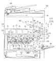
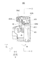
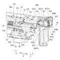
図1は、本実施の形態に係る画像形成装置100を正面から視た概略断面図である。
[Entire configuration of image forming apparatus]
FIG. 1 is a schematic cross-sectional view of an image forming apparatus 100 according to the present embodiment as viewed from the front.

図1に示す画像形成装置100は、外部から伝達された画像データに応じて、記録用紙等のシートP(この例では記録用紙)に対して多色及び単色の画像を形成するカラー画像形成装置である。画像形成装置100は、原稿読取装置108と、画像形成装置本体110とを備えており、画像形成装置本体110には、画像形成部102とシート搬送系103とが設けられている。   An image forming apparatus 100 shown in FIG. 1 is a color image forming apparatus that forms multicolor and single color images on a sheet P such as recording paper (recording paper in this example) in accordance with image data transmitted from the outside. It is. The image forming apparatus 100 includes a document reading device 108 and an image forming apparatus main body 110, and the image forming apparatus main body 110 is provided with an image forming unit 102 and a sheet conveying system 103.

画像形成部102は、露光ユニット1、複数の現像ユニット2〜2、複数の感光体ドラム3〜3、複数のクリーニング部4〜4、複数の帯電器5〜5、中間転写ベルトユニット6、複数のトナーカートリッジユニット21〜21及び定着ユニット7を備えている。   The image forming unit 102 includes an exposure unit 1, a plurality of developing units 2-2, a plurality of photosensitive drums 3-3, a plurality of cleaning units 4-4, a plurality of chargers 5-5, an intermediate transfer belt unit 6, a plurality of units. Toner cartridge units 21 to 21 and a fixing unit 7.

また、シート搬送系103は、給紙トレイ81、手差し給紙トレイ82、排出トレイ15及びシート排出装置400を備えている。   The sheet conveyance system 103 includes a paper feed tray 81, a manual paper feed tray 82, a discharge tray 15, and a sheet discharge device 400.

画像形成装置本体110の上部には、原稿(図示省略)が載置される透明ガラスからなる原稿載置台92が設けられ、原稿載置台92の下部には原稿を読み取るための光学ユニット90が設けられている。また、原稿載置台92の上側には原稿読取装置108が設けられている。原稿読取装置108は、原稿載置台92の上に自動で原稿を搬送する。また、原稿読取装置108は、画像形成装置本体110に対して前側開きで回動自在に取り付けられており、原稿載置台92の上を開放することにより原稿を手置きで載置できるようになっている。   An upper part of the image forming apparatus main body 110 is provided with an original placing table 92 made of transparent glass on which an original (not shown) is placed, and an optical unit 90 for reading the original is provided below the original placing base 92. It has been. A document reading device 108 is provided above the document table 92. The document reading device 108 automatically conveys the document on the document placing table 92. Further, the document reading device 108 is attached to the image forming apparatus main body 110 so as to be pivotable by opening the front side, and the document can be manually placed by opening the document placing table 92. ing.

原稿読取装置108は、自動的に搬送される原稿又は原稿載置台92上に載置された原稿を読み取ることができる。原稿読取装置108で読み取られた原稿の画像は、画像データとして画像形成装置本体110に送られ、画像形成装置本体110において画像データに基づき形成された画像がシートPに記録される。   The document reading device 108 can read a document that is automatically conveyed or a document placed on the document placing table 92. The original image read by the original reading device 108 is sent as image data to the image forming apparatus main body 110, and an image formed based on the image data in the image forming apparatus main body 110 is recorded on the sheet P.

画像形成装置100において扱われる画像データは、複数色(この例ではブラック(K)、シアン(C)、マゼンタ(M)、イエロー(Y)の各色)を用いたカラー画像に応じたものである。従って、現像ユニット2〜2、感光体ドラム3〜3、クリーニング部4〜4、帯電器5〜5及びトナーカートリッジユニット21〜21は、各色に応じた複数種類(この例では4種類)の画像を形成するようにそれぞれ複数個(この例では4個ずつ設けられ、それぞれブラック、シアン、マゼンタ、イエロー)に設定され、これらによって複数(この例では4つ)の画像ステーションが構成されている。   Image data handled in the image forming apparatus 100 corresponds to a color image using a plurality of colors (in this example, black (K), cyan (C), magenta (M), and yellow (Y)). . Accordingly, the developing units 2-2, the photosensitive drums 3-3, the cleaning units 4-4, the chargers 5-5, and the toner cartridge units 21-21 have a plurality of types (in this example, four types) of images corresponding to each color. In this example, a plurality of (four in this example are provided, each of which is black, cyan, magenta, and yellow), and a plurality (four in this example) of image stations are configured.

帯電器5〜5は、感光体ドラム3〜3の表面を所定の電位に均一に帯電させるための帯電手段であり、図1に示すようなチャージャ型の他、接触型であるローラ型やブラシ型の帯電器を用いることができる。   The chargers 5 to 5 are charging means for uniformly charging the surfaces of the photosensitive drums 3 to 3 to a predetermined potential. In addition to the charger type as shown in FIG. 1, a roller type or brush that is a contact type A type charger can be used.

露光ユニット1は、レーザ出射部及び反射ミラーを備えたレーザスキャニングユニットとして構成されている。露光ユニット1には、レーザビームを走査するポリゴンミラーと、ポリゴンミラーによって反射されたレーザ光を感光体ドラム3〜3に導くためのレンズやミラー等の光学素子とが設けられている。   The exposure unit 1 is configured as a laser scanning unit including a laser emitting unit and a reflection mirror. The exposure unit 1 is provided with a polygon mirror that scans a laser beam and optical elements such as lenses and mirrors for guiding the laser beam reflected by the polygon mirror to the photosensitive drums 3 to 3.

露光ユニット1は、入力された画像データに応じて、帯電された感光体ドラム3〜3をそれぞれ露光することにより、画像データに応じた静電潜像をそれぞれの感光体ドラム3〜3の表面に形成する。   The exposure unit 1 exposes the charged photosensitive drums 3 to 3 in accordance with the input image data, so that an electrostatic latent image corresponding to the image data is displayed on the surface of each of the photosensitive drums 3 to 3. To form.

トナーカートリッジユニット21〜21は、トナーを収容するユニットであり、現像ユニット2〜2の現像槽へトナーが供給されるようになっている。画像形成装置本体110において、トナーカートリッジユニット21〜21から現像ユニット2〜2の現像槽へ供給されるトナーは、該現像槽における現像剤のトナー濃度が一定になるように制御される。   The toner cartridge units 21 to 21 are units for storing toner, and the toner is supplied to the developing tanks of the developing units 2 and 2. In the image forming apparatus main body 110, the toner supplied from the toner cartridge units 21 to 21 to the developing tanks of the developing units 2 and 2 is controlled so that the toner density of the developer in the developing tank is constant.

現像ユニット2〜2は、それぞれの感光体ドラム3〜3上に形成された静電潜像を4色(Y,M,C,K)のトナーにより顕像化するものである。また、クリーニング部4〜4は、現像及び画像転写後における感光体ドラム3〜3上の表面に残留したトナーを除去、回収する。   The developing units 2 to 2 visualize the electrostatic latent images formed on the respective photosensitive drums 3 to 3 with toners of four colors (Y, M, C, and K). The cleaning units 4 to 4 remove and collect toner remaining on the surfaces of the photosensitive drums 3 to 3 after development and image transfer.

感光体ドラム3〜3の上方に配設されている中間転写ベルトユニット6は、中間転写体として作用する中間転写ベルト61、中間転写ベルト駆動ローラ62、中間転写ベルト従動ローラ63、複数の中間転写ローラ64〜64及び中間転写ベルトクリーニングユニット65を備えている。   The intermediate transfer belt unit 6 disposed above the photosensitive drums 3 to 3 includes an intermediate transfer belt 61 that acts as an intermediate transfer member, an intermediate transfer belt driving roller 62, an intermediate transfer belt driven roller 63, and a plurality of intermediate transfer belts. Rollers 64 to 64 and an intermediate transfer belt cleaning unit 65 are provided.

中間転写ローラ64〜64は、Y,M,C,Kの各色に対応して4本設けられている。中間転写ベルト駆動ローラ62は、中間転写ベルト従動ローラ63及び中間転写ローラ64〜64と共に中間転写ベルト61を張架し、回転駆動されることで、中間転写ベルト61が移動方向Mに周回移動され、それに伴い中間転写ベルト従動ローラ63及び中間転写ローラ64〜64が従動回転される。   Four intermediate transfer rollers 64 to 64 are provided corresponding to the respective colors Y, M, C, and K. The intermediate transfer belt drive roller 62 stretches the intermediate transfer belt 61 together with the intermediate transfer belt driven roller 63 and the intermediate transfer rollers 64 to 64 and is driven to rotate, whereby the intermediate transfer belt 61 is moved in the moving direction M. Accordingly, the intermediate transfer belt driven roller 63 and the intermediate transfer rollers 64 to 64 are driven to rotate.

各中間転写ローラ64〜64は、感光体ドラム3〜3上に形成されたトナー像を中間転写ベルト61上に転写するための転写バイアスが印加される。   Each of the intermediate transfer rollers 64 to 64 is applied with a transfer bias for transferring the toner image formed on the photosensitive drums 3 to 3 onto the intermediate transfer belt 61.

中間転写ベルト61は、感光体ドラム3〜3に接触するように設けられている。中間転写ベルト61は、感光体ドラム3〜3に形成された各色のトナー像を順次重ねて転写されることによって、表面にカラーのトナー像(多色トナー像)が形成される。   The intermediate transfer belt 61 is provided in contact with the photosensitive drums 3 to 3. The intermediate transfer belt 61 forms a color toner image (a multicolor toner image) on the surface by sequentially transferring the toner images of the respective colors formed on the photosensitive drums 3 to 3 in a superimposed manner.

感光体ドラム3〜3から中間転写ベルト61へのトナー像の転写は、中間転写ベルト61の裏側に接触している中間転写ローラ64〜64によって行われる。中間転写ローラ64〜64には、トナー像を転写するために高電圧の転写バイアス〔トナーの帯電極性(−)とは逆極性(+)の高電圧〕が印加される。   Transfer of the toner image from the photosensitive drums 3 to 3 to the intermediate transfer belt 61 is performed by intermediate transfer rollers 64 to 64 that are in contact with the back side of the intermediate transfer belt 61. A high-voltage transfer bias (a high voltage having a polarity (+) opposite to the toner charging polarity (−)) is applied to the intermediate transfer rollers 64 to 64 in order to transfer the toner image.

既述のとおり、各感光体ドラム3〜3上で各色相に応じて顕像化されたトナー像は、中間転写ベルト61上で積層される。中間転写ベルト61上で積層されたトナー像は、中間転写ベルト61の周回移動によって、シートPと中間転写ベルト61との接触位置に配設された二次転写機構部を構成する転写ローラ10によってシートP上に転写される。   As described above, the toner images visualized according to the hues on the photosensitive drums 3 to 3 are stacked on the intermediate transfer belt 61. The toner images stacked on the intermediate transfer belt 61 are transferred by the transfer roller 10 constituting the secondary transfer mechanism unit disposed at the contact position between the sheet P and the intermediate transfer belt 61 by the circumferential movement of the intermediate transfer belt 61. Transferred onto the sheet P.

このとき、転写ローラ10は、中間転写ベルト61との間で転写ニップが形成された状態で、トナーをシートPに転写させるための電圧〔トナーの帯電極性(−)とは逆極性(+)の高電圧〕が印加される。転写ローラ10及び中間転写ベルト駆動ローラ62が互いに圧接されることで転写ローラ10と中間転写ベルト61との間には転写ニップが形成される。ここで、転写ローラ10による中間転写ベルト61上からシートP上へのトナー像の転写にあたり、シートP上に転写されずに中間転写ベルト61上に残存したトナーは、中間転写ベルトクリーニングユニット65によって除去、回収される。   At this time, the transfer roller 10 is a voltage for transferring the toner onto the sheet P in a state where the transfer nip is formed with the intermediate transfer belt 61 [a polarity (+) opposite to the toner charging polarity (−)]. High voltage] is applied. A transfer nip is formed between the transfer roller 10 and the intermediate transfer belt 61 by the transfer roller 10 and the intermediate transfer belt driving roller 62 being pressed against each other. Here, when the toner image is transferred from the intermediate transfer belt 61 onto the sheet P by the transfer roller 10, the toner remaining on the intermediate transfer belt 61 without being transferred onto the sheet P is transferred by the intermediate transfer belt cleaning unit 65. Removed and recovered.

給紙トレイ81は、画像形成(印刷)されるシートPを予め収容しておくトレイであり、画像形成装置本体110における露光ユニット1の下方に設けられている。また、手差し給紙トレイ82には、画像形成(印刷)されるシートPが載置される。   The paper feed tray 81 is a tray that previously stores sheets P on which image formation (printing) is performed, and is provided below the exposure unit 1 in the image forming apparatus main body 110. In addition, a sheet P on which an image is formed (printed) is placed on the manual paper feed tray 82.

排出トレイ15は、画像形成装置本体110における画像形成部102の上方に設けられており、画像形成(印刷)済みのシートPをフェイスダウンで集積する。排出トレイ15は、シートPの排出方向Y1においてシートPを載置する載置面15aの上流側が下流側よりも低くなる構成とされている。   The discharge tray 15 is provided above the image forming unit 102 in the image forming apparatus main body 110, and stacks sheets P on which image formation (printing) has been completed face-down. The discharge tray 15 is configured such that the upstream side of the placement surface 15a on which the sheet P is placed is lower than the downstream side in the discharge direction Y1 of the sheet P.

また、画像形成装置本体110には、給紙トレイ81及び手差し給紙トレイ82から送られてきたシートPを、転写ローラ10及び定着ユニット7を経て、排出トレイ15に送るためのシート搬送路Sが設けられている。シート搬送路Sの近傍には、ピックアップローラ11a,11b、複数の(この例では第1から第4)搬送ローラ12a〜12d、レジストローラ13、転写ローラ10、定着ユニット7におけるヒートローラ71及び加圧ローラ72、排出前ローラ14、排出ローラ部31が配設されている。   Further, in the image forming apparatus main body 110, a sheet conveyance path S for sending the sheet P sent from the paper feed tray 81 and the manual paper feed tray 82 to the discharge tray 15 through the transfer roller 10 and the fixing unit 7. Is provided. In the vicinity of the sheet conveyance path S, pickup rollers 11a and 11b, a plurality of (in this example, first to fourth) conveyance rollers 12a to 12d, a registration roller 13, a transfer roller 10, a heat roller 71 in the fixing unit 7, and a heating roller A pressure roller 72, a pre-discharge roller 14, and a discharge roller unit 31 are disposed.

第1から第4搬送ローラ12a〜12dは、シートPの搬送を促進、補助するための小型のローラである。第1及び第2搬送ローラ12a,12bは、シート搬送路Sに沿って設けられており、第3及び第4搬送ローラ12c,12dは、シート搬送路Sから分岐部Saで分岐した反転搬送路Srに設けられている。また、ピックアップローラ11aは、給紙トレイ81のシート供給側の近傍に備えられ、給紙トレイ81からシートPを1枚ずつピックアップしてシート搬送路Sに供給する。同様に、ピックアップローラ11bは、手差し給紙トレイ82のシート供給側の近傍に備えられ、手差し給紙トレイ82からシートPを1枚ずつピックアップしてシート搬送路Sに供給する。   The first to fourth transport rollers 12a to 12d are small rollers for promoting and assisting the transport of the sheet P. The first and second conveyance rollers 12a and 12b are provided along the sheet conveyance path S, and the third and fourth conveyance rollers 12c and 12d are the reverse conveyance paths branched from the sheet conveyance path S at the branch portion Sa. Sr is provided. The pickup roller 11 a is provided in the vicinity of the sheet supply side of the sheet feed tray 81, picks up the sheets P one by one from the sheet feed tray 81, and supplies them to the sheet conveyance path S. Similarly, the pickup roller 11 b is provided near the sheet supply side of the manual sheet feed tray 82, picks up sheets P one by one from the manual sheet feed tray 82, and supplies the sheet P to the sheet conveyance path S.

また、レジストローラ13は、シート搬送路Sを搬送されているシートPを一旦保持するものである。そして、レジストローラ13は、感光体ドラム3〜3上のトナー像の先端とシートPの搬送方向Yにおける下流側端(先端P1)を合わせるタイミングでシートPを転写ローラ10と中間転写ベルト61との間の転写ニップに搬送する。   The registration roller 13 temporarily holds the sheet P being conveyed through the sheet conveyance path S. The registration roller 13 transfers the sheet P to the transfer roller 10 and the intermediate transfer belt 61 at a timing when the leading edge of the toner image on the photosensitive drums 3 to 3 is aligned with the downstream end (leading edge P1) in the conveyance direction Y of the sheet P. To the transfer nip.

排出前ローラ14は、シート搬送路Sにおいて分岐部SaよりもシートPの搬送方向Yにおける下流側、かつ、排出ローラ部31よりもシートPの搬送方向Yにおける上流側に設けられている。排出前ローラ14は、第2搬送ローラ12bから分岐部Saを経て送られてきたシートPを排出ローラ部31に向けて搬送する。   The pre-discharge roller 14 is provided on the downstream side in the conveyance direction Y of the sheet P with respect to the branch portion Sa in the sheet conveyance path S and on the upstream side in the conveyance direction Y of the sheet P with respect to the discharge roller portion 31. The pre-discharge roller 14 conveys the sheet P sent from the second conveyance roller 12b through the branch portion Sa toward the discharge roller unit 31.

定着ユニット7は、未定着トナー像をシートPに定着するものであり、定着ローラとして作用するヒートローラ71及び加圧ローラ72を備えている。ヒートローラ71は、回転駆動されることで、従動回転される加圧ローラ72と共にシートPを挟持しつつシートPを搬送するようになっている。また、ヒートローラ71は、内側に設けられたヒータ71aによって加熱され、温度検出器71bからの信号に基づき所定の定着温度に維持されるようになっている。ヒータ71aにより加熱されたヒートローラ71は、加圧ローラ72と共にシートPに転写された多色トナー像をシートPに熱圧着することにより、多色トナー像を溶融、混合、圧接してシートPに対して熱定着させる。   The fixing unit 7 fixes an unfixed toner image on the sheet P, and includes a heat roller 71 and a pressure roller 72 that act as a fixing roller. The heat roller 71 is rotated to convey the sheet P while sandwiching the sheet P together with the pressure roller 72 that is driven to rotate. The heat roller 71 is heated by a heater 71a provided on the inner side, and is maintained at a predetermined fixing temperature based on a signal from the temperature detector 71b. The heat roller 71 heated by the heater 71a heat-presses the multicolor toner image transferred onto the sheet P together with the pressure roller 72 to the sheet P, thereby melting, mixing, and pressing the multicolor toner image. Heat fix.

このように構成された画像形成装置100において、シートPに対して片面印刷が要求されたときには、給紙トレイ81又は手差し給紙トレイ82からシートPを供給し、シート搬送路Sに沿って設けられた第1搬送ローラ12aによってレジストローラ13までシートPを搬送する。次に、シートPの先端P1と中間転写ベルト61上のトナー像の先端を整合するタイミングで転写ローラ10によってシートPを搬送し、シートP上にトナー像を転写する。その後、シートPを定着ユニット7に通過させることによってシートP上の未定着トナーを熱で溶融、固着し、第2搬送ローラ12b、排出前ローラ14及び排出ローラ部31を経て排出トレイ15上に排出する。   In the image forming apparatus 100 configured as described above, when single-sided printing is requested for the sheet P, the sheet P is supplied from the sheet feeding tray 81 or the manual sheet feeding tray 82 and provided along the sheet conveyance path S. The sheet P is conveyed to the registration roller 13 by the first conveyance roller 12a. Next, the sheet P is conveyed by the transfer roller 10 at a timing when the leading end P1 of the sheet P and the leading end of the toner image on the intermediate transfer belt 61 are aligned, and the toner image is transferred onto the sheet P. Thereafter, the unfixed toner on the sheet P is melted and fixed by heat by passing the sheet P through the fixing unit 7, and passes through the second transport roller 12 b, the pre-discharge roller 14, and the discharge roller unit 31 to the discharge tray 15. Discharge.

次に、シート仕分部300について図2から図7を参照しながら以下に説明するが、図1において、説明していない符号の構成要素については、のちほど説明する。   Next, the sheet sorting unit 300 will be described below with reference to FIG. 2 to FIG. 7, but constituent elements that are not described in FIG. 1 will be described later.

[シート仕分部]
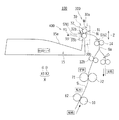
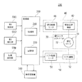
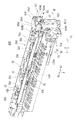
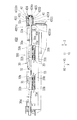
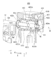
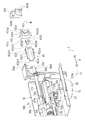
図2は、図1に示すシート排出装置400における排出ローラ部31及びその周辺部分を示す概略側面図である。図3は、図1に示す画像形成装置100の制御系のシステムブロック図である。図4は、図1に示すシート排出装置400におけるシート仕分部300をシートPの排出方向Y1上流側から視た概略側面図である。図5は、図1に示すシート排出装置400をシートPの排出方向Y1上流側の斜め上方から視た概略斜視図である。図6は、図5に示すシート排出装置400の概略平面図である。また、図7は、図5に示すシート排出装置400において排出ガイド部材410を除去して一部を断面にした状態を示す概略斜視図である。
[Sheet sorting department]
FIG. 2 is a schematic side view showing the discharge roller portion 31 and its peripheral portion in the sheet discharge apparatus 400 shown in FIG. FIG. 3 is a system block diagram of a control system of the image forming apparatus 100 shown in FIG. FIG. 4 is a schematic side view of the sheet sorting unit 300 in the sheet discharging apparatus 400 shown in FIG. 1 as viewed from the upstream side in the sheet P discharging direction Y1. FIG. 5 is a schematic perspective view of the sheet discharging apparatus 400 shown in FIG. 1 as viewed obliquely from the upstream side in the sheet P discharging direction Y1. FIG. 6 is a schematic plan view of the sheet discharge apparatus 400 shown in FIG. FIG. 7 is a schematic perspective view showing a state in which the discharge guide member 410 is removed and a part of the sheet discharge device 400 shown in FIG.

図2から図7に示すように、本実施の形態に係るシート排出装置400は、シートPを排出する一対の排出ローラ32,33を備え、一対の排出ローラ32,33によりシートPを排出するにあたり、一対の排出ローラ32,33を一対の排出ローラ32,33の回転軸線方向Xにシフト移動させる構成とされている。   As shown in FIGS. 2 to 7, the sheet discharge device 400 according to the present embodiment includes a pair of discharge rollers 32 and 33 that discharge the sheet P, and discharges the sheet P by the pair of discharge rollers 32 and 33. In this case, the pair of discharge rollers 32 and 33 are configured to shift in the rotational axis direction X of the pair of discharge rollers 32 and 33.

シート排出装置400は、シートPを所定の排出方向Y1に向けて(この例では排出トレイ15へ)排出する一対の排出ローラ32,33を回転軸線方向X(スラスト方向)に沿ってシフト移動させることにより一対の排出ローラ32,33にて排出されるシートPを仕分けるシート仕分部300を備えている。なお、シート排出装置400は、排出トレイ15を備えていてもよい。   The sheet discharge device 400 shifts a pair of discharge rollers 32 and 33 that discharge the sheet P in a predetermined discharge direction Y1 (to the discharge tray 15 in this example) along the rotation axis direction X (thrust direction). Accordingly, a sheet sorting unit 300 that sorts the sheets P discharged by the pair of discharge rollers 32 and 33 is provided. The sheet discharge device 400 may include a discharge tray 15.

シート仕分部300は、排出ローラ部31を有する排出ローラシフトユニット30と、回転駆動装置40(図3及び図4参照)と、シフト駆動装置50(図3から図5及び図7参照)とを備えている。   The sheet sorting unit 300 includes a discharge roller shift unit 30 having a discharge roller unit 31, a rotation driving device 40 (see FIGS. 3 and 4), and a shift driving device 50 (see FIGS. 3 to 5 and 7). I have.

排出ローラシフトユニット30は、画像形成装置本体110に対して排出ローラ部31の回転軸線方向Xに沿って往復移動自在に設けられている。この例では、排出ローラシフトユニット30は、回転軸線方向Xに沿って往復移動自在とされた摺動部材30b(具体的にはスライドレール)(図2参照)を介して画像形成装置本体110に支持されている。なお、摺動部材30bは、従来公知の構成とすることができ、ここでは詳しい説明は省略する。   The discharge roller shift unit 30 is provided so as to be reciprocally movable along the rotation axis direction X of the discharge roller portion 31 with respect to the image forming apparatus main body 110. In this example, the discharge roller shift unit 30 is attached to the image forming apparatus main body 110 via a sliding member 30b (specifically, a slide rail) (see FIG. 2) that is reciprocally movable along the rotation axis direction X. It is supported. In addition, the sliding member 30b can be set as a conventionally well-known structure, and detailed description is abbreviate | omitted here.

また、排出ローラシフトユニット30の本体フレーム30a(シート排出装置400の本体の一例)には、位置検知部SNp(図3及び図4参照)に検知される被検知片30c(具体的には被検知片)(図4参照)が設けられている。   The main body frame 30a of the discharge roller shift unit 30 (an example of the main body of the sheet discharge device 400) has a detection piece 30c (specifically, a target) to be detected by the position detection unit SNp (see FIGS. 3 and 4). Detection piece) (see FIG. 4) is provided.

排出ローラ部31は、シートPを排出トレイ15へ排出するものである。具体的には、排出ローラ部31は、駆動側の一方の排出ローラ32(ローラの一例)及び従動側の他方の排出ローラ33からなる一対の排出ローラ32,33を備えている。なお、この例では、一対の排出ローラ32,33のうち、一方の排出ローラ32が駆動ローラとされ、他方の排出ローラ33が従動ローラとされているが、一方の排出ローラ32及び他方の排出ローラ33の双方が駆動ローラとされていてもよい。   The discharge roller unit 31 discharges the sheet P to the discharge tray 15. Specifically, the discharge roller unit 31 includes a pair of discharge rollers 32 and 33 including one drive-side discharge roller 32 (an example of a roller) and the other driven-side discharge roller 33. In this example, of the pair of discharge rollers 32 and 33, one discharge roller 32 is a driving roller and the other discharge roller 33 is a driven roller. Both of the rollers 33 may be drive rollers.

詳しくは、一方の排出ローラ32は、ローラ軸32a(図4から図7参照)と、ローラ軸32aに同軸上に固定された複数(この例では4つ)のローラ部材32b〜32bとを備えている。他方の排出ローラ33は、ローラ軸33a(図4参照)と、ローラ軸33aの同軸上に一方の排出ローラ32におけるローラ部材32bに対向して固定された複数(この例では4つ)のローラ部材33b〜33bとを備えている。また、排出ローラ部31は、他方の排出ローラ33におけるローラ部材33bを一方の排出ローラ32におけるローラ部材32bに向けて付勢する付勢部材34(この例では巻きバネ)(図4参照)をさらに備えている。   Specifically, one discharge roller 32 includes a roller shaft 32a (see FIGS. 4 to 7) and a plurality (four in this example) of roller members 32b to 32b fixed coaxially to the roller shaft 32a. ing. The other discharge roller 33 includes a roller shaft 33a (see FIG. 4) and a plurality of (four in this example) rollers fixed on the same axis as the roller shaft 33a so as to face the roller member 32b of the one discharge roller 32. Members 33b to 33b. Further, the discharge roller unit 31 includes a biasing member 34 (in this example, a winding spring) that biases the roller member 33b of the other discharge roller 33 toward the roller member 32b of the one discharge roller 32 (see FIG. 4). It has more.

一対の排出ローラ32,33及び付勢部材34は、排出ローラシフトユニット30の本体フレーム30aに設けられている。一対の排出ローラ32,33のうち少なくとも一方(この例では一方の排出ローラ32)は、少なくとも一方の端部(この例では回転軸線方向Xにおける一方側X1の端部)が回転駆動装置40に接続されている。   The pair of discharge rollers 32 and 33 and the biasing member 34 are provided on the main body frame 30 a of the discharge roller shift unit 30. At least one of the pair of discharge rollers 32 and 33 (in this example, one discharge roller 32) has at least one end (in this example, the end on one side X1 in the rotation axis direction X) at the rotational drive device 40. It is connected.

具体的には、一方の排出ローラ32におけるローラ軸32aは、単一のものとされており、排出ローラシフトユニット30の本体フレーム30aに対して回転軸線α(図4参照)回りに回転自在に設けられている。   Specifically, the roller shaft 32a of one discharge roller 32 is a single roller, and is rotatable about a rotation axis α (see FIG. 4) with respect to the main body frame 30a of the discharge roller shift unit 30. Is provided.

他方の排出ローラ33におけるローラ軸33aは、回転軸線方向Xに沿って複数(この例では2つ)並設されており、それぞれ、複数(この例では2つ)のローラ部材33b,33bが固定されている。他方の排出ローラ33におけるローラ軸33a,33aは、ローラ部材33b,33bが対応する一方の排出ローラ32におけるローラ部材32b,32bと対峙するように、排出ローラシフトユニット30の本体フレーム30aに対して回転軸線回りに回転自在に、かつ、上下方向Zに沿って往復移動自在に設けられている。そして、排出ローラ部31は、シートPが一方の排出ローラ32と他方の排出ローラ33との間のニップ部N(図2及び図4参照)において他方の排出ローラ33にて押圧された状態で挟持されつつ搬送されるようになっている。   A plurality (two in this example) of roller shafts 33a of the other discharge roller 33 are arranged along the rotation axis direction X, and a plurality (two in this example) of roller members 33b and 33b are fixed. Has been. The roller shafts 33a and 33a in the other discharge roller 33 are opposed to the main body frame 30a of the discharge roller shift unit 30 so that the roller members 33b and 33b face the roller members 32b and 32b in the corresponding one discharge roller 32. It is provided so as to be rotatable around the rotation axis and reciprocating along the vertical direction Z. The discharge roller unit 31 is in a state in which the sheet P is pressed by the other discharge roller 33 in the nip portion N (see FIGS. 2 and 4) between the one discharge roller 32 and the other discharge roller 33. It is conveyed while being pinched.

付勢部材34は、複数(この例では2つ)の他方の排出ローラ33におけるローラ軸33a,33aに対応して複数(この例では2つ)の付勢部材34,34からなっている。付勢部材34,34は、他方の排出ローラ33を一方の排出ローラ32に向けて付勢するようになっており、他方の排出ローラ33におけるローラ軸33a,33aと、排出ローラシフトユニット30の本体フレーム30aの一方の排出ローラ32とは反対側の位置との間に配置されている。なお、付勢部材34,34による他方の排出ローラ33の一方の排出ローラ32への押圧力は、シートPが適正に搬送される程度の圧力となっている。   The urging member 34 includes a plurality (two in this example) of urging members 34 and 34 corresponding to the roller shafts 33a and 33a of the other (two in this example) other discharge rollers 33. The urging members 34 and 34 urge the other discharge roller 33 toward the one discharge roller 32, and the roller shafts 33 a and 33 a of the other discharge roller 33 and the discharge roller shift unit 30. The main body frame 30a is disposed between a position opposite to the one discharge roller 32. Note that the pressing force of the other discharge roller 33 to the one discharge roller 32 by the urging members 34, 34 is such a pressure that the sheet P is properly conveyed.

回転駆動装置40は、一方の排出ローラ32を回転駆動するものである。回転駆動装置40は、回転駆動部〔この例では排出駆動モータ41(具体的にはステッピングモータ)〕(図3及び図4参照)と、排出駆動モータ41からの回転駆動力を一方の排出ローラ32に伝達する駆動伝達機構42(図3から図7参照)とを備えている。   The rotation drive device 40 drives one discharge roller 32 to rotate. The rotation drive unit 40 includes a rotation drive unit [in this example, a discharge drive motor 41 (specifically, a stepping motor)] (see FIGS. 3 and 4) and a rotation drive force from the discharge drive motor 41 on one discharge roller. And a drive transmission mechanism 42 (see FIGS. 3 to 7) that transmits to 32.

排出駆動モータ41は、回転軸41a(図4参照)が回転軸線方向Xに沿うように画像形成装置本体110に設けられている。排出駆動モータ41の回転軸41aには、駆動ギヤ41b(図4参照)が固定されている。駆動ギヤ41bは、回転駆動伝達部材421(図4、図5、図7参照)に噛合している。また、駆動ギヤ41bには、回転駆動伝達部材421との予め定めた所定の距離が短くなることを規制する円板状の規制部材41b1(図4参照)が設けられている。この例では、駆動ギヤ41bと規制部材41b1とは一体形成されている。   The discharge drive motor 41 is provided in the image forming apparatus main body 110 so that the rotation shaft 41a (see FIG. 4) is along the rotation axis direction X. A drive gear 41b (see FIG. 4) is fixed to the rotation shaft 41a of the discharge drive motor 41. The drive gear 41b meshes with the rotational drive transmission member 421 (see FIGS. 4, 5, and 7). In addition, the drive gear 41b is provided with a disc-shaped restricting member 41b1 (see FIG. 4) that restricts a predetermined distance from the rotational drive transmission member 421 from being shortened. In this example, the drive gear 41b and the regulating member 41b1 are integrally formed.

駆動伝達機構42は、排出駆動モータ41からの回転駆動力により一方の排出ローラ32を回転軸線α回りに回転させ、かつ、一方の排出ローラ32の回転軸線方向Xへのスライド移動を許容しつつ一方の排出ローラ32を支持する機能を有している。なお、駆動ギヤ41bと駆動伝達機構42との間に1つのギヤ、又は、複数のギヤからなるギヤトレインが設けられて駆動ギヤ41b及び駆動伝達機構42と噛合するよいになっていてもよい。駆動伝達機構42については、後ほど詳しく説明する。   The drive transmission mechanism 42 rotates one discharge roller 32 about the rotation axis α by the rotational driving force from the discharge drive motor 41 and allows the one discharge roller 32 to slide in the rotation axis direction X. It has a function of supporting one discharge roller 32. In addition, a gear train including one gear or a plurality of gears may be provided between the drive gear 41b and the drive transmission mechanism 42 so as to mesh with the drive gear 41b and the drive transmission mechanism 42. The drive transmission mechanism 42 will be described in detail later.

シフト駆動装置50は、排出ローラ部31(この例では排出ローラシフトユニット30)をシフト駆動して回転軸線方向X(シフト方向)にシフト移動させるものである。シフト駆動装置50は、シフト駆動部〔この例ではシフト駆動モータ51(この例ではステッピングモータ)〕(図3から図5及び図7参照)と、排出ローラシフトユニット30をシフト移動させるシフト機構52(図3、図4及び図7参照)とを備えている。   The shift driving device 50 shift-drives the discharge roller unit 31 (discharge roller shift unit 30 in this example) and shifts it in the rotation axis direction X (shift direction). The shift drive device 50 includes a shift drive unit [in this example, a shift drive motor 51 (stepping motor in this example)] (see FIGS. 3 to 5 and 7) and a shift mechanism 52 that shifts the discharge roller shift unit 30. (See FIGS. 3, 4 and 7).

シフト駆動モータ51は、回転軸51a(図4、図5及び図7参照)が回転軸線方向Xに直交する方向(この例では上下方向Z)に沿うように画像形成装置本体110の本体フレーム110a(図4、図5及び図7参照)に設けられている。シフト駆動モータ51の回転軸51aには、駆動ギヤ51b(図4及び図7参照)が固定されている。駆動ギヤ41bは、回転駆動伝達部材421(図4、図5、図7参照)に噛合している。   The shift drive motor 51 has a main body frame 110a of the image forming apparatus main body 110 such that the rotation shaft 51a (see FIGS. 4, 5 and 7) is along a direction orthogonal to the rotation axis direction X (in this example, the vertical direction Z). (See FIG. 4, FIG. 5 and FIG. 7). A drive gear 51b (see FIGS. 4 and 7) is fixed to the rotation shaft 51a of the shift drive motor 51. The drive gear 41b meshes with the rotational drive transmission member 421 (see FIGS. 4, 5, and 7).

シフト機構52は、回転方向の駆動を直線方向の駆動に変換するラック・アンド・ピニオンのギヤで構成されており、回転軸線方向Xに沿って延びるラックギヤ52a(図4及び図7参照)と、ピニオンギヤ52b(図4及び図7参照)とを備えている。   The shift mechanism 52 is composed of a rack and pinion gear that converts a drive in the rotation direction into a drive in the linear direction, and a rack gear 52a (see FIGS. 4 and 7) extending along the rotation axis direction X. And a pinion gear 52b (see FIGS. 4 and 7).

ラックギヤ52aは、回転軸線方向Xに沿って排出ローラシフトユニット30に設けられている。ピニオンギヤ52bは、回転軸線方向Xに直交する方向(この例では上下方向Z)に沿って画像形成装置本体110の本体フレーム110aに固定された支持軸54(図4及び図7参照)に回転自在に設けられており、駆動ギヤ51b及びラックギヤ52aの双方と歯合している。これにより、シフト駆動モータ51の回転軸51aが一方向又は他方向に回転することで排出ローラシフトユニット30を回転軸線方向Xにおける一方側X1及び他方側X2に往復移動させることができる。   The rack gear 52 a is provided in the discharge roller shift unit 30 along the rotation axis direction X. The pinion gear 52b is rotatable on a support shaft 54 (see FIGS. 4 and 7) fixed to the main body frame 110a of the image forming apparatus main body 110 along a direction orthogonal to the rotation axis direction X (in this example, the vertical direction Z). And is engaged with both the drive gear 51b and the rack gear 52a. Thereby, the discharge roller shift unit 30 can be reciprocated to the one side X1 and the other side X2 in the rotation axis direction X by rotating the rotation shaft 51a of the shift drive motor 51 in one direction or the other direction.

[仕分け制御]
画像形成装置100は、制御部200(図3参照)と、第1検知部SN1(図2及び図3参照)と、第2検知部SN2(図2及び図3参照)と、位置検知部SNp(図3及び図4参照)とをさらに備えている。なお、制御部200は、シート排出装置400に備えられていてもよい。
[Sorting control]
The image forming apparatus 100 includes a control unit 200 (see FIG. 3), a first detection unit SN1 (see FIGS. 2 and 3), a second detection unit SN2 (see FIGS. 2 and 3), and a position detection unit SNp. (Refer to FIG. 3 and FIG. 4). Note that the control unit 200 may be provided in the sheet discharge device 400.

図3に示すように、制御部200は、CPU等の処理部210と、ROM(Read Only Memory)、RAM(Random Access Memory)及び書き換え可能な不揮発性メモリを含む記憶部220とを備えている。ROMは、処理部210が実行する処理の手順である制御プログラムを格納することができる。RAMは、作業用のワークエリアを提供することができる。   As shown in FIG. 3, the control unit 200 includes a processing unit 210 such as a CPU, and a storage unit 220 including a ROM (Read Only Memory), a RAM (Random Access Memory), and a rewritable nonvolatile memory. . The ROM can store a control program that is a procedure of processing executed by the processing unit 210. The RAM can provide a work area for work.

制御部200は、画像形成装置100におけるシート仕分部300のタイミング制御として回転駆動装置40及びシフト駆動装置50に対するタイミング制御を行うようになっている。かかるタイミング制御は、シート排出装置400が行ってもよいが、以下では、画像形成装置100が行う場合を例にとって説明する。   The control unit 200 performs timing control on the rotation driving device 40 and the shift driving device 50 as timing control of the sheet sorting unit 300 in the image forming apparatus 100. Such timing control may be performed by the sheet discharging apparatus 400, but in the following, a case where it is performed by the image forming apparatus 100 will be described as an example.

第1検知部SN1は、シートPが一対の排出ローラ32,33を通過しているか否かを検知するものである。具体的には、第1検知部SN1は、アクチュエータ付光透過型検知スイッチとされており、排出方向Y1において一対の排出ローラ32,33の下流側近傍に配置されている。第1検知部SN1は、制御部200の入力系に電気的に接続されている。これにより、第1検知部SN1は、一対の排出ローラ32,33をシートPが通過していないことを示すシート非通過信号(この例ではOFF信号)又は一対の排出ローラ32,33をシートPが通過していることを示すシート通過信号(この例ではON信号)を制御部200へ出力することができる。   The first detection unit SN1 detects whether or not the sheet P passes through the pair of discharge rollers 32 and 33. Specifically, the first detection unit SN1 is a light transmissive detection switch with an actuator, and is disposed in the vicinity of the downstream side of the pair of discharge rollers 32 and 33 in the discharge direction Y1. The first detection unit SN1 is electrically connected to the input system of the control unit 200. Thereby, the first detection unit SN1 detects the sheet non-passing signal (OFF signal in this example) indicating that the sheet P has not passed through the pair of discharge rollers 32 and 33 or the pair of discharge rollers 32 and 33 as the sheet P. A sheet passing signal (ON signal in this example) indicating that the sheet is passing can be output to the control unit 200.

第2検知部SN2は、排出方向Y1において一対の排出ローラ32,33よりも上流側の直近位置に配設された直近ローラ(この例では排出前ローラ14)をシートPが通過しているか否かを検知するものである。具体的には、第2検知部SN2は、アクチュエータ付光透過型検知スイッチとされており、排出方向Y1において直近ローラ(この例では排出前ローラ14)の下流側近傍に配置されている。第2検知部SN2は、制御部200の入力系に電気的に接続されている。これにより、第2検知部SN2は、直近ローラ(この例では排出前ローラ14)をシートPが通過していないことを示すシート非通過信号(この例ではOFF信号)又は直近ローラ(この例では排出前ローラ14)をシートPが通過していることを示すシート通過信号(この例ではON信号)を制御部200へ出力することができる。   Whether or not the sheet P passes through the closest roller (pre-discharge roller 14 in this example) disposed at the closest position upstream of the pair of discharge rollers 32 and 33 in the discharge direction Y1. Is to detect. Specifically, the second detection unit SN2 is a light transmission detection switch with an actuator, and is disposed in the vicinity of the downstream side of the nearest roller (the pre-discharge roller 14 in this example) in the discharge direction Y1. The second detection unit SN2 is electrically connected to the input system of the control unit 200. As a result, the second detection unit SN2 detects that the sheet P has not passed through the most recent roller (in this example, the pre-discharge roller 14) or the most recent roller (in this example, an OFF signal) or the most recent roller (in this example). A sheet passing signal (ON signal in this example) indicating that the sheet P is passing through the pre-discharge roller 14) can be output to the control unit 200.

位置検知部SNpは、排出ローラシフトユニット30が基準位置(具体的には回転軸線方向Xの中央位置、すなわち仕分けを行わない標準位置)に位置しているか否かを検知するものである。具体的には、位置検知部SNpは、排出ローラシフトユニット30の本体フレーム30aに設けられた被検知片30c(図4参照)を検知する光透過型センサされている。位置検知部SNpは、制御部200の入力系に電気的に接続されている。これにより、位置検知部SNpは、排出ローラシフトユニット30が基準位置に位置していることを示すユニット有信号(この例ではOFF信号)又は排出ローラシフトユニット30が基準位置に位置していないことを示すユニット無信号(この例ではON信号)を制御部200へ出力することができる。   The position detection unit SNp detects whether or not the discharge roller shift unit 30 is located at a reference position (specifically, a central position in the rotation axis direction X, that is, a standard position where sorting is not performed). Specifically, the position detection unit SNp is a light transmission type sensor that detects a detected piece 30c (see FIG. 4) provided on the main body frame 30a of the discharge roller shift unit 30. The position detection unit SNp is electrically connected to the input system of the control unit 200. As a result, the position detection unit SNp has a unit presence signal (OFF signal in this example) indicating that the discharge roller shift unit 30 is positioned at the reference position or the discharge roller shift unit 30 is not positioned at the reference position. A unit non-signal indicating ON (in this example, an ON signal) can be output to the control unit 200.

詳しくは、制御部200は、所定の回転方向W(この例ではシートPが排出される方向)(図2,図5,図7参照)への回転を指示する回転指示信号を排出駆動モータ41へ送信して排出駆動モータ41を駆動させる。これにより、制御部200は、駆動伝達機構42を介して排出ローラシフトユニット30における一方の排出ローラ32を所定の回転方向Wに回転駆動させることができる。   Specifically, the control unit 200 outputs a rotation instruction signal instructing rotation in a predetermined rotation direction W (in this example, the direction in which the sheet P is discharged) (see FIGS. 2, 5, and 7). And the discharge drive motor 41 is driven. As a result, the control unit 200 can rotationally drive one discharge roller 32 in the discharge roller shift unit 30 in the predetermined rotation direction W via the drive transmission mechanism 42.

また、制御部200は、基準位置を基準にして排出ローラシフトユニット30を回転軸線方向Xの一方側X1(図4に示す例では右側の方向)へ移動(この例では15mm移動)させる回転、及び、排出ローラシフトユニット30を回転軸線方向Xの他方側X2(図4に示す例では左側の方向)へ移動(この例では15mm移動)させる回転を指示する移動指示信号をシフト駆動モータ51へ送信してシフト駆動モータ51をパルス駆動させる。これにより、制御部200は、シフト機構52を介して排出ローラシフトユニット30を一方側X1、及び、他方側X2にシフト駆動させることができる。   Further, the controller 200 rotates (moves 15 mm in this example) the discharge roller shift unit 30 to one side X1 (in the example shown in FIG. 4, the right side) of the rotation axis direction X with reference to the reference position. A movement instruction signal for instructing rotation to move the discharge roller shift unit 30 to the other side X2 in the rotation axis direction X (left direction in the example shown in FIG. 4) (15 mm in this example) is sent to the shift drive motor 51. The shift driving motor 51 is pulse-driven by transmission. Accordingly, the control unit 200 can drive the discharge roller shift unit 30 to shift to the one side X1 and the other side X2 via the shift mechanism 52.

以上説明したように、画像形成装置100では、制御部200からの回転指示信号によって排出駆動モータ41が駆動されることにより排出駆動モータ41からの駆動力が駆動伝達機構42に伝達され、これにより、一方の排出ローラ32が所定の回転方向Wに回転駆動する。そして、排出ローラ部31によりシートPを排出するにあたり、仕分け動作を行わない場合には、排出ローラシフトユニット30を基準位置に位置させる一方、仕分け動作を行う場合には、排出ローラシフトユニット30を基準位置に位置させた状態で移動指示信号によってシフト駆動モータ51を駆動することによりシフト駆動モータ51からの駆動力をシフト機構52に伝達し、これにより、排出ローラシフトユニット30を一方側X1又は他方側X2へシフト移動させる。かくして、シート仕分部300を備えたシート排出装置400では、シートPを一対の排出ローラ32,33により排出方向Y1に排出するにあたり、シート仕分部300により回転軸線方向Xの一方側X1及び/又は他方側X2(この例では回転軸線方向Xの一方側X1及び他方側X2)に沿ってシフト移動させることができる。ここで、制御部200は、シート仕分部300により、排出ローラシフトユニット30を一方側X1又は他方側X2へシフト移動させながらシートPを排出方向Y1に排出するようにしてもよいし、排出ローラシフトユニット30を一方側X1又は他方側X2へシフト移動させた後、シートPを排出方向Y1に搬送するようにしてもてよい。   As described above, in the image forming apparatus 100, the drive force from the discharge drive motor 41 is transmitted to the drive transmission mechanism 42 by driving the discharge drive motor 41 according to the rotation instruction signal from the control unit 200, thereby One discharge roller 32 is rotationally driven in a predetermined rotational direction W. When the sorting operation is not performed when the sheet P is discharged by the discharge roller unit 31, the discharge roller shift unit 30 is positioned at the reference position. On the other hand, when the sorting operation is performed, the discharge roller shift unit 30 is When the shift drive motor 51 is driven by the movement instruction signal in the state where it is positioned at the reference position, the driving force from the shift drive motor 51 is transmitted to the shift mechanism 52, and thereby the discharge roller shift unit 30 is moved to the one side X 1 or Shift to the other side X2. Thus, in the sheet discharge device 400 including the sheet sorting unit 300, when the sheet P is discharged in the discharge direction Y1 by the pair of discharge rollers 32 and 33, one side X1 in the rotation axis direction X and / or It can be shifted along the other side X2 (in this example, one side X1 and the other side X2 in the rotational axis direction X). Here, the control unit 200 may cause the sheet sorting unit 300 to discharge the sheet P in the discharge direction Y1 while shifting the discharge roller shift unit 30 to the one side X1 or the other side X2, or the discharge roller. After shifting the shift unit 30 to the one side X1 or the other side X2, the sheet P may be conveyed in the discharge direction Y1.

なお、シート仕分部300は、前記した構成については限定されるものではなく、従来公知の何れの構成を採用してもよい。   The sheet sorting unit 300 is not limited to the above-described configuration, and any conventionally known configuration may be adopted.

[駆動伝達機構]
次に、駆動伝達機構42について図2から図7に加えて図8から図17を参照しながら以下に説明する。
[Drive transmission mechanism]
Next, the drive transmission mechanism 42 will be described below with reference to FIGS. 8 to 17 in addition to FIGS.

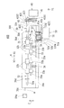
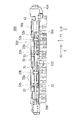
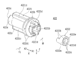
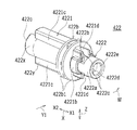
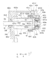
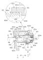
図8は、図5に示すシート排出装置400を回転軸線方向Xにおける一方側X1から視た概略側面図である。図9は、図5に示すシート排出装置400の図8に示すC−C線に沿った概略断面図である。図10は、図7に示すシート排出装置400の回転軸線方向Xにおける一方側X1部分を示す概略斜視図である。図11は、図7に示すシート排出装置400における駆動伝達機構42部分を拡大して示す概略斜視図である。図12は、図10及び図11に示す駆動伝達機構42を構成する部材を分解して示す分解斜視図である。図13は、駆動伝達機構42におけるスライド保持部材422のスライド保持部材本体4221及び軸部材4222を示す斜視図である。図14は、軸部材4222がスライド保持部材本体4221に係合した状態を示す斜視図である。図15は、一方の排出ローラ32が回転軸線方向Xにおける一方側X1の最も外側にシフト移動している状態での駆動伝達機構42部分を直角に切り欠いた状態を示す概略断面図である。図16は、一方の排出ローラ32が回転軸線方向Xにおける一方側X1の最も外側にシフト移動している状態での駆動伝達機構42部分の図8に示すC−C線に沿った概略断面図である。図17は、駆動伝達機構42部分の図8に示すC−C線に沿った概略断面図であってスライド保持部材422の回転軸線方向Xにおける外側の端部の外周面422aに設けられた近接部422bと回転駆動伝達部材421における受け入れ部4211の内周面4211aとの隙間状態を説明するための概略断面図である。なお、図9において、付勢部材34は図示を省略している。   FIG. 8 is a schematic side view of the sheet discharging apparatus 400 shown in FIG. 5 as viewed from one side X1 in the rotation axis direction X. FIG. 9 is a schematic cross-sectional view of the sheet discharge device 400 shown in FIG. 5 along the line CC shown in FIG. FIG. 10 is a schematic perspective view showing a portion on one side X1 in the rotation axis direction X of the sheet discharge apparatus 400 shown in FIG. FIG. 11 is an enlarged schematic perspective view showing the drive transmission mechanism 42 in the sheet discharging apparatus 400 shown in FIG. FIG. 12 is an exploded perspective view showing the members constituting the drive transmission mechanism 42 shown in FIGS. 10 and 11 in an exploded manner. FIG. 13 is a perspective view showing the slide holding member main body 4221 and the shaft member 4222 of the slide holding member 422 in the drive transmission mechanism 42. FIG. 14 is a perspective view showing a state in which the shaft member 4222 is engaged with the slide holding member main body 4221. FIG. 15 is a schematic cross-sectional view showing a state in which the drive transmission mechanism 42 is cut out at a right angle in a state in which one discharge roller 32 is shifted to the outermost side on one side X1 in the rotation axis direction X. FIG. 16 is a schematic cross-sectional view taken along the line CC in FIG. 8 of the drive transmission mechanism 42 in a state where one discharge roller 32 is shifted to the outermost side on one side X1 in the rotation axis direction X. It is. FIG. 17 is a schematic cross-sectional view of the drive transmission mechanism 42 along the line CC shown in FIG. 8, and the proximity provided on the outer peripheral surface 422 a of the outer end in the rotation axis direction X of the slide holding member 422. FIG. 11 is a schematic cross-sectional view for explaining a state of a gap between a portion 422b and an inner peripheral surface 4211a of a receiving portion 4211 in the rotational drive transmission member 421. In FIG. 9, the urging member 34 is not shown.

−駆動伝達機構の構成−
駆動伝達機構42は、回転軸線方向Xにシフト移動される一方の排出ローラ32(以下、単に排出ローラ32という。)に回転駆動力を伝達するものである。駆動伝達機構42は、所定の回転方向W(図2、図5、図7、図8、図10から図15参照)(この例ではシートPの排出方向Y1)に回転駆動される回転駆動伝達部材421(図4、図5、図7から図12及び図15から16参照)と、排出ローラ32を回転軸線α回りに回転させつつ回転軸線方向Xにスライド自在に保持するスライド保持部材422(図4、図7及び図9から16参照)と、回転駆動伝達部材421及びスライド保持部材422の間に介装される一方向クラッチ423(ワンウェイクラッチ)(図4、図7、図9から図12及び図15から16参照)とを備えている。
-Configuration of drive transmission mechanism-
The drive transmission mechanism 42 transmits a rotational driving force to one discharge roller 32 (hereinafter simply referred to as the discharge roller 32) shifted in the rotational axis direction X. The drive transmission mechanism 42 is a rotational drive transmission that is rotationally driven in a predetermined rotational direction W (see FIGS. 2, 5, 7, 8, and 10 to 15) (in this example, the discharge direction Y1 of the sheet P). A member 421 (see FIGS. 4, 5, 7 to 12 and 15 to 16) and a slide holding member 422 (slidably holding in the rotational axis direction X while rotating the discharge roller 32 around the rotational axis α) ( 4, 7, and 9 to 16) and a one-way clutch 423 (one-way clutch) interposed between the rotation drive transmission member 421 and the slide holding member 422 (see FIGS. 4, 7, and 9 to 9). 12 and FIGS. 15 to 16).

ここで、回転駆動伝達部材421としては、例えば、他のギヤと噛合されるギヤ、或いは、ベルトやチェーン等が掛けられるプーリー等を挙げることができる。この例では、回転駆動伝達部材421は、ギヤとされている。   Here, examples of the rotational drive transmission member 421 include a gear meshed with another gear, a pulley on which a belt, a chain, or the like is hung. In this example, the rotational drive transmission member 421 is a gear.

そして、一方向クラッチ423は、回転駆動伝達部材421からの回転駆動力をスライド保持部材422に伝達する一方、回転駆動伝達部材421に対するスライド保持部材422の所定の回転方向Wの相対回転を許容する構成とされている。すなわち、一方向クラッチ423は、回転が許容される方向が排出方向Y1とされ、かつ、回転が禁止される方向(回転しない方向)が排出方向Y1とは反対方向とされている。   The one-way clutch 423 transmits the rotational driving force from the rotational drive transmission member 421 to the slide holding member 422, while allowing relative rotation of the slide holding member 422 in the predetermined rotational direction W with respect to the rotational drive transmission member 421. It is configured. That is, in the one-way clutch 423, the direction in which the rotation is allowed is the discharge direction Y1, and the direction in which the rotation is prohibited (the direction that does not rotate) is the direction opposite to the discharge direction Y1.

シート排出装置400では、排出ローラ32を回転軸線方向Xにシフト移動させるにあたり、シフト駆動装置50を駆動してシフト機構52により排出ローラシフトユニット30を回転軸線方向Xにシフト移動させる。このとき、排出ローラ32におけるローラ軸32aは、スライド保持部材422において回転軸線方向Xに往復移動する。また、排出ローラ32を回転軸線α回りの所定の回転方向Wに回転させるにあたり、回転駆動装置40を駆動して駆動伝達機構42(回転駆動伝達部材421、一方向クラッチ423及びスライド保持部材422)により排出ローラ32を回転軸線α回りに所定の回転方向Wに回転させる。   In the sheet discharge device 400, when shifting the discharge roller 32 in the rotation axis direction X, the shift driving device 50 is driven and the shift mechanism 52 shifts the discharge roller shift unit 30 in the rotation axis direction X. At this time, the roller shaft 32 a of the discharge roller 32 reciprocates in the rotation axis direction X on the slide holding member 422. Further, when rotating the discharge roller 32 in a predetermined rotation direction W around the rotation axis α, the rotation driving device 40 is driven to drive drive mechanism 42 (rotation drive transmission member 421, one-way clutch 423 and slide holding member 422). As a result, the discharge roller 32 is rotated in the predetermined rotation direction W around the rotation axis α.

本実施の形態では、スライド保持部材422により排出ローラ32を回転軸線α回りに回転させつつ回転軸線方向Xにスライド自在に保持するので、コンパクトでありながら排出ローラ32を回転軸線α回りに回転させると共に回転軸線方向Xにシフト移動させるための構成を容易に実現させることができる(図10ほか参照)。さらに、一方向クラッチ423は、所定の回転方向Wに回転駆動される回転駆動伝達部材421及びスライド保持部材422の間に介装されるので、一方向クラッチ423への回転軸線方向Xにおける負荷を抑制することができると共に、回転軸線方向Xの長さに制約されることなく、従って、比較的短い単一の一方向クラッチ423を用いることができ、これにより、低コストを実現させつつ簡単でかつコンパクトな駆動伝達機構42を実現させることができる。しかも、一方向クラッチ423は、回転駆動伝達部材421からの回転駆動力をスライド保持部材422に伝達するので、排出ローラ32を予め定めた所定の周速度で回転駆動させることができる。この例では、回転駆動伝達部材421からの回転駆動力が一方向クラッチ423及びスライド保持部材422を介して伝達された排出ローラ32によりシートPを予め定めた所定のシート排出速度〔具体的には画像形成装置本体110において画像形成を行う速度である画像形成速度(プロセス速度)〕で排出することができる。そして、一方向クラッチ423は、回転駆動伝達部材421に対するスライド保持部材422の所定の回転方向Wの相対回転を許容する構成とされているので、所定の回転方向Wに回転駆動される排出ローラ32をより速い周速度で回転駆動伝達部材421の回転に影響を与えることなく強制的に回転させることができる。この例では、シートPを排出する途中で(具体的にはシートPの後端P2が排出前ローラ14を通過した後)シート排出速度がたとえより速く(具体的にはシートPを導入するときのシート搬送速度よりも速く)なったとしてもシートPを確実に排出させることができる。   In this embodiment, since the discharge roller 32 is rotated about the rotation axis α while being slidably held in the rotation axis direction X by the slide holding member 422, the discharge roller 32 is rotated about the rotation axis α while being compact. At the same time, it is possible to easily realize a configuration for shifting in the rotational axis direction X (see FIG. 10 and others). Further, since the one-way clutch 423 is interposed between the rotation drive transmission member 421 and the slide holding member 422 that are driven to rotate in a predetermined rotation direction W, a load in the rotation axis direction X is applied to the one-way clutch 423. It can be suppressed and is not limited by the length in the rotational axis direction X, and therefore, a relatively short single one-way clutch 423 can be used, which makes it easy to achieve a low cost. In addition, a compact drive transmission mechanism 42 can be realized. In addition, the one-way clutch 423 transmits the rotational driving force from the rotational driving transmission member 421 to the slide holding member 422, so that the discharge roller 32 can be rotationally driven at a predetermined peripheral speed. In this example, a predetermined sheet discharge speed [specifically, a sheet P is discharged by the discharge roller 32 to which the rotational driving force from the rotational drive transmission member 421 is transmitted via the one-way clutch 423 and the slide holding member 422. The image can be discharged at an image forming speed (process speed) which is a speed at which image formation is performed in the image forming apparatus main body 110. The one-way clutch 423 is configured to allow relative rotation in the predetermined rotation direction W of the slide holding member 422 with respect to the rotation drive transmission member 421. Therefore, the discharge roller 32 that is rotationally driven in the predetermined rotation direction W. Can be forcibly rotated at a higher peripheral speed without affecting the rotation of the rotational drive transmission member 421. In this example, while the sheet P is being discharged (specifically, after the trailing end P2 of the sheet P has passed the pre-discharge roller 14), the sheet discharging speed is even faster (specifically, when the sheet P is introduced). The sheet P can be surely discharged even if it is faster than the sheet conveying speed.

このように、本実施の形態によれば、一方向クラッチ423への回転軸線方向Xにおける負荷を抑制することができると共に、低コストを実現させつつ駆動伝達機構42が簡単でかつコンパクトな構成でありながら、所定の回転方向Wに回転駆動される排出ローラ32をより速い周速度で強制的に回転させることができる。この例では、シートPを排出する途中でシート排出速度がたとえより速く(具体的にはシートPを導入するときのシート搬送速度よりも速く)なるようにシートPが排出させられたとしてもシートPを確実に排出させることができる。例えば、後処理を行う速度である処理速度が画像形成装置本体110の画像形成速度よりも速い後処理装置500(図3参照)が画像形成装置本体110に装着されている場合において、画像形成速度と後処理速度とを整合させて或いは可及的に整合させるために、シートPの後端P2が画像形成装置本体110における排出前ローラ14を通過した後、シートPを排出する途中でシート排出速度がたとえ画像形成速度よりも速く(例えば後処理速度が画像形成速度よりも速い分速く)なるようにシートPが排出させられたとしてもシートPを確実に排出させることができる。   As described above, according to the present embodiment, the load in the rotational axis direction X to the one-way clutch 423 can be suppressed, and the drive transmission mechanism 42 has a simple and compact configuration while realizing low cost. However, the discharge roller 32 that is rotationally driven in the predetermined rotation direction W can be forcibly rotated at a higher peripheral speed. In this example, even if the sheet P is discharged while the sheet P is being discharged, even if the sheet P is discharged so that the sheet discharge speed becomes faster (specifically, faster than the sheet conveyance speed when the sheet P is introduced). P can be reliably discharged. For example, when the post-processing apparatus 500 (see FIG. 3) whose processing speed, which is the speed for performing post-processing, is faster than the image forming speed of the image forming apparatus main body 110 is mounted on the image forming apparatus main body 110, the image forming speed. In order to match the post-processing speed with the post-processing speed or as much as possible, the sheet P is discharged while the trailing end P2 of the sheet P passes through the pre-discharge roller 14 in the image forming apparatus main body 110 and then the sheet P is discharged. Even if the sheet P is discharged so that the speed is higher than the image forming speed (for example, the post-processing speed is higher than the image forming speed), the sheet P can be discharged reliably.

(第1実施形態)
スライド保持部材422は、スライド保持部材本体4221(図4、図7及び図9から16参照)と、スライド保持部材本体4221に設けられる軸部材4222(図4、図7及び図9から図17参照)とを有している。一方向クラッチ423は、回転駆動伝達部材421と軸部材4222との間に介装されており、回転駆動伝達部材421からの回転駆動力をスライド保持部材本体4221に軸部材4222を介して伝達する構成とされている。
(First embodiment)
The slide holding member 422 includes a slide holding member main body 4221 (see FIGS. 4, 7 and 9 to 16) and a shaft member 4222 (see FIGS. 4, 7 and 9 to 17) provided on the slide holding member main body 4221. ). The one-way clutch 423 is interposed between the rotation drive transmission member 421 and the shaft member 4222, and transmits the rotation driving force from the rotation drive transmission member 421 to the slide holding member main body 4221 via the shaft member 4222. It is configured.

こうすることで、軸部材4222を用いるといった簡単な構成でありながら、回転駆動伝達部材421からの回転駆動力をスライド保持部材本体4221に軸部材4222を介して伝達することができる。   By doing so, it is possible to transmit the rotational driving force from the rotational drive transmission member 421 to the slide holding member main body 4221 via the shaft member 4222, with a simple configuration using the shaft member 4222.

ところで、さらにコンパクトな駆動伝達機構42を実現させるという観点から、一方向クラッチ423として、回転駆動伝達部材に設けられる外輪と、外輪の内周面に設けられて一方向に回転する転動部材とを備えたもの(内輪レス構造の一方向クラッチ)を用いることが望まれる。   By the way, from the viewpoint of realizing a more compact drive transmission mechanism 42, as the one-way clutch 423, an outer ring provided on the rotary drive transmission member, a rolling member provided on the inner peripheral surface of the outer ring and rotating in one direction, (One-way clutch with an inner ring-less structure) is preferably used.

この点、一方向クラッチ423は、回転駆動伝達部材421に設けられる外輪4231(図16参照)と、外輪4231の内周面4231a(図16参照)に設けられて一方向に回転する転動部材4232(この例では複数の転動部材4232〜4232)(例えばローラ及び/又はボール)(図16参照)とを備えたもの(内輪レス構造の一方向クラッチ)とされている。ここで、内輪レス構造の一方向クラッチは、従来公知のものを用いることができ、ここでは詳しい説明を省略する。そして、軸部材4222は、剛性部材(具体的には硬度が転動部材4232〜4232の硬度と同等程度か又は転動部材4232〜4232の硬度よりも大きい剛性部材)とされており、外輪4231の内周面4231aに挿通されて外周面4222a(図7、図13から図16参照)が転動部材4232に接触して転動部材4232と共に回転する構成とされている。   In this regard, the one-way clutch 423 includes an outer ring 4231 (see FIG. 16) provided on the rotational drive transmission member 421 and a rolling member that is provided on the inner peripheral surface 4231a (see FIG. 16) of the outer ring 4231 and rotates in one direction. 4232 (in this example, a plurality of rolling members 4232 to 4232) (for example, rollers and / or balls) (see FIG. 16) (one-way clutch having an inner ring-less structure). Here, the conventionally known one-way clutch can be used as the inner ring-less structure, and detailed description thereof is omitted here. The shaft member 4222 is a rigid member (specifically, a rigid member whose hardness is approximately equal to the hardness of the rolling members 4232 to 4232 or greater than the hardness of the rolling members 4232 to 4232), and the outer ring 4231. The outer peripheral surface 4222a (see FIGS. 7 and 13 to 16) is in contact with the rolling member 4232 and rotates together with the rolling member 4232.

こうすることで、回転駆動伝達部材421からの回転駆動力を一方向クラッチ423の外輪4231及び転動部材4232を介して剛性部材とされた軸部材4222及びスライド保持部材本体4221を経て排出ローラ32に伝達する一方、転動部材4232により回転駆動伝達部材421に対するスライド保持部材422及び排出ローラ32の所定の回転方向Wの相対回転を許容することができる。そして、このような、外輪4231と転動部材4232とを備えた内輪レス構造の一方向クラッチ423を用いることで、さらにコンパクトな駆動伝達機構42を実現させることができる。   In this way, the rotational driving force from the rotational drive transmission member 421 is discharged through the outer ring 4231 and the rolling member 4232 of the one-way clutch 423 through the shaft member 4222 and the slide holding member main body 4221 which are rigid members. On the other hand, relative rotation of the slide holding member 422 and the discharge roller 32 in the predetermined rotation direction W with respect to the rotational drive transmission member 421 can be permitted by the rolling member 4232. Further, by using the one-way clutch 423 having an inner ring-less structure including the outer ring 4231 and the rolling member 4232, a more compact drive transmission mechanism 42 can be realized.

具体的には、回転駆動伝達部材421は、回転軸線方向Xに貫通した中空構造のものとされている。一方向クラッチ423は、外周面423a(図15から図17参照)が回転駆動伝達部材421の内周面421a(図15から図17参照)に固定(この例では圧入)されている。   Specifically, the rotation drive transmission member 421 has a hollow structure penetrating in the rotation axis direction X. The one-way clutch 423 has an outer peripheral surface 423a (see FIGS. 15 to 17) fixed (in this example, press-fitted) to an inner peripheral surface 421a (see FIGS. 15 to 17) of the rotational drive transmission member 421.

ところで、外輪4231と転動部材4232とを備えた内輪レス構造の一方向クラッチ423を用いる場合において、軸部材4222として比較的柔らかい樹脂のような部材や転動部材4232との接触部にメッキ処理が施されている部材を用いる場合には、軸部材4222が一方向クラッチ423における外輪4231及び転動部材4232を介して回転駆動伝達部材421からの回転駆動力をスライド保持部材422におけるスライド保持部材本体4221に伝達することに伴い軸部材4222の転動部材4232との接触部が削れるといった不都合が発生する恐れがある。そうすると、軸部材4222が回転駆動伝達部材421に対して双方向に回転自在となってしまい、排出ローラ32に対してシートPを排出させるための駆動力を付与することができない。   By the way, in the case of using a one-way clutch 423 having an inner ring-less structure including an outer ring 4231 and a rolling member 4232, a plating process is applied to a contact portion between the shaft member 4222 and a member such as a relatively soft resin or the rolling member 4232. In the case of using a member to which the shaft is provided, the shaft member 4222 receives the rotational driving force from the rotational driving transmission member 421 via the outer ring 4231 and the rolling member 4232 in the one-way clutch 423, and the slide holding member in the slide holding member 422. There is a possibility that inconvenience that the contact portion of the shaft member 4222 with the rolling member 4232 is scraped off due to transmission to the main body 4221. As a result, the shaft member 4222 is rotatable in both directions with respect to the rotational drive transmission member 421, and a driving force for discharging the sheet P cannot be applied to the discharge roller 32.

この点、軸部材4222は、剛性部材とされていることで、軸部材4222の転動部材4232との接触部が削れるといった不都合、ひいては排出ローラ32に対してシートPを排出させるための駆動力を付与することができないという不都合を効果的に防止することができる。   In this respect, the shaft member 4222 is a rigid member, so that the contact portion of the shaft member 4222 with the rolling member 4232 is scraped, and thus the driving force for causing the discharge roller 32 to discharge the sheet P. Can be effectively prevented.

なお、以上の構成は、内輪レス構造の一方向クラッチだけでなく、内輪のある一方向クラッチの場合にも好適に用いることができる。すなわち、内輪のある一方向クラッチに対しても係合ガタによる軸部材4222の削れを効果的に防止できるなど有効である。   The above configuration can be suitably used not only for a one-way clutch having an inner ring-less structure but also for a one-way clutch having an inner ring. In other words, it is effective for the one-way clutch having the inner ring to effectively prevent the shaft member 4222 from being scraped by the engagement play.

この例では、剛性部材とされた軸部材4222は、金属材料からなっている。こうすることで、軸部材4222を剛性部材とする構成を容易に実現させることができる。   In this example, the shaft member 4222, which is a rigid member, is made of a metal material. By doing so, it is possible to easily realize a configuration in which the shaft member 4222 is a rigid member.

金属材料としては、例えば、ステンレス鋼、チタン合金、炭素鋼などを挙げることができる。こうすることで、軸部材4222を作製し易くすることができ、軸部材4222を剛性部材とする構成を比較的安価にかつ容易に実現させることができる。この例では、軸部材4222は、ステンレス鋼からなっている。なお、剛性部材としては、金属材料の他に、例えば、カーボン樹脂やセラミックなどを挙げることができる。   Examples of the metal material include stainless steel, titanium alloy, and carbon steel. By doing so, the shaft member 4222 can be easily manufactured, and a configuration in which the shaft member 4222 is a rigid member can be realized relatively inexpensively and easily. In this example, the shaft member 4222 is made of stainless steel. In addition, as a rigid member, carbon resin, a ceramic, etc. can be mentioned other than a metal material, for example.

−軸部材の着脱構成−
軸部材4222は、スライド保持部材本体4221に対して着脱自在とさている。こうすることで、スライド保持部材本体4221と軸部材4222との組み立て作業性を向上させることができる。なお、軸部材4222は、圧入等により固定されていてもよい。
-Shaft member attachment / detachment configuration-
The shaft member 4222 is detachable from the slide holding member main body 4221. By doing so, the assembly workability of the slide holding member main body 4221 and the shaft member 4222 can be improved. The shaft member 4222 may be fixed by press fitting or the like.

詳しくは、軸部材4222は、スライド保持部材本体4221に対して回転軸線方向Xに挿脱自在、かつ、回転軸線α回りに相対回転不能に(所定の回転方向W及び回転方向Wとは反対方向に固定されるように)係合される。   Specifically, the shaft member 4222 can be inserted into and removed from the slide holding member main body 4221 in the rotation axis direction X and cannot rotate relative to the rotation axis α (the direction opposite to the predetermined rotation direction W and the rotation direction W). To be engaged).

こうすることで、回転駆動伝達部材421からの回転駆動力のスライド保持部材本体4221への軸部材4222を介する伝達を軸部材4222のスライド保持部材本体4221への係合といった簡単な構成で実現させることができる。   Thus, transmission of the rotational driving force from the rotational drive transmission member 421 to the slide holding member main body 4221 via the shaft member 4222 is realized with a simple configuration such as engagement of the shaft member 4222 to the slide holding member main body 4221. be able to.

この例では、スライド保持部材本体4221と軸部材4222とは、互いに係合することでスライド保持部材本体4221及び軸部材4222が伴回りする回り止め部4221b,4222b(図7、図12から図15参照)をそれぞれ有している。   In this example, the slide holding member main body 4221 and the shaft member 4222 are engaged with each other so that the slide holding member main body 4221 and the shaft member 4222 rotate together with the rotation preventing portions 4221b and 4222b (FIGS. 7, 12 to 15). Each).

こうすることで、スライド保持部材本体4221と軸部材4222とを軸部材4222がスライド保持部材本体4221に対して回転軸線α回りに相対回転しないように確実に係合することができる。   Thus, the slide holding member main body 4221 and the shaft member 4222 can be reliably engaged with each other so that the shaft member 4222 does not rotate relative to the slide holding member main body 4221 around the rotation axis α.

また、スライド保持部材本体4221における回り止め部4221bは、回転軸線方向Xにおける外側(この例では一方側X1)の端部に設けられている。軸部材4222における回り止め部4222bは、回転軸線方向における内側(この例では他方側X2)の端部に設けられている。   Further, the rotation preventing portion 4221b of the slide holding member main body 4221 is provided at an end portion on the outer side (in this example, one side X1) in the rotation axis direction X. The rotation preventing portion 4222b of the shaft member 4222 is provided at the inner end (in this example, the other side X2) in the rotation axis direction.

こうすることで、回転軸線方向Xにおける駆動伝達機構42のコンパクト化を実現させることができる。   By doing so, the drive transmission mechanism 42 in the rotation axis direction X can be made compact.

具体的には、スライド保持部材本体4221及び軸部材4222は、互いに、凹凸係合されている。スライド保持部材本体4221における回り止め部4221bは凹部とされ、かつ、軸部材4222における回り止め部4222bは凸部とされていてもよいし、スライド保持部材本体4221における回り止め部4221bは凸部とされ、かつ、軸部材4222における回り止め部4222bは凹部とされていてもよい。   Specifically, the slide holding member main body 4221 and the shaft member 4222 are engaged with each other in a concavo-convex manner. The anti-rotation portion 4221b in the slide holding member main body 4221 may be a concave portion, the anti-rotation portion 4222b in the shaft member 4222 may be a convex portion, and the anti-rotation portion 4221b in the slide holding member main body 4221 may be a convex portion. In addition, the rotation preventing portion 4222b of the shaft member 4222 may be a concave portion.

ここで、スライド保持部材本体4221としては、有底の円筒形状(有底円筒形状)のもの、中空部を貫通させた円筒形状(貫通円筒形状)のものを例示できる。また、軸部材4222としては、円柱形状のもの、有底の円筒形状(有底円筒形状)のもの、中空部を貫通させた円筒形状(貫通円筒形状)のものを例示できる。   Here, examples of the slide holding member main body 4221 include those having a bottomed cylindrical shape (bottomed cylindrical shape) and those having a hollow portion penetrating a hollow portion (through cylindrical shape). Further, examples of the shaft member 4222 include a columnar shape, a bottomed cylindrical shape (bottomed cylindrical shape), and a cylindrical shape (through-cylindrical shape) penetrating a hollow portion.

軸部材4222が円柱形状のもの又は有底円筒形状のものである場合、軸部材4222における回り止め部4222bを回転軸線方向Xから視て非円形状の凸部又は凹部〔例えばD状の凸部又は凹部(いわゆるDカット)や多角形状、楕円形状若しくは俵形状の凸部又は凹部〕とし、スライド保持部材本体4221における回り止め部4221bを軸部材4222における回り止め部4222bの形状に対応させた回転軸線方向Xから視て非円形状の凹部又は凸部とすることができる。   When the shaft member 4222 has a columnar shape or a cylindrical shape with a bottom, the non-circular convex portion or concave portion [for example, D-shaped convex portion when the rotation preventing portion 4222b of the shaft member 4222 is viewed from the rotation axis direction X. Or a concave portion (so-called D-cut), a polygonal shape, an elliptical shape or a ridge-shaped convex portion or a concave portion), and the rotation prevention portion 4221b of the slide holding member main body 4221 corresponds to the shape of the rotation prevention portion 4222b of the shaft member 4222. It can be set as a noncircular recessed part or convex part seeing from the axial direction X. FIG.

軸部材4222が貫通円筒形状のものである場合、軸部材4222における回り止め部4222bの回転軸線方向Xにおける一端部を周方向に沿って1箇所又は複数箇所で回転軸線方向Xに突出させた(例えば周方向に均等に突出させた)凸部、又は、周方向に沿って1箇所又は複数箇所で回転軸線方向Xに窪ませた(例えば周方向に均等に窪ませた)凹部とすることができる。また、スライド保持部材本体4221における回り止め部4221bの回転軸線方向Xにおける他端部を周方向に沿って1箇所又は複数箇所で窪ませた(例えば周方向に均等に窪ませた)凹部、又は、周方向に沿って1箇所又は複数箇所で突出させた(例えば周方向に均等に突出させた)凸部とすることができる。   When the shaft member 4222 has a through-cylindrical shape, one end portion in the rotation axis direction X of the rotation preventing portion 4222b of the shaft member 4222 is protruded in the rotation axis direction X at one or a plurality of locations along the circumferential direction ( For example, a convex portion that protrudes evenly in the circumferential direction, or a concave portion that is recessed in the rotation axis direction X at one or a plurality of locations along the circumferential direction (for example, recessed uniformly in the circumferential direction). it can. In addition, the other end portion in the rotation axis direction X of the rotation preventing portion 4221b in the slide holding member main body 4221 is recessed at one or a plurality of locations along the circumferential direction (for example, recessed uniformly at the circumferential direction), or , And a convex portion protruding at one or a plurality of locations along the circumferential direction (for example, protruding evenly in the circumferential direction).

この例では、スライド保持部材本体4221は、貫通円筒形状のものとされている。軸部材4222は、貫通円筒形状のものとされている。軸部材4222における回り止め部4222bは、回転軸線方向Xにおける他方側X2の端部を周方向に沿って2箇所で周方向に均等に(直径方向に揃うように)回転軸線方向Xに突出させた凸部とされている。スライド保持部材本体4221における回り止め部4221bは、回転軸線方向Xにおける一方側X1の端部を周方向に沿って2箇所で周方向に均等に(直径方向に揃うように)回転軸線方向Xに窪ませた凹部(具体的には回転軸線方向Xから視て俵形状の係止孔)とされている。   In this example, the slide holding member body 4221 has a through cylindrical shape. The shaft member 4222 has a through cylindrical shape. The rotation preventing portion 4222b of the shaft member 4222 causes the end of the other side X2 in the rotation axis direction X to protrude in the rotation axis direction X evenly in the circumferential direction (so as to be aligned in the diameter direction) at two locations along the circumferential direction. It is a convex part. The anti-rotation portion 4221b in the slide holding member main body 4221 has the end on one side X1 in the rotation axis direction X in the rotation axis direction X evenly in the circumferential direction at two locations along the circumferential direction (so as to be aligned in the diameter direction). A recessed portion (specifically, a hook-shaped locking hole as viewed from the rotation axis direction X) is formed.

−受け部材−
駆動伝達機構42は、回転駆動伝達部材421と共に一方向クラッチ423を介して回転軸線α回りに回転する軸部材4222を回転自在に支持する受け部材424(図5から図12、図15から図17参照)(具体的にはカバー部材)をさらに備えている。
-Receiving member-
The drive transmission mechanism 42 includes a receiving member 424 (FIGS. 5 to 12 and FIGS. 15 to 17) that rotatably supports a shaft member 4222 that rotates about the rotational axis α through a one-way clutch 423 together with the rotational drive transmission member 421. Reference) (specifically, a cover member) is further provided.

こうすることで、回転軸線α回りの回転する軸部材4222を受け部材424により確実に支持することができる。   Thus, the shaft member 4222 that rotates about the rotation axis α can be reliably supported by the receiving member 424.

詳しくは、受け部材424は、軸部材4222の回転軸線方向Xにおける一方側X1への移動を規制する規制部424a(図5、図7から図12、図15から図17参照)を有している。軸部材4222は、受け部材424における規制部424aに係合される係合部4222c(図7及び図9から図17参照)を有している。   Specifically, the receiving member 424 includes a restricting portion 424a (see FIGS. 5, 7 to 12, and 15 to 17) that restricts the movement of the shaft member 4222 to the one side X1 in the rotation axis direction X. Yes. The shaft member 4222 has an engaging portion 4222c (see FIGS. 7 and 9 to 17) that is engaged with the restricting portion 424a of the receiving member 424.

こうすることで、軸部材4222における係合部4222cにより軸部材4222の回転軸線α回りの相対回転を許容しつつ、受け部材424における規制部424aにより軸部材4222の回転軸線方向Xにおける一方側X1への移動(具体的には軸部材4222の抜け)を効果的に防止することができる。   In this way, while the relative rotation about the rotation axis α of the shaft member 4222 is allowed by the engaging portion 4222c of the shaft member 4222, the one side X1 in the rotation axis direction X of the shaft member 4222 is allowed by the restriction portion 424a of the receiving member 424. (Specifically, the shaft member 4222 is removed) can be effectively prevented.

具体的には、受け部材424は、排出ローラシフトユニット30の本体フレーム30aに取り外し可能に固定されている。   Specifically, the receiving member 424 is detachably fixed to the main body frame 30 a of the discharge roller shift unit 30.

この例では、受け部材424は、本体フレーム30aに1又は複数の固定部材SC(この例では2つの雄ネジ)(図5参照)により固定されている。本体フレーム30aの回転軸線方向Xにおける駆動伝達機構42が設けられる側の側面には、固定部材SC,SCを固定するための1又は複数の固定部30a1(この例では2箇所の雌ネジ孔)(図5及び図7参照)及び1又は複数の位置決め部30a2(この例では1つの位置決め突起)(図5及び図8参照)が設けられている。受け部材424には、本体フレーム30aにおける固定部30a1,30a1及び位置決め部30a2に対応する位置に貫通孔424b〜424b(図5、図7及び図8、図10から図12及び図15参照)が設けられている。本体フレーム30aに受け部材424を固定部材SC,SCにより確実に固定することができる。   In this example, the receiving member 424 is fixed to the main body frame 30a by one or a plurality of fixing members SC (two male screws in this example) (see FIG. 5). One or a plurality of fixing portions 30a1 (two female screw holes in this example) for fixing the fixing members SC, SC on the side surface of the main body frame 30a on the side where the drive transmission mechanism 42 in the rotation axis direction X is provided. (See FIGS. 5 and 7) and one or a plurality of positioning portions 30a2 (in this example, one positioning protrusion) (see FIGS. 5 and 8) are provided. The receiving member 424 has through holes 424b to 424b (refer to FIGS. 5, 7, and 8, and FIGS. 10 to 12, and 15) at positions corresponding to the fixing portions 30a1 and 30a1 and the positioning portion 30a2 in the main body frame 30a. Is provided. The receiving member 424 can be securely fixed to the main body frame 30a by the fixing members SC and SC.

−排出ローラの回り止め部材−
排出ローラ32には、スライド保持部材422と係合してスライド保持部材422を伴回りさせる回り止め部材32c(図4、図7、図9から図12及び図15から図17参照)が設けられている。回り止め部材32cは、排出ローラ32におけるローラ軸32aの回転軸線方向Xにおける端部(スライド保持部材422が設けられる側の端部)に設けられている。詳しくは、回り止め部材32cは、ローラ軸32aの回転軸線方向Xにおける一方側X1の端面から内側の近傍(該端面から回り止め部材32cを設けることができる程度の所定距離だけ内側)に設けられている。回り止め部材32cは、排出ローラ32が最も外側にシフト移動したときに、軸部材4222と近接(具体的には軸部材4222と接触しない程度に軸部材4222の近傍に位置)する構成とされている。
-Detent member for discharge roller-
The discharge roller 32 is provided with an anti-rotation member 32c (see FIGS. 4, 7, 9 to 12, and 15 to 17) that engages with the slide holding member 422 to rotate the slide holding member 422. ing. The anti-rotation member 32c is provided at the end of the discharge roller 32 in the rotational axis direction X of the roller shaft 32a (the end on the side where the slide holding member 422 is provided). Specifically, the rotation preventing member 32c is provided in the vicinity of the inner side from the end surface on one side X1 in the rotation axis direction X of the roller shaft 32a (inward from the end surface by a predetermined distance to the extent that the rotation preventing member 32c can be provided). ing. The rotation preventing member 32c is configured to be close to the shaft member 4222 (specifically, located in the vicinity of the shaft member 4222 so as not to contact the shaft member 4222) when the discharge roller 32 shifts to the outermost side. Yes.

こうすることで、回転軸線方向Xにおける駆動伝達機構42のさらなるコンパクト化を実現させることができる。   By doing so, the drive transmission mechanism 42 in the rotation axis direction X can be further reduced in size.

具体的には、回り止め部材32cは、ローラ軸32aの直径よりも小さい直径のピンとされている。回り止め部材32cの長さは、ローラ軸32aの直径よりも大きく、かつ、スライド保持部材本体4221に挿通される程度のサイズとなっている。ローラ軸32aには、回り止め部材32cが貫通する貫通孔32a1(図10から図12、図15から図17参照)が設けられている。回り止め部材32cは、ローラ軸32aにおける貫通孔32a1に固定(この例では圧入)されている。回り止め部材32cは、ローラ軸32aからローラ軸32aの径方向において均等に突出している。   Specifically, the rotation preventing member 32c is a pin having a diameter smaller than the diameter of the roller shaft 32a. The length of the anti-rotation member 32c is larger than the diameter of the roller shaft 32a and has a size enough to be inserted into the slide holding member main body 4221. The roller shaft 32a is provided with a through hole 32a1 (see FIGS. 10 to 12 and FIGS. 15 to 17) through which the rotation preventing member 32c passes. The rotation preventing member 32c is fixed (press-fit in this example) to the through hole 32a1 in the roller shaft 32a. The rotation preventing member 32c protrudes uniformly from the roller shaft 32a in the radial direction of the roller shaft 32a.

−軸部材の受け入れ部−
詳しくは、軸部材4222の回転軸線方向Xにおける内側(この例では他方側X2)の端部には、排出ローラ32が最も外側にシフト移動したときに、排出ローラ32におけるローラ軸32aの回転軸線方向Xにおける外側の端部32a2(図16及び図17参照)を受け入れる受け入れ部4222d(図12、図13、図16及び図17参照)が設けられている。
-Receiving part of shaft member-
Specifically, the rotation axis of the roller shaft 32a of the discharge roller 32 is located at the inner end (the other side X2 in this example) of the shaft member 4222 when the discharge roller 32 is shifted outward. A receiving portion 4222d (see FIGS. 12, 13, 16, and 17) that receives the outer end 32a2 (see FIGS. 16 and 17) in the direction X is provided.

こうすることで、回転軸線方向Xにおける駆動伝達機構42のさらなるコンパクト化を実現させることができる。   By doing so, the drive transmission mechanism 42 in the rotation axis direction X can be further reduced in size.

この例では、軸部材4222は、回転軸線方向Xにおける内側(この例では他方側X2)の端部において内径が回転軸線方向Xにおける外側に行くに従って段階的に(この例では2段階に)小さくされている。   In this example, the shaft member 4222 is smaller in steps (in this example, in two steps) as the inner diameter goes outward in the rotation axis direction X at the inner end (in this example, the other side X2) in the rotation axis direction X. Has been.

−スライド保持部材の係止案内部−
また、スライド保持部材422(具体的にはスライド保持部材本体4221)には、排出ローラ32のローラ軸32aにおける回り止め部材32cを排出ローラ32の回転方向Wで係止し、かつ、回転軸線方向Xに案内する係止案内部4221c(図7及び図9から図17参照)が設けられている。
-Locking guide part of slide holding member-
Further, the slide holding member 422 (specifically, the slide holding member main body 4221) locks the rotation preventing member 32c on the roller shaft 32a of the discharge roller 32 in the rotation direction W of the discharge roller 32, and the rotation axis direction. A locking guide portion 4221c (see FIGS. 7 and 9 to 17) for guiding to X is provided.

こうすることで、スライド保持部材422により排出ローラ32を回転軸線α回りに円滑に回転させながら回転軸線方向Xにスライド自在に確実に保持することができる。   By doing so, the discharge roller 32 can be securely held slidably in the rotation axis direction X while being smoothly rotated around the rotation axis α by the slide holding member 422.

具体的には、スライド保持部材本体4221は、円筒部材422x(図13及び図14参照)と、箱体422y(この例では中空の直方体)(図13及び図14参照)とが同軸上に合体したような構成とされている。箱体422yは、回転軸線方向Xにおけるサイズが円筒部材422xの回転軸線方向Xにおけるサイズよりも小さくされている。また、箱体422yは、径方向の一方のサイズが円筒部材422xの径方向における外形のサイズよりも大きくされ、かつ、径方向の他方のサイズが円筒部材422xの径方向における外形のサイズよりも小さくされている。そして、箱体422yの円筒部材422xからの突出部が係止案内部4221cを構成している。また、スライド保持部材422(具体的にはスライド保持部材本体4221)において、係止案内部4221cと、軸部材4222における回り止め部4222bと係合する回り止め部4221bとは、交差(この例では直角又は略直角に交差)している。   Specifically, in the slide holding member main body 4221, a cylindrical member 422x (see FIGS. 13 and 14) and a box 422y (in this example, a hollow rectangular parallelepiped) (see FIGS. 13 and 14) are coaxially combined. It is set as such. The size of the box 422y in the rotation axis direction X is smaller than the size of the cylindrical member 422x in the rotation axis direction X. The box body 422y has one radial size larger than the outer size in the radial direction of the cylindrical member 422x, and the other radial size is larger than the outer size in the radial direction of the cylindrical member 422x. It has been made smaller. And the protrusion part from the cylindrical member 422x of the box 422y comprises the latching guide part 4221c. Further, in the slide holding member 422 (specifically, the slide holding member main body 4221), the locking guide portion 4221c and the anti-rotation portion 4221b engaged with the anti-rotation portion 4222b of the shaft member 4222 intersect (in this example, Intersecting at right or near right angles).

−係止案内部の開放部−
また、係止案内部4221cの回転軸線方向Xにおける外側の端部(この例では回転軸線方向Xにおける一方側X1の端部)には、排出ローラ32の径方向に開放した開放部4221d(図13及び図14参照)が設けられている。
-Opening part of locking guide-
Further, an opening 4221d (see FIG. 5) opened in the radial direction of the discharge roller 32 at an outer end in the rotation axis direction X of the locking guide 4221c (in this example, the end on one side X1 in the rotation axis X). 13 and FIG. 14).

こうすることで、係止案内部4221cの回転軸線方向Xにおける外側の端部において径方向における係止案内部4221cのコンパクト化を実現させることができる。   By doing so, the locking guide portion 4221c in the radial direction can be made compact at the outer end in the rotation axis direction X of the locking guide portion 4221c.

−回転駆動伝達部材及びスライド保持部材の材料−
回転駆動伝達部材421とスライド保持部材422とは、互いに異なる材料で構成されている。こうすることで、回転駆動伝達部材421とスライド保持部材422とで要求される機能に対応させることができる。
-Materials for rotational drive transmission member and slide holding member-
The rotational drive transmission member 421 and the slide holding member 422 are made of different materials. By doing so, it is possible to correspond to the functions required by the rotation drive transmission member 421 and the slide holding member 422.

・回転駆動伝達部材の材料
例えば、回転駆動伝達部材421は、機能上強度が要求されることから、強度を有する材料で構成されている。こうすることで、回転駆動伝達部材421の強度を向上させることができる。回転駆動伝達部材421に用いることができる材料としては、例えば、ポリアセタール(POM:PolyOxyMethylene)、ポリアミド(PA:PolyAmide)、ポリフェニレンサルファイド(PPS:PolyPhenyleneSulfide)等を挙げることができる。また、回転駆動伝達部材421は、相手側の駆動伝達部材(この例では駆動ギヤ41b)との接触による摩擦抵抗に起因する騒音を低減させるという観点から、摺動グレード材料で形成されていてもよい。こうすることで、回転駆動伝達部材421と相手側の駆動伝達部材(この例では駆動ギヤ41b)との接触による摩擦抵抗を抑えることができ、それだけ騒音を低減させることができる。摺動グレード材料としては、代表的には、摺動性に優れた潤滑剤を含有した樹脂材料(例えばフッ素化合物、含油ポリエチレン等の潤滑剤を含んだポリアセタール、いわゆるポリアセタール摺動グレード材料)を例示できる。
-Material of a rotational drive transmission member For example, the rotational drive transmission member 421 is made of a material having strength because strength is required for its function. By doing so, the strength of the rotational drive transmission member 421 can be improved. Examples of materials that can be used for the rotation drive transmission member 421 include polyacetal (POM), polyamide (PA), polyphenylene sulfide (PPS), and the like. In addition, the rotational drive transmission member 421 may be formed of a sliding grade material from the viewpoint of reducing noise caused by frictional resistance due to contact with the drive transmission member on the other side (in this example, the drive gear 41b). Good. By doing so, it is possible to suppress the frictional resistance caused by the contact between the rotational drive transmission member 421 and the counterpart drive transmission member (in this example, the drive gear 41b), and to reduce the noise accordingly. Typical examples of the sliding grade material include a resin material containing a lubricant having excellent sliding properties (for example, a polyacetal containing a lubricant such as a fluorine compound or oil-containing polyethylene, a so-called polyacetal sliding grade material). it can.

・スライド保持部材の材料
また、スライド保持部材422は、機能上滑り性が要求されることから、滑り性を有する材料で構成されている。こうすることで、スライド保持部材422の滑り性を向上させることができる。スライド保持部材422に用いることができる材料としては、例えば、ポリアセタール(POM:PolyOxyMethylene)、ポリアミド(PA:PolyAmide)、ポリテトラフルオロエチレン(PTFE:PolyTetraFluoroEthylene)等を挙げることができる。
-Material of a slide holding member Moreover, since the slide holding member 422 is requested | required by the function from the slip property, it is comprised with the material which has a slip property. By doing so, the slipperiness of the slide holding member 422 can be improved. Examples of the material that can be used for the slide holding member 422 include polyacetal (POM), polyamide (PA), and polytetrafluoroethylene (PTFE).

−回転駆動伝達部材の係合部−
回転駆動伝達部材421は、この例では、基部421x(図12、図15及び図16参照)と、基部421xに外周部に全周に亘って設けられて相手側の回転駆動伝達部材(この例では駆動ギヤ41b)と係合する係合部421y(図12、図15及び図16参照)(この例ではギヤ歯)とを備えている。基部421x及び係合部421yは、一体形成されている。
-Engagement part of rotation drive transmission member-
In this example, the rotational drive transmission member 421 includes a base 421x (see FIGS. 12, 15 and 16), and a rotational drive transmission member (this example) provided on the outer periphery of the base 421x over the entire circumference. Then, an engaging portion 421y (see FIGS. 12, 15, and 16) (in this example, gear teeth) that engages with the drive gear 41b) is provided. The base part 421x and the engaging part 421y are integrally formed.

係合部421yは、基部421xにおける外周面の回転軸線方向Xにおける何れの位置に設けられていてもよいが、この例では、基部421xにおける外周面の回転軸線方向Xにおける内側(この例では他方側X2)の端部に設けられている。そして、基部421xの係合部421yよりも回転軸線方向Xにおける外側(この例では一方側X1)には、駆動ギヤ41bにおける規制部材41b1と当接して回転駆動伝達部材421と駆動ギヤ41bとのギヤ間の距離を規定する座421x1(図12、図15及び図16参照)が設けられている。この例では、座421x1は、係合部421yに隣接して設けられている。基部421x、係合部421y及び座421x1は、一体形成されている。   The engaging portion 421y may be provided at any position in the rotational axis direction X of the outer peripheral surface of the base portion 421x, but in this example, the inner side in the rotational axis direction X of the outer peripheral surface of the base portion 421x (the other in this example) At the end of the side X2). Then, on the outer side (one side X1 in this example) in the rotational axis direction X than the engaging portion 421y of the base portion 421x, the regulating member 41b1 in the drive gear 41b is brought into contact with the rotational drive transmission member 421 and the drive gear 41b. A seat 421x1 (see FIGS. 12, 15, and 16) that defines the distance between the gears is provided. In this example, the seat 421x1 is provided adjacent to the engaging portion 421y. The base portion 421x, the engaging portion 421y, and the seat 421x1 are integrally formed.

−一方向クラッチの配設位置−
一方向クラッチ423は、回転駆動伝達部材421の回転軸線方向Xにおける何れの位置に設けられていてもよいが、この例では、回転駆動伝達部材421の回転軸線方向Xにおける外側(この例では一方側X1)の端部に固定されている。
-Position of one-way clutch-
The one-way clutch 423 may be provided at any position in the rotation axis direction X of the rotation drive transmission member 421. In this example, the one-way clutch 423 is disposed outside the rotation drive transmission member 421 in the rotation axis direction X (one in this example). It is fixed to the end of the side X1).

こうすることで、回転駆動伝達部材421の回転軸線方向Xにおける内側(この例では他方側X2)のスペースを広くとることができ、従って、かかるスペースを排出ローラ32におけるローラ軸32aの回転軸線方向Xにおける移動スペースとすることができ、それだけ、駆動伝達機構42の回転軸線方向Xにおけるコンパクト化を実現させることができる。   In this way, a space on the inner side (in this example, the other side X2) in the rotational axis direction X of the rotational drive transmission member 421 can be widened. Therefore, this space can be taken in the rotational axis direction of the roller shaft 32a in the discharge roller 32. It can be set as the movement space in X, and the compactness in the rotation axis direction X of the drive transmission mechanism 42 can be realized.

具体的には、一方向クラッチ423は、基部421xにおける内周面の回転軸線方向Xにおける外側(この例では一方側X1)の端部に設けられている。   Specifically, the one-way clutch 423 is provided on the outer end (one side X1 in this example) of the inner peripheral surface of the base portion 421x in the rotation axis direction X.

−回転駆動伝達部材の受け入れ部−
回転駆動伝達部材421の回転軸線方向Xにおける内側(この例では他方側X2)の端部には、スライド保持部材422の回転軸線方向Xにおける外側(この例では一方側X1)の端部を受け入れる受け入れ部4211(図5、図7から図12、図15及び図16参照)が設けられている。
-Receiving part of rotational drive transmission member-
The end on the inner side (the other side X2 in this example) in the rotational axis direction X of the rotational drive transmission member 421 receives the end on the outer side (the one side X1 in this example) of the slide holding member 422 in the rotational axis direction X. A receiving portion 4211 (see FIGS. 5, 7 to 12, 15, and 16) is provided.

こうすることで、回転駆動伝達部材421に対してスライド保持部材422の回転軸線方向Xにおける外側(この例では一方側X1)の端部を確実に挿通させることができる。   By doing so, the end portion on the outer side (one side X1 in this example) in the rotation axis direction X of the slide holding member 422 can be reliably inserted into the rotation drive transmission member 421.

詳しくは、スライド保持部材422における開放部4221dは、係止案内部4221cの回転駆動伝達部材421における受け入れ部4211に挿通される部分を含んでいる。また、回転駆動伝達部材421において、受け入れ部4211の外周面に係合部421yが設けられている。   Specifically, the open portion 4221d of the slide holding member 422 includes a portion that is inserted into the receiving portion 4211 of the rotation drive transmission member 421 of the locking guide portion 4221c. Further, in the rotational drive transmission member 421, an engaging portion 421y is provided on the outer peripheral surface of the receiving portion 4211.

−スライド保持部材の近接部−
ところで、スライド保持部材422の外周面422a(図16及び図17参照)の回転軸線方向Xにおける外側(この例では一方側X1)の端部と回転駆動伝達部材421における受け入れ部4211の内周面4211a(図16及び図17参照)とが接触する場合、スライド保持部材422が回転駆動伝達部材421に対して回転軸線α回りに相対回転する際に、スライド保持部材422と回転駆動伝達部材421との摺接による異常音(摺接音)が発生し易い。一方、スライド保持部材422の外周面422aの回転軸線方向Xにおける外側(この例では一方側X1)の端部と回転駆動伝達部材421における受け入れ部4211の内周面4211aとが離間し過ぎる場合、負荷変動によりスライド保持部材422が回転軸線αに対して傾斜が大きくなり易く(いわばスライド保持部材422の首振りが大きくなり易く)、スライド保持部材422が回転駆動伝達部材421に対して回転軸線α回りに相対回転する際に、スライド保持部材422の回転軸線αに対する傾斜(スライド保持部材422の首振り)による異常音(例えばスライド保持部材422の震え音)が発生することがある。
-Proximity of slide holding member-
By the way, the outer peripheral surface 422a (see FIGS. 16 and 17) of the slide holding member 422 is arranged on the outer end (one side X1 in this example) in the rotational axis direction X and the inner peripheral surface of the receiving portion 4211 in the rotational drive transmission member 421. 4211a (see FIGS. 16 and 17), when the slide holding member 422 rotates relative to the rotation drive transmission member 421 around the rotation axis α, the slide holding member 422 and the rotation drive transmission member 421 An abnormal sound (sliding contact sound) due to sliding contact is likely to occur. On the other hand, when the outer end of the outer peripheral surface 422a of the slide holding member 422 in the rotation axis direction X (one side X1 in this example) and the inner peripheral surface 4211a of the receiving portion 4211 of the rotational drive transmission member 421 are too far apart, Due to the load fluctuation, the inclination of the slide holding member 422 tends to increase with respect to the rotation axis α (so that the swing of the slide holding member 422 tends to increase), and the slide holding member 422 rotates relative to the rotation drive transmission member 421. During relative rotation around, an abnormal sound (for example, a shaking noise of the slide holding member 422) due to the inclination of the slide holding member 422 with respect to the rotation axis α (swing of the slide holding member 422) may occur.

この点、スライド保持部材422(この例ではスライド保持部材本体4221)の外周面422aの回転軸線方向Xにおける外側(この例では一方側X1)の端部には、回転駆動伝達部材421における受け入れ部4211の内周面4211aに近接する近接部422b(図13、図14及び図17参照)が設けられている。   In this respect, the receiving portion of the rotational drive transmission member 421 is disposed at the outer end (one side X1 in this example) of the outer peripheral surface 422a of the slide holding member 422 (in this example, the slide holding member main body 4221) in the rotational axis direction X. A proximity portion 422b (see FIGS. 13, 14, and 17) adjacent to the inner peripheral surface 4211a of 4211 is provided.

こうすることで、スライド保持部材422が回転駆動伝達部材421に対して回転軸線α回りに相対回転する際に、スライド保持部材422と回転駆動伝達部材421とがたとえ摺接したとしてもスライド保持部材422と回転駆動伝達部材421との摺接による異常音の発生を効果的に防止することができる。しかも、負荷変動によるスライド保持部材422の回転軸線αに対する傾斜を回転駆動伝達部材421における受け入れ部4211のスライド保持部材422における近接部422bとの摺接により抑えることができ(いわばスライド保持部材422の首振りを小さくすることができ)、これにより、スライド保持部材422が回転駆動伝達部材421に対して回転軸線α回りに相対回転する際に、スライド保持部材422の回転軸線αに対する傾斜(スライド保持部材422の首振り)による異常音(例えばスライド保持部材422の震え音)の発生を抑制することができる。ここで、負荷変動によりスライド保持部材422が回転軸線αに対して傾斜する際のスライド保持部材422における近接部422bと回転駆動伝達部材421における受け入れ部4211との摺接音は、例えば、スライド保持部材422と回転駆動伝達部材421とが常時摺接しているときの異常音(摺接音)の大きさ及び/又は発生頻度よりも低い。   In this way, even when the slide holding member 422 and the rotation drive transmission member 421 are in sliding contact with each other when the slide holding member 422 rotates relative to the rotation drive transmission member 421 about the rotation axis α, the slide holding member Generation of abnormal noise due to sliding contact between 422 and the rotational drive transmission member 421 can be effectively prevented. In addition, the inclination of the slide holding member 422 with respect to the rotation axis α due to load fluctuation can be suppressed by sliding contact of the receiving portion 4211 of the rotational drive transmission member 421 with the adjacent portion 422b of the slide holding member 422 (so to speak of the slide holding member 422). Thus, when the slide holding member 422 rotates relative to the rotation drive transmission member 421 around the rotation axis α, the slide holding member 422 is inclined relative to the rotation axis α (slide holding). Occurrence of abnormal sound (for example, shaking sound of the slide holding member 422) due to the swinging of the member 422 can be suppressed. Here, the sliding contact sound between the proximity portion 422b of the slide holding member 422 and the receiving portion 4211 of the rotational drive transmission member 421 when the slide holding member 422 is inclined with respect to the rotation axis α due to load fluctuation is, for example, slide holding It is lower than the magnitude and / or frequency of occurrence of abnormal noise (sliding contact sound) when the member 422 and the rotational drive transmission member 421 are always in sliding contact.

詳しくは、近接部422bは、スライド保持部材422の回転駆動伝達部材421における受け入れ部4211と対向する対向領域β(図17の全体図参照)のうちの少なくとも一部(この例では一部)において回転軸線方向Xにおける少なくとも両端部422b1,422b1〔この例では突起部(図13、図14及び図17の拡大図参照)〕で受け入れ部4211と最も近接する。具体的には、近接部422bは、受け入れ部4211と接触しない程度に受け入れ部4211から予め定めた所定の隙間d(図17の拡大図参照)をおいて近接する。ここで、スライド保持部材422における近接部422bと回転駆動伝達部材421における受け入れ部4211の内周面4211aとの隙間dとしては、例えば、0.3mm以下程度を例示できる。   Specifically, the proximity portion 422b is in at least a part (a part in this example) of a facing region β (see the overall view of FIG. 17) facing the receiving portion 4211 of the rotation drive transmission member 421 of the slide holding member 422. At least both end portions 422b1 and 422b1 in the rotation axis direction X (in this example, protrusions (see enlarged views of FIGS. 13, 14, and 17)) are closest to the receiving portion 4211. Specifically, the proximity portion 422b comes close to the receiving portion 4211 with a predetermined gap d (see an enlarged view in FIG. 17) so as not to contact the receiving portion 4211. Here, examples of the gap d between the proximity portion 422b of the slide holding member 422 and the inner peripheral surface 4211a of the receiving portion 4211 of the rotational drive transmission member 421 include about 0.3 mm or less.

なお、近接部422bは、この例では、スライド保持部材422の外周面422aに設けられているが、それに代えて或いは加えて、回転駆動伝達部材421における受け入れ部4211の内周面4211aに設けられていてもよい。   In this example, the proximity portion 422b is provided on the outer peripheral surface 422a of the slide holding member 422. However, instead of or in addition to this, the proximity portion 422b is provided on the inner peripheral surface 4211a of the receiving portion 4211 in the rotational drive transmission member 421. It may be.

また、受け入れ部4211及び近接部422bの互いに対応する領域は、回転軸線方向Xにおいて予め定めた所定の幅h(図17の拡大図参照)を有している。   In addition, regions corresponding to each other of the receiving portion 4211 and the proximity portion 422b have a predetermined width h (see an enlarged view in FIG. 17) that is predetermined in the rotation axis direction X.

こうすることで、スライド保持部材422の回転軸線αに対する傾斜量(スライド保持部材422の首振り量)を規制することができ、これにより、スライド保持部材422の回転軸線αに対する傾斜(スライド保持部材422の首振り)による異常音をさらに抑制することができる。   By doing so, the amount of inclination of the slide holding member 422 with respect to the rotation axis α (the amount of swing of the slide holding member 422) can be regulated, whereby the inclination of the slide holding member 422 with respect to the rotation axis α (slide holding member). Abnormal sound due to the swinging of 422) can be further suppressed.

−近接部のリブ構成−
近接部422bにおける両端部422b1,422b1は、リブで構成されている。
-Rib configuration of the proximity part-
Both end portions 422b1 and 422b1 in the proximity portion 422b are configured by ribs.

こうすることで、スライド保持部材422と回転駆動伝達部材421とがたとえ摺接したとしてもスライド保持部材422と回転駆動伝達部材421との摺接部の面積を小さくすることができ、それだけスライド保持部材422と回転駆動伝達部材421との摺接による異常音を抑制することができる。   By doing so, even if the slide holding member 422 and the rotation drive transmission member 421 are in sliding contact, the area of the sliding contact portion between the slide holding member 422 and the rotation drive transmission member 421 can be reduced, and the slide holding is accordingly performed. Abnormal noise due to sliding contact between the member 422 and the rotational drive transmission member 421 can be suppressed.

詳しくは、リブで構成された両端部422b1,422b1は、回転軸線αを中心又は略中心とする円板状に形成されている。また、円板状のリブで構成された両端部422b1,422b1は、回転軸線方向Xにおける所定の間隔をおいて同軸上にスライド保持部材本体4221に配設されている。   Specifically, both end portions 422b1 and 422b1 formed of ribs are formed in a disc shape with the rotation axis α as the center or substantially the center. Further, both end portions 422b1 and 422b1 formed of disc-shaped ribs are coaxially arranged on the slide holding member main body 4221 at a predetermined interval in the rotation axis direction X.

ここで、両端部422b1,422b1の回転駆動伝達部材421と対向する先端部は、回転駆動伝達部材421と線接触にするように形成されていてもよい。例えば、両端部422b1,422b1の先端は、曲面(具体的には断面視円弧形状又は楕円弧形状)に形成されていてもよいし、先鋭状(具体的には断面視三角形状等の多角形状)に形成されていてもよい。   Here, the tip portions of the both end portions 422b1 and 422b1 facing the rotation drive transmission member 421 may be formed so as to be in line contact with the rotation drive transmission member 421. For example, the ends of both end portions 422b1 and 422b1 may be formed in a curved surface (specifically, a circular arc shape or an elliptical arc shape when viewed in cross section) or a sharp shape (specifically, a polygonal shape such as a triangular shape when viewed in cross section). It may be formed.

こうすることで、スライド保持部材422と回転駆動伝達部材421とがたとえ摺接したとしてもスライド保持部材422と回転駆動伝達部材421との摺接部の面積を可及的に小さくすることができ、それだけスライド保持部材422と回転駆動伝達部材421との摺接による異常音を抑制することができる。   By doing so, even if the slide holding member 422 and the rotational drive transmission member 421 are in sliding contact, the area of the sliding contact portion between the slide holding member 422 and the rotational drive transmission member 421 can be made as small as possible. Thus, abnormal noise due to sliding contact between the slide holding member 422 and the rotational drive transmission member 421 can be suppressed.

−軸部材の形状−
軸部材4222は、本実施の形態のように、貫通円筒形状のものとされていることで、駆動伝達機構42の回転軸線方向Xにおけるコンパクト化を実現させる上で、軸部材4222を最適な形状とすることができる。また、軸部材4222の回転軸線方向Xにおける外側(この例では一方側)の係合部4222cにおいて貫通孔部4222e(図13及び図14参照)を凹部として、また、受け部材424における規制部424aを凸部として容易に構成することができる。
-Shaft member shape-
Since the shaft member 4222 has a through-cylindrical shape as in the present embodiment, the shaft member 4222 has an optimal shape in order to achieve compactness in the rotational axis direction X of the drive transmission mechanism 42. It can be. Further, in the engaging portion 4222c on the outer side (one side in this example) in the rotation axis direction X of the shaft member 4222, the through-hole portion 4222e (see FIGS. 13 and 14) is used as a recess, and the restricting portion 424a in the receiving member 424 is used. Can be easily configured as a convex portion.

なお、軸部材4222は、有底円筒形状のものとされていることでも、駆動伝達機構42の回転軸線方向Xにおけるコンパクト化を実現させる上で、軸部材4222を最適な形状とすることができる。この場合、軸部材4222の回転軸線方向における外側(この例では一方側)の係合部4222cを凹部又は凸部として、また、受け部材における規制部を凸部又は凹部として容易に構成することができる。   Note that the shaft member 4222 has a bottomed cylindrical shape, but the shaft member 4222 can have an optimal shape in order to achieve compactness in the rotational axis direction X of the drive transmission mechanism 42. . In this case, the engaging portion 4222c on the outer side (one side in this example) in the rotation axis direction of the shaft member 4222 can be easily configured as a concave portion or a convex portion, and the restricting portion in the receiving member can be easily configured as a convex portion or a concave portion. it can.

−スライド保持部材の形状−
スライド保持部材422は、外径が回転軸線方向Xにおける外側(この例では一方側X1)の端部において外側に行くに従って段階的に(この例では3段階に)小さくされている。
-Shape of slide holding member-
The outer diameter of the slide holding member 422 is reduced stepwise (in three steps in this example) as it goes outward at the outer end (one side X1 in this example) in the rotation axis direction X.

こうすることで、スライド保持部材422を回転駆動伝達部材421に挿通し易くすることができる。   By doing so, the slide holding member 422 can be easily inserted into the rotation drive transmission member 421.

−回転駆動伝達部材の形状−
回転駆動伝達部材421は、外径が回転軸線方向Xにおける外側(この例では一方側X1)に行くに従って段階的に(この例では3段階に)小さくされている。また、回転駆動伝達部材421は、内径が回転軸線方向Xにおける外側(この例では一方側X1)に行くに従って段階的に(この例では3段階に)小さくされている。
-Shape of rotational drive transmission member-
The outer diameter of the rotational drive transmission member 421 is reduced stepwise (in this example, in three steps) as it goes to the outer side (one side X1 in this example) in the rotation axis direction X. Further, the rotational drive transmission member 421 has an inner diameter that is decreased stepwise (in this example, in three steps) as it goes outward (in this example, one side X1) in the rotation axis direction X.

こうすることで、回転駆動伝達部材421の回転軸線方向Xにおける外側(この例では一方側)の端部における径方向の外方におけるスペースを確保することができる。   By doing so, it is possible to secure a radially outward space at the outer end (one side in this example) of the rotational drive transmission member 421 in the rotational axis direction X.

−軸受部材−
排出ローラ32を回転自在に支持する軸受部材30d(図4から図6、図7、図9から図12、図16及び図17参照)を備えている。
-Bearing member-
A bearing member 30 d (see FIGS. 4 to 6, 7, 9 to 12, 16, and 17) that rotatably supports the discharge roller 32 is provided.

こうすることで、軸受部材30dにより排出ローラ32を回転軸線α回りに安定的に回転させることができる。   By doing so, the discharge roller 32 can be stably rotated around the rotation axis α by the bearing member 30d.

この例では、排出ローラ32は、複数(この例では3つ)の軸受部材30d〜30dを介して排出ローラシフトユニット30の本体フレーム30aに設けられている。   In this example, the discharge roller 32 is provided on the main body frame 30a of the discharge roller shift unit 30 via a plurality (three in this example) of bearing members 30d to 30d.

−スライド保持部材の回転支持−
スライド保持部材422の回転軸線方向Xにおける内側(この例では他方側X2)の端部422c(図7、図10から図16及び図17の全体図参照)は、軸受部材30dに回転軸線α回りに回転自在に支持されている。
-Rotation support of slide holding member-
An end 422c (refer to the whole drawings in FIGS. 7, 10 to 16 and 17) on the inner side (in this example, the other side X2) in the rotation axis direction X of the slide holding member 422 is rotated around the rotation axis α on the bearing member 30d. Is supported rotatably.

こうすることで、スライド保持部材422の回転軸線方向Xにおける内側(この例では他方側X2)の端部422cを回転軸線α回りに回転自在に支持する支持部材を軸受部材30dに兼用させることができ、従って、該支持部材を別途設ける必要がなく、それだけ駆動伝達機構42のコンパクト化を実現させることができる。   By doing so, the bearing member 30d can also be used as a support member that supports the end 422c on the inner side (in this example, the other side X2) in the rotational axis direction X of the slide holding member 422 so as to be rotatable about the rotational axis α. Therefore, it is not necessary to separately provide the support member, and the drive transmission mechanism 42 can be made compact accordingly.

この例では、軸受部材30d(回転軸線方向Xにおける一方側X1端に設けられた軸受部材30d)には、回転軸線方向Xに沿って突出した管状の係合部30d1(図7及び図10から図12、図16及び図17参照)が設けられている。軸受部材30dにおける係合部30d1は、外周面がスライド保持部材422の回転軸線方向Xにおける内側(この例では他方側X2)の端部422cの内周面に対向するように挿通される。また、スライド保持部材422の回転軸線方向Xにおける内側(この例では他方側X2)の端部422cには、スライド保持部材422の回転軸線方向Xにおける他方側X2への移動を規制する規制部422c1(図12、図16及び図17の全体図参照)(この例では凹部)が設けられている。これにより、スライド保持部材422は、規制部422c1により回転軸線方向Xにおける他方側X2への移動を規制することができる。そして、スライド保持部材422は、軸受部材30d及び受け部材424により回転軸線α回りに回転自在に支持される。   In this example, the bearing member 30d (the bearing member 30d provided at one end X1 end in the rotation axis direction X) has a tubular engagement portion 30d1 (from FIGS. 7 and 10) protruding along the rotation axis direction X. 12, 16, and 17) are provided. The engaging portion 30d1 of the bearing member 30d is inserted so that the outer peripheral surface faces the inner peripheral surface of the end portion 422c on the inner side (in this example, the other side X2) in the rotation axis direction X of the slide holding member 422. Further, a regulating portion 422c1 that restricts the movement of the slide holding member 422 to the other side X2 in the rotation axis direction X is provided at the inner end portion 422c in the rotation axis direction X of the slide holding member 422 (the other side X2 in this example). (Refer to the overall views of FIGS. 12, 16, and 17) (in this example, a recess) is provided. Thereby, the slide holding member 422 can restrict | limit the movement to the other side X2 in the rotating shaft direction X by the control part 422c1. The slide holding member 422 is supported by the bearing member 30d and the receiving member 424 so as to be rotatable about the rotation axis α.

こうすることで、スライド保持部材422を回転軸線α回りに安定的に回転させることができる。また、スライド保持部材422の回転軸線αに対する傾斜量(スライド保持部材422の首振り量)を少なくすることができる。   By doing so, the slide holding member 422 can be stably rotated about the rotation axis α. Further, the amount of inclination of the slide holding member 422 relative to the rotation axis α (the amount of swing of the slide holding member 422) can be reduced.

詳しくは、スライド保持部材本体4221の回転軸線方向Xにおける内側の端部422cが軸受部材30dにおける係合部30d1に回転軸線α回りに回転自在に支持され、かつ、スライド保持部材本体4221に係合された軸部材4222における係合部4222cが受け部材424における規制部424aに回転軸線α回りに回転自在に支持されている。これにより、スライド保持部材422は、規制部422c1により回転軸線方向Xにおける他方側X2への移動が規制され、かつ、受け部材424における規制部424aにより回転軸線方向Xにおける一方側X1への移動が規制されつつ回転軸線α回りに回転することができる。   Specifically, the inner end 422c of the slide holding member main body 4221 in the rotation axis direction X is supported by the engagement portion 30d1 of the bearing member 30d so as to be rotatable about the rotation axis α and is engaged with the slide holding member main body 4221. The engaging portion 4222c of the shaft member 4222 is supported by the restricting portion 424a of the receiving member 424 so as to be rotatable about the rotation axis α. Thereby, the movement of the slide holding member 422 to the other side X2 in the rotation axis direction X is restricted by the restriction portion 422c1, and the movement of the slide holding member 422 to the one side X1 in the rotation axis direction X is restricted by the restriction portion 424a of the receiving member 424. It can rotate around the rotation axis α while being regulated.

(第2実施形態)
ところで、回転駆動伝達部材421がギヤである場合、ギヤのギヤ歯は、平歯でもよいが、この場合、回転駆動伝達部材421の平歯と相手側のギヤ(この例では駆動ギヤ41b)の平歯との間で騒音が大きくなり易い。従って、ギヤのギヤ歯は、相手側のギヤのギヤ歯との間で騒音が大きくなり難いハス歯にすることが望まれる。ここで、ハス歯とは、回転軸線αに対して斜め方向に形成した歯をいう。
(Second Embodiment)
By the way, when the rotation drive transmission member 421 is a gear, the gear teeth of the gear may be flat teeth. In this case, the flat teeth of the rotation drive transmission member 421 and the gear on the other side (in this example, the drive gear 41 b). Noise tends to increase between flat teeth. Therefore, it is desirable that the gear teeth of the gear be a helical tooth that is less likely to generate noise between the gear teeth of the counterpart gear. Here, the lotus tooth is a tooth formed in an oblique direction with respect to the rotation axis α.

この点、回転駆動伝達部材421は、ギヤであり、ギヤのギヤ歯は、ハス歯であることで、従来の構成(特許文献1の構成)では、シフト移動する回転駆動伝達部材としてハス歯のギヤを採用することができないが、本実施の形態の駆動伝達機構42の構成では、回転駆動伝達部材421がシフト移動することがないため、回転駆動伝達部材421としてハス歯のギヤを採用することができ、これにより、回転駆動伝達部材421のハス歯と相手側のギヤ(この例では駆動ギヤ41b)のハス歯との間で騒音を低く抑えることができる。   In this respect, the rotational drive transmission member 421 is a gear, and the gear teeth of the gear are helical teeth. In the conventional configuration (configuration of Patent Document 1), the helical drive teeth are used as the rotational drive transmission member that shifts. Although a gear cannot be employed, in the configuration of the drive transmission mechanism 42 according to the present embodiment, the rotational drive transmission member 421 does not shift, and thus a helical gear is employed as the rotational drive transmission member 421. Thus, noise can be kept low between the helical teeth of the rotational drive transmission member 421 and the helical teeth of the counterpart gear (in this example, the driving gear 41b).

(第3実施形態)
画像形成装置100は、予め設定した後処理を行う後処理装置500(図3参照)をさらに備えている。
(Third embodiment)
The image forming apparatus 100 further includes a post-processing device 500 (see FIG. 3) that performs preset post-processing.

後処理装置500は、制御部200に電気的に接続されている。後処理装置500は、後処理を行う速度である処理速度が画像形成装置本体110の画像形成速度(プロセス速度)よりも速く、従って、シート排出装置400から排出されるシートPを画像形成速度よりも速い速度で搬送する構成とされている。   The post-processing device 500 is electrically connected to the control unit 200. In the post-processing device 500, the processing speed, which is the speed at which post-processing is performed, is faster than the image forming speed (process speed) of the image forming apparatus main body 110. Also, it is configured to convey at a high speed.

詳しくは、制御部200は、第1検知部SN1にて検知した、一対の排出ローラ32,33をシートPが通過していることを示すシート通過信号を受信しているときに、第2検知部SN2にて検知した、直近ローラ(この例では排出前ローラ14)をシートPが通過していないことを示すシート非通過信号を受信した状態で、後処理装置500において、シート排出装置400から排出されるシートPを画像形成速度よりも速い速度で駆動搬送する。制御部200は、後処理装置500での駆動搬送のとき又はそれ以降に、画像形成装置本体110において、回転駆動装置40による排出ローラ32への回転駆動を停止する。   Specifically, the control unit 200 performs the second detection when the sheet detection signal detected by the first detection unit SN1 and indicating that the sheet P is passing through the pair of discharge rollers 32 and 33 is received. In the state that the sheet non-passing signal indicating that the sheet P has not passed through the latest roller (roller 14 before discharge in this example) detected by the part SN2 is received from the sheet discharge device 400 in the post-processing device 500. The discharged sheet P is driven and conveyed at a speed higher than the image forming speed. The control unit 200 stops the rotational driving of the discharge roller 32 by the rotational driving device 40 in the image forming apparatus main body 110 during or after the driving conveyance by the post-processing device 500.

このように、後処理装置500がたとえシート排出装置400から排出されるシートPを画像形成速度よりも速い速度で搬送しても、一方向クラッチ423は、回転駆動伝達部材421からの回転駆動力をスライド保持部材422に伝達する一方、回転駆動伝達部材421に対するスライド保持部材422の所定の回転方向Wの相対回転を許容する構成とされているので、所定の回転方向Wに回転駆動される排出ローラ32をより速い周速度で強制的に回転させることができ、これにより、シート排出装置400からのシートPを確実に排出させることができる。従って、後処理装置500では、シートPを画像形成速度よりも速い速度で搬送して時間を稼ぐことができ、これにより、画像形成速度と後処理速度とを整合させて或いは可及的に整合させて画像形成速度と後処理速度との整合性を持たせることができる。   In this way, even if the post-processing device 500 transports the sheet P discharged from the sheet discharge device 400 at a speed faster than the image forming speed, the one-way clutch 423 can rotate the rotational drive force from the rotational drive transmission member 421. Is transmitted to the slide holding member 422, and the relative rotation in the predetermined rotation direction W of the slide holding member 422 with respect to the rotation drive transmission member 421 is allowed. The roller 32 can be forcibly rotated at a higher peripheral speed, whereby the sheet P from the sheet discharge device 400 can be reliably discharged. Accordingly, in the post-processing apparatus 500, the sheet P can be transported at a speed higher than the image forming speed to save time, and thereby the image forming speed and the post-processing speed can be matched or matched as much as possible. Thus, consistency between the image forming speed and the post-processing speed can be provided.

(その他の実施の形態)
なお、本実施の形態では、一対の排出ローラ32,33のうち一方の排出ローラ32を駆動するように構成したが、一対の排出ローラ32,33のうち少なくとも一方を駆動するように構成してもよく、一対の排出ローラ32,33のうち少なくとも一方に回転駆動装置40(駆動伝達機構42)を設けることができる。また、一対の排出ローラ32,33のうちの駆動される排出ローラの回転軸線方向Xにおける一方側X1及び他方側X2のうち何れか一方又は双方に回転駆動装置40(駆動伝達機構42)を設けることができる。
(Other embodiments)
In the present embodiment, one discharge roller 32 of the pair of discharge rollers 32 and 33 is driven. However, at least one of the pair of discharge rollers 32 and 33 is driven. Alternatively, the rotation drive device 40 (drive transmission mechanism 42) can be provided on at least one of the pair of discharge rollers 32 and 33. Further, a rotation drive device 40 (drive transmission mechanism 42) is provided on one or both of the one side X1 and the other side X2 in the rotation axis direction X of the driven discharge roller of the pair of discharge rollers 32, 33. be able to.

また、本実施の形態では、駆動伝達機構42は、シートPを外部(この例では排出トレイ15)に排出する排出ローラ32に適用するように構成したが、画像形成装置100内でシートPを次工程に搬送する搬送ローラに適用するように構成してもよい。この場合、駆動伝達機構42は、シートを搬送するシート搬送装置に備えることができる。   Further, in the present embodiment, the drive transmission mechanism 42 is configured to be applied to the discharge roller 32 that discharges the sheet P to the outside (in this example, the discharge tray 15). You may comprise so that it may apply to the conveyance roller conveyed to the following process. In this case, the drive transmission mechanism 42 can be provided in a sheet conveying apparatus that conveys a sheet.

本発明は、以上説明した実施の形態に限定されるものではなく、他のいろいろな形で実施することができる。そのため、かかる実施の形態はあらゆる点で単なる例示にすぎず、限定的に解釈してはならない。本発明の範囲は請求の範囲によって示すものであって、明細書本文には、なんら拘束されない。さらに、請求の範囲の均等範囲に属する変形や変更は、全て本発明の範囲内のものである。   The present invention is not limited to the embodiment described above, and can be implemented in various other forms. Therefore, such an embodiment is merely an example in all respects and should not be interpreted in a limited manner. The scope of the present invention is shown by the scope of claims, and is not restricted by the text of the specification. Further, all modifications and changes belonging to the equivalent scope of the claims are within the scope of the present invention.

14 排出前ローラ
15 排出トレイ
30 排出ローラシフトユニット
30a 本体フレーム
30a1 固定部
30a2 位置決め部
30b 摺動部材
30c 被検知片
30d 軸受部材
30d1 係合部
31 排出ローラ部
32 一方の排出ローラ(ローラの一例)
32a ローラ軸
32a1 貫通孔
32a2 端部
32b ローラ部材
32c 回り止め部材
33 他方の排出ローラ
33a ローラ軸
33b ローラ部材
34 付勢部材
40 回転駆動装置
41 排出駆動モータ
41a 回転軸
41b 駆動ギヤ
41b1 規制部材
42 駆動伝達機構
421 回転駆動伝達部材(ギヤの一例)
4211 受け入れ部
4211a 内周面
421a 内周面
421x 基部
421x1 座
421y 係合部(ギヤ部の一例)
422 スライド保持部材
4221 スライド保持部材本体
4221b 回り止め部
4221c 係止案内部
4221d 開放部
4222 軸部材
4222a 外周面
4222b 回り止め部
4222c 係合部
4222d 受け入れ部
4222e 貫通孔部
422a 外周面
422b 近接部
422b1 両端部
422c 端部
422c1 規制部
422x 円筒部材
422y 箱体
423 一方向クラッチ
4231 外輪
4231a 内周面
4232 転動部材
423a 外周面
424 受け部材
424a 規制部
424b 貫通孔
50 シフト駆動装置
51 シフト駆動モータ
51a 回転軸
51b 駆動ギヤ
52 シフト機構
52a ラックギヤ
52b ピニオンギヤ
54 支持軸
100 画像形成装置
102 画像形成部
110 画像形成装置本体
110a 本体フレーム
200 制御部
210 処理部
220 記憶部
300 シート仕分部
400 シート排出装置
410 排出ガイド部材
500 後処理装置
P シート
P1 先端
P2 後端
SC 固定部材
SN1 第1検知部
SN2 第2検知部
SNp 位置検知部
W 所定の回転方向
X 回転軸線方向
X1 一方側
X2 他方側
Y 搬送方向
Y1 排出方向
Z 上下方向
d 隙間
h 幅
α 回転軸線
β 対向領域
14 Pre-discharge roller 15 Discharge tray 30 Discharge roller shift unit 30a Main body frame 30a1 Fixed portion 30a2 Positioning portion 30b Slide member 30c Detected piece 30d Bearing member 30d1 Engagement portion 31 Discharge roller portion 32 One discharge roller (an example of a roller)
32a Roller shaft 32a1 Through hole 32a2 End 32b Roller member 32c Non-rotating member 33 Other discharge roller 33a Roller shaft 33b Roller member 34 Energizing member 40 Rotation drive device 41 Discharge drive motor 41a Rotation shaft 41b Drive gear 41b1 Restriction member 42 Drive Transmission mechanism 421 Rotation drive transmission member (an example of gear)
4211 Receiving part 4211a Inner peripheral surface 421a Inner peripheral surface 421x Base part 421x1 Seat 421y Engaging part (an example of gear part)
422 Slide holding member 4221 Slide holding member main body 4221b Anti-rotation part 4221c Locking guide part 4221d Opening part 4222 Shaft member 4222a Outer peripheral surface 4222b Anti-rotation part 4222c Engaging part 4222d Receiving part 4222e Through-hole part 422a Outer peripheral surface 422b Proximity part 422b1 Both ends Part 422c end part 422c1 restricting part 422x cylindrical member 422y box 423 one-way clutch 4231 outer ring 4231a inner peripheral face 4232 rolling member 423a outer peripheral face 424 receiving member 424a restricting part 424b through hole 50 shift drive device 51 shift drive motor 51a rotating shaft 51b Drive gear 52 Shift mechanism 52a Rack gear 52b Pinion gear 54 Support shaft 100 Image forming apparatus 102 Image forming section 110 Image forming apparatus main body 110a Main body frame 200 Control section 10 processing unit 220 storage unit 300 sheet sorting unit 400 sheet discharge device 410 discharge guide member 500 post-processing device P sheet P1 leading end P2 trailing end SC fixing member SN1 first detection unit SN2 second detection unit SNp position detection unit W predetermined rotation Direction X Rotational axis direction X1 One side X2 The other side Y Transport direction Y1 Discharge direction Z Vertical direction d Gap h Width α Rotation axis β Opposite region

Claims (8)

回転軸線方向にシフト移動されるローラに回転駆動力を伝達する駆動伝達機構であって、
予め定めた所定の回転方向に回転駆動される回転駆動伝達部材と、
前記ローラを回転軸線回りに回転させつつ前記回転軸線方向にスライド自在に保持するスライド保持部材と、
前記回転駆動伝達部材及び前記スライド保持部材の間に介装される一方向クラッチと
を備え、
前記一方向クラッチは、前記回転駆動伝達部材からの回転駆動力を前記スライド保持部材に伝達する一方、前記回転駆動伝達部材に対する前記スライド保持部材の前記所定の回転方向の相対回転を許容する構成とされていることを特徴とする駆動伝達機構。
A drive transmission mechanism for transmitting a rotational driving force to a roller shifted in the rotational axis direction;
A rotational drive transmission member that is rotationally driven in a predetermined rotational direction;
A slide holding member that slidably holds in the direction of the rotation axis while rotating the roller around the rotation axis;
A one-way clutch interposed between the rotation drive transmission member and the slide holding member,
The one-way clutch transmits a rotational driving force from the rotational drive transmission member to the slide holding member, and allows a relative rotation of the slide holding member with respect to the rotational drive transmission member in the predetermined rotational direction. The drive transmission mechanism characterized by the above-mentioned.
請求項1に記載の駆動伝達機構であって、
前記スライド保持部材は、スライド保持部材本体と、前記スライド保持部材本体に設けられる軸部材とを有し、
前記一方向クラッチは、前記回転駆動伝達部材と前記軸部材との間に介装されており、前記回転駆動伝達部材からの回転駆動力を前記スライド保持部材本体に前記軸部材を介して伝達することを特徴とする駆動伝達機構。
The drive transmission mechanism according to claim 1,
The slide holding member has a slide holding member main body and a shaft member provided on the slide holding member main body,
The one-way clutch is interposed between the rotational drive transmission member and the shaft member, and transmits the rotational driving force from the rotational drive transmission member to the slide holding member body via the shaft member. A drive transmission mechanism characterized by that.
請求項2に記載の駆動伝達機構であって、
前記一方向クラッチは、前記回転駆動伝達部材に設けられる外輪と、前記外輪の内周面に設けられて一方向に回転する転動部材とを備え、
前記軸部材は、剛性部材とされており、前記外輪の内周面に挿通されて外周面が前記転動部材に接触して前記転動部材と共に回転する構成とされていることを特徴とする駆動伝達機構。
The drive transmission mechanism according to claim 2,
The one-way clutch includes an outer ring provided on the rotational drive transmission member, and a rolling member provided on an inner peripheral surface of the outer ring and rotating in one direction.
The shaft member is a rigid member, and the shaft member is inserted into the inner peripheral surface of the outer ring, and the outer peripheral surface is in contact with the rolling member and rotates together with the rolling member. Drive transmission mechanism.
請求項3に記載の駆動伝達機構であって、
前記剛性部材とされた前記軸部材は、金属材料からなっていることを特徴とする駆動伝達機構。
The drive transmission mechanism according to claim 3,
The shaft transmission member, which is the rigid member, is made of a metal material.
請求項1から請求項4までの何れか1つに記載の駆動伝達機構であって、
前記一方向クラッチは、前記回転駆動伝達部材の前記回転軸線方向における外側の端部に固定されていることを特徴とする駆動伝達機構。
A drive transmission mechanism according to any one of claims 1 to 4,
The drive transmission mechanism, wherein the one-way clutch is fixed to an outer end of the rotational drive transmission member in the rotational axis direction.
請求項1から請求項5までの何れか1つに記載の駆動伝達機構であって、
前記回転駆動伝達部材は、ギヤであり、
前記ギヤのギヤ歯は、ハス歯であることを特徴とする駆動伝達機構。
A drive transmission mechanism according to any one of claims 1 to 5,
The rotational drive transmission member is a gear,
The drive transmission mechanism according to claim 1, wherein the gear teeth of the gear are helical teeth.
請求項1から請求項6までの何れか1つに記載の駆動伝達機構を備え、前記ローラは、シートを排出する排出ローラであり、前記排出ローラにより前記シートを排出するにあたり、前記排出ローラを該排出ローラの回転軸線方向にシフト移動させる構成とされていることを特徴とするシート排出装置。   7. The drive transmission mechanism according to claim 1, wherein the roller is a discharge roller that discharges a sheet, and the discharge roller is configured to discharge the sheet by the discharge roller. A sheet discharging apparatus, wherein the discharging roller is configured to shift in a rotational axis direction of the discharging roller. 請求項7に記載のシート排出装置を備えたことを特徴とする画像形成装置。   An image forming apparatus comprising the sheet discharge device according to claim 7.
JP2016083085A 2016-04-18 2016-04-18 Drive transmission mechanism, sheet ejection device, and image forming apparatus Active JP6731274B2 (en)

Priority Applications (3)

Application Number Priority Date Filing Date Title
JP2016083085A JP6731274B2 (en) 2016-04-18 2016-04-18 Drive transmission mechanism, sheet ejection device, and image forming apparatus
US15/488,587 US10066681B2 (en) 2016-04-18 2017-04-17 Drive transmission mechanism, sheet discharging apparatus, and image forming apparatus
CN201710252305.5A CN107304010B (en) 2016-04-18 2017-04-18 Drive transmission mechanism, sheet discharge device, and image forming apparatus

Applications Claiming Priority (1)

Application Number Priority Date Filing Date Title
JP2016083085A JP6731274B2 (en) 2016-04-18 2016-04-18 Drive transmission mechanism, sheet ejection device, and image forming apparatus

Publications (2)

Publication Number Publication Date
JP2017193386A true JP2017193386A (en) 2017-10-26
JP6731274B2 JP6731274B2 (en) 2020-07-29

Family

ID=60037979

Family Applications (1)

Application Number Title Priority Date Filing Date
JP2016083085A Active JP6731274B2 (en) 2016-04-18 2016-04-18 Drive transmission mechanism, sheet ejection device, and image forming apparatus

Country Status (3)

Country Link
US (1) US10066681B2 (en)
JP (1) JP6731274B2 (en)
CN (1) CN107304010B (en)

Families Citing this family (2)

* Cited by examiner, † Cited by third party
Publication number Priority date Publication date Assignee Title
JP2021020779A (en) * 2019-07-26 2021-02-18 キヤノン株式会社 Sheet conveyance device and image formation system
JP7476683B2 (en) * 2020-06-12 2024-05-01 京セラドキュメントソリューションズ株式会社 Sheet ejection device and image forming apparatus

Family Cites Families (11)

* Cited by examiner, † Cited by third party
Publication number Priority date Publication date Assignee Title
US4089402A (en) * 1976-07-01 1978-05-16 Hy Grip Products Co. Sheet feeding mechanism for an automatic typewriter
JPH0891677A (en) 1994-09-29 1996-04-09 Konica Corp Sheet sorting device
JP2002006671A (en) * 2000-06-27 2002-01-11 Ricoh Co Ltd Image forming device
JP2002308494A (en) 2001-04-16 2002-10-23 Ricoh Co Ltd Image forming device
JP2003104608A (en) * 2001-09-28 2003-04-09 Canon Inc Recording device
JP3984564B2 (en) * 2003-05-30 2007-10-03 京セラミタ株式会社 Paper transport device
KR100687917B1 (en) * 2005-05-10 2007-02-27 삼성전자주식회사 Image Forming Device
JP4444341B2 (en) * 2008-03-10 2010-03-31 シャープ株式会社 Paper transport mechanism and image forming apparatus having the same
CN101486419B (en) * 2008-12-25 2011-07-27 旭丽电子(广州)有限公司 Dead pulley raising apparatus
CN102639419B (en) * 2009-12-08 2015-02-25 佳能株式会社 Sheet processing apparatus, and image forming apparatus equipped with sheet processing apparatus
TWI548536B (en) * 2013-12-11 2016-09-11 東友科技股份有限公司 Double-sided sheet feeding device and feeding mechanism thereof

Also Published As

Publication number Publication date
US10066681B2 (en) 2018-09-04
CN107304010A (en) 2017-10-31
US20170298999A1 (en) 2017-10-19
CN107304010B (en) 2019-05-21
JP6731274B2 (en) 2020-07-29

Similar Documents

Publication Publication Date Title
JP4129588B2 (en) Image forming apparatus and process cartridge
US8523730B2 (en) Planetary gear unit and image forming apparatus including same
EP2431188B1 (en) Drive transmitter and image forming apparatus
JP4758247B2 (en) Drive transmission mechanism and image forming apparatus having the same
JP2022173526A (en) Fixing device and image forming device
CN101556446B (en) Rotational drive transmission mechanism and image forming apparatus using the same
JP6731274B2 (en) Drive transmission mechanism, sheet ejection device, and image forming apparatus
JP6677928B2 (en) Driving device and image forming apparatus
US10048638B2 (en) Drive transmission device and image forming apparatus incorporating the drive transmission device
CN102436159B (en) Rotary driving force transmission member, photosensitive drum, process cartridge, and image forming apparatus
US11579560B2 (en) Driving force transmission mechanism and image forming apparatus
JP5156364B2 (en) Image forming apparatus
JP7395380B2 (en) Drive device and fixing device
JP6860852B2 (en) Speed switching device, drive device, sheet transfer device and image forming device
US12181034B2 (en) Driving transmission device, driving device and image forming apparatus
JP5074081B2 (en) Gear reinforcement structure and image forming apparatus
JP5306271B2 (en) Shaft member holding mechanism, photosensitive drum unit, and image forming apparatus
JP7271317B2 (en) Fixing device and image forming device
JP4563327B2 (en) Constant velocity joint and image forming apparatus using the same
JP2008238456A (en) Sheet widthwise alignment device
JP2023110639A (en) Drive transmission device and image forming device
JP2023047670A (en) Gears, drives and image forming devices
JP2013003379A (en) Drive transmission device and image forming apparatus
JP2009271380A (en) Drive transmitting means, and image forming apparatus
JP2010079115A (en) Image forming apparatus

Legal Events

Date Code Title Description
A621 Written request for application examination

Free format text: JAPANESE INTERMEDIATE CODE: A621

Effective date: 20190320

A977 Report on retrieval

Free format text: JAPANESE INTERMEDIATE CODE: A971007

Effective date: 20200128

A131 Notification of reasons for refusal

Free format text: JAPANESE INTERMEDIATE CODE: A131

Effective date: 20200225

A521 Request for written amendment filed

Free format text: JAPANESE INTERMEDIATE CODE: A523

Effective date: 20200424

TRDD Decision of grant or rejection written
A01 Written decision to grant a patent or to grant a registration (utility model)

Free format text: JAPANESE INTERMEDIATE CODE: A01

Effective date: 20200609

A61 First payment of annual fees (during grant procedure)

Free format text: JAPANESE INTERMEDIATE CODE: A61

Effective date: 20200706

R150 Certificate of patent or registration of utility model

Ref document number: 6731274

Country of ref document: JP

Free format text: JAPANESE INTERMEDIATE CODE: R150