JP2017193600A - Slag exhaust system, gasification furnace provided therewith and method for operating slag exhaust system - Google Patents
Slag exhaust system, gasification furnace provided therewith and method for operating slag exhaust system Download PDFInfo
- Publication number
- JP2017193600A JP2017193600A JP2016082862A JP2016082862A JP2017193600A JP 2017193600 A JP2017193600 A JP 2017193600A JP 2016082862 A JP2016082862 A JP 2016082862A JP 2016082862 A JP2016082862 A JP 2016082862A JP 2017193600 A JP2017193600 A JP 2017193600A
- Authority
- JP
- Japan
- Prior art keywords
- slag
- slag discharge
- line
- cooling water
- pressure
- Prior art date
- Legal status (The legal status is an assumption and is not a legal conclusion. Google has not performed a legal analysis and makes no representation as to the accuracy of the status listed.)
- Granted
Links
- 239000002893 slag Substances 0.000 title claims abstract description 740
- 238000002309 gasification Methods 0.000 title claims abstract description 85
- 238000000034 method Methods 0.000 title claims description 36
- 239000000498 cooling water Substances 0.000 claims abstract description 83
- 238000000926 separation method Methods 0.000 claims abstract description 17
- 239000012530 fluid Substances 0.000 claims description 81
- 239000007788 liquid Substances 0.000 claims description 16
- 238000009530 blood pressure measurement Methods 0.000 claims description 12
- OKTJSMMVPCPJKN-UHFFFAOYSA-N Carbon Chemical compound [C] OKTJSMMVPCPJKN-UHFFFAOYSA-N 0.000 claims description 11
- 229910052799 carbon Inorganic materials 0.000 claims description 11
- 239000004449 solid propellant Substances 0.000 claims description 11
- 238000007599 discharging Methods 0.000 claims description 8
- 238000011144 upstream manufacturing Methods 0.000 claims description 4
- 238000001816 cooling Methods 0.000 claims 1
- 239000003245 coal Substances 0.000 description 9
- XLYOFNOQVPJJNP-UHFFFAOYSA-N water Substances O XLYOFNOQVPJJNP-UHFFFAOYSA-N 0.000 description 8
- 239000007789 gas Substances 0.000 description 7
- 239000002002 slurry Substances 0.000 description 7
- 230000000903 blocking effect Effects 0.000 description 5
- 230000003139 buffering effect Effects 0.000 description 5
- 230000007423 decrease Effects 0.000 description 4
- 238000010586 diagram Methods 0.000 description 4
- IJGRMHOSHXDMSA-UHFFFAOYSA-N Atomic nitrogen Chemical compound N#N IJGRMHOSHXDMSA-UHFFFAOYSA-N 0.000 description 3
- 241000196324 Embryophyta Species 0.000 description 3
- 230000002238 attenuated effect Effects 0.000 description 3
- 229910001873 dinitrogen Inorganic materials 0.000 description 3
- 238000009434 installation Methods 0.000 description 3
- 239000000203 mixture Substances 0.000 description 3
- 239000002023 wood Substances 0.000 description 3
- 239000002028 Biomass Substances 0.000 description 2
- 238000006243 chemical reaction Methods 0.000 description 2
- 239000000446 fuel Substances 0.000 description 2
- 230000005484 gravity Effects 0.000 description 2
- JEGUKCSWCFPDGT-UHFFFAOYSA-N h2o hydrate Chemical compound O.O JEGUKCSWCFPDGT-UHFFFAOYSA-N 0.000 description 2
- 239000002699 waste material Substances 0.000 description 2
- 244000025254 Cannabis sativa Species 0.000 description 1
- QVGXLLKOCUKJST-UHFFFAOYSA-N atomic oxygen Chemical compound [O] QVGXLLKOCUKJST-UHFFFAOYSA-N 0.000 description 1
- 239000003795 chemical substances by application Substances 0.000 description 1
- 239000000470 constituent Substances 0.000 description 1
- 230000000694 effects Effects 0.000 description 1
- 238000001914 filtration Methods 0.000 description 1
- 239000000155 melt Substances 0.000 description 1
- 238000012544 monitoring process Methods 0.000 description 1
- 239000001301 oxygen Substances 0.000 description 1
- 229910052760 oxygen Inorganic materials 0.000 description 1
- 239000008188 pellet Substances 0.000 description 1
- 239000002006 petroleum coke Substances 0.000 description 1
- 238000010298 pulverizing process Methods 0.000 description 1
- 238000010992 reflux Methods 0.000 description 1
- 239000010802 sludge Substances 0.000 description 1
- 239000007787 solid Substances 0.000 description 1
- 239000000126 substance Substances 0.000 description 1
Images
Classifications
-
- Y—GENERAL TAGGING OF NEW TECHNOLOGICAL DEVELOPMENTS; GENERAL TAGGING OF CROSS-SECTIONAL TECHNOLOGIES SPANNING OVER SEVERAL SECTIONS OF THE IPC; TECHNICAL SUBJECTS COVERED BY FORMER USPC CROSS-REFERENCE ART COLLECTIONS [XRACs] AND DIGESTS
- Y02—TECHNOLOGIES OR APPLICATIONS FOR MITIGATION OR ADAPTATION AGAINST CLIMATE CHANGE
- Y02E—REDUCTION OF GREENHOUSE GAS [GHG] EMISSIONS, RELATED TO ENERGY GENERATION, TRANSMISSION OR DISTRIBUTION
- Y02E20/00—Combustion technologies with mitigation potential
- Y02E20/16—Combined cycle power plant [CCPP], or combined cycle gas turbine [CCGT]
- Y02E20/18—Integrated gasification combined cycle [IGCC], e.g. combined with carbon capture and storage [CCS]
Landscapes
- Gasification And Melting Of Waste (AREA)
Abstract
Description
本発明は、石炭等の炭素含有固体燃料を熱分解させてガス化するガス化炉のスラグ排出システム、これを備えたガス化炉、およびスラグ排出システムの運転方法に関する。 The present invention relates to a slag discharge system for a gasification furnace that thermally decomposes and gasifies a carbon-containing solid fuel such as coal, a gasification furnace including the same, and a method for operating the slag discharge system.
石炭、木質ペレット等のバイオマス燃料、ペットコーク等の炭素含有固体燃料を熱分解することより可燃性ガスを生成するガス化炉では、炭素含有固体燃料の灰分が溶融し、スラグとしてガス化炉の底部に設けられたスラグホッパに堆積する。スラグホッパにはスラグ冷却水が貯留されており、スラグはこのスラグ冷却水中に落下して急冷されることにより固化し、破砕される。 In gasification furnaces that produce flammable gases by pyrolyzing carbon-containing solid fuels such as biomass fuel such as coal and wood pellets, pet coke, etc., the ash content of the carbon-containing solid fuel melts and forms slag in the gasifier. It accumulates in the slag hopper provided in the bottom. Slag cooling water is stored in the slag hopper, and the slag is solidified by being dropped into the slag cooling water and rapidly cooled.
このように固化・破砕されてスラグホッパ内に溜まったスラグは、ガス化炉の外部に設けられたロックホッパを経てガス化炉の系外へと排出される。スラグはスラグ冷却水に比べて密度が大きいため、従来はスラグホッパからロックホッパへスラグを移動させる際、重力により自然落下させていた。例えば、特許文献1に、ガス化炉の下方にロックホッパを配置したスラグ排出システムが開示されている。
The slag thus solidified and crushed and collected in the slag hopper is discharged out of the gasification furnace through a lock hopper provided outside the gasification furnace. Since the slag has a higher density than the slag cooling water, conventionally, when the slag is moved from the slag hopper to the lock hopper, it is naturally dropped by gravity. For example,
ところが、上述したスラグ排出システムによれば、ガス化炉の下方にロックホッパを設けるためにガス化炉の配置位置が高くなる。したがって、プラントの設置面からガス化炉上部までの高さが増すこととなる。ガス化炉の配置位置が高くなることにより、ガス化炉を支持する支持架台や操作架台などの配置位置が高くなる。 However, according to the above-described slag discharge system, since the lock hopper is provided below the gasification furnace, the arrangement position of the gasification furnace becomes high. Therefore, the height from the plant installation surface to the upper part of the gasifier increases. By increasing the arrangement position of the gasification furnace, the arrangement positions of the support frame and the operation frame that support the gasification furnace are increased.
そこで、特許文献2に開示されているようなスラグ排出システムが提案されている。このスラグ排出システムでは、ロックホッパをガス化炉の側方に配置し、ガス化炉底部のスラグホッパからロックホッパへと連通するスラグ排出ライン(スラグ冷却水循環ライン)を設け、循環ポンプによってスラグ排出ライン内にスラグホッパからロックホッパへの水流を形成し、この水流によってスラグホッパ内のスラグをロックホッパへ排出するようにしている。
Therefore, a slag discharge system as disclosed in
こうすることにより、スラグをスラグ冷却水の流れに乗せてスラグホッパからロックホッパに移送することができるため、ロックホッパをガス化炉の側方に配置することが可能となり、プラントの設置面からガス化炉上部までの高さを低く抑えることができる。 In this way, the slag can be transported from the slag hopper to the lock hopper on the slag cooling water flow, so that the lock hopper can be disposed on the side of the gasification furnace, and the gas can be removed from the plant installation surface. The height to the upper part of the conversion furnace can be kept low.
上記のように、特許文献2に示される従来のスラグ排出システムでは、ガス化炉底部のスラグホッパに落下したスラグを、スラグホッパに貯留されたスラグ冷却水と共にスラグ排出ラインで吸い出している。スラグホッパからスラグを吸い出すスラグ排出ラインの吸出口は、鉛直下方を向いてスラグホッパの底面に向かって開口している。
As described above, in the conventional slag discharge system disclosed in
ガス化炉の通常運転時は、スラグホッパ内に落下するスラグが順次スラグ排出ラインの吸出口から吸い出されて排出されるため、吸出口にスラグが堆積することはない。しかし、ガス化炉の起動時や一時的な運転停止後には吸出口の上までスラグが堆積することがある。この状態でスラグ排出ラインからのスラグ吸い出しを再開した場合、スラグの密度が高過ぎてスラグ排出ラインが詰まり、閉塞してしまう懸念がある。このように、スラグ排出ラインを閉塞させる事象は、主にスラグ排出システムの起動時に起こりやすく、そうなるとガス化炉の運転に支障を来す。 During normal operation of the gasification furnace, slag that falls into the slag hopper is sequentially sucked and discharged from the suction port of the slag discharge line, so that no slag accumulates at the suction port. However, slag may accumulate on the suction port when the gasifier is started or after a temporary shutdown. When slag suction from the slag discharge line is resumed in this state, there is a concern that the density of the slag is too high and the slag discharge line is clogged and blocked. As described above, the event of closing the slag discharge line is likely to occur mainly at the time of starting the slag discharge system, which causes an obstacle to the operation of the gasifier.
本発明は、上記の課題を解決するためになされたものであり、ガス化炉の底部からスラグを吸い出すスラグ吸出口がスラグによって閉塞することを抑制または解消し、ガス化炉の起動および運転を順調に行うことのできるスラグ排出システム、これを備えたガス化炉、およびスラグ排出システムの運転方法を提供することを目的とする。 The present invention has been made in order to solve the above-described problems, and suppresses or eliminates the blockage of the slag suction port that sucks out the slag from the bottom of the gasification furnace with the slag, thereby starting and operating the gasification furnace. It is an object of the present invention to provide a slag discharge system that can be performed smoothly, a gasification furnace equipped with the slag discharge system, and a method for operating the slag discharge system.
上記課題を解決するため、本発明は、以下の手段を採用する。
即ち、本発明の第1態様に係るスラグ排出システムは、炭素含有固体燃料をガス化するガス化炉の底部に設けられ、前記炭素含有固体燃料から生じたスラグを受容するとともに、該スラグを急冷するスラグ冷却水が貯留されたスラグホッパと、前記スラグホッパの底部に堆積する前記スラグと前記スラグ冷却水とを吸い出すスラグ吸出口と、前記スラグ吸出口から吸い出された前記スラグと前記スラグ冷却水とをスラグ分離装置に送り、該スラグ分離装置にて前記スラグを分離させるスラグ冷却水送水ラインと、前記スラグホッパの底部付近から延出して前記ガス化炉の外部に通じるスラグ払い出しラインと、前記スラグ払い出しラインに設けられたスラグ払い出し弁と、を備えている。
In order to solve the above problems, the present invention employs the following means.
That is, the slag discharge system according to the first aspect of the present invention is provided at the bottom of a gasification furnace that gasifies the carbon-containing solid fuel, receives slag generated from the carbon-containing solid fuel, and rapidly cools the slag. A slag hopper in which slag cooling water is stored, a slag suction port for sucking out the slag and slag cooling water accumulated at the bottom of the slag hopper, the slag sucked out from the slag suction port, and the slag cooling water, A slag cooling water supply line that separates the slag by the slag separator, a slag discharge line that extends from near the bottom of the slag hopper and communicates with the outside of the gasification furnace, and the slag discharge And a slag discharge valve provided in the line.
上記構成のスラグ排出システムによれば、ガス化炉の起動時または運転時にスラグ払い出し弁を所定時間(例えば数秒間)開くことにより、ガス化炉の内部圧力とスラグ払い出しラインの内部圧力(例えば大気圧)との圧力差により、スラグホッパからスラグ払い出しライン内に流れ込む流れが形成される。このため、スラグホッパに堆積したスラグの少なくとも一部がスラグ払い出しライン内に放出される。 According to the slag discharge system having the above-described configuration, the internal pressure of the gasifier and the internal pressure of the slag discharge line (for example, large pressure) are set by opening the slag discharge valve for a predetermined time (for example, several seconds) at the time of starting or operating the gasification furnace. The pressure difference from the atmospheric pressure) forms a flow that flows from the slag hopper into the slag discharge line. For this reason, at least a part of the slag accumulated in the slag hopper is discharged into the slag discharge line.
したがって、スラグ吸出口が堆積したスラグ中に埋没したり、スラグ吸出口の周辺におけるスラグ密度が高い状態であっても、上記のようにスラグの少なくとも一部を放出することでスラグ吸出口付近におけるスラグの密度を低下させ、スラグ吸出口からスラグとスラグ冷却水との混合物を吸い込みやすくできる。これにより、スラグ吸出口がスラグによって閉塞することを抑制または解消し、ガス化炉の起動および運転を順調に行うことができる。 Therefore, even if the slag suction port is buried in the accumulated slag or the slag density around the slag suction port is high, by discharging at least a part of the slag as described above, The density of slag can be reduced, and the mixture of slag and slag cooling water can be easily sucked from the slag suction port. Thereby, it can suppress or eliminate that a slag suction port is obstruct | occluded by slag, and can start and operate | move a gasifier smoothly.
スラグをスラグ払い出しラインからスラグ貯蔵タンク等へ直接移送せずに、スラグ払い出しラインに所定の長さを付与し、その中にスラグを一時的に貯留するようにしてもよい。こうすることで、ガス化炉の内圧と、スラグ貯蔵タンクの内圧(大気圧)との圧力差を緩和し、後から流れ込むスラグの勢いを緩衝して、スラグ払い出しラインに設けられる弁や、スラグ貯留タンク等の払い出し用設備を破損から保護することができる。 Instead of directly transferring the slag from the slag discharge line to a slag storage tank or the like, a predetermined length may be given to the slag discharge line, and the slag may be temporarily stored therein. In this way, the pressure difference between the internal pressure of the gasifier and the internal pressure (atmospheric pressure) of the slag storage tank is alleviated, the momentum of the slag that flows later is buffered, and the valves provided in the slag discharge line, Dispensing equipment such as a storage tank can be protected from damage.
また、このようにスラグをスラグ払い出しライン内に一時的に貯留するにあたり、スラグ払い出しラインの出口側にスラグ出口弁を設けることにより、スラグ払い出しラインに所定の容量を確保することができ、スラグ払い出し弁を開とするだけで所望量のスラグを排出することができる。 In addition, when temporarily storing slag in the slag discharge line in this way, a predetermined capacity can be secured in the slag discharge line by providing a slag outlet valve on the outlet side of the slag discharge line. A desired amount of slag can be discharged simply by opening the valve.
前記構成のスラグ排出システムにおいて、前記スラグ払い出し弁の下流側で前記スラグ払い出しラインに接続され、前記スラグ払い出しラインの内部に流体を供給する流体供給ラインをさらに備えた構成としてもよい。 The slag discharge system having the above-described configuration may further include a fluid supply line that is connected to the slag discharge line at a downstream side of the slag discharge valve and supplies a fluid to the inside of the slag discharge line.
ガス化炉の起動時および運転時にスラグ払い出し弁を開くと、上記のようにスラグホッパに堆積したスラグが圧力差によってスラグ払い出しライン内に移送される。その後、スラグ払い出し弁を閉じて流体供給ラインからスラグ払い出しライン内に流体を送給することにより、スラグ払い出しライン中のスラグが流体によって外部に流し出される。したがって、スラグ払い出しライン内に移送されたスラグの流れを促進させて確実に外部に払い出すことができる。 When the slag discharge valve is opened at the time of start-up and operation of the gasification furnace, the slag accumulated in the slag hopper as described above is transferred into the slag discharge line due to the pressure difference. Thereafter, the slag discharge valve is closed and the fluid is fed from the fluid supply line into the slag discharge line, so that the slag in the slag discharge line is discharged to the outside by the fluid. Therefore, the flow of the slag transferred into the slag discharge line can be promoted and reliably discharged to the outside.
前記構成のスラグ排出システムにおいて、前記流体供給ラインの下流側で前記スラグ払い出しラインに設けられたスラグ出口弁をさらに備えた構成としてもよい。 The slag discharge system having the above-described configuration may further include a slag outlet valve provided in the slag discharge line on the downstream side of the fluid supply line.
ガス化炉の運転時にスラグ払い出し弁を開くと、ガス化炉の内部圧力と外部圧力(大気圧)との圧力差により、スラグホッパ内のスラグが勢い良くスラグ払い出しラインに放出される。この勢いが強過ぎると、スラグ払い出しラインの下流側に繋がるスラグ貯留タンク等の払い出し用設備が破損する虞がある。 When the slag discharge valve is opened during operation of the gasification furnace, the slag in the slag hopper is vigorously discharged to the slag discharge line due to the pressure difference between the internal pressure of the gasification furnace and the external pressure (atmospheric pressure). If this momentum is too strong, there is a risk of damage to the payout equipment such as the slag storage tank connected to the downstream side of the slag payout line.
そこで、スラグ払い出しラインにおける流体供給ラインの接続部の下流側にスラグ出口弁を設け、このスラグ出口弁を閉じておくことにより、ガス化炉とスラグ払い出しラインとの圧力差を低減し、ガス化炉からスラグ払い出しラインに移送されるスラグの勢いを緩衝するバッファ機能を奏させることができ、払い出し用設備の破損等を防止することができる。 Therefore, by providing a slag outlet valve on the downstream side of the fluid supply line connection in the slag discharge line, and closing this slag outlet valve, the pressure difference between the gasifier and the slag discharge line is reduced, and gasification is performed. A buffer function for buffering the momentum of the slag transferred from the furnace to the slag discharge line can be achieved, and damage to the discharge equipment can be prevented.
前記構成のスラグ排出システムにおいて、前記スラグ払い出し弁と、前記スラグ出口弁との距離は所定の長さ以上あることが好ましい。これにより、スラグ払い出し弁が開かれた際に、スラグ払い出しラインの中に流れ込むスラグの量を、スラグ吸出口を閉塞させているスラグ量と同程度以上とし、スラグ吸出口を閉塞させているスラグの全量をスラグ払い出しラインに払い出し可能にしてスラグ吸出口の閉塞を確実に抑制または解消することができる。 In the slag discharge system having the above configuration, it is preferable that a distance between the slag discharge valve and the slag outlet valve is equal to or longer than a predetermined length. As a result, when the slag discharge valve is opened, the amount of slag that flows into the slag discharge line is equal to or more than the amount of slag that closes the slag intake port, and the slag that closes the slag intake port Thus, the entire amount of the slag can be discharged to the slag discharge line, and the blockage of the slag suction port can be reliably suppressed or eliminated.
前記構成のスラグ排出システムにおいて、前記流体は気体であり、該流体は前記スラグ払い出し弁が開く前に予め前記流体供給ラインから前記スラグ払い出しラインの内部に供給され、前記流体の供給によって前記スラグ払い出しラインの内部圧力が前記ガス化炉の内部圧力と大気圧との間の圧力に設定されるようにしてもよい。 In the slag discharge system having the above configuration, the fluid is a gas, and the fluid is supplied in advance from the fluid supply line to the slag discharge line before the slag discharge valve is opened. The internal pressure of the line may be set to a pressure between the internal pressure of the gasifier and the atmospheric pressure.
このように、スラグ払い出しラインの内部に空気や窒素ガス等の気体状の流体を予め供給してスラグ払い出しラインの内部圧力を大気圧よりも高めることにより、ガス化炉の内外の圧力差を小さくし、スラグ払い出し弁を開いた時のスラグ放出速度を低下させて払い出し用設備の破損を防止することができる。 In this way, by supplying a gaseous fluid such as air or nitrogen gas in advance to the inside of the slag discharge line to increase the internal pressure of the slag discharge line above atmospheric pressure, the pressure difference inside and outside the gasifier is reduced. Thus, the slag discharge speed when the slag discharge valve is opened can be reduced to prevent the discharge equipment from being damaged.
前記構成のスラグ排出システムにおいて、前記流体は液体であり、該流体は前記スラグ払い出し弁が開く前に予め前記流体供給ラインから前記スラグ払い出しラインの内部に供給され、前記流体によって前記スラグ払い出しラインの内部空間の少なくとも一部が満たされるようにしてもよい。 In the slag discharge system configured as described above, the fluid is a liquid, and the fluid is supplied from the fluid supply line into the slag discharge line in advance before the slag discharge valve is opened. At least a part of the internal space may be filled.
このように、液体状の払い出し流体を予めスラグ払い出しライン内に供給しておけば、スラグ払い出し弁の開弁と同時にスラグ払い出しライン内に放出されるスラグの放出速度が、液体状の払い出し流体の粘性によって減衰される。このため、前述のような払い出し用設備の破損を防止することができる。 In this way, if the liquid discharge fluid is supplied into the slag discharge line in advance, the slag discharge speed released into the slag discharge line simultaneously with the opening of the slag discharge valve will cause the liquid discharge fluid to Damped by viscosity. For this reason, it is possible to prevent damage to the payout equipment as described above.
前記構成のスラグ排出システムにおいて、前記スラグ払い出しラインに、その管路内径を部分的に拡大させた拡径部を設けてもよい。 In the slag discharge system having the above-described configuration, the slag discharge line may be provided with an enlarged diameter portion in which the inner diameter of the pipeline is partially enlarged.
このような拡径部をスラグ払い出しラインに設けることにより、スラグ払い出し弁が開かれた時にスラグ払い出しライン内に放出されるスラグの放出速度(流速)が拡径部の部分で減衰する。このため、前述のような払い出し用設備の破損を防止することができる。しかも、スラグ払い出しラインの管路長あたりの内容積が増加するため、スラグ払い出しラインの中に貯留できるスラグの量を増加させてバッファ機能を高めることができる。あるいは、るスラグの貯留量を減らすことなくスラグ払い出しラインの管路長を短縮してスラグ排出システムをコンパクト化することができる。 By providing such a diameter-expanded portion in the slag discharge line, the discharge speed (flow velocity) of the slag discharged into the slag discharge line when the slag discharge valve is opened is attenuated at the diameter-expanded portion. For this reason, it is possible to prevent damage to the payout equipment as described above. Moreover, since the internal volume per pipe length of the slag discharge line increases, the amount of slag that can be stored in the slag discharge line can be increased to enhance the buffer function. Alternatively, the slag discharge system can be made compact by reducing the pipe length of the slag discharge line without reducing the amount of slag stored.
前記構成のスラグ排出システムにおいて、前記スラグ分離装置を介して前記スラグ冷却水送水ラインと接続され、前記スラグ分離装置にて前記スラグを分離された前記スラグ冷却水を前記スラグホッパに循環させるスラグ冷却水循環ラインと、前記スラグ冷却水循環ラインに接続されている循環ポンプと、前記循環ポンプの吸い込み側の圧力を計測する圧力計と、前記圧力計により計測された圧力データを入力され、該圧力データが所定の閾値に達した時に、前記スラグ払い出し弁の開閉制御を行う制御部と、をさらに備えた構成としてもよい。 In the slag discharge system having the above configuration, the slag cooling water circulation is connected to the slag cooling water supply line via the slag separation device, and the slag cooling water separated from the slag by the slag separation device is circulated to the slag hopper. Line, a circulation pump connected to the slag cooling water circulation line, a pressure gauge for measuring the pressure on the suction side of the circulation pump, and pressure data measured by the pressure gauge, and the pressure data is predetermined. And a control unit that performs opening / closing control of the slag discharge valve when the threshold value is reached.
ガス化炉の起動時、あるいは運転中に、スラグ吸出口が、堆積したスラグ中に埋没したり、スラグ吸出口周辺のスラグ密度が高い状態になると、スラグ冷却水送水ラインに通じるスラグ冷却水循環ラインに接続された循環ポンプの吸込み側の圧力が低下する。 The slag cooling water circulation line that leads to the slag cooling water supply line when the slag suction port is buried in the accumulated slag or the slag density around the slag suction port becomes high when the gasifier is started up or in operation The pressure on the suction side of the circulation pump connected to is reduced.
この圧力データが圧力計に計測されて制御部に入力され、この圧力データが所定の閾値を超えると、制御部はスラグ払い出し弁を所定時間開く。これにより、スラグホッパのスラグの一部がスラグ払い出しラインに放出され、スラグ吸出口の閉塞が解消または予防される。 The pressure data is measured by the pressure gauge and input to the control unit. When the pressure data exceeds a predetermined threshold, the control unit opens the slag discharge valve for a predetermined time. Thereby, a part of the slag of the slag hopper is discharged to the slag discharge line, and the blockage of the slag suction port is eliminated or prevented.
このように、スラグ冷却水循環ラインに接続された循環ポンプの吸い込み側に圧力計を設け、その圧力データを制御部に入力して制御部にスラグ払い出し弁を開閉させるという簡素な構成により、スラグ吸出口の閉塞を自動的に抑制または解消することができる。 In this way, the slag suction is provided by a simple configuration in which a pressure gauge is provided on the suction side of the circulation pump connected to the slag cooling water circulation line, the pressure data is input to the control unit, and the control unit opens and closes the slag discharge valve. The outlet blockage can be automatically suppressed or eliminated.
本発明の第2態様に係るガス化炉は、前記のいずれかのスラグ排出システムを備えているため、ガス化炉の底部からスラグを吸い出すスラグ吸出口がスラグによって閉塞することを抑制または解消し、ガス化炉の起動および運転を順調に行うことができる。 Since the gasification furnace which concerns on the 2nd aspect of this invention is equipped with one of the above-mentioned slag discharge systems, it suppresses or eliminates clogging of the slag suction port which sucks out slag from the bottom part of a gasification furnace. The gasification furnace can be started and operated smoothly.
本発明の第3態様に係るスラグ排出システムの運転方法は、炭素含有固体燃料をガス化するガス化炉の底部のスラグホッパに落下したスラグをスラグ冷却水と共にスラグ吸出口から吸い出し、スラグ冷却水送水ラインを通してスラグ分離装置に送るスラグ排出システムの運転方法であって、前記スラグ吸出口が前記スラグによって閉塞した時、または閉塞の予兆がある時に、前記スラグホッパから外部に延出させたスラグ払い出しラインから前記スラグを払い出すスラグ払い出し工程を備えるものである。 The operation method of the slag discharge system according to the third aspect of the present invention is to suck out slag that has fallen into the slag hopper at the bottom of the gasification furnace that gasifies the carbon-containing solid fuel from the slag suction port together with the slag cooling water, A method of operating a slag discharge system that is sent to a slag separator through a line, when the slag suction port is blocked by the slag, or when there is a sign of blockage, from a slag discharge line that is extended to the outside from the slag hopper A slag dispensing process for dispensing the slag is provided.
上記のスラグ排出システムの運転方法によれば、スラグ吸出口がスラグによって閉塞した時、または閉塞の予兆がある時に、スラグホッパから外部に延出させたスラグ払い出しラインからスラグを払い出すスラグ払い出し工程を行うことにより、ガス化炉の内部圧力と外部圧力との圧力差によって前記スラグホッパに堆積している前記スラグの少なくとも一部が外部に払い出される。 According to the operation method of the slag discharge system, the slag discharge step of discharging the slag from the slag discharge line extended outside from the slag hopper when the slag suction port is blocked by the slag or when there is a sign of the blockage. By performing, at least a part of the slag accumulated in the slag hopper is discharged to the outside due to a pressure difference between the internal pressure of the gasifier and the external pressure.
したがって、スラグ吸出口が、堆積したスラグ中に埋没したり、スラグ吸出口周辺のスラグ密度が高い状態であっても、上記のようにスラグの少なくとも一部をスラグ払い出しラインから放出することでスラグ吸出口付近のスラグの密度を低下させ、スラグ吸出口からスラグとスラグ冷却水との混合物を吸い込みやすくできる。これにより、スラグ吸出口がスラグによって閉塞することを抑制または解消し、ガス化炉の起動および運転を順調に行うことができる。 Therefore, even if the slag suction port is buried in the accumulated slag or the slag density around the slag suction port is high, at least a part of the slag is discharged from the slag discharge line as described above. The density of the slag near the suction port can be reduced, and the mixture of slag and slag cooling water can be easily sucked from the slag suction port. Thereby, it can suppress or eliminate that a slag suction port is obstruct | occluded by slag, and can start and operate | move a gasifier smoothly.
上記の運転方法において、前記スラグ払い出しラインに流体を供給する流体供給工程をさらに備えてもよい。このように、スラグ払い出しラインに流体を供給することにより、スラグ払い出しラインの内部圧力をスラグの払い出しに適した圧力にしたり、スラグ払い出しラインにおけるスラグの通過性を向上させることができる。 The above operation method may further include a fluid supply step of supplying a fluid to the slag discharge line. Thus, by supplying a fluid to the slag discharge line, the internal pressure of the slag discharge line can be adjusted to a pressure suitable for discharging the slag, or the slag passage through the slag discharge line can be improved.
上記の運転方法において、前記スラグ払い出し工程の後に、前記流体供給工程を実行するようにしてもよい。これにより、スラグホッパからスラグ払い出しラインに移送されたスラグを流体によって確実に外部に排出することができる。 In the above operation method, the fluid supply step may be executed after the slag discharging step. Thereby, the slag transferred from the slag hopper to the slag discharge line can be reliably discharged to the outside by the fluid.
上記の運転方法において、前記流体供給工程の実行時に、前記スラグ払い出しラインの上流部に設けられたスラグ払い出し弁の下流側に所定の距離を置いて設けられたスラグ出口弁を閉じる工程を実行するようにしてもよい。
これにより、所定の内容積を有するスラグ払い出しラインの出口であるスラグ出口弁が閉ざされた状態で、スラグ払い出しラインの内部にスラグホッパからスラグが払い出されるので、ガス化炉とスラグ払い出しラインとの圧力差を低減し、ガス化炉からスラグ払い出しラインに移送されるスラグの勢いを緩衝するバッファ機能を奏させて、払い出し用設備の破損等を防止することができる。
In the above operation method, a step of closing a slag outlet valve provided at a predetermined distance downstream of a slag discharge valve provided in an upstream portion of the slag discharge line is executed when the fluid supply step is executed. You may do it.
As a result, slag is discharged from the slag hopper into the slag discharge line with the slag outlet valve being the outlet of the slag discharge line having a predetermined internal volume closed, so the pressure between the gasifier and the slag discharge line The difference can be reduced, and a buffer function for buffering the momentum of the slag transferred from the gasification furnace to the slag discharge line can be provided to prevent the discharge equipment from being damaged.
上記の運転方法において、前記スラグ払い出し工程の実行時に、前記スラグ払い出し弁を所定時間開いて閉じた後、前記流体供給工程を実行するようにしてもよい。これにより、払い出すスラグの量をコントロールすることができる。 In the above operation method, when the slag discharge step is executed, the fluid supply step may be executed after the slag discharge valve is opened and closed for a predetermined time. Thereby, the amount of slag to be paid out can be controlled.
また、前記スラグ分離装置を介して前記スラグ冷却水送水ラインと接続され、前記スラグ分離装置にて前記スラグを分離された前記スラグ冷却水を前記スラグホッパに循環させるスラグ冷却水循環ラインをさらに備えたスラグ排出システムの運転方法において、前記スラグ冷却水循環ラインの圧力を測定する圧力測定工程と、前記圧力測定工程により測定した圧力データに基づいて、前記スラグ吸出口の閉塞状態を判定する閉塞判定工程と、をさらに備え、前記閉塞判定工程にて前記スラグ吸出口が閉塞したと判定された時、または閉塞の予兆がある時と判定された時に、前記スラグ払い出し工程を実行するようにしてもよい。 The slag further includes a slag cooling water circulation line that is connected to the slag cooling water supply line via the slag separation device and circulates the slag cooling water separated from the slag by the slag separation device to the slag hopper. In the operation method of the discharge system, a pressure measurement step of measuring the pressure of the slag cooling water circulation line, a blockage determination step of determining a blockage state of the slag suction port based on the pressure data measured by the pressure measurement step, The slag discharge step may be executed when it is determined in the blockage determination step that the slag suction port is blocked, or when it is determined that there is a sign of blockage.
ガス化炉の起動時、あるいは運転中に、スラグ冷却水送水ラインのスラグ吸出口が、堆積したスラグ中に埋没したり、スラグ吸出口周辺のスラグ密度が高い状態になると、スラグ冷却水送水ラインに通じるスラグ冷却水循環ラインの圧力が低下する。 If the slag inlet of the slag cooling water supply line is buried in the accumulated slag or the slag density around the slag outlet becomes high when the gasifier is started up or in operation, the slag cooling water supply line The pressure of the slag cooling water circulation line leading to
したがって、この圧力を測定する圧力測定工程を実行することで、スラグ吸出口が閉塞している、あるいは閉塞しつつあることを閉塞判定工程にて判定することができる。例えば、スラグ冷却水循環ラインの圧力が所定の閾値まで低下した場合に、閉塞判定工程においてスラグ吸出口が閉塞したと判定され、スラグ払い出し工程が実行される。この運転方法によれば、簡素な構成によってスラグ吸出口の閉塞を自動的に抑制または解消することができる。 Therefore, by executing the pressure measurement process for measuring the pressure, it can be determined in the blockage determination process that the slag suction port is closed or is closing. For example, when the pressure of the slag cooling water circulation line decreases to a predetermined threshold value, it is determined that the slag intake port is blocked in the blockage determination step, and the slag discharge step is executed. According to this operation method, the blockage of the slag suction port can be automatically suppressed or eliminated with a simple configuration.
上記運転方法において、前記スラグ払い出し工程の実行時に、前記スラグ吸出口および前記スラグ冷却水送水ラインによる前記スラグの吸い出しを停止させるようにしてもよい。 In the above operation method, when the slag discharging step is performed, the slag suction by the slag suction port and the slag cooling water supply line may be stopped.
こうすれば、スラグ吸出口に吸着されたもののスラグ吸出口の内部に入れずに滞っていたスラグがあったとしても、このスラグは、スラグ冷却水送水ラインによる吸い出しが停止することからスラグ吸出口付近に拘束されることがなくなり、スラグ払い出し工程の実行時にスラグ吸出口から離れてスラグ払い出しラインに吸い込まれる。このため、スラグ吸出口の閉塞を確実に解消することができる。 In this way, even if there is slag that was adsorbed by the slag suction port but was not put inside the slag suction port, this slag will stop sucking out by the slag cooling water supply line. The slag discharge process leaves the slag discharge port and is sucked into the slag discharge line. For this reason, obstruction | occlusion of a slag suction port can be eliminated reliably.
上記運転方法において、前記流体は気体であり、当該気体の充填圧力を前記ガス化炉の内部圧力と大気圧との間の圧力に設定してもよい。こうすれば、ガス化炉の内外の圧力差を小さくし、スラグ払い出し弁を開いた時のスラグ放出速度を低下させて払い出し用設備の破損を防止することができる。 In the above operation method, the fluid may be a gas, and the filling pressure of the gas may be set to a pressure between the internal pressure of the gasification furnace and the atmospheric pressure. In this way, the pressure difference between the inside and outside of the gasification furnace can be reduced, the slag discharge speed when the slag discharge valve is opened can be reduced, and damage to the discharge equipment can be prevented.
上記運転方法において、前記流体は液体としてもよい。液体状の流体をスラグ払い出しラインに供給することにより、スラグ払い出しの実行時にスラグ払い出しライン内に放出されるスラグの放出速度が、液体状の払い出し流体の粘性によって減衰される。このため、前述のような払い出し用設備の破損を防止することができる。 In the above operation method, the fluid may be a liquid. By supplying the liquid fluid to the slag discharge line, the discharge speed of the slag discharged into the slag discharge line when the slag discharge is performed is attenuated by the viscosity of the liquid discharge fluid. For this reason, it is possible to prevent damage to the payout equipment as described above.
以上のように、本発明に係るスラグ排出システム、これを備えたガス化炉、およびスラグ排出システムの運転方法によれば、ガス化炉の底部からスラグを吸い出すスラグ吸出口がスラグによって閉塞することを抑制または解消し、ガス化炉の起動および運転を順調に行うことができる。 As described above, according to the slag discharge system according to the present invention, the gasification furnace including the slag discharge system, and the operation method of the slag discharge system, the slag suction port for sucking out the slag from the bottom of the gasification furnace is blocked by the slag. Can be suppressed or eliminated, and start-up and operation of the gasifier can be performed smoothly.
以下、本発明の実施形態について図面を参照しながら説明する。
[第1実施形態]
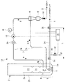
図1は、本発明の第1実施形態を示すガス化炉およびスラグ排出システムの概略構成図である。このスラグ排出システム1Aは、例えば石炭ガス化複合発電プラント(IGCC:Integrated Coal Gasification Combined Cycle)において、石炭(炭素含有固体燃料)をミル等で粉砕した微粉炭を空気や酸素等のガス化剤とともに炉内に投入して熱分解し、ガス化するガス化炉2(ガス化炉)に備えられている。なお、石炭ガス化炉に限らず、例えば間伐材、廃材木、流木、草類、廃棄物、汚泥、古タイヤ等のバイオマス燃料など、他の炭素含有固体燃料をガス化するガス化炉に置き換えてもよい。また、このスラグ排出システム1Aは、発電プラントに限らず、例えば化学プラントにおけるガス化炉等にも適用することができる。
Hereinafter, embodiments of the present invention will be described with reference to the drawings.
[First Embodiment]
FIG. 1 is a schematic configuration diagram of a gasification furnace and a slag discharge system showing a first embodiment of the present invention. This
ガス化炉2は、例えば加圧型噴流床式のガス化炉となっており、内側容器2aと、この内側容器2aの周囲を包囲する外側容器2bとを備えている。内側容器2aには、一部の微粉炭を燃焼させてガス化反応に必要な熱量を得るコンバスタ2cと、コンバスタ2cからの熱量を得て微粉炭をガス化するリダクタ2dとが上下二段に配置されている。
The
ガス化炉2の底部にはスラグホッパ5が設けられており、その内部にスラグ冷却水Wが貯留されている。ガス化炉2に投入された微粉炭中の灰分はコンバスタ2cで溶融後、液体状の溶融スラグとしてコンバスタ2c下部のスラグホール(非図示)から重力によりスラグホッパ5のスラグ冷却水W中に落下し、急冷されることにより固化して破砕され、荒い粒子状の固形のスラグSとなる。このスラグSはスラグ排出システム1Aによってガス化炉2の系外に排出される。スラグ排出システム1Aは、次のように構成されている。
A
スラグホッパ5にはスラグライン7が接続されている。このスラグライン7は、スラグホッパ5の底部5aから、破砕されたスラグSを排出するスラグ冷却水送水ライン7Aと、一端がスラグ分離装置10を介してスラグ冷却水送水ライン7Aに接続され、他端がスラグホッパ5に戻るように接続されたスラグ冷却水循環ライン7Bとを備えて構成されている。
A
スラグ冷却水送水ライン7Aの上流端はスラグ吸出口7pとされ、スラグホッパ5の底部5aよりも上方に離間して鉛直下方に向かって開口している。このスラグ吸出口7pからスラグホッパ5内の破砕されたスラグSとスラグ冷却水Wとの混合物であるスラグスラリーが吸い出される。スラグ冷却水送水ライン7Aの内部にはガス化炉2の運転圧力と同等の圧力が作用する。
The upstream end of the slag cooling
スラグライン7の途中に接続されたスラグ分離装置10は、スラグスラリーからスラグSを分離するものであり、例えば遠心分離装置(液体サイクロン等)が好適であるが、ストレーナやフィルタのような濾過式の分離手段を用いてもよい。スラグ吸出口7pから吸い出されたスラグスラリーは、スラグ冷却水送水ライン7Aを流れる水流によってスラグ分離装置10に移送される。
The
スラグ分離装置10の下部にはロックホッパ12と排出弁14とが接続されている。ロックホッパ12は、スラグ分離装置10にてスラグ冷却水Wから分離されたスラグSを所定量貯留するホッパであり、定期的に排出弁14が開かれてスラグの払い出しが行われる。払い出されたスラグSは図示しない運搬車両等によってガス化炉2の系外に搬出される。
A
スラグ冷却水循環ライン7Bにおいて、スラグ分離装置10の下流側には、圧力計16と循環ポンプ18と冷却器20とがこの順で接続されている。スラグ冷却水循環ライン7Bの下流端はスラグホッパ5におけるスラグ冷却水Wの浅層部に相当する高さに接続されている。即ち、スラグライン7は、スラグホッパ5から延出して再びスラグホッパ5の還流部5bに繋がるループ状の管路に構成されている。
In the slag cooling
スラグホッパ5の底部5a付近からは、ガス化炉2の外部に通じるスラグ払い出しライン24が所定の長さに亘って延出している。このスラグ払い出しライン24の、ガス化炉2への直近位置にスラグ払い出し弁26が設けられ、このスラグ払い出し弁26から下流側に所定の長さLを置いた位置にスラグ出口弁28が設けられている。上記の長さLとしては、後述するようにスラグ吸出口7pを閉塞させているスラグSを回収可能な内容積を弁26,28間のスラグ払い出しライン24に付与する長さとされる。スラグホッパ5の内部におけるスラグ払い出しライン24の開口端部の位置は、スラグ吸出口7pの近傍とするのが好ましい。スラグ払い出しライン24の下流端部は、例えば図示しないスラグ貯蔵タンクに接続されている。
From the vicinity of the bottom 5a of the
さらに、スラグ払い出しライン24には、スラグ払い出し弁26の直下流部付近に流体供給ライン30が接続され、この流体供給ライン30に流量調整弁32が設けられている。流体供給ライン30は、スラグ払い出しライン24内に流体SFを供給する管路である。流体SFとしては、空気や窒素ガス等の気体、あるいは水等の液体を用いることが考えられる。
Further, a
スラグ払い出し弁26、スラグ出口弁28、流量調整弁32は手動で開閉されるものでもよいが、本実施形態では制御部35によって電気的に開閉制御されるようになっている。さらに、循環ポンプ18も制御部35に制御されて作動するようになっている。
Although the
以上のように構成されたスラグ排出システム1Aは、通常運転モードと、スラグ払い出し運転モードの2つの運転モードを備えている。どちらの運転モードも、ガス化炉2の起動時および運転時に実行される。スラグ払い出し運転モードは、起動時および運転時にスラグ冷却水送水ライン7AがスラグSによって閉塞した時、または閉塞の予兆がある時に実行される運転モードである。
後に説明するように、スラグ排出システム1Aの起動時および運転時には、図2に示す圧力測定工程と、閉塞判定工程と、スラグ払い出し工程と、流体供給工程の4工程が実行される。
The
As will be described later, when the
制御部35は、通常運転モードでは、スラグ払い出し弁26とスラグ出口弁28と流量調整弁32を閉じて循環ポンプ18を作動させる。これにより、スラグ冷却水送水ライン7A内に、スラグ吸出口7pからスラグ分離装置10への水流が形成され、スラグホッパ5の底部5aに堆積したスラグスラリーがスラグ冷却水送水ライン7Aのスラグ吸出口7pから吸い出され、スラグ冷却水送水ライン7Aを経てスラグ分離装置10に送給される。
In the normal operation mode, the
スラグ分離装置10においてスラグスラリー中のスラグSはスラグ冷却水Wから分離されてロックホッパ12に貯留され、定期的に排出弁14から排出されてガス化炉2の系外に搬出される。そして、スラグSを除去されたスラグ冷却水Wのみがスラグ冷却水循環ライン7Bに流れて循環ポンプ18に吸入・吐出され、さらに冷却器20で所定の温度まで冷却されてから還流部5bを経てスラグホッパ5に還流する。還流したスラグ冷却水Wは再びスラグホッパ5の底部5aに堆積したスラグSと混合してスラグスラリーとなり、スラグ冷却水送水ライン7Aのスラグ吸出口7pから吸い出されてスラグ分離装置10に送給される。
In the
また、制御部35は、スラグ払い出し運転モードでは、スラグ払い出し弁26を所定時間(例えば数秒間)開いて閉じた後(スラグ払い出し工程)、スラグ出口弁28と流量調整弁32を開き、流体供給ライン30からスラグ払い出しライン24内に流体SFを供給する(流体供給工程)。この時、循環ポンプ18を停止させてスラグライン7(7A,7B)の水流を停止させる場合もある。
In the slag discharge operation mode, the
ガス化炉2の運転時にスラグ払い出し弁26が開かれることにより、ガス化炉2の内部圧力とスラグ払い出しライン24の内部圧力(例えば大気圧)との圧力差により、スラグホッパ5からスラグ払い出しライン24内に流れ込む流れが形成される。このため、スラグホッパ5に堆積したスラグSの少なくとも一部がスラグ払い出しライン24内に放出される。
When the
したがって、例えば起動時および運転時にスラグ吸出口7pがスラグSによって閉塞していたり、閉塞気味であったりしても、上記のようにスラグSの少なくとも一部をスラグ払い出しライン24へ放出することでスラグ吸出口7p付近におけるスラグSの密度を低下させ、スラグ吸出口7pからスラグスラリーを吸い込みやすくできる。これにより、スラグSによるスラグ吸出口7pの閉塞を抑制または解消し、ガス化炉2の起動および運転を順調に行うことができる。
Therefore, for example, even when the
その後、スラグ払い出し弁26が閉じられてスラグ出口弁28が開かれ、流体供給ライン30からスラグ払い出しライン24内に流体SFが送給されることにより、スラグ払い出しライン24中のスラグSが流体SFによって外部に流し出され、図示しないスラグ貯蔵タンク等に搬送される。したがって、スラグ払い出しライン24内に移送されたスラグSを確実に外部に払い出すことができる。また、スラグ払い出しライン24内に払い出し流体SFを供給することにより、スラグ払い出しライン24の内部圧力をスラグSの払い出しに適した圧力にすることができる。
Thereafter, the
本実施形態では、スラグSをスラグ払い出しライン24からスラグ貯蔵タンク等へ直接移送せずに、スラグ払い出しライン24に所定の長さLを付与し、その中にスラグSを一時的に貯留するようにしている。こうすることで、ガス化炉2の内圧と、スラグ貯蔵タンクの内圧(大気圧)との圧力差を緩和し、後から流れ込むスラグSの勢いを緩衝して、スラグ払い出しライン24に設けられる弁26,28や、スラグ貯留タンク等の払い出し用設備を破損から保護することができる。
In the present embodiment, the slag S is not directly transferred from the
また、このようにスラグSをスラグ払い出しライン24内に一時的に貯留するにあたり、スラグ払い出しライン24に所定の長さLを付与するとともに、その出口側にスラグ出口弁28を設けた。これにより、スラグ払い出しライン24に、スラグ吸出口7pを閉塞させているスラグSの全量を収容可能な容量を確保させることができ、スラグ払い出し弁26を開とするだけで、この所望量のスラグSを払い出し可能にして、スラグ吸出口7pの閉塞を確実に抑制または解消することができる。
Further, in order to temporarily store the slag S in the
スラグ払い出しライン24における流体供給ライン30の接続部の下流側にスラグ出口弁28を設け、このスラグ出口弁28を閉じておくことにより、ガス化炉2と流体供給ライン30との圧力差を低減し、ガス化炉2からスラグ払い出しライン24に移送されるスラグSの勢いを緩衝するバッファ機能を奏させることができ、払い出し用設備の破損等を防止することができる。
A
スラグ払い出し弁26とスラグ出口弁28との間に所定の距離Lを設け、この距離Lを、スラグ吸出口7pを閉塞させているスラグSを回収可能な内容積を弁26,28間のスラグ払い出しライン24に付与する長さとしたため、スラグ払い出し弁26が開かれた際に、スラグ払い出しライン24に流れ込むスラグSの勢いを緩衝するバッファ機能を増大させることができる。
A predetermined distance L is provided between the
通常運転モード、スラグ払い出し運転モードの切り替えは、オペレーターがスラグ吸出口7pの状態を監視しながら制御部35を操作することによって人為的に行ってもよいが、循環ポンプ18の吸い込み側の圧力を計測する圧力計16のデータを基にして制御部35に自動的に行わせることもできる。
Switching between the normal operation mode and the slag discharge operation mode may be performed manually by the operator operating the
つまり、ガス化炉2の起動時および運転中にスラグ吸出口7pが堆積したスラグS中に埋没したり、スラグ吸出口7p周辺のスラグ密度が高い状態になると、スラグ吸出口7pが閉塞または閉塞気味になり、スラグ吸出口7pの上流側に繋がっている循環ポンプ18の吸込み側の圧力(スラグ冷却水循環ライン7Bの圧力)が低くなる。
In other words, when the
この圧力データが圧力計16に計測されて制御部35に入力され(圧力測定工程)、制御部35はこの圧力データに基づいて、スラグ吸出口7pの閉塞状態を判定し(閉塞判定工程)、該圧力データが所定の閾値に達すると、制御部35は通常運転モードからスラグ払い出し運転モードに切り替えて上記のようにスラグホッパ5内のスラグSを一部払い出し(スラグ払い出し工程)、スラグSによるスラグ吸出口7pの閉塞を抑制または解消させる。
The pressure data is measured by the
このように、スラグ冷却水循環ライン7Bの循環ポンプ18の吸い込み側に圧力計16を設け、その圧力データを制御部35に入力して制御部35にスラグ払い出し弁26を開閉させるという簡素な構成により、スラグ吸出口7pの閉塞を自動的に抑制または解消することができる。
In this way, the
スラグ払い出し運転モードにおいて、流体供給ライン30からスラグ払い出しライン24内に流体SFとして空気や窒素ガス等の気体を供給する場合には、スラグ払い出し弁26とスラグ出口弁28とが開かれる前に予め流体供給ライン30からスラグ払い出しライン24内に流体SFを充填しておき(流体供給工程)、スラグ払い出しライン24の内部圧力をガス化炉2の内部圧力と大気圧との間の圧力に設定しておくのが好ましい。
In the slag discharge operation mode, when a gas such as air or nitrogen gas is supplied as the fluid SF from the
ガス化炉2の起動時および運転時にスラグ払い出し弁26を開くと、ガス化炉2の内部圧力と外部圧力(大気圧)との圧力差により、スラグホッパ5内のスラグSが勢い良くスラグ払い出しライン24に放出される。この勢いが強過ぎると、スラグ払い出しライン24の他端に設けられたスラグ出口弁28やスラグ貯留タンク等の払い出し用設備が破損する虞がある。
When the
上記のように、気体状の流体SFを予めスラグ払い出しライン24内に充填しておき、スラグ払い出しライン24の内部圧力をガス化炉2の内部圧力と大気圧との間の圧力に設定しておくことにより、ガス化炉2の内外の圧力差を小さくし、スラグ払い出し弁26を開いた時のスラグ放出速度を低下させて払い出し用設備の破損を防止することができる。但し、内外の圧力差をあまり小さくしてしまうと、スラグSを放出する勢いが低下してしまうため、この内外圧力差(流体SFの充填圧力)は適宜設定する必要がある。
As described above, the gaseous fluid SF is filled in the
あるいは、流体SFを水等の液体とし、この液体状の流体SFをスラグ払い出し運転モードにおいてスラグ払い出し弁26とスラグ出口弁28とが開く前に予め流体供給ライン30からスラグ払い出しライン24内に供給しておいてもよい。その供給量は、必ずしもスラグ払い出しライン24の内部を満たす量でなくてもよく、スラグ払い出しライン24の内部に液面が形成されればよい。
Alternatively, the fluid SF is a liquid such as water, and this liquid fluid SF is supplied from the
このように、液体状の流体SFを予めスラグ払い出しライン24内に供給しておけば、スラグ払い出し弁26の開弁と同時にスラグ払い出しライン24内に放出されるスラグSの放出速度が、液体状の流体SFの粘性によって減衰される。このため、スラグSの放出速度が過大になることによる払い出し用設備の破損を防止することができる。
In this way, if the liquid fluid SF is supplied into the
ところで、スラグ払い出し運転モードにおいては、スラグ冷却水送水ライン7AによるスラグSの吸い出しを停止させておくのが好ましい。具体的には、スラグ払い出し弁26を開く時にスラグ冷却水循環ライン7Bに設けられた循環ポンプ18を停止させる。
Incidentally, in the slag discharge operation mode, it is preferable to stop the suction of the slag S by the slag cooling
こうすれば、スラグ吸出口7pに吸着されてスラグ吸出口7pの内部に入れずに滞っていたスラグSがあったとしても、このスラグSは、スラグ冷却水送水ライン7Aによる吸い出しが停止することからスラグ吸出口7p付近に拘束されることがなくなり、スラグ払い出し運転の実行時にスラグ吸出口7pから離れてスラグ払い出しライン24に吸い込まれる。このため、スラグ吸出口7pの閉塞を確実に抑制または解消することができる。この効果は、スラグホッパ5の内部におけるスラグ払い出しライン24の開口端部の位置をスラグ吸出口7pの近傍とした場合に顕著になる。
In this way, even if there is slag S adsorbed by the
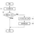
図2は、スラグ排出システム1Aの運転制御の流れを示すフローチャートである。この流れを説明すると、ガス化炉2の起動時、および運転開始後に、圧力計16により循環ポンプ18の吸い込み側の圧力を計測して制御部35に入力する圧力測定工程が実行される(ステップS1)。次に、制御部35において、入力された圧力データに基づきスラグ吸出口7pの閉塞状態を判定する閉塞判定工程が実行される(ステップS2)。
FIG. 2 is a flowchart showing a flow of operation control of the
閉塞判定工程S2においてスラグ吸出口7pが閉塞していないと判定された場合、即ち循環ポンプ18の吸い込み側の圧力が所定の閾値に達していない場合には、制御は元に戻り、圧力測定工程S1と閉塞判定工程S2とが反復される。また、閉塞判定工程S2においてスラグ吸出口7pが閉塞している、または閉塞の予兆があると判定された場合、即ち循環ポンプ18の吸い込み側の圧力が所定の閾値に達した場合には、スラグ払い出し工程が実行され(ステップS3)、流体供給工程が実行される(ステップS4)。
When it is determined that the
スラグ払い出し工程S3が実行されることにより、前述のようにスラグ吸出口7pの周囲近傍にあるスラグSがスラグ払い出しライン24から払い出され、スラグSによるスラグ吸出口7pの閉塞が回避もしくは解消される。
なお、スラグ払い出し工程S3と流体供給工程S4の前後関係はこのフローチャートの通りとは限らず、前後逆になったり、同時に行われたりすることもある。その後、制御は元に戻り、運転中は各ステップS1〜S4が反復される。
By executing the slag discharge step S3, as described above, the slag S in the vicinity of the periphery of the
The front-rear relationship between the slag discharge step S3 and the fluid supply step S4 is not limited to that shown in this flowchart, and may be reversed or performed simultaneously. Thereafter, the control returns to the original, and steps S1 to S4 are repeated during operation.
このように、スラグ冷却水循環ライン7Bの圧力を測定する圧力測定工程S1と、この圧力測定工程S1により測定した圧力データに基づいて、スラグ吸出口7pの閉塞状態を判定する閉塞判定工程S2と、をさらに備え、閉塞判定工程S2にてスラグ吸出口7pが閉塞したと判定された時、または閉塞の予兆がある時と判定された時に、スラグ払い出し工程S3を実行するようにした。
Thus, the pressure measurement step S1 for measuring the pressure of the slag cooling
この運転方法によれば、ガス化炉2の起動時、あるいは運転中に、スラグ吸出口7pがスラグS中に埋没したり、スラグ吸出口7p周辺のスラグ密度が高い状態になると、スラグ冷却水送水ライン7Aに通じるスラグ冷却水循環ライン7Bの圧力が低下するが、この圧力を測定する圧力測定工程S1を実行することで、スラグ吸出口7pが閉塞している、あるいは閉塞しつつあることを閉塞判定工程S2にて判定することができる。したがって、簡素な構成によりスラグ吸出口7pの閉塞を自動的に抑制または解消することができる。
According to this operation method, when the
ところで、流体供給工程S4をスラグ払い出し工程S3の後に実行することにより、スラグホッパ5からスラグ払い出しライン24に移送されたスラグSを流体SFによって確実に外部に排出することができる。
By the way, by performing the fluid supply step S4 after the slag discharge step S3, the slag S transferred from the
また、流体供給工程S4の実行時に、スラグ払い出し弁26の下流側に所定の距離Lを置いて設けられているスラグ出口弁28を閉じるようにしてもよい。これにより、所定の内容積を有するスラグ払い出しライン24の出口であるスラグ出口弁28が閉ざされた状態で、スラグ払い出しライン24の内部にスラグホッパ5からスラグSが払い出されるので、ガス化炉2とスラグ払い出しライン24との圧力差を低減し、ガス化炉2からスラグ払い出しライン24に移送されるスラグSの勢いを緩衝するバッファ機能を奏させて、払い出し用設備の破損等を防止することができる。
Further, when the fluid supply step S4 is performed, the
さらに、スラグ払い出し工程S3の実行時に、スラグ払い出し弁26を所定時間開いて閉じた後、流体供給工程S4を実行するようにしてもよい。これにより、払い出すスラグSの量をコントロールすることができる。
Furthermore, when the slag discharge step S3 is executed, the fluid supply step S4 may be executed after the
[第2実施形態]
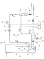
図3は、本発明の第2実施形態を示すガス化炉2およびスラグ排出システム1Bの概略構成図である。このスラグ排出システム1Bは、スラグ払い出しライン24に拡径部24aが設けられている点において第1実施形態のスラグ排出システム1Aと相違し、その他の点において同一である。したがって、同一構成の各部には同一符号を付して重複する説明は省略する。
[Second Embodiment]
FIG. 3 is a schematic configuration diagram of the
拡径部24aは、スラグ払い出しライン24の中間部の管路内径を部分的に拡大させたものである。この拡径部24aは、できるだけガス化炉2の近傍に設けるのが望ましい。
The
このような拡径部24aをスラグ払い出しライン24に設けることにより、スラグ払い出し弁26が開かれた時にスラグ払い出しライン24内に放出されるスラグSの放出速度(流速)が拡径部24aの部分で低下する。このため、前述のような払い出し用設備の破損を防止することができる。しかも、スラグ払い出しライン24の管路長あたりの内容積が増加するため、管路長を短縮してスラグ排出システム1Bをコンパクト化することができる。なお、拡径部24aをガス化炉2の近傍に設けることにより、スラグ払い出しライン24の内部がスラグSにより閉塞されることを防止することができる。
By providing such an
以上に説明したように、上記第1、第2実施形態に係るスラグ排出システム1A,1Bおよびこれを備えたガス化炉2によれば、簡素な構成により、ガス化炉2の底部からスラグSを吸い出すスラグ吸出口7pおよびスラグ冷却水送水ライン7AがスラグSによって閉塞することを抑制または解消し、ガス化炉2の起動および運転を順調に行うことができる。
As described above, according to the
なお、本発明は上記実施形態の構成のみに限定されるものではなく、適宜変更や改良を加えることができ、このように変更や改良を加えた実施形態も本発明の権利範囲に含まれるものとする。例えば、上記各実施形態における各構成部材の接続順序や設置位置等は適宜変更することが考えられる。 It should be noted that the present invention is not limited to the configuration of the above-described embodiment, and can be appropriately changed or improved. Embodiments with such changes and improvements are also included in the scope of the right of the present invention. And For example, it is conceivable to change the connection order, installation position, and the like of the constituent members in the above embodiments as appropriate.
例えば、上記実施形態では、スラグホッパ5の内部にスラグ吸出口7pおよびスラグ払い出しライン24が1つずつ設けられた例について説明したが、スラグ吸出口7pおよびスラグ払い出しライン24は複数設けられていてもよい。
For example, in the above-described embodiment, an example in which one
1A,1B スラグ排出システム
2 ガス化炉
5 スラグホッパ
5a スラグホッパの底部
7A スラグ冷却水送水ライン
7B スラグ冷却水循環ライン
7p スラグ吸出口
10 スラグ分離装置
16 圧力計
18 循環ポンプ
24 スラグ払い出しライン
24a 拡径部
26 スラグ払い出し弁
28 スラグ出口弁
30 流体供給ライン
35 制御部
S スラグ
SF 流体
S1 圧力測定工程
S2 閉塞判定工程
S3 スラグ払い出し工程
S4 流体供給工程
W スラグ冷却水
1A, 1B
Claims (18)
前記スラグホッパの底部に堆積する前記スラグと前記スラグ冷却水とを吸い出すスラグ吸出口と、
前記スラグ吸出口から吸い出された前記スラグと前記スラグ冷却水とをスラグ分離装置に送り、該スラグ分離装置にて前記スラグを分離させるスラグ冷却水送水ラインと、
前記スラグホッパの底部付近から延出して前記ガス化炉の外部に通じるスラグ払い出しラインと、
前記スラグ払い出しラインに設けられたスラグ払い出し弁と、
を備えてなるスラグ排出システム。 A slag hopper provided at the bottom of a gasification furnace for gasifying the carbon-containing solid fuel, receiving slag generated from the carbon-containing solid fuel, and storing slag cooling water for rapidly cooling the slag;
A slag suction port for sucking out the slag and the slag cooling water accumulated at the bottom of the slag hopper;
A slag cooling water feed line that sends the slag sucked out from the slag suction port and the slag cooling water to a slag separator, and separates the slag by the slag separator;
A slag discharge line extending from near the bottom of the slag hopper and leading to the outside of the gasification furnace;
A slag discharge valve provided in the slag discharge line;
A slag discharge system comprising:
前記スラグ冷却水循環ラインに接続されている循環ポンプと、
前記循環ポンプの吸い込み側の圧力を計測する圧力計と、
前記圧力計により計測された圧力データを入力され、該圧力データが所定の閾値に達した時に、前記スラグ払い出し弁の開閉制御を行う制御部と、をさらに備えた請求項1に記載のスラグ排出システム。 A slag cooling water circulation line that is connected to the slag cooling water feed line via the slag separation device and circulates the slag cooling water separated from the slag by the slag separation device to the slag hopper;
A circulation pump connected to the slag cooling water circulation line;
A pressure gauge for measuring the pressure on the suction side of the circulation pump;
The slag discharge according to claim 1, further comprising: a control unit that receives pressure data measured by the pressure gauge and performs opening / closing control of the slag discharge valve when the pressure data reaches a predetermined threshold value. system.
前記スラグ吸出口が前記スラグによって閉塞した時、または閉塞の予兆がある時に、前記スラグホッパから外部に延出させたスラグ払い出しラインから前記スラグを払い出すスラグ払い出し工程を備えるスラグ排出システムの運転方法。 A method for operating a slag discharge system that sucks slag that has fallen into a slag hopper at the bottom of a gasification furnace that gasifies carbon-containing solid fuel together with slag cooling water from a slag suction port and sends the slag to a slag separator through a slag cooling water feed line ,
An operation method of a slag discharge system comprising a slag discharge step of discharging the slag from a slag discharge line extended to the outside from the slag hopper when the slag suction port is blocked by the slag or when there is a sign of blockage.
前記スラグ冷却水循環ラインの圧力を測定する圧力測定工程と、
前記圧力測定工程により測定した圧力データに基づいて、前記スラグ吸出口の閉塞状態を判定する閉塞判定工程と、をさらに備え、
前記閉塞判定工程にて前記スラグ吸出口が閉塞したと判定された時、または閉塞の予兆がある時と判定された時に、前記スラグ払い出し工程を実行する請求項10に記載のスラグ排出システムの運転方法。 A slag discharge system further comprising a slag cooling water circulation line that is connected to the slag cooling water supply line via the slag separation device and circulates the slag cooling water separated from the slag by the slag separation device to the slag hopper. In the driving method of
A pressure measuring step of measuring the pressure of the slag cooling water circulation line;
A blockage determination step of determining a blockage state of the slag suction port based on the pressure data measured by the pressure measurement step,
The operation of the slag discharge system according to claim 10, wherein the slag discharge system is executed when it is determined that the slag intake port is blocked in the blockage determination step or when there is a sign of blockage. Method.
Priority Applications (1)
| Application Number | Priority Date | Filing Date | Title |
|---|---|---|---|
| JP2016082862A JP6685816B2 (en) | 2016-04-18 | 2016-04-18 | Slag discharge system, gasifier equipped with the same, and method of operating slag discharge system |
Applications Claiming Priority (1)
| Application Number | Priority Date | Filing Date | Title |
|---|---|---|---|
| JP2016082862A JP6685816B2 (en) | 2016-04-18 | 2016-04-18 | Slag discharge system, gasifier equipped with the same, and method of operating slag discharge system |
Publications (2)
| Publication Number | Publication Date |
|---|---|
| JP2017193600A true JP2017193600A (en) | 2017-10-26 |
| JP6685816B2 JP6685816B2 (en) | 2020-04-22 |
Family
ID=60155104
Family Applications (1)
| Application Number | Title | Priority Date | Filing Date |
|---|---|---|---|
| JP2016082862A Active JP6685816B2 (en) | 2016-04-18 | 2016-04-18 | Slag discharge system, gasifier equipped with the same, and method of operating slag discharge system |
Country Status (1)
| Country | Link |
|---|---|
| JP (1) | JP6685816B2 (en) |
Citations (6)
| Publication number | Priority date | Publication date | Assignee | Title |
|---|---|---|---|---|
| JPS50129605A (en) * | 1974-03-18 | 1975-10-14 | ||
| JPH08134472A (en) * | 1994-11-10 | 1996-05-28 | Babcock Hitachi Kk | Airflow layer gasifier |
| JPH11140464A (en) * | 1997-11-05 | 1999-05-25 | Babcock Hitachi Kk | Coal gasifier and slag discharge method of the same |
| WO2011040112A1 (en) * | 2009-09-30 | 2011-04-07 | 三菱重工業株式会社 | Slag discharge system |
| JP2013056972A (en) * | 2011-09-07 | 2013-03-28 | Mitsubishi Heavy Ind Ltd | Slag discharge system, gasification apparatus, and gasification power generator |
| JP2013112734A (en) * | 2011-11-28 | 2013-06-10 | Mitsubishi Heavy Ind Ltd | Slag discharge system |
-
2016
- 2016-04-18 JP JP2016082862A patent/JP6685816B2/en active Active
Patent Citations (6)
| Publication number | Priority date | Publication date | Assignee | Title |
|---|---|---|---|---|
| JPS50129605A (en) * | 1974-03-18 | 1975-10-14 | ||
| JPH08134472A (en) * | 1994-11-10 | 1996-05-28 | Babcock Hitachi Kk | Airflow layer gasifier |
| JPH11140464A (en) * | 1997-11-05 | 1999-05-25 | Babcock Hitachi Kk | Coal gasifier and slag discharge method of the same |
| WO2011040112A1 (en) * | 2009-09-30 | 2011-04-07 | 三菱重工業株式会社 | Slag discharge system |
| JP2013056972A (en) * | 2011-09-07 | 2013-03-28 | Mitsubishi Heavy Ind Ltd | Slag discharge system, gasification apparatus, and gasification power generator |
| JP2013112734A (en) * | 2011-11-28 | 2013-06-10 | Mitsubishi Heavy Ind Ltd | Slag discharge system |
Also Published As
| Publication number | Publication date |
|---|---|
| JP6685816B2 (en) | 2020-04-22 |
Similar Documents
| Publication | Publication Date | Title |
|---|---|---|
| JP5743093B2 (en) | Slag discharge system, gasifier, and gas generator | |
| JP6682280B2 (en) | Slag discharge system and gasifier | |
| JP5484850B2 (en) | Slag discharge system | |
| JP2019142701A (en) | Powder supply hopper pressure device, gasification furnace equipment and gasification combined power generation equipment, and method of controlling powder supply hopper pressure device | |
| JP6732908B2 (en) | Slag discharge system, gasifier equipped with the same, and method of operating slag discharge system | |
| JP5721612B2 (en) | Slag discharge system | |
| JP4291670B2 (en) | Waste supply device | |
| JP2018111759A (en) | Slag discharge system, gasification furnace equipment, gasification combined electric power generation equipment and method for operating the slag discharge system | |
| JP6685816B2 (en) | Slag discharge system, gasifier equipped with the same, and method of operating slag discharge system | |
| JP4422280B2 (en) | Precision dust removal equipment ash treatment apparatus and ash treatment method therefor | |
| US10927316B2 (en) | Char discharge unit, char recovery unit including char discharge unit, char discharge method, and integrated gasification combined cycle | |
| JP2013082830A (en) | Slurry conveying device | |
| US11292976B2 (en) | Slag discharge system, gasifier, and slag filtration method | |
| JP5535868B2 (en) | Slag discharge system and method of operating slag discharge system | |
| US20080115479A1 (en) | Pressurized coal gasifier and coal gasification combined cycle power plant | |
| JPH06506531A (en) | Ash discharge method and equipment | |
| JP3760538B2 (en) | In-bed pressure detector for pressurized fluidized bed boiler | |
| JP2012087999A (en) | Slag discharge system and method for operating the same | |
| JPH0711262A (en) | Pulverized coal gasifier | |
| JPH09166303A (en) | Fly ash treatment device for pressurized fluidized bed boiler |
Legal Events
| Date | Code | Title | Description |
|---|---|---|---|
| A625 | Written request for application examination (by other person) |
Free format text: JAPANESE INTERMEDIATE CODE: A625 Effective date: 20190315 |
|
| A977 | Report on retrieval |
Free format text: JAPANESE INTERMEDIATE CODE: A971007 Effective date: 20190807 |
|
| A131 | Notification of reasons for refusal |
Free format text: JAPANESE INTERMEDIATE CODE: A131 Effective date: 20190813 |
|
| A521 | Request for written amendment filed |
Free format text: JAPANESE INTERMEDIATE CODE: A523 Effective date: 20191015 |
|
| A02 | Decision of refusal |
Free format text: JAPANESE INTERMEDIATE CODE: A02 Effective date: 20191105 |
|
| A521 | Request for written amendment filed |
Free format text: JAPANESE INTERMEDIATE CODE: A523 Effective date: 20200205 |
|
| A911 | Transfer to examiner for re-examination before appeal (zenchi) |
Free format text: JAPANESE INTERMEDIATE CODE: A911 Effective date: 20200214 |
|
| TRDD | Decision of grant or rejection written | ||
| A01 | Written decision to grant a patent or to grant a registration (utility model) |
Free format text: JAPANESE INTERMEDIATE CODE: A01 Effective date: 20200303 |
|
| A61 | First payment of annual fees (during grant procedure) |
Free format text: JAPANESE INTERMEDIATE CODE: A61 Effective date: 20200401 |
|
| R150 | Certificate of patent or registration of utility model |
Ref document number: 6685816 Country of ref document: JP Free format text: JAPANESE INTERMEDIATE CODE: R150 |
|
| S533 | Written request for registration of change of name |
Free format text: JAPANESE INTERMEDIATE CODE: R313533 |
|
| R350 | Written notification of registration of transfer |
Free format text: JAPANESE INTERMEDIATE CODE: R350 |