JP2017193880A - Earth anchor and fixation method of earth anchor - Google Patents
Earth anchor and fixation method of earth anchor Download PDFInfo
- Publication number
- JP2017193880A JP2017193880A JP2016085146A JP2016085146A JP2017193880A JP 2017193880 A JP2017193880 A JP 2017193880A JP 2016085146 A JP2016085146 A JP 2016085146A JP 2016085146 A JP2016085146 A JP 2016085146A JP 2017193880 A JP2017193880 A JP 2017193880A
- Authority
- JP
- Japan
- Prior art keywords
- tension rod
- end side
- fixing
- rod
- earth anchor
- Prior art date
- Legal status (The legal status is an assumption and is not a legal conclusion. Google has not performed a legal analysis and makes no representation as to the accuracy of the status listed.)
- Pending
Links
- 238000000034 method Methods 0.000 title claims abstract description 36
- 230000002093 peripheral effect Effects 0.000 claims abstract description 15
- 238000009412 basement excavation Methods 0.000 claims description 33
- 210000001015 abdomen Anatomy 0.000 claims description 6
- 238000003780 insertion Methods 0.000 claims description 5
- 230000037431 insertion Effects 0.000 claims description 5
- 239000002184 metal Substances 0.000 description 13
- 238000005553 drilling Methods 0.000 description 10
- 239000002775 capsule Substances 0.000 description 9
- 239000004570 mortar (masonry) Substances 0.000 description 9
- 239000002689 soil Substances 0.000 description 7
- 238000010586 diagram Methods 0.000 description 5
- 230000000452 restraining effect Effects 0.000 description 5
- 238000010276 construction Methods 0.000 description 4
- 230000007774 longterm Effects 0.000 description 4
- 230000001105 regulatory effect Effects 0.000 description 4
- 238000006073 displacement reaction Methods 0.000 description 2
- 230000003014 reinforcing effect Effects 0.000 description 2
- 239000011435 rock Substances 0.000 description 2
- 238000003466 welding Methods 0.000 description 2
- 230000003187 abdominal effect Effects 0.000 description 1
- 238000004873 anchoring Methods 0.000 description 1
- 238000002347 injection Methods 0.000 description 1
- 239000007924 injection Substances 0.000 description 1
- JEIPFZHSYJVQDO-UHFFFAOYSA-N iron(III) oxide Inorganic materials O=[Fe]O[Fe]=O JEIPFZHSYJVQDO-UHFFFAOYSA-N 0.000 description 1
- 238000005259 measurement Methods 0.000 description 1
- 230000002265 prevention Effects 0.000 description 1
- 239000011347 resin Substances 0.000 description 1
- 229920005989 resin Polymers 0.000 description 1
- 230000000087 stabilizing effect Effects 0.000 description 1
Images

Landscapes
- Piles And Underground Anchors (AREA)
Abstract
Description
本発明は、盛土や切土の法面が地盤の緩み等によって崩れないように補強を行う際等に使用されるアースアンカー及びアースアンカーの定着方法に関する。 The present invention relates to an earth anchor and a method for fixing an earth anchor that are used when reinforcing a cut slope or a cut slope so as not to collapse due to loose ground.
従来から、宅地造成等に伴って、盛土や切土によって形成された人工的斜面(法面)が、地震等による地盤の緩み等によって崩壊することを防止するために、法面を安定化するための様々な手法が提案されている。このような法面の安定化のための手法としては、例えば、アースアンカー工法が知られている。 Conventionally, in order to prevent artificial slopes (slopes) formed by embankments and cuts from collapsing due to loosening of the ground due to earthquakes, etc., along with residential land development, etc., stabilize the slopes Various techniques have been proposed for this purpose. As a method for stabilizing such a slope, for example, an earth anchor method is known.
このアースアンカー工法は、例えば、ワイヤロープ等を係留して落石防護網を地盤にしっかりと固定させることによって法面を安定化させたり、或いは、擁壁を地盤にしっかりと固定させるため等に用いられるものである。一般的なアースアンカー工法では、例えば、法面にボーリングマシンによって複数の掘削孔を形成し、これらの掘削孔にアースアンカーをそれぞれ挿入して地盤に定着させた後、地盤表面に露出したそれぞれのアースアンカーの頭部に定着金具をそれぞれ取り付けて、最後に、それぞれの定着金具同士を互いにワイヤロープ等で連結させて落石防護網を地盤に固定することによって法面を安定化させている。 This earth anchor method is used, for example, to stabilize the slope by anchoring a wire rope or the like and firmly fixing the falling rock protection net to the ground, or to fix the retaining wall firmly to the ground, etc. It is what In a general earth anchor construction method, for example, a plurality of excavation holes are formed on a slope by a boring machine, and earth anchors are respectively inserted into these excavation holes to be fixed on the ground, and then each exposed on the ground surface. Fixing brackets are attached to the heads of the earth anchors, and finally, the fixing surfaces are stabilized by connecting the fixing brackets to each other with a wire rope or the like and fixing the falling rock protection net to the ground.
このようなアースアンカー工法に用いるアースアンカーとして、本発明者らは、土壌の性状に拘わらず確実に地盤に定着させることができ、施工も簡易且つ迅速に行うことができるアースアンカーを提案している(例えば、特許文献1参照)。特許文献1のアースアンカーは、掘削孔内に挿入される所要長さの引っ張りロッドと、この引っ張りロッドの先端部に設けられた取付部と、前記引っ張りロッドの円周方向に等配され、前記取付部にそれぞれ一端部が回動可能に取着されて、引っ張りロッドに対して拡開する複数本の棒状定着部材と、前記引っ張りロッド先端部の取付部に設けられ、棒状定着部材の拡開動作を規制するストッパ部と、前記引っ張りロッドに固設され、前記棒状定着部材を、引っ張りロッドに対して拡開する方向へ付勢する弾発手段と、この弾発手段の付勢力に抗して、前記棒状定着部材が前記引っ張りロッドに対して拡開するのを阻止し棒状定着部材を引っ張りロッドに対して閉じた状態に拘束する拘止手段と、この拘止手段による前記棒状定着部材の拘束状態を解除して、前記弾発手段の付勢力によって棒状定着部材を一気に拡開させる拘束解除手段とを備えている。
As an earth anchor used for such an earth anchor construction method, the present inventors have proposed an earth anchor that can be firmly fixed on the ground regardless of the properties of the soil and can be easily and quickly constructed. (For example, refer to Patent Document 1). The ground anchor of
このような特許文献1のアースアンカーを用いた工法では、棒状定着部材の側を前方にして引っ張りロッドを掘削孔内に挿入した後、拘束解除手段によって拘止手段による棒状定着部材の拘束状態を解除すると、弾発手段によって複数本の棒状定着部材が拡開する方向へ付勢され、各棒状定着部材の先端部が掘削孔の周壁面に押し付けられ突き刺さる。これと同時もしくはその直後に、引っ張りロッドを地表側に引っ張ると、各先端部が掘削孔の周壁面に突き刺さった複数本の棒状定着部材が大きく拡開することにより、アースアンカーを地盤に簡易且つ迅速に定着させることができる。
In such a construction method using the earth anchor of
しかしながら、特許文献1のアースアンカーでは、棒状定着部材を拡開させるために、板バネ等の弾発手段の付勢力を用いているので、長期耐久性が低いという問題がある。
However, the earth anchor of
本発明は、上記のような課題に鑑みてなされたものであって、長期耐久性に優れており、簡易且つ強固に地盤に定着させることができるアースアンカー及びアースアンカーの定着方法を提供することを目的とする。 The present invention has been made in view of the above-described problems, and provides an earth anchor and a method for fixing an earth anchor that are excellent in long-term durability and can be easily and firmly fixed on the ground. With the goal.
上記目的を達成するために、本発明に係るアースアンカーは、所定の長さを有し、外周面に雄ねじが形成されている引張りロッドと、前記引張りロッドの先端側に一端側がそれぞれ回動可能に取り付けられ、他端側がそれぞれ前記引張りロッドに対して近接している閉鎖状態から前記引張りロッドに対して離隔する方向へ拡翼し、前記他端側の先端部は、前記閉鎖状態において前記引張りロッドと対向する腹部側よりも反対側の背部側の方が長尺になるように傾斜面が形成されている複数の定着部材と、前記定着部材が所定角度以上は拡翼しないように規制するストッパ部と、前記引張りロッドの径よりも大径の貫通孔を有するように中空状に形成され、前記引張りロッドを前記貫通孔内に挿通させた状態で前記引張りロッドの軸方向に移動可能な楔管と、内周面に前記引張りロッドの前記雄ねじと螺合可能な雌ねじを有し、前記引張りロッドに対してねじ込まれることにより前記引張りロッドの軸方向の先端側へ移動して、前記楔管の後端側から前記楔管を前記複数の定着部材に対して押し込むことで、前記複数の定着部材を拡翼させるねじ管と、を備えることを特徴としている。 In order to achieve the above object, an earth anchor according to the present invention has a predetermined length, a tension rod having a male thread formed on the outer peripheral surface, and one end side of the tension rod can be turned at the tip side. The other end side is expanded in a direction away from the tension rod from the closed state in which the other end side is close to the tension rod, and the tip end on the other end side is the tension member in the closed state. A plurality of fixing members having inclined surfaces formed so that the back side opposite to the abdomen opposite to the rod is longer, and the fixing member is regulated not to expand the wings beyond a predetermined angle. It is formed in a hollow shape so as to have a stopper portion and a through hole having a diameter larger than the diameter of the tension rod, and moves in the axial direction of the tension rod while the tension rod is inserted into the through hole. An active wedge tube, and an internal thread having an internal thread that can be screwed to the external thread of the tension rod, and moving to the distal end side in the axial direction of the tension rod by being screwed into the tension rod; And a screw tube that expands the plurality of fixing members by pushing the wedge tube into the plurality of fixing members from a rear end side of the wedge tube.
また、本発明に係るアースアンカーは、前記引張りロッドを後端側へ瞬間的に移動させるための逆打撃を加える逆打撃手段を備えることを特徴としている。 The earth anchor according to the present invention is characterized by comprising reverse hitting means for applying a reverse hit for instantaneously moving the tension rod toward the rear end side.
また、本発明に係るアースアンカーの定着方法は、地盤に掘削孔を形成する掘削工程と、前記アースアンカーを前記掘削孔内に前記定着部材を前記閉鎖状態で、前記引張りロッドの先端側から挿入する挿入工程と、前記楔管の先端が前記定着部材の前記傾斜面と当接するように前記楔管を前記引張りロッドに差し込む差込工程と、前記ねじ管の位置が前記楔管を前記複数の定着部材に対して押し込む直前の初期位置にくるように、前記引張りロッドの前記雄ねじに前記雌ねじを螺合させる初期位置設定工程と、前記引張りロッドを地表側に引張ると共に、前記ねじ管を前記引張りロッドに対してねじ込むことにより前記引張りロッドの軸方向の先端側へ移動させ、前記楔管の後端側から前記楔管を前記複数の定着部材に対して押し込むことで、前記複数の定着部材を拡翼させて、前記アースアンカーを前記地盤に定着させる定着工程と、を含むことを特徴としている。 The ground anchor fixing method according to the present invention includes a drilling step of forming a drilling hole in the ground, and inserting the ground anchor into the drilling hole from the distal end side of the tension rod in the closed state. An inserting step for inserting the wedge tube into the pulling rod so that a tip of the wedge tube is in contact with the inclined surface of the fixing member, and a position of the screw tube is the plurality of wedge tubes. An initial position setting step of screwing the female screw into the male screw of the pulling rod so as to be in an initial position immediately before being pushed into the fixing member; pulling the pulling rod toward the ground surface; and pulling the screw tube By screwing into the rod, the pulling rod is moved to the tip end side in the axial direction, and the wedge tube is pushed into the plurality of fixing members from the rear end side of the wedge tube. Said a plurality of fixing members is 拡翼 is characterized by comprising a fixing step of fixing the ground anchor into the ground.
また、本発明に係るアースアンカーの定着方法は、前記定着工程では、前記定着部材が一定の角度まで拡翼した後は、前記逆打撃手段によって前記引張りロッドを後端側へ瞬間的に移動させるための逆打撃を加えることを特徴としている。 In the fixing method of the earth anchor according to the present invention, in the fixing step, after the fixing member expands the blade to a certain angle, the tension rod is instantaneously moved to the rear end side by the reverse striking means. It is characterized by adding a reverse blow for.
本発明に係るアースアンカーの定着方法によれば、所定の長さを有し、外周面に雄ねじが形成されている引張りロッドと、前記引張りロッドの先端側に一端側がそれぞれ回動可能に取り付けられ、他端側がそれぞれ前記引張りロッドに対して近接している閉鎖状態から前記引張りロッドに対して離隔する方向へ拡翼する複数の定着部材と、前記引張りロッドの径よりも大径の貫通孔を有するように中空状に形成され、前記引張りロッドを前記貫通孔内に挿通させた状態で前記引張りロッドの軸方向に移動可能な楔管と、内周面に前記引張りロッドの前記雄ねじと螺合可能な雌ねじを有し、前記引張りロッドに対してねじ込まれることにより前記引張りロッドの軸方向の先端側へ移動して、前記楔管の後端側から前記楔管を前記複数の定着部材に対して押し込むことで、前記複数の定着部材を拡翼させるねじ管とを備えているので、地盤に形成した掘削孔内に前記定着部材を閉鎖状態で、前記引張りロッドの先端側から挿入し、前記ねじ管を前記引張りロッドに対してねじ込んで、前記楔管を前記複数の定着部材に対して押し込むことによって、前記複数の定着部材を拡翼させて地盤に定着させることができる。このように本発明に係るアースアンカーでは、定着部材を拡翼させるためにバネ等の部材を用いる必要がなく、ねじ管を引張りロッドに対してねじ込んで、楔管を前記複数の定着部材に対して押し込むことによって、定着部材を拡翼させることができるので、長期耐久性に優れており、簡易且つ強固に地盤に定着させることができる。また、本発明に係るアースアンカーは、定着部材が所定角度以上は拡翼しないように規制するストッパ部を備えているので、地盤への定着を安定的に行うことができると共に、定着部材が必要以上に拡翼して破損すること等を防止することができる。 According to the ground anchor fixing method of the present invention, a tension rod having a predetermined length and having an external thread formed on the outer peripheral surface, and one end side of the tension rod are rotatably attached to the distal end side of the tension rod. A plurality of fixing members that expand in a direction away from the tension rod from a closed state in which the other end side is close to the tension rod, and a through hole having a diameter larger than the diameter of the tension rod. A wedge tube which is formed in a hollow shape so as to be movable and is movable in the axial direction of the tension rod in a state where the tension rod is inserted into the through-hole, and is screwed with the male screw of the tension rod on an inner peripheral surface A plurality of fixing members, each of which has a possible internal thread and is moved into the axial front end side of the pulling rod by being screwed into the pulling rod, so that the wedge pipe is moved from the rear end side of the wedge pipe. Since it is provided with a screw tube that expands the plurality of fixing members by pushing in, the fixing member is inserted into the excavation hole formed in the ground in a closed state from the tip side of the tension rod, The plurality of fixing members can be expanded and fixed on the ground by screwing the threaded tube into the pulling rod and pushing the wedge tube into the plurality of fixing members. As described above, in the earth anchor according to the present invention, it is not necessary to use a member such as a spring in order to expand the fixing member, and the screw tube is screwed into the pulling rod and the wedge tube is attached to the plurality of fixing members. Since the fixing member can be expanded by pushing it in, the long-term durability is excellent, and the fixing member can be fixed to the ground easily and firmly. In addition, since the earth anchor according to the present invention includes a stopper portion that regulates the fixing member so as not to expand the blade beyond a predetermined angle, the fixing to the ground can be stably performed and the fixing member is necessary. It is possible to prevent the blades from expanding and being damaged.
また、本発明に係るアースアンカーによれば、引張りロッドを後端側へ瞬間的に移動させるための逆打撃を加える逆打撃手段を備えているので、定着部材が大きく拡翼する拡翼後期の段階において、地盤中の土等からの抵抗で、楔管を定着部材に対して押し込むことが困難な場合等に、逆打撃手段によって引張りロッドに対して逆打撃を加えることで、引張りロッドを後端側へ瞬間的に移動させることにより、容易にねじ管を引張りロッドに対してねじ込んで、楔管を定着部材に対して押し込むことができる。これにより、本発明に係るアースアンカーでは、ストッパ部によって規制される段階まで定着部材を確実且つ効率的に拡翼させることができる。 In addition, according to the earth anchor according to the present invention, since the reverse impact means for applying the reverse impact for instantaneously moving the tension rod to the rear end side is provided, the fixing member is greatly expanded in the latter stage of the blade expansion. In the stage, when it is difficult to push the wedge tube against the fixing member due to resistance from soil etc. in the ground, reverse pulling is applied to the pulling rod by the reverse striking means, and the pulling rod is moved backward. By instantaneously moving to the end side, the screw tube can be easily screwed into the pulling rod and the wedge tube can be pushed into the fixing member. Thereby, in the earth anchor which concerns on this invention, a fixing member can be reliably and efficiently expanded to the stage regulated by a stopper part.
また、本発明に係るアースアンカーの定着方法によれば、地盤に掘削孔を形成し、アースアンカーを前記掘削孔内に前記定着部材を前記閉鎖状態で、前記引張りロッドの先端側から挿入し、前記楔管の先端が前記定着部材の前記傾斜面と当接するように前記楔管を前記引張りロッドに差し込み、前記ねじ管の位置が前記楔管を前記複数の定着部材に対して押し込む直前の初期位置にくるように、前記引張りロッドの前記雄ねじに前記雌ねじを螺合させ、前記引張りロッドを地表側に引張ると共に、前記ねじ管を前記引張りロッドに対してねじ込むことにより前記引張りロッドの軸方向の先端側へ移動させ、前記楔管の後端側から前記楔管を前記複数の定着部材に対して押し込むことで、前記複数の定着部材を拡翼させて、前記アースアンカーを前記地盤に定着させるので、定着部材を拡翼させるためにバネ等の部材を用いる必要がなく、ねじ管を引張りロッドに対してねじ込んで、楔管を前記複数の定着部材に対して押し込むことによって、定着部材を拡翼させることができるため、長期耐久性に優れており、簡易且つ強固に地盤に定着させることができる。また、本発明に係るアースアンカーの定着方法では、ねじ管を引張りロッドに対してねじ込んで、楔管を前記複数の定着部材に対して押し込むだけでなく、同時に引張りロッドを地表側に引張るので、定着部材を地盤中の土等からの抵抗を軽減させるような所望の軌跡に沿って効率的に拡翼させることができる。また、本発明に係るアースアンカーの定着方法では、ねじ管を引張りロッドに対してねじ込んで、楔管を複数の定着部材に対して押し込むことによって、定着部材を拡翼させて、アースアンカーを地盤に定着させるので、掘削孔に注入されるモルタルが固まるまで待つ必要がなく、工期を短縮することができる。 Further, according to the fixing method of the earth anchor according to the present invention, an excavation hole is formed in the ground, and the earth anchor is inserted into the excavation hole from the distal end side of the tension rod in the closed state, The wedge tube is inserted into the pulling rod so that the tip of the wedge tube is in contact with the inclined surface of the fixing member, and the position of the screw tube is an initial stage immediately before the wedge tube is pushed into the plurality of fixing members. The female screw is screwed onto the male screw of the pulling rod so as to be in the position, the pulling rod is pulled to the ground surface side, and the screw tube is screwed into the pulling rod so as to move in the axial direction of the pulling rod. The ground anchors are moved to the front end side, and the plurality of fixing members are expanded by pushing the wedge pipes into the plurality of fixing members from the rear end side of the wedge pipes. Since fixing is performed on the ground, it is not necessary to use a member such as a spring to expand the fixing member, and by screwing the screw tube into the pulling rod and pushing the wedge tube into the plurality of fixing members. Since the fixing member can be expanded, it has excellent long-term durability and can be fixed to the ground easily and firmly. Further, in the fixing method of the earth anchor according to the present invention, not only the screw tube is screwed into the tension rod and the wedge tube is pushed into the plurality of fixing members, but at the same time, the tension rod is pulled to the ground surface side, It is possible to efficiently expand the fixing member along a desired trajectory that reduces resistance from soil or the like in the ground. In the earth anchor fixing method according to the present invention, the fixing member is expanded by screwing the screw tube into the pulling rod and pushing the wedge tube into the plurality of fixing members. Therefore, it is not necessary to wait until the mortar injected into the excavation hole is hardened, and the construction period can be shortened.
また、本発明に係るアースアンカーの定着方法によれば、定着部材が一定の角度まで拡翼した後は、逆打撃手段によって引張りロッドを後端側へ瞬間的に移動させるための逆打撃を加えるので、地盤中の土等からの抵抗で、楔管を定着部材に対して押し込むことが困難な場合(定着部材を地盤中に突き刺さらせ拡翼させていくことが困難な場合)等でも、引張りロッドを後端側へ瞬間的に移動させることにより、容易にねじ管を引張りロッドに対してねじ込んで、楔管を定着部材に対して押し込むことができ、定着部材を確実且つ効率的に拡翼させて地盤に定着させることができる。 Further, according to the earth anchor fixing method of the present invention, after the fixing member has expanded the blade to a certain angle, a reverse impact is applied to instantaneously move the tension rod to the rear end side by the reverse impact means. Therefore, even when it is difficult to push the wedge tube into the fixing member due to resistance from soil etc. in the ground (when it is difficult to pierce the fixing member into the ground and expand the wing), By momentarily moving the tension rod to the rear end side, the screw tube can be easily screwed into the tension rod and the wedge tube can be pushed into the fixing member, so that the fixing member can be expanded reliably and efficiently. Wings can be fixed on the ground.
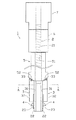
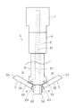
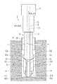
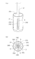
以下、本発明の実施形態に係るアースアンカー1について、図面を参照しつつ説明する。アースアンカー1は、例えば、盛土や切土の法面が地盤の緩み等によって崩れないように補強を行う際等に使用されるものであって、図1に示すように、所定の長さを有し、外周面に雄ねじ21が形成されている引張りロッド2と、引張りロッド2の先端側に一端側がそれぞれ回動可能に取り付けられていることによって拡翼可能な複数の定着部材3と、定着部材3が所定角度以上は拡翼しないように規制するストッパ部4と、引張りロッド2の径よりも大径の貫通孔51を有するように中空状に形成されている楔管5と、内周面に引張りロッド2の雄ねじ21と螺号可能な雌ねじ(不図示)を有するねじ管6等を備えている。また、本実施形態に係るアースアンカー1では、地盤へ定着させる際に、引張りロッド2を後端側へ瞬間的に移動させるための逆打撃を加える逆打撃手段としての機能(バックハンマー機能)を有するボーリングマシン7を備えている。
Hereinafter, an
引張りロッド2は、後述する掘削孔内に挿入されるものであって、例えば、長尺な円柱状に形成されており、その全長は挿入される掘削孔の長さに対応するよう形成されている。この引張りロッド2では、図3に示すように、複数の定着部材3を取り付け易いように、先端側の断面は一辺が円柱状に形成されている部分の径と略同じ長さを有する正方形状になるように形成されている。尚、引張りロッド2の形状は、これに限定されるものではなく、先端側も円柱状に形成されていても良い。
The pulling
引張りロッド2では、先端側の各外周面に、略矩形状の金属片22がそれぞれ一体的に固設されている。金属片22には、折り曲げ可能な薄板状に形成されている金属製薄板23の一方の片面側(内面側)における高さ方向の下約半分にあたる前半部が、例えば、溶接によって固着されている。また、金属製薄板23の他方の片面側(外面側)における高さ方向の上約半分にあたる後半部は、定着部材3の一端側の腹部31に設けられた金属製薄板23の厚みと同程度の切り欠き部分に嵌め込まれた状態で溶接によって固着されている。これにより、金属製薄板23の高さ方向の上約半分にあたる後半部の内側面は、定着部材3の腹部31の面とフラットな状態になっている。
In the
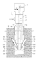
定着部材3は、例えば、回動して地盤に定着するために必要な所定の長さを有する棒状の部材であって、引張りロッド2の周方向に等配されて4本設けられている。尚、図3以外の図面では、説明の便宜のため、2本の定着部材3のみを図示し、他の2本については省略している。定着部材3は、その一端側が引張りロッド2の先端側の金属片22に金属製薄板23を介して回動可能に取り付けられている。これにより、それぞれの定着部材3は、金属製薄板23が高さ方向の略中央部分で折り曲がることによって、図1に示すように、定着部材3の他端側がそれぞれ引張りロッド2に対して近接している閉鎖状態から図2に示すように、他端側が引張りロッド2に対して離隔する方向へ拡翼するように構成されている。尚、拡翼とは、定着部材3の他端側が引張りロッド2から離隔するように定着部材3が一端側を基点として回動することを意味するものである。
The fixing
また、定着部材3の他端側の先端部には、図1に示すように、閉鎖状態において引張りロッド2と対向する腹部31側よりも反対側の背部32側の方が長尺になるように傾斜面33が形成されている。つまり、図1において、傾斜面33は、腹部31から背部32へ向かって上向きに傾斜するように形成されている。この傾斜面33の傾斜角度θとしては、例えば、30〜60度の範囲くらいに設定されており、定着部材が前記閉鎖状態の際に、後述する楔管5の先端のガイド面52と対向し、重なり合って当接するように構成されている。尚、傾斜面33は、必ずしも全体が平面である必要はなく、若干の曲面を有するように形成されていても良い。
Further, as shown in FIG. 1, the tip of the fixing
また、定着部材3は、地盤中で拡翼する際の抵抗を小さくするために、図3に示すように、背部32側の横断面形状が長さ方向の全体にわたって、又は長さ方向の一部において山形形状又は三角形状に形成されている。これにより、定着部材3は、地盤中の土等に食い込みながら拡翼する際の抵抗を小さくすることができるので、地盤中での拡翼が容易になる。尚、本実施形態では、アースアンカー1は、4本の定着部材3を備えている場合を例にしているが、定着部材3の個数は4本に限定されるものではなく、少なくとも2本以上設けられていれば良い。また、本実施形態のアースアンカー1では、定着部材3を回動可能に構成するために、折り曲げ可能な金属製薄板23を用いる場合を例にしているが、定着部材3を回動させるための構成はこれに限定されるものではなく、例えば、ヒンジ等を用いて、定着部材3の一端側を軸回転させるように構成しても良い。
Further, in order to reduce the resistance when the blades are expanded in the ground, as shown in FIG. 3, the fixing
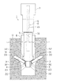
ストッパ部4は、定着部材3が所定の回動角度α以上は拡翼しないように規制するためのものであって、図1及び図2に示すように、引張りロッド2の先端側の金属片22に溶着されている金属製薄板23の外面側における高さ方向の前半部にそれぞれ固着されている。従って、金属製薄板23がその略中央部分で折れ曲がることによりその折曲位置を中心として回動した定着部材3は、図2に示すように、その後端面がストッパ部4に当接することによって停止し、引張りロッド2に対して所定の回動角度αを超えて拡翼しないように構成されている。尚、定着部材3の回動が規制される所定の回動角度αは、特に限定されるものではないが、強固にアースアンカー1を地盤に定着できるように、60〜90度の範囲で停止するようにストッパ部4が設けられていることが好ましい。
The
楔管5は、図1及び図2に示すように、引張りロッド2の径よりも大径の貫通孔51を有するように中空状に形成されており、引張りロッド2を貫通孔51内に挿通させた状態で、引張りロッド2の軸方向に沿って移動可能なように構成されている。また、この楔管5は、先端に定着部材3が閉鎖状態の際に定着部材3の傾斜面33と重なり合うように当接するガイド面52を有している。このガイド面52は、内側から外側へ向けて後端側へ傾斜面33の傾斜角度θと略同様の角度だけ傾斜するように形成されている。これにより、楔管5を複数の定着部材3に対して押し込んだ際に、ガイド面52から傾斜面33に対して水平方向への力が加わることによって、それぞれの定着部材3は効率良くスムーズに拡翼し始めることができるようになっている。
As shown in FIGS. 1 and 2, the
ねじ管6は、詳しくは図示しないが、内周面に引張りロッド2の外周面に形成されている雄ねじ21と螺合可能な雌ねじが形成されているナット状の部材である。従って、ねじ管6は、図1及び図2に示すように、引張りロッド2の雄ねじ21に螺合された状態で、引張りロッド2に対してねじ込まれることにより、引張りロッド2の軸方向の先端側へ移動することができるようになっている。
Although not shown in detail, the
また、ねじ管6には、詳しくは図示しないが、例えば、ねじ管6の回転を測定するための回転検出器を設けておくようにしても良い。これにより、アースアンカー1では、例えば、ねじ管6の位置が楔管5を複数の定着部材3に対して押し込む直前の初期位置にくる状態からのねじ管6の回転を測定することにより、ねじ管6が初期位置から引張りロッド2の軸方向の先端側へ移動した距離(変位)がわかるので、予めねじ管6の初期位置からの回転数又は軸方向への変位と、定着部材3の拡翼角度との関係を求めておくことで、回転検出器から得られる測定値に基づいて、定着部材3がどのくらい拡翼したかを把握することができる。従って、作業者は、アースアンカー1を地盤に定着させる際に定着部材3の拡翼状態を確認しながら、作業を行うことできるので、定着部材3がストッパ部4によって規制される所定角度αまで拡翼したことも把握することができ、必要以上にねじ管6を引張りロッド2に対してねじ込むことを回避し、定着部材3等の破損等を防止することができる。
Although not shown in detail in the
ボーリングマシン7は、引張りロッド2を後端側へ瞬間的に移動させるための逆打撃を加える逆打撃手段としての機能(バックハンマー機能)を有するものである。ここでは、ボーリングマシン7として、逆打撃機能と共に、引張りロッド2の地表側への引き上げ動作及びねじ管6の引張りロッド2に対するねじ込み動作も同時に1台で行うことができるように、引張りロッド2の引き上げ動作を行うための力を加えるフィード機能、及び、ねじ管6のねじ込み動作を行うための力を加える回転機能を備えているものを用いている。このようなボーリングマシン7としては、例えば、ESD40II(株式会社エムズ製)等の従来公知のボーリングマシンを用いることができる。尚、ボーリングマシン7自体は、従来公知のものであり、ここではその詳細な機構等についての説明は省略する。
The
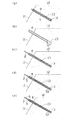
以下、このようなアースアンカー1を用いた本発明に係るアースアンカーの定着方法の一例について、図面を参照しつつ説明する。まず、図4(a)に示すように、法面や石積み擁壁等の斜面11の地盤12に細長い掘削孔13を形成する。この掘削工程では、例えば、ボーリングマシン等を用いて削孔を行うことによって掘削孔13を形成する。図4(a)では、ボーリングマシンを用いて、二重管掘削によって掘削孔13を形成する場合の様子を示している。二重管掘削では、図4(a)に示すように、一番外側に中空状の外管(ケーシングパイプ)8を使用し、その内側に先端にビット10が取り付けられている内管9が設けられている。そして、ビット10を回転させながら、掘り進めていくことによって掘削孔13が形成される。この掘削孔13は、例えば、長さが数m〜十数m程度、径dが数十mm〜百数十mm程度に形成される。このような掘削孔13は、斜面11の地盤12に複数個形成され、例えば、高さ方向に1.5m〜2.0mの間隔、水平方向に3m〜4mの間隔で千鳥状に配置して複数個の掘削孔13を形成する。
Hereinafter, an example of the fixing method of the earth anchor according to the present invention using such an
その後、図4(b)に示すように、内管9及びビット10を掘削孔13から引き抜く。一方、外管8は、定着部材3の拡翼のためのスペースを確保しつつ、掘削孔13の壁面が壊れることを防止するために、所定距離h(例えば、1m程度)だけ引き上げた状態で残しておく。尚、外管8が引き上げられる所定距離hは、特に限定されるものではなく、掘削孔13の長さや定着部材3の大きさ等に応じて適宜設定すれば良く、少なくとも定着部材3の拡翼動作を阻害しないようにスペースが確保されていれば良い。
Thereafter, as shown in FIG. 4B, the inner tube 9 and the
次に、図4(c)に示すように、挿入工程では、アースアンカー1を掘削孔13内に定着部材3を閉鎖状態で、引張りロッド2の先端側から挿入し、アースアンカー1の先端が掘削孔13の底部に接触する状態で設置する。そして、図4(d)及び図6に示すように、差込工程では、楔管5の貫通孔51内に引張りロッド2を挿通させた状態で、楔管5の先端のガイド面52が定着部材3の傾斜面33と重なり合って当接するように楔管5を差し込む。
Next, as shown in FIG. 4C, in the insertion step, the
次に、図4(e)及び図6に示すように、初期位置設定工程では、ねじ管6の位置が楔管5を複数の定着部材3に対して押し込む直前の初期位置にくるように、ねじ管6の内周面に形成されている雌ねじ(不図示)を引張りロッド2の雄ねじ21に螺合させた状態で、ねじ込んでいき、ねじ管6の先端と楔管5の後端が当接する状態に設定する。
Next, as shown in FIGS. 4E and 6, in the initial position setting step, the position of the
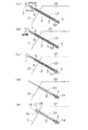
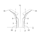
その後、図5(a)及び図6に示すように、引張りロッド2の地表側への引き上げ動作を行うためのフィード機能、ねじ管6のねじ込み動作を行うための回転機能、及び、引張りロッド2を後端側(地表側)へ瞬間的に移動させるための逆打撃機能を有するボーリングマシン7をセットする。そして、定着工程では、このボーリングマシン7を用いて、引張りロッド2を地表側に引張ると共に、ねじ管6を引張りロッド2に対してねじ込むことにより引張りロッド2の軸方向の先端側へ移動させ、楔管5の後端側から楔管5を複数の定着部材3に対して押し込むことで、複数の定着部材3を拡翼させる。この際、例えば、図9に示すように、定着部材3の拡翼に伴う地盤中の土等からの抵抗を軽減させるために、定着部材3の背部32側の上端に位置する点Pが所望の軌跡lに沿って拡翼するように、引張りロッド2を地表側への引き上げ及びねじ管6の引張りロッド2に対するねじ込みを調整することが好ましい。この軌跡lは、図9に示すような軌跡に必ずしも一義的に決定されるものではなく、地盤の状況や定着部材の形状等に応じて、好ましい軌跡は変わってくるものであり、予め地盤の硬さ等の調査を行った上で、適宜設定すれば良い。尚、図9中の二点鎖線は、定着部材3の背部32側の下端に位置する点Pと上端に位置する点Qとを結ぶ線分の軌跡を示しており、点Pの位置がY軸方向へ移動するに従って、点QはX軸方向へ移動することによって、定着部材3が拡翼していく様子を示している。
After that, as shown in FIGS. 5A and 6, the feed function for performing the pulling-up operation of the
また、定着工程では、図5(b)及び図7に示すように、定着部材3が一定の角度まで拡翼すると、地盤等の状況によっては、地盤中の土等からの抵抗が大きくなり、引張りロッド2を地表側に引張ると共に、ねじ管6を引張りロッド2に対してねじ込むだけの力では、定着部材3を拡翼させることが難しくなる場合がある。この際、例えば、ボーリングマシン7の逆打撃機能を用いて、引張りロッド2を後端側(地表側)へ瞬間的に移動させるための逆打撃を小刻みに連続的に加える。これにより、瞬間的に定着部材3が若干開くので、その瞬間にねじ管6を引張りロッド2に対してねじ込んでいき、楔管5をそれぞれの定着部材3に対して押し込むことで、図5(c)及び図8に示すように、それぞれの定着部材3をストッパ部4によって規制される所定角度αまで容易に拡翼させ、アースアンカー1を地盤12中に定着させることができる。尚、ボーリングマシン7による逆打撃については、最初は小さな力で開始し、定着部材3がなかなか拡翼し難い場合には、徐々に逆打撃の力を強めていくことが好ましい。
Further, in the fixing process, as shown in FIGS. 5B and 7, when the fixing
その後、図5(d)に示すように、ボーリングマシン7、ねじ管6、楔管5等を取り外し、不図示のモルタル注入用ホース等を用いて、掘削孔13内の引張りロッド2の先端側及び定着部材3が位置している部分にモルタル14を充填する。尚、このモルタル14は、主に引張りロッド2の先端側及び定着部材3等の錆止めを目的としているので、図5(d)では、掘削孔13内の引張りロッド2の先端側のみにモルタル14を充填している例を示しているが、掘削孔13内に挿入されている引張りロッド2の全長にわたってモルタル14を充填するようにしても良い。また、図10に示すように、引張りロッド2の先端に予めカプセル部材19を取り付けておき、そこにモルタル14を充填するようにしても良い。
Thereafter, as shown in FIG. 5 (d), the
このカプセル部材19は、例えば、透明な樹脂製の部材であって、図10に示すように後端側にアースアンカー1の先端側が挿入可能な開口部191を有するように略円筒状に形成されている。また、カプセル部材19は、掘削孔13内にアースアンカー1の先端側と共に挿入できるように、カプセル部材19の外径は掘削孔13の径よりも小径に形成されている。尚、図10では、説明の便宜のため、楔管5等については省略して図示している。このカプセル部材19は、図10に示すように、定着部材3が拡翼する際に定着部材3と接触しないように外周面上に定着部材3が通過できるスリット状の窓部192が定着部材3の個数分だけ形成されている。また、カプセル部材19の底部には、図10(b)に示すように、カプセル部材19内にモルタル14が注入された際に、掘削孔13の底部にもモルタル14が流れ込むように供給孔193が形成されている。このようなカプセル部材19を予め引張りロッド2の先端に取り付けておくことで、アースアンカー1では、先端側から掘削孔13内へ挿入する際に定着部材3等が掘削孔13の壁面に接触して壁面が破壊されたりすることを防止することができ、挿入工程を効率良く行うことができる。
The
その後、図5(e)に示すように、斜面11における地盤12表面に露出したアースアンカー1の頭部の処理を行う。ここでは、例えば、斜面11に支圧板15を設置し、その上に台座16を設けている。そして、引張りロッド2の雄ねじ21と螺合可能な雌ねじを有するナット部材17を用いて締結することにより、固定した後、キャップ部材18をアースアンカー1の頭部に被せる。その後、複数個のアースアンカー1を相互にワイヤロープ(不図示)等で連結させ、格子状にワイヤーロープを編成して斜面11の地盤12の緩みを防止し安定化させる。
Then, as shown in FIG.5 (e), the process of the head of the
尚、本発明の実施の形態は上述の形態に限るものではなく、本発明の思想の範囲を逸脱しない範囲で適宜変更することができる。 The embodiment of the present invention is not limited to the above-described embodiment, and can be appropriately changed without departing from the scope of the idea of the present invention.
1 アースアンカー
2 引張りロッド
21 雄ねじ
3 定着部材
31 腹部
32 背部
33 傾斜面
4 ストッパ部
5 楔管
51 貫通孔
52 ガイド面
6 ねじ管
7 ボーリングマシン(逆打撃手段)
12 地盤
13 掘削孔
DESCRIPTION OF
12
Claims (4)
前記引張りロッドの先端側に一端側がそれぞれ回動可能に取り付けられ、他端側がそれぞれ前記引張りロッドに対して近接している閉鎖状態から前記引張りロッドに対して離隔する方向へ拡翼し、前記他端側の先端部は、前記閉鎖状態において前記引張りロッドと対向する腹部側よりも反対側の背部側の方が長尺になるように傾斜面が形成されている複数の定着部材と、
前記定着部材が所定角度以上は拡翼しないように規制するストッパ部と、
前記引張りロッドの径よりも大径の貫通孔を有するように中空状に形成され、前記引張りロッドを前記貫通孔内に挿通させた状態で前記引張りロッドの軸方向に移動可能な楔管と、
内周面に前記引張りロッドの前記雄ねじと螺合可能な雌ねじを有し、前記引張りロッドに対してねじ込まれることにより前記引張りロッドの軸方向の先端側へ移動して、前記楔管の後端側から前記楔管を前記複数の定着部材に対して押し込むことで、前記複数の定着部材を拡翼させるねじ管と、を備えることを特徴とするアースアンカー。 A tension rod having a predetermined length and having an external thread formed on the outer peripheral surface;
One end side is rotatably attached to the tip end side of the tension rod, and the other end side is expanded in a direction away from the tension rod from a closed state where the other end side is close to the tension rod. A plurality of fixing members having an inclined surface formed so that the distal end portion on the end side is longer on the back side opposite to the abdomen side facing the tension rod in the closed state;
A stopper portion for restricting the fixing member so as not to expand the blade beyond a predetermined angle;
A wedge tube that is formed in a hollow shape so as to have a through-hole having a diameter larger than the diameter of the tension rod, and is movable in the axial direction of the tension rod in a state where the tension rod is inserted into the through-hole.
An inner peripheral surface has a female screw that can be screwed with the male screw of the tension rod, and moves to the tip end side in the axial direction of the tension rod by being screwed into the tension rod, so that the rear end of the wedge tube An earth anchor comprising: a screw tube that expands the plurality of fixing members by pushing the wedge tube from the side into the plurality of fixing members.
地盤に掘削孔を形成する掘削工程と、
前記アースアンカーを前記掘削孔内に前記定着部材を前記閉鎖状態で、前記引張りロッドの先端側から挿入する挿入工程と、
前記楔管の先端が前記定着部材の前記傾斜面と当接するように前記楔管を前記引張りロッドに差し込む差込工程と、
前記ねじ管の位置が前記楔管を前記複数の定着部材に対して押し込む直前の初期位置にくるように、前記引張りロッドの前記雄ねじに前記雌ねじを螺合させる初期位置設定工程と、
前記引張りロッドを地表側に引張ると共に、前記ねじ管を前記引張りロッドに対してねじ込むことにより前記引張りロッドの軸方向の先端側へ移動させ、前記楔管の後端側から前記楔管を前記複数の定着部材に対して押し込むことで、前記複数の定着部材を拡翼させて、前記アースアンカーを前記地盤に定着させる定着工程と、を含むことを特徴とするアースアンカーの定着方法。 A method for fixing an earth anchor using the earth anchor according to claim 1,
An excavation process for forming an excavation hole in the ground;
An insertion step of inserting the ground anchor into the excavation hole from the distal end side of the pulling rod in the closed state;
An insertion step of inserting the wedge tube into the pulling rod so that the tip of the wedge tube is in contact with the inclined surface of the fixing member;
An initial position setting step of screwing the female screw into the male screw of the pull rod so that the position of the screw tube is at an initial position immediately before the wedge tube is pushed into the plurality of fixing members;
The pulling rod is pulled to the ground surface side, and the screw tube is screwed into the pulling rod to move to the tip end side in the axial direction of the pulling rod, and the plurality of wedge tubes are moved from the rear end side of the wedge tube. A fixing step of fixing the earth anchor to the ground by expanding the plurality of fixing members by being pushed into the fixing member.
Priority Applications (1)
| Application Number | Priority Date | Filing Date | Title |
|---|---|---|---|
| JP2016085146A JP2017193880A (en) | 2016-04-21 | 2016-04-21 | Earth anchor and fixation method of earth anchor |
Applications Claiming Priority (1)
| Application Number | Priority Date | Filing Date | Title |
|---|---|---|---|
| JP2016085146A JP2017193880A (en) | 2016-04-21 | 2016-04-21 | Earth anchor and fixation method of earth anchor |
Publications (1)
| Publication Number | Publication Date |
|---|---|
| JP2017193880A true JP2017193880A (en) | 2017-10-26 |
Family
ID=60155444
Family Applications (1)
| Application Number | Title | Priority Date | Filing Date |
|---|---|---|---|
| JP2016085146A Pending JP2017193880A (en) | 2016-04-21 | 2016-04-21 | Earth anchor and fixation method of earth anchor |
Country Status (1)
| Country | Link |
|---|---|
| JP (1) | JP2017193880A (en) |
Cited By (8)
| Publication number | Priority date | Publication date | Assignee | Title |
|---|---|---|---|---|
| CN109024627A (en) * | 2018-08-15 | 2018-12-18 | 中国人民解放军军事科学院国防工程研究院 | A kind of novel lattice-anchor pole-anchor cable composite slope ruggedized construction and construction method |
| CN110397033A (en) * | 2019-07-26 | 2019-11-01 | 安徽理工大学 | It is a kind of at bolt tool and with the how horizontal bolt soil anchor prepared at bolt tool |
| CN113235587A (en) * | 2021-04-27 | 2021-08-10 | 六盘水师范学院 | Anchoring agent injection device for prestress anchoring |
| JP7008376B1 (en) | 2021-04-22 | 2022-01-25 | アビエンジニアリング株式会社 | Anchor device |
| CN114086551A (en) * | 2021-11-02 | 2022-02-25 | 浙江科技学院 | Stock based on strike and consolidate anti buoyancy in increase soft soil |
| JP2022043473A (en) * | 2020-09-04 | 2022-03-16 | 株式会社大林組 | In-hole imaging device |
| JP2023525405A (en) * | 2020-07-06 | 2023-06-15 | 青▲島▼理工大学 | Expandable Inner Anchor Head for Prestressed Anchor Cables |
| WO2025222635A1 (en) * | 2024-04-23 | 2025-10-30 | 中国安全生产科学研究院 | Grouting pipe and construction method for desert water storage area |
-
2016
- 2016-04-21 JP JP2016085146A patent/JP2017193880A/en active Pending
Cited By (13)
| Publication number | Priority date | Publication date | Assignee | Title |
|---|---|---|---|---|
| CN109024627A (en) * | 2018-08-15 | 2018-12-18 | 中国人民解放军军事科学院国防工程研究院 | A kind of novel lattice-anchor pole-anchor cable composite slope ruggedized construction and construction method |
| CN110397033A (en) * | 2019-07-26 | 2019-11-01 | 安徽理工大学 | It is a kind of at bolt tool and with the how horizontal bolt soil anchor prepared at bolt tool |
| CN110397033B (en) * | 2019-07-26 | 2024-01-26 | 安徽理工大学 | A bolting tool and a multi-lateral bolt soil anchor prepared using the bolting tool |
| JP2023525405A (en) * | 2020-07-06 | 2023-06-15 | 青▲島▼理工大学 | Expandable Inner Anchor Head for Prestressed Anchor Cables |
| JP7318878B2 (en) | 2020-07-06 | 2023-08-01 | 青▲島▼理工大学 | Expandable Inner Anchor Head for Prestressed Anchor Cables |
| JP7629699B2 (en) | 2020-09-04 | 2025-02-14 | 株式会社大林組 | Borehole photography device |
| JP2022043473A (en) * | 2020-09-04 | 2022-03-16 | 株式会社大林組 | In-hole imaging device |
| JP2022167041A (en) * | 2021-04-22 | 2022-11-04 | アビエンジニアリング株式会社 | Anchor device |
| JP7008376B1 (en) | 2021-04-22 | 2022-01-25 | アビエンジニアリング株式会社 | Anchor device |
| CN113235587A (en) * | 2021-04-27 | 2021-08-10 | 六盘水师范学院 | Anchoring agent injection device for prestress anchoring |
| CN114086551A (en) * | 2021-11-02 | 2022-02-25 | 浙江科技学院 | Stock based on strike and consolidate anti buoyancy in increase soft soil |
| CN114086551B (en) * | 2021-11-02 | 2023-09-29 | 浙江科技学院 | An anchor based on impact reinforcement to increase anti-buoyancy in soft soil |
| WO2025222635A1 (en) * | 2024-04-23 | 2025-10-30 | 中国安全生产科学研究院 | Grouting pipe and construction method for desert water storage area |
Similar Documents
| Publication | Publication Date | Title |
|---|---|---|
| ES2798073T3 (en) | Friction bolt | |
| KR100808849B1 (en) | Anchor device with an elastic expansion sleeve | |
| KR101329054B1 (en) | Anchor for ground | |
| KR101481123B1 (en) | Extension excavation machine of soft ground and method for reinforcing soft ground using the same | |
| KR101376534B1 (en) | Anchor for rock bolt | |
| KR100598024B1 (en) | Wedge anchor | |
| JP2015014180A (en) | Underground anchor, and antiseismic reinforcement method of artificial slope using the same | |
| EA011700B1 (en) | An anchoring device | |
| JP2999190B1 (en) | Expansion type anchor member | |
| KR101546142B1 (en) | Earth anchor and installation method thereof | |
| KR20070069101A (en) | Fixed nailing device and construction method | |
| RU187334U1 (en) | ANCHOR TUBE FRICTION FASTENER | |
| JP2999189B1 (en) | Expansion type anchor member | |
| JP6779566B2 (en) | Post-construction anchor and its installation structure | |
| KR101681898B1 (en) | Rotary pile and construction method using the same | |
| ES2369485T3 (en) | PROCEDURE AND DEVICE FOR DRILLING, IN PARTICULAR DRILLING BY PERCUSSION OR BY ROTOPERCUSION OF A HOLE ON GROUND OR ROCKY MATERIAL. | |
| JP2017155414A (en) | Fixation method of earth anchor | |
| KR102426610B1 (en) | Structure body of ground anchor with extending blades and system of ground anchor with extending blades and method constructing ground anchor thereof | |
| KR102299598B1 (en) | Multi-suprrort underground anchor for rock | |
| BR112017027667B1 (en) | Radially expandable tie rod | |
| JP6530944B2 (en) | Anchor mounting structure and mounting method | |
| KR101570525B1 (en) | Screw anchor pile | |
| JP6411130B2 (en) | Driven pile | |
| KR101508992B1 (en) | Extension type casing and soft ground reinforcement method using the same | |
| JP6505811B1 (en) | Resistance pile |