JP2017193975A - Air intake duct - Google Patents
Air intake duct Download PDFInfo
- Publication number
- JP2017193975A JP2017193975A JP2016083594A JP2016083594A JP2017193975A JP 2017193975 A JP2017193975 A JP 2017193975A JP 2016083594 A JP2016083594 A JP 2016083594A JP 2016083594 A JP2016083594 A JP 2016083594A JP 2017193975 A JP2017193975 A JP 2017193975A
- Authority
- JP
- Japan
- Prior art keywords
- air intake
- duct
- air
- head portion
- head
- Prior art date
- Legal status (The legal status is an assumption and is not a legal conclusion. Google has not performed a legal analysis and makes no representation as to the accuracy of the status listed.)
- Granted
Links
Images

Landscapes
- Cooling, Air Intake And Gas Exhaust, And Fuel Tank Arrangements In Propulsion Units (AREA)
- Body Structure For Vehicles (AREA)
Abstract
【課題】吸気ダクトのヘッド部上面に降り注いだ雨水が空気取入口から吸い込まれてしまう現象を確実に防止し得る吸気ダクトを提供する。【解決手段】車両のキャブの上面に乗り上げたヘッド部4aの車幅方向外側に開口した空気取入口2から外気をエンジン用吸気として取り入れる吸気ダクト7に関し、前記ヘッド部4aの後部下面から前記キャブの後面に沿い下方へ延びるダクト部4bの直上を避けて前記空気取入口2を開口し、該空気取入口2の後方端と隣接する位置に前記ヘッド部4aの底面11に溜まる水を堰き止める竪壁10を備えた。【選択図】図1PROBLEM TO BE SOLVED: To provide an intake duct capable of reliably preventing a phenomenon that rainwater that has poured down on the upper surface of a head portion of the intake duct is sucked from an air intake. An intake duct (7) for taking in outside air as engine intake air from an air intake port (2) opened to the outside in the vehicle width direction of a head portion (4a) that rides on the upper surface of a cab of a vehicle, the cab from the rear lower surface of the head portion (4a). The air intake port 2 is opened so as not to be located immediately above the duct part 4b extending downward along the rear surface of the air intake part, and the water accumulated on the bottom surface 11 of the head part 4a is blocked at a position adjacent to the rear end of the air intake port 2. The vertical wall 10 was provided. [Selection diagram] Figure 1
Description
本発明は、吸気ダクトに関するものである。 The present invention relates to an intake duct.
一般的に、トラック等の大型の運搬車両は、普通乗用車と比べて未舗装の悪路を走行する機会が多いため、エンジンの吸気としては、塵埃が多く含まれている地面付近の外気ではなく、地面から十分高い部分の清浄な外気を取り入れることが好ましく、また、地面付近では雨水や積雪の跳ね上げを一緒に取り込んでしまう虞れもあるため、地面から十分高い部分で外気だけを確実に取り入れることが好ましい。 In general, large transport vehicles such as trucks have more opportunities to travel on unpaved rough roads than ordinary passenger cars, so the engine intake air is not the outside air near the ground that contains a lot of dust. Therefore, it is preferable to take in clean outside air at a sufficiently high part from the ground, and there is a risk of rainwater and snow splashing up near the ground, so make sure that only outside air is at a sufficiently high part from the ground. It is preferable to incorporate.
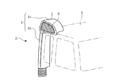
そこで、大型の運搬車両においては、キャブの後面に上下方向に長く延在する吸気ダクトを据え付けるようにしているが、図2に示す如く、近年においては、より清浄な外気を取り込み得るようキャブ1の上面で空気取入口2を開口した吸気ダクト3が提案されている。
Therefore, in a large transport vehicle, an intake duct that extends in the vertical direction is installed on the rear surface of the cab. However, as shown in FIG. 2, in recent years, the cab 1 can take in cleaner outside air. An air intake duct 3 having an
斯かる吸気ダクト3によれば、エンジンルームからの熱気の影響の少ない十分に冷えた外気を取り込めることでエンジンの各気筒への吸気の充填効率を高め、しかも、より高い位置で清浄な外気を取り込めることでエアクリーナの長寿命化を図り、圧力損失の少ない運転状態を長期に亘り維持させて燃費の向上を図るといったメリットが得られる。 According to such an intake duct 3, the intake efficiency of the intake air into each cylinder of the engine is increased by taking in the sufficiently cooled outside air that is less affected by the hot air from the engine room, and moreover clean air is supplied at a higher position. By taking it in, it is possible to prolong the life of the air cleaner and to maintain the operation state with little pressure loss for a long period of time and to improve the fuel efficiency.
ここで、前記吸気ダクト3の外殻構造を成しているダクト本体4は、キャブ1の後面側から上面に乗り上げて前記空気取入口2を車幅方向外側(図2中における左側)へ開口したヘッド部4aと、該ヘッド部4aの後部下面から下方に延びて前記キャブ1の後面に沿うダクト部4bとで構成されているが、空気取入口2から車幅方向内側へ向けて取り込まれた外気がヘッド部4a内で車両後方へ回り込むように流れることになるため、図3に分解図を示す如く、外気の流れの回り込みを円滑に誘導するための仕切板5が前記ヘッド部4aに内蔵されるようになっている。
Here, the
従来、この種の仕切板5は、別部品の分割ピース5a,5bを前記ヘッド部4aのブロー成形後に空気取入口2から挿入して組み付けるようにしており、その組み付け後に前記空気取入口2をルーバー6で被覆して雨水の直接的な降り込みを阻む(雪の侵入も同様にして阻まれる)ようにしている。
Conventionally, the
このようにした場合、空気取入口2から車幅方向内側へ向けて取り込まれた外気の流れが仕切板5により車両後方へ円滑に回り込むように誘導されるだけでなく、その回り込みの間に雨や雪が仕切板5の壁面に衝突したり底面に落下したりすることで外気の流れから逸脱してダクト部4bへの侵入を阻まれることになる。
In this case, the flow of outside air taken in from the
ここで、仕切板5の分割ピース5aには、その底面に溜まる水を空気取入口2側へ流し戻す傾斜が付されており、該空気取入口2の下端付近に設けた図示しない排水口からヘッド部4aの外へ排出し得るようにしてある。
Here, the
尚、本発明に関連する一般的な既存技術について説明されている先行技術文献情報としては、本発明と同じ出願人による下記の特許文献1、2等が既に存在している。
In addition, as prior art document information explaining general existing technology related to the present invention, the following
しかしながら、前述した如き従来構造にあっては、ヘッド部4aの底面と仕切板5の分割ピース5aとの間に僅かな隙間ができてしまうことが避けられないため、この隙間に入り込んだ雨や雪の解け水が毛細管現象によりダクト部4bまで導かれて流れ落ちてしまうという問題があり、仮に仕切板5が装備されていなかったとしても、ヘッド部4a内に入り込んでしまった雨や雪の解け水がダクト部4bへ向かうことを傾斜だけで防ぎきることは困難であった。
However, in the conventional structure as described above, it is inevitable that a slight gap is formed between the bottom surface of the
本発明は上述の実情に鑑みてなしたもので、雨や雪の解け水がダクト部まで導かれて流れ落ちてしまうことを確実に防止し得る吸気ダクトを提供することを目的とする。 The present invention has been made in view of the above-described circumstances, and an object thereof is to provide an intake duct that can reliably prevent rain and snow melting water from being led to the duct portion and flowing down.
本発明は、車両のキャブの上面に乗り上げたヘッド部の車幅方向外側に開口した空気取入口から外気をエンジン用吸気として取り入れる吸気ダクトであって、前記ヘッド部の後部下面から前記キャブの後面に沿い下方へ延びるダクト部の直上を避けて前記空気取入口を開口し、該空気取入口の後方端と隣接する位置に前記ヘッド部の底面に溜まる水を堰き止める竪壁を備えたことを特徴とするものである。 The present invention is an intake duct that takes in outside air as intake air for an engine from an air intake opening that is open to the vehicle width direction outside of a head portion that rides on an upper surface of a cab of a vehicle, and includes a rear surface of the cab from a rear lower surface of the head portion. The air intake opening is opened so as to avoid the upper portion of the duct portion extending downward along the line, and a wall is provided at a position adjacent to the rear end of the air intake to block water accumulated on the bottom surface of the head portion. It is a feature.
而して、このようにすれば、空気取入口がダクト部の直上を避けて開口されているので、外気がヘッド部の前方側から回り込んでダクト部に向かう流れとなり、その回り込みの間に雨や雪が壁面に衝突したり底面に落下したりすることで外気の流れから逸脱してダクト部への侵入を阻まれると共に、空気取入口からダクト部への直接的な雨や雪の侵入も阻止され、しかも、ヘッド部内に残った雨や雪の解け水が竪壁によりダクト部側へ入り込まないように確実に堰き止められる。尚、竪壁により堰き止められてヘッド部内に残った雨や雪の解け水は、該ヘッド部の底面に傾斜を付したり排水口を設けたりすることで前記ヘッド部の外へ排出できるようにしておけば良い。 Thus, in this way, since the air intake port is opened so as not to be directly above the duct portion, the outside air flows from the front side of the head portion and flows toward the duct portion. Rain and snow collide with the wall surface and fall to the bottom surface to deviate from the flow of outside air and prevent entry into the duct part, and direct rain and snow entry from the air intake to the duct part In addition, the rain and snow remaining in the head portion are reliably dammed so as not to enter the duct portion side by the dredging wall. It should be noted that the rain and snow melting water remaining in the head portion after being dammed by the dredging wall can be discharged out of the head portion by inclining the bottom surface of the head portion or providing a drain outlet. It ’s good if you keep it.
更に、本発明においては、ヘッド部を空気取入口の後方端を境界として前後に分割構成し、その分割したヘッド部の後方部分における開放端面の下側に竪壁を形成することが好ましく、このようにすれば、ヘッド部の後方部分を含むダクト部のブロー成形時に竪壁を簡単に一体成形することが可能であり、竪壁を別部品として後加工で取り付ける場合であっても、ヘッド部の前方部分を組み付ける前の段階であれば簡単に竪壁の取り付けを行うことが可能である。 Furthermore, in the present invention, it is preferable to divide the head part into front and rear parts with the rear end of the air intake as a boundary, and to form a wall on the lower side of the open end surface in the rear part of the divided head part. By doing so, it is possible to easily integrally mold the ridge wall during blow molding of the duct portion including the rear portion of the head portion, and even if the ridge wall is attached as a separate part by post-processing, the head portion If it is a stage before assembling the front part, the wall can be easily attached.
尚、ヘッド部を前後に分割した構造とすれば、外気を円滑に回り込ませるための仕切板をインサート品として溶融樹脂で包み込んで固化させることで前記仕切板を一体化したヘッド部の前方部分を簡単に成形することが可能となり、別部品の仕切板を後加工で組み付ける場合よりも流路断面積を効率良く大きく確保することも可能となる。 In addition, if the head part is divided into front and rear parts, the front part of the head part integrated with the partition plate by wrapping and solidifying the partition plate for smoothly circulating outside air as an insert product with molten resin. It becomes possible to form easily, and it is also possible to efficiently secure a large cross-sectional area of the flow path as compared with the case where a separate partition plate is assembled by post-processing.
上記した本発明の吸気ダクトによれば、下記の如き種々の優れた効果を奏し得る。 According to the intake duct of the present invention described above, various excellent effects as described below can be obtained.
(I)本発明の請求項1に記載の発明によれば、外気をヘッド部の前方側から回り込ませてダクト部に向かう流れとし、その回り込みの間に雨や雪を外気の流れから逸脱させてダクト部への侵入を阻止することができると共に、空気取入口からダクト部への直接的な雨や雪の侵入も阻止することができ、しかも、ヘッド部内に残った雨や雪の解け水を竪壁によりダクト部側へ入り込まないように確実に堰き止めることができるので、雨や雪の解け水がダクト部まで導かれて流れ落ちてしまうことを確実に防止することができる。 (I) According to the invention described in claim 1 of the present invention, outside air is circulated from the front side of the head portion to flow toward the duct portion, and rain and snow are allowed to deviate from the outside air flow during the wraparound. In addition to preventing the intrusion into the duct part, it is also possible to prevent the intrusion of rain and snow directly from the air intake into the duct part, and the rain and snow melting water remaining in the head part. Can be reliably dammed so as not to enter the duct portion side by the dredging wall, so that it is possible to surely prevent rain and snow melting water from being led to the duct portion and flowing down.
(II)本発明の請求項2に記載の発明によれば、ヘッド部の後方部分を含むダクト部のブロー成形時に竪壁を簡単に一体成形することができ、また、竪壁を別部品として後加工で取り付ける場合でもヘッド部の前方部分を組み付ける前に簡単に竪壁の取り付けを行うことができる。
(II) According to the invention described in
以下、本発明の実施の形態を図面を参照しつつ説明する。 Hereinafter, embodiments of the present invention will be described with reference to the drawings.
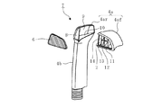
図1は本発明を実施する形態の一例を示すもので、図2及び図3と同一の符号を付した部分は同一物を表わしている。 FIG. 1 shows an example of an embodiment for carrying out the present invention, and the portions denoted by the same reference numerals as those in FIGS. 2 and 3 represent the same items.
本形態例における吸気ダクト7は、先に図2及び図3で説明した従来の吸気ダクト3の場合と略同様に、運搬車両のキャブ1(図2参照)の後面に据え付けられて上下方向に延在し且つ該キャブ1の上面に乗り上げたヘッド部4aの車幅方向外側に開口した空気取入口2から外気をエンジン用吸気として取り入れるように構成されているが、前記ヘッド部4aの後部下面から前記キャブ1の後面に沿い下方へ延びるダクト部4bの直上を避けて前記空気取入口2を開口し、空気取入口2の後方端と隣接する位置に前記ヘッド部4aの底面11に溜まる水を堰き止める竪壁10を備えたところが特徴となっている。
In the present embodiment, the intake duct 7 is installed on the rear surface of the cab 1 (see FIG. 2) of the transport vehicle in the vertical direction, as in the case of the conventional intake duct 3 described with reference to FIGS. The
ここに図示している例の場合には、ヘッド部4aにおけるダクト部4bの直上に当たる後方部分4arと、その前方に延びてキャブ1の上面に乗り上げることになる前方部分4afとに前記ヘッド部4aが分割構成されており、前記後方部分4arの車幅方向外側に側面8を残す一方、前記前方部分4afの車幅方向外側を開放して空気取入口2を形成するようにしている。
In the case of the example shown here, the
即ち、本形態例におけるヘッド部4aは、空気取入口2の後方端を境界として前後に分割構成された構造となっており、その分割したヘッド部4aの後方部分4arにおける開放端面9の下側に車幅方向に亘る竪壁10が形成されていて、該竪壁10により前記ヘッド部4aの底面11に溜まる水を堰き止め得るようにしてある。
That is, the
ここで、後方部分4arの開放端面9の下側に竪壁10を形成するにあたっては、ヘッド部4aの後方部分4arを含むダクト部4bのブロー成形時に竪壁10を一体成形するようにすれば良いが、ヘッド部4aの前方部分4afを組み付ける前に竪壁10を別部品として後加工で取り付けることも可能である。
Here, when forming the
また、前記ヘッド部4aの底面11には、該底面11に溜まる水を空気取入口2側へ流し戻す傾斜が付されており、該空気取入口2下端に設けたドリップチャンネル12により前記水を回収して竪壁10側へ導き、排水口13からヘッド部4aの外へ排出できるようにしてある。
In addition, the
尚、水を排出するための排水口13を形成するにあたっては、ヘッド部4aの前方部分4afにおける後方部分4arとの嵌め合わせ部分の最下位置に凹み部を形成しておき、前方部分4afを後方部分4arに嵌め合わせた時に前記凹み部により前記竪壁10との間に隙間が形成されるようにし、該隙間を排水口13として利用するようにすれば良い。
In forming the
更に、本形態例においては、空気取入口2から車幅方向内側へ向けて取り込まれた外気がヘッド部4a内で車両後方へ回り込む流れとなるので、この回り込みを円滑に誘導し得るよう前記ヘッド部4aに仕切板14が内蔵されているが、この仕切板14を内蔵させるにあたっては、該仕切板14をインサート品として溶融樹脂で包み込んで固化させ、これにより前記仕切板14を一体化したヘッド部4aの前方部分4afとして成形することが可能である。
Further, in the present embodiment, since the outside air taken in from the
而して、このように吸気ダクト7を構成すれば、空気取入口2がダクト部4bの直上を避けて開口されているので、外気がヘッド部4aの前方側から回り込んでダクト部4bに向かう流れとなり、その回り込みの間に雨や雪が壁面に衝突したり底面に落下したりすることで外気の流れから逸脱してダクト部4bへの侵入を阻まれると共に、空気取入口2からダクト部4bへの直接的な雨や雪の侵入も阻止され、しかも、ヘッド部4a内に残った雨や雪の解け水が竪壁10によりダクト部4b側へ入り込まないように確実に堰き止められることになる。
Thus, if the intake duct 7 is configured in this way, the
尚、ダクト部4bへの侵入を阻まれてヘッド部4a内に残った雨や雪の解け水は、該ヘッド部4aの底面11に付された傾斜によりドリップチャンネル12に流下して回収され、該ドリップチャンネル12により竪壁10側へ導かれて排水口13からヘッド部4aの外へ排出される。
The rain and snow melting water remaining in the
従って、上記形態例によれば、外気をヘッド部4aの前方側から回り込ませてダクト部4bに向かう流れとし、その回り込みの間に雨や雪を外気の流れから逸脱させてダクト部4bへの侵入を阻止することができると共に、空気取入口2からダクト部4bへの直接的な雨や雪の侵入も阻止することができ、しかも、ヘッド部4a内に残った雨や雪の解け水を竪壁10によりダクト部4b側へ入り込まないように確実に堰き止めることができるので、雨や雪の解け水がダクト部4bまで導かれて流れ落ちてしまうことを確実に防止することができる。
Therefore, according to the above embodiment, the outside air is circulated from the front side of the
更に、特に本形態例においては、ヘッド部4aを空気取入口2の後方端を境界として前後に分割構成し、その分割したヘッド部4aの後方部分4arにおける開放端面の下側に竪壁10を形成するようにしているので、ヘッド部4aの後方部分4arを含むダクト部4bのブロー成形時に竪壁10を簡単に一体成形することができ、竪壁10を別部品として後加工で取り付ける場合であっても、ヘッド部4aの前方部分4afを組み付ける前の段階であれば簡単に竪壁10の取り付けを行うことができる。
Further, particularly in the present embodiment, the
また、ヘッド部4aが前後に分割構成されていれば、外気を円滑に回り込ませるための仕切板14をインサート品として溶融樹脂で包み込んで固化させることで前記仕切板14を一体化したヘッド部4aの前方部分4afを簡単に成形することができ、別部品の仕切板14を後加工で組み付ける場合よりも流路断面積を効率良く大きく確保することができる。
Moreover, if the
尚、本発明の吸気ダクトは、上述の形態例にのみ限定されるものではなく、本発明の要旨を逸脱しない範囲内において種々変更を加え得ることは勿論である。 Note that the intake duct of the present invention is not limited to the above-described embodiment, and it is needless to say that various modifications can be made without departing from the scope of the present invention.
1 キャブ
2 空気取入口
4a ヘッド部
4ar 後方部分
4b ダクト部
7 吸気ダクト
9 開放端面
10 竪壁
DESCRIPTION OF SYMBOLS 1
Claims (2)
Priority Applications (3)
| Application Number | Priority Date | Filing Date | Title |
|---|---|---|---|
| JP2016083594A JP6689528B2 (en) | 2016-04-19 | 2016-04-19 | Intake duct |
| CN201780024778.8A CN109072829A (en) | 2016-04-19 | 2017-02-15 | suction pipe |
| PCT/JP2017/005405 WO2017183268A1 (en) | 2016-04-19 | 2017-02-15 | Air intake duct |
Applications Claiming Priority (1)
| Application Number | Priority Date | Filing Date | Title |
|---|---|---|---|
| JP2016083594A JP6689528B2 (en) | 2016-04-19 | 2016-04-19 | Intake duct |
Publications (2)
| Publication Number | Publication Date |
|---|---|
| JP2017193975A true JP2017193975A (en) | 2017-10-26 |
| JP6689528B2 JP6689528B2 (en) | 2020-04-28 |
Family
ID=60155359
Family Applications (1)
| Application Number | Title | Priority Date | Filing Date |
|---|---|---|---|
| JP2016083594A Active JP6689528B2 (en) | 2016-04-19 | 2016-04-19 | Intake duct |
Country Status (1)
| Country | Link |
|---|---|
| JP (1) | JP6689528B2 (en) |
Cited By (2)
| Publication number | Priority date | Publication date | Assignee | Title |
|---|---|---|---|---|
| JP2017193974A (en) * | 2016-04-19 | 2017-10-26 | 日野自動車株式会社 | Intake duct |
| WO2024090002A1 (en) * | 2022-10-27 | 2024-05-02 | ダイムラー トラック エージー | Air intake duct structure for vehicle |
Citations (8)
| Publication number | Priority date | Publication date | Assignee | Title |
|---|---|---|---|---|
| GB2011273A (en) * | 1977-12-30 | 1979-07-11 | Fiat Veicoli Ind | Air-intake devices for internal combustion engines |
| JPS60139626U (en) * | 1984-02-29 | 1985-09-14 | いすゞ自動車株式会社 | Vehicle engine intake duct device |
| JPS6364527U (en) * | 1986-10-20 | 1988-04-28 | ||
| JPH045119U (en) * | 1990-04-27 | 1992-01-17 | ||
| US20090101014A1 (en) * | 2007-06-20 | 2009-04-23 | Michel Baseotto | Moisture separator arrangement; fluid intake for air cleaner; and,method |
| US20090151308A1 (en) * | 2007-12-14 | 2009-06-18 | Suk Hwan Jung | Intake duct system for an engine |
| WO2011094334A1 (en) * | 2010-01-29 | 2011-08-04 | Donaldson Company, Inc. | Water separator assembly for use with air cleaner; assembly; components; systems; and, methods |
| US20150267655A1 (en) * | 2012-12-06 | 2015-09-24 | Mann+Hummel Gmbh | Intake Module of an Air Intake Tract of an Internal Combustion Engine |
-
2016
- 2016-04-19 JP JP2016083594A patent/JP6689528B2/en active Active
Patent Citations (8)
| Publication number | Priority date | Publication date | Assignee | Title |
|---|---|---|---|---|
| GB2011273A (en) * | 1977-12-30 | 1979-07-11 | Fiat Veicoli Ind | Air-intake devices for internal combustion engines |
| JPS60139626U (en) * | 1984-02-29 | 1985-09-14 | いすゞ自動車株式会社 | Vehicle engine intake duct device |
| JPS6364527U (en) * | 1986-10-20 | 1988-04-28 | ||
| JPH045119U (en) * | 1990-04-27 | 1992-01-17 | ||
| US20090101014A1 (en) * | 2007-06-20 | 2009-04-23 | Michel Baseotto | Moisture separator arrangement; fluid intake for air cleaner; and,method |
| US20090151308A1 (en) * | 2007-12-14 | 2009-06-18 | Suk Hwan Jung | Intake duct system for an engine |
| WO2011094334A1 (en) * | 2010-01-29 | 2011-08-04 | Donaldson Company, Inc. | Water separator assembly for use with air cleaner; assembly; components; systems; and, methods |
| US20150267655A1 (en) * | 2012-12-06 | 2015-09-24 | Mann+Hummel Gmbh | Intake Module of an Air Intake Tract of an Internal Combustion Engine |
Cited By (2)
| Publication number | Priority date | Publication date | Assignee | Title |
|---|---|---|---|---|
| JP2017193974A (en) * | 2016-04-19 | 2017-10-26 | 日野自動車株式会社 | Intake duct |
| WO2024090002A1 (en) * | 2022-10-27 | 2024-05-02 | ダイムラー トラック エージー | Air intake duct structure for vehicle |
Also Published As
| Publication number | Publication date |
|---|---|
| JP6689528B2 (en) | 2020-04-28 |
Similar Documents
| Publication | Publication Date | Title |
|---|---|---|
| US8127878B2 (en) | Intake air introducing structure for automobile | |
| EP2169210B1 (en) | Engine intake passage structure of front vehicle body and method of providing the same | |
| US6619415B1 (en) | Cowling unit of motorcycle | |
| JP2014069611A (en) | Vehicular front pillar structure | |
| US8132850B2 (en) | Motor vehicle rear end and associated rear light | |
| WO2017183268A1 (en) | Air intake duct | |
| JP3543711B2 (en) | Car fender liner | |
| CN211494255U (en) | Ventilation cover plate assembly for vehicle, front wall assembly and vehicle | |
| US9096270B2 (en) | Pillar structure for vehicle | |
| JP6689528B2 (en) | Intake duct | |
| WO2017183269A1 (en) | Air intake duct | |
| JP6056785B2 (en) | Car front rectification structure | |
| JP6660801B2 (en) | Intake duct | |
| JP7224889B2 (en) | Intake ducts, guide members, vehicles, and drainage structures | |
| JP2010158921A (en) | Front structure of vehicle | |
| JP6626776B2 (en) | Intake duct | |
| JP2014168974A (en) | Intake system of vehicle engine | |
| JP4930301B2 (en) | Vehicle step structure | |
| JP5071781B2 (en) | Vehicle front shape | |
| JP5485685B2 (en) | Air intake duct | |
| JP2008230436A (en) | Automotive front structure | |
| JP2003104238A (en) | Draining structure of cowling | |
| JP3019738B2 (en) | Vehicle lamp grill | |
| JP2010158922A (en) | Front structure of vehicle | |
| JP4569435B2 (en) | Air intake intake structure for vehicle air intake duct |
Legal Events
| Date | Code | Title | Description |
|---|---|---|---|
| A621 | Written request for application examination |
Free format text: JAPANESE INTERMEDIATE CODE: A621 Effective date: 20190320 |
|
| A131 | Notification of reasons for refusal |
Free format text: JAPANESE INTERMEDIATE CODE: A131 Effective date: 20191126 |
|
| A521 | Request for written amendment filed |
Free format text: JAPANESE INTERMEDIATE CODE: A523 Effective date: 20200110 |
|
| A131 | Notification of reasons for refusal |
Free format text: JAPANESE INTERMEDIATE CODE: A131 Effective date: 20200128 |
|
| A521 | Request for written amendment filed |
Free format text: JAPANESE INTERMEDIATE CODE: A523 Effective date: 20200318 |
|
| TRDD | Decision of grant or rejection written | ||
| A01 | Written decision to grant a patent or to grant a registration (utility model) |
Free format text: JAPANESE INTERMEDIATE CODE: A01 Effective date: 20200407 |
|
| A61 | First payment of annual fees (during grant procedure) |
Free format text: JAPANESE INTERMEDIATE CODE: A61 Effective date: 20200407 |
|
| R150 | Certificate of patent or registration of utility model |
Ref document number: 6689528 Country of ref document: JP Free format text: JAPANESE INTERMEDIATE CODE: R150 |
|
| R250 | Receipt of annual fees |
Free format text: JAPANESE INTERMEDIATE CODE: R250 |
|
| R250 | Receipt of annual fees |
Free format text: JAPANESE INTERMEDIATE CODE: R250 |
|
| R250 | Receipt of annual fees |
Free format text: JAPANESE INTERMEDIATE CODE: R250 |
|
| R250 | Receipt of annual fees |
Free format text: JAPANESE INTERMEDIATE CODE: R250 |