JP2017194009A - Internal combustion engine - Google Patents
Internal combustion engine Download PDFInfo
- Publication number
- JP2017194009A JP2017194009A JP2016084440A JP2016084440A JP2017194009A JP 2017194009 A JP2017194009 A JP 2017194009A JP 2016084440 A JP2016084440 A JP 2016084440A JP 2016084440 A JP2016084440 A JP 2016084440A JP 2017194009 A JP2017194009 A JP 2017194009A
- Authority
- JP
- Japan
- Prior art keywords
- passage
- intake
- blow
- compressor
- gas
- Prior art date
- Legal status (The legal status is an assumption and is not a legal conclusion. Google has not performed a legal analysis and makes no representation as to the accuracy of the status listed.)
- Granted
Links
Images
Landscapes
- Lubrication Details And Ventilation Of Internal Combustion Engines (AREA)
Abstract
【課題】ブローバイガスに含まれる異物がシリンダヘッドの吸気ポート等にデポジットとして堆積することを抑制する。【解決手段】吸気通路20には、コンプレッサ41の上流側及び下流側を接続してコンプレッサ41を迂回するエアバイパス通路24が接続されている。エアバイパス通路24には、吸気通路20におけるコンプレッサ41よりも下流側であってスロットルバルブ22よりも上流側の圧力が、吸気通路20におけるコンプレッサ41よりも上流側の圧力に対して所定値以上高くなったときに開弁するエアバイパスバルブ25が設けられている。吸気通路20におけるコンプレッサ41よりも下流側であってスロットルバルブ22よりも上流側には、クランクルームR内(クランクケース14の内部)に連通する第1ブローバイガス通路31が接続されている。エアバイパス通路24には、クランクルームR内に連通する第2ブローバイガス通路36が接続されている。【選択図】図1Foreign matter contained in blow-by gas is prevented from depositing as deposits on an intake port or the like of a cylinder head. An air bypass passage is connected to the intake passage to connect the upstream side and the downstream side of a compressor to bypass the compressor. In the air bypass passage 24, the pressure downstream of the compressor 41 in the intake passage 20 and upstream of the throttle valve 22 is higher than the pressure in the intake passage 20 upstream of the compressor 41 by a predetermined value or more. An air bypass valve 25 is provided that opens when the valve becomes open. A first blow-by gas passage 31 communicating with the inside of the crankroom R (inside the crankcase 14) is connected to the intake passage 20 downstream of the compressor 41 and upstream of the throttle valve 22. Connected to the air bypass passage 24 is a second blow-by gas passage 36 communicating with the crankroom R. [Selection] Figure 1
Description
本発明は、過給器を備えた内燃機関に関する。 The present invention relates to an internal combustion engine provided with a supercharger.
特許文献1に記載の内燃機関は、気筒を有するシリンダブロックの上部にシリンダヘッドが取り付けられている。シリンダヘッドには、気筒内に開口する吸気ポートが設けられている。シリンダヘッドの上部には、ヘッドカバーが取り付けられており、このヘッドカバー内に設けられたベンチレーションケースにブローバイガスが滞留する。 In the internal combustion engine described in Patent Document 1, a cylinder head is attached to an upper portion of a cylinder block having cylinders. The cylinder head is provided with an intake port that opens into the cylinder. A head cover is attached to the upper portion of the cylinder head, and blow-by gas stays in a ventilation case provided in the head cover.
特許文献1に記載の内燃機関におけるシリンダヘッドの吸気ポートには、吸気通路が接続されている。吸気通路には、過給器のコンプレッサが設けられている。吸気通路におけるコンプレッサよりも上流側及び下流側には、過給器のコンプレッサを迂回するバイパス通路が接続されている。吸気通路における過給器のコンプレッサ及びバイパス通路の接続部分よりも下流側の部分には、スロットルバルブが設けられている。 An intake passage is connected to the intake port of the cylinder head in the internal combustion engine described in Patent Document 1. The intake passage is provided with a supercharger compressor. A bypass passage that bypasses the compressor of the supercharger is connected upstream and downstream of the compressor in the intake passage. A throttle valve is provided in a portion of the intake passage downstream of the connection portion between the compressor and the bypass passage of the supercharger.
特許文献1に記載の内燃機関においては、ベンチレーションケースと吸気通路におけるスロットルバルブよりも下流側とが第1ブローバイガス通路で接続されている。また、バイパス通路とベンチレーションケースとが第2ブローバイガス通路で接続されている。 In the internal combustion engine described in Patent Literature 1, the ventilation case and the downstream side of the throttle valve in the intake passage are connected by the first blow-by gas passage. Further, the bypass passage and the ventilation case are connected by the second blow-by gas passage.
特許文献1に記載の内燃機関では、スロットルバルブが閉じられて吸気通路におけるコンプレッサの下流側の圧力が高くなると、バイパス通路及び第2ブローバイガス通路を経てベンチレーションケースの内部へと吸気が流入する。そして、ベンチレーションケースの内部におけるブローバイガスが、第1ブローバイガス通路を介して吸気と共に吸気通路におけるスロットルバルブの下流側へと供給される。 In the internal combustion engine described in Patent Document 1, when the throttle valve is closed and the pressure on the downstream side of the compressor in the intake passage increases, intake air flows into the ventilation case through the bypass passage and the second blow-by gas passage. . The blow-by gas inside the ventilation case is supplied to the downstream side of the throttle valve in the intake passage along with the intake air via the first blow-by gas passage.
特許文献1に記載の発明のように、吸気通路におけるスロットルバルブの下流側に、ブローバイガス通路が接続されていると、ブローバイガスに含まれる異物が、シリンダヘッドにおける吸気ポートや吸気ポートを開閉するための吸気バルブにデポジットとして堆積しやすくなる。仮に、吸気ポートや吸気バルブにデポジットが堆積すると、気筒に供給する吸気量を正確に制御することができなくなって、内燃機関を適切に運転することができなくなるおそれがある。 If the blow-by gas passage is connected to the downstream side of the throttle valve in the intake passage as in the invention described in Patent Document 1, foreign matter contained in the blow-by gas opens and closes the intake port and the intake port in the cylinder head. Therefore, it becomes easy to deposit as a deposit on the intake valve. If deposits accumulate on the intake port or the intake valve, the amount of intake air supplied to the cylinder cannot be accurately controlled, and the internal combustion engine may not be operated properly.
上記課題を解決するため、本発明は、気筒を有するシリンダブロックと、前記シリンダブロックの下部に取り付けられたクランクケースと、前記シリンダブロックの上部に取り付けられ、前記気筒に吸気を供給するための吸気ポートが設けられたシリンダヘッドと、前記吸気ポートに接続された吸気通路と、前記吸気通路にコンプレッサが設けられた過給器と、前記吸気通路における前記コンプレッサの上流側及び下流側を接続して前記コンプレッサを迂回するエアバイパス通路と、前記吸気通路における前記コンプレッサ及び前記エアバイパス通路の接続箇所よりも下流側の部分に設けられたスロットルバルブとを備えた内燃機関であって、前記エアバイパス通路には、前記吸気通路における前記コンプレッサよりも下流側であって前記スロットルバルブよりも上流側の圧力が、前記吸気通路におけるコンプレッサよりも上流側の圧力に対して所定値以上高くなったときに開弁するエアバイパスバルブが設けられ、前記吸気通路における前記コンプレッサよりも下流側であって前記スロットルバルブよりも上流側には、前記クランクケースの内部に連通する第1ブローバイガス通路が接続され、前記エアバイパス通路には、前記クランクケースの内部に連通する第2ブローバイガス通路が接続されていることを特徴とする。 In order to solve the above problems, the present invention provides a cylinder block having cylinders, a crankcase attached to a lower portion of the cylinder block, and an intake air attached to the upper portion of the cylinder block for supplying intake air to the cylinder. A cylinder head provided with a port; an intake passage connected to the intake port; a supercharger provided with a compressor in the intake passage; and an upstream side and a downstream side of the compressor in the intake passage. An internal combustion engine comprising: an air bypass passage that bypasses the compressor; and a throttle valve that is provided in a portion of the intake passage downstream of the compressor and the air bypass passage. The downstream side of the compressor in the intake passage, An air bypass valve is provided that opens when the pressure upstream of the water valve is higher than a predetermined value relative to the pressure upstream of the compressor in the intake passage, and is downstream of the compressor in the intake passage. A first blowby gas passage communicating with the inside of the crankcase is connected to the upstream side of the throttle valve, and a second blowby gas communicating with the inside of the crankcase is connected to the air bypass passage. The passage is connected.
上記の構成によれば、第1ブローバイガス通路及び第2ブローバイガス通路は、いずれも吸気通路におけるスロットルバルブよりも上流側に接続されている。それゆえ、各ブローバイガス通路が吸気通路におけるスロットルバルブよりも下流側に接続されている場合に比較して、各ブローバイガス通路から吸気ポートまでの距離を長くなる。したがって、第1ブローバイガス通路及び第2ブローバイガス通路を介して吸気通路に供給されるブローバイガスに異物が含まれていても、その異物が吸気ポートやその周辺構成にデポジットとして堆積することは抑制できる。その結果、吸気ポート等にデポジットが堆積することに起因して内燃機関の適切な運転が損なわれることは抑制できる。 According to the above configuration, the first blow-by gas passage and the second blow-by gas passage are both connected to the upstream side of the throttle valve in the intake passage. Therefore, the distance from each blowby gas passage to the intake port becomes longer than when each blowby gas passage is connected to the downstream side of the throttle valve in the intake passage. Therefore, even if foreign matter is included in the blow-by gas supplied to the intake passage through the first blow-by gas passage and the second blow-by gas passage, the foreign matter is prevented from depositing as deposits on the intake port and its peripheral configuration. it can. As a result, it is possible to prevent the proper operation of the internal combustion engine from being impaired due to deposits accumulated in the intake port or the like.
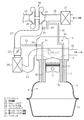
以下、本発明の実施形態を図1に従って説明する。先ず、内燃機関の構成について説明する。
図1に示すように、内燃機関のシリンダブロック10は、複数(例えば4つ)の円筒状の気筒10aを有している。なお、図1では、気筒10aを1つのみ図示している。気筒10aの内部には、気筒10a内を往復動作するピストン11が設けられている。シリンダブロック10の上部には、シリンダヘッド12が取り付けられている。シリンダヘッド12には、気筒10aに吸気を供給するための吸気ポート12a、及び気筒10aから排気を排出するための排気ポート12bが設けられている。また、シリンダヘッド12には、吸気ポート12a及び排気ポート12bを開閉する図示しないバルブ機構が設けられている。シリンダヘッド12の上部には、バルブ機構等を覆うヘッドカバー13が取り付けられている。
Hereinafter, an embodiment of the present invention will be described with reference to FIG. First, the configuration of the internal combustion engine will be described.
As shown in FIG. 1, the
シリンダブロック10の下部には、ピストン11の往復動作によって回転させられるクランクシャフトを収容するクランクケース14が取り付けられている。クランクケース14の下部には、エンジンオイルを貯留するオイルパン15が取り付けられている。これらクランクケース14及びオイルパン15によって、クランクケース14の内部がクランクルームRとして区画されている。クランクルームR内には、気筒10aの内部から漏れだした未燃焼ガス等がブローバイガスとして存在する。
A
シリンダヘッド12における吸気ポート12aには吸気通路20が接続されており、排気ポート12bには排気通路29が接続されている。吸気通路20には、吸気中の異物を濾過して除去するエアクリーナ21が設けられている。吸気通路20におけるエアクリーナ21よりも下流側には、過給器40のコンプレッサ41が設けられている。なお、過給器40は、いわゆる排気駆動式の過給器であり、排気通路29にタービン42が設けられている。そして、排気通路29を流通する排気の流れによってタービン42が回転することによりコンプレッサ41が回転して、過給器40のコンプレッサ41が高圧の吸気を下流側に供給する。
An
吸気通路20におけるコンプレッサ41よりも下流側には、スロットルバルブ22が設けられている。スロットルバルブ22は、アクセルペダルの操作量、車両の速度などに応じて図示しない電子制御ユニット(ECU)によって開度が制御される。吸気通路20におけるスロットルバルブ22よりも下流側には、吸気を冷却するためのインタークーラ23が設けられている。吸気通路20におけるインタークーラ23の下流側は、シリンダヘッド12の吸気ポート12aに接続されている。
A
吸気通路20におけるエアクリーナ21よりも下流側であって過給器40のコンプレッサ41よりも上流側と、コンプレッサ41よりも下流側であってスロットルバルブ22よりも上流側とには、エアバイパス通路24が接続されている。すなわち、エアバイパス通路24は、過給器40のコンプレッサ41を迂回する通路である。エアバイパス通路24の流路断面積は、吸気通路20におけるエアクリーナ21から過給器40のコンプレッサ41までの部分の流路断面積よりも小さくなっている。
An
エアバイパス通路24には、当該エアバイパス通路24を開閉するエアバイパスバルブ25が設けられている。エアバイパスバルブ25は、電子制御ユニットによって開閉制御される電磁式の弁である。エアバイパスバルブ25は、吸気通路20におけるコンプレッサ41よりも下流側であってスロットルバルブ22よりも上流側の圧力が、吸気通路20におけるコンプレッサ41よりも上流側の圧力に対して所定値以上高くなったときに開弁する。内燃機関が過給域で運転している状態で、スロットルバルブ22の開度が所定の開度以下になると、コンプレッサ41よりも下流側であってスロットルバルブよりも上流側の圧力が、コンプレッサ41よりも上流側の圧力に対して所定値以上高くなる。そこで、この実施形態では、内燃機関が過給域で運転している状態で、スロットルバルブ22の開度が所定の開度以下になったときに、エアバイパスバルブ25を開弁制御する。
The
この実施形態の内燃機関は、クランクケース14の内部空間であるクランクルームR内に連通する第1ブローバイガス通路31、及び第2ブローバイガス通路36を備えている。第1ブローバイガス通路31は、シリンダブロック10及びシリンダヘッド12の内部を貫通する第1ブロック内通路32と、第1ブロック内通路32に接続された第1管部材33とで構成されている。第1ブロック内通路32は、クランクルームR内に開口し、シリンダブロック10及びシリンダヘッド12を貫通して、ヘッドカバー13内にまで延びている。第1ブロック内通路32のヘッドカバー13側の開口には、第1管部材33の一端が接続されている。第1管部材33の他端側はヘッドカバー13の外部に引き出されている。第1管部材33の他端は、吸気通路20におけるコンプレッサ41の下流側であってスロットルバルブ22の上流側に接続されている。また、第1管部材33には、PCVバルブ34(Positive Crankcase Ventilationバルブ)が設けられている。PCVバルブ34は、クランクルームR側から吸気通路20側へと気体が流通することを許容し、吸気通路20側からクランクルームR側へと気体が流通することを禁止する逆止弁である。
The internal combustion engine of this embodiment includes a first blow-by
第2ブローバイガス通路36は、シリンダブロック10及びシリンダヘッド12の内部を貫通する第2ブロック内通路37と、第2ブロック内通路37に接続された第2管部材38とで構成されている。第2ブロック内通路37は、クランクルームR内に開口し、シリンダブロック10及びシリンダヘッド12を貫通して、ヘッドカバー13内にまで延びている。第2ブロック内通路37のヘッドカバー13側の開口には、第2管部材38の一端が接続されている。第2管部材38の他端側はヘッドカバー13の外部に引き出されている。そして、第2管部材38の他端は、エアバイパス通路24に接続されている。なお、上述したとおり、エアバイパス通路24は、吸気通路20におけるスロットルバルブ22よりも上流側に接続されている。したがって、エアバイパス通路24に接続されている第2ブローバイガス通路36(第2管部材38)も、吸気通路20におけるスロットルバルブ22よりも上流側に接続されていることになる。
The second blow-by
次に、上記構成の内燃機関における吸気及びブローバイガスの流れについて説明する。先ず、内燃機関が自然吸気域で運転している場合について説明する。
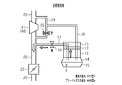
図2に示すように、内燃機関が自然吸気域で運転している場合には、吸気通路20の上流側から下流側へと吸気が流れる。このとき、吸気通路20におけるコンプレッサ41よりも上流側の圧力とコンプレッサ41よりも下流側の圧力との差は小さい。そのため、エアバイパス通路24に設けられているエアバイパスバルブ25が閉弁されている。
Next, the flow of intake air and blow-by gas in the internal combustion engine having the above configuration will be described. First, the case where the internal combustion engine is operating in the natural intake region will be described.
As shown in FIG. 2, when the internal combustion engine is operating in a natural intake region, intake air flows from the upstream side to the downstream side of the
一方、内燃機関が自然吸気域で運転している場合には、コンプレッサ41において吸気が圧縮されない。そのため、吸気通路20におけるコンプレッサ41よりも下流側の吸気の圧力は、ピストン11の往復動作に伴って、大気圧に対して負圧になる。これに対して、クランクケース14とオイルパン15とで区画されるクランクルームR内の圧力は、略大気圧である。また、PCVバルブ34は、クランクルームR側から吸気通路20側へと気体が流れることを許容する(開弁する)。したがって、ブローバイガスが、第1ブローバイガス通路31を介してクランクルームRから吸気通路20へと供給される。
On the other hand, when the internal combustion engine is operating in the natural intake region, the intake air is not compressed by the
次に、内燃機関が過給域で運転している場合について説明する。
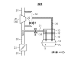
図3に示すように、内燃機関が過給域で運転している場合には、吸気通路20におけるコンプレッサ41の下流側に圧縮された吸気が供給される。とはいえ、内燃機関が過給域で運転している場合には、スロットルバルブ22の開度が大きくなっている蓋然性が高い。そのため、吸気通路20におけるコンプレッサ41の下流側の吸気は、速やかにシリンダブロック10の各気筒10aに供給される。したがって、吸気通路20におけるコンプレッサ41の下流側の圧力が過度に大きくなることはなく、吸気通路20におけるコンプレッサ41の下流側の圧力が、上流側の圧力よりも所定値以上高くなることはない。その結果、エアバイパスバルブ25は閉弁されたままである。
Next, the case where the internal combustion engine is operating in the supercharging region will be described.
As shown in FIG. 3, when the internal combustion engine is operating in the supercharging region, the compressed intake air is supplied to the downstream side of the
また、エアバイパスバルブ25が閉弁されていると、エアバイパス通路24内において吸気が流通しないので、当該エアバイパス通路24に接続されている第2ブローバイガス通路36を介して、多くのブローバイガスを吸気通路20へと供給することは期待できない。
Further, when the
一方、内燃機関が過給域で運転している場合には、吸気通路20におけるコンプレッサ41よりも下流側の圧力は大気圧よりも高い。これに対して、クランクケース14とオイルパン15とで区画されるクランクルームR内の圧力は、略大気圧である。ここで、PCVバルブ34は、吸気通路20からクランクルームRへと気体が流れることを禁止する(閉弁する)逆止弁である。したがって、内燃機関が過給域で運転している場合には、吸気通路20側から第1ブローバイガス通路31を介してクランクルームR内へと吸気が供給されることはないし、クランクルームRから吸気通路20へとブローバイガスが供給されることもない。
On the other hand, when the internal combustion engine is operating in the supercharging region, the pressure downstream of the
次に、内燃機関において過給域から自然吸気域に切り替えた場合について説明する。
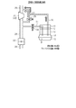
図4に示すように、内燃機関の運転状態が過給域から自然吸気域に切り替えられたときには、スロットルバルブ22の開度が小さくなる。その一方で、過給器40のコンプレッサ41は、慣性によってしばらく回転し続けるため、吸気通路20におけるコンプレッサ41よりも下流側であってスロットルバルブ22よりも上流側の圧力は相応に高くなる。その結果、吸気通路20におけるコンプレッサ41よりも下流側であってスロットルバルブ22よりも上流側の圧力が、吸気通路20におけるコンプレッサ41よりも上流側の圧力よりも所定値以上高くなる蓋然性が高い。
Next, the case where the internal combustion engine is switched from the supercharging region to the natural intake region will be described.
As shown in FIG. 4, when the operating state of the internal combustion engine is switched from the supercharging region to the natural intake region, the opening degree of the
ここで、上記実施形態の内燃機関では、内燃機関が過給域で運転している状態で、スロットルバルブ22の開度が所定の開度以下になったときには、エアバイパスバルブ25が開弁される。したがって、吸気通路20におけるコンプレッサ41よりも下流側の吸気が、エアバイパス通路24を介してコンプレッサ41よりも上流側へと供給される。また、エアバイパス通路24の流路断面積は、吸気通路20の流路断面積よりも小さい。そのため、エアバイパス通路24内を流通する吸気の速度は相応の速度になるとともに、そのときのエアバイパス通路24内の静圧は、大気圧よりも低くなる。その結果、第2ブローバイガス通路36及びエアバイパス通路24を介して、クランクルームRから吸気通路20におけるコンプレッサ41よりも上流側に、ブローバイガスが供給される。
Here, in the internal combustion engine of the above embodiment, the
一方、上述したとおり、吸気通路20におけるコンプレッサ41よりも下流側であってスロットルバルブ22よりも上流側の圧力は、大気圧よりも高い状態にある。そして、PCVバルブ34は、吸気通路20側からクランクルームR側と気体が流れることを禁止する(閉弁する)逆止弁である。したがって、内燃機関の運転状態が過給域から自然吸気域に切り替えられた直後は、吸気通路20側から第1ブローバイガス通路31を介してクランクルームR側へと吸気が供給されることはないし、クランクルームRから吸気通路20へとブローバイガスが供給されることもない。
On the other hand, as described above, the pressure in the
上記のとおり構成された内燃機関の効果について説明する。
先ず、上記実施形態の内燃機関は、第1ブローバイガス通路31及び第2ブローバイガス通路36が、いずれも吸気通路20におけるスロットルバルブ22よりも上流側に接続されている。それゆえ、仮に、ブローバイガス通路が吸気通路20におけるスロットルバルブ22よりも下流側に接続されている場合に比較して、ブローバイガス通路からシリンダヘッド12の吸気ポート12aまでの距離が長くなる。そのため、仮にブローバイガスに異物が含まれていても、ブローバイガス通路が吸気通路20におけるスロットルバルブ22よりも下流側に接続されている場合に比較して、シリンダヘッド12の吸気ポート12aや当該吸気ポート12aを開閉する吸気バルブに異物がデポジットとして堆積しにくい。
The effect of the internal combustion engine configured as described above will be described.
First, in the internal combustion engine of the above embodiment, the first blow-by
なお、第1ブローバイガス通路31や第2ブローバイガス通路36が吸気通路20におけるスロットルバルブ22よりも上流側に接続されていることにより、スロットルバルブ22やインタークーラ23に異物がデポジットとして堆積するおそれはある。とはいえ、一般に、スロットルバルブ22は、電子制御ユニットによって学習制御されており、仮にスロットルバルブ22にデポジットが堆積したとしても、そのデポジットの影響を学習して適切に制御される。また、インタークーラ23に多少のデポジットが堆積したとしても、内燃機関の運転状態に大きな影響を与えるとは考えにくい。このように、シリンダヘッド12の吸気ポート12aや吸気バルブにデポジットが堆積する場合よりも、スロットルバルブ22やインタークーラ23にデポジットが堆積する場合の方が、内燃機関に与える悪影響は小さくて済む。
Since the first blow-by
ところで、内燃機関が過給域で運転している際には、上述したとおり、第1ブローバイガス通路31及び第2ブローバイガス通路36を介してブローバイガスを吸気通路20へと供給することができない。そのため、内燃機関が過給域で運転している場合には、クランクケース14とオイルパン15とで区画されるクランクルームR内に多くのブローバイガスが滞留していることがある。
By the way, when the internal combustion engine is operating in the supercharging region, blow-by gas cannot be supplied to the
その一方で、内燃機関が自然吸気域で運転している際に吸気通路20に発生する負圧の程度は、スロットルバルブ22の下流側よりも上流側のほうが小さい(圧力が大きい)。上記実施形態では、第1ブローバイガス通路31が吸気通路20におけるスロットルバルブ22よりも上流側に接続されている。そのため、第1ブローバイガス通路31が吸気通路20におけるスロットルバルブ22よりも下流側に接続されている場合に比較して、内燃機関が自然吸気域で運転している際に、第1ブローバイガス通路31を介して吸気通路20へと至るブローバイガスの流速が遅い。その結果、内燃機関が自然吸気域で運転しているときに、第1ブローバイガス通路31を介してブローバイガスを吸気通路20に供給するのみでは、クランクルームR内のブローバイガスを適切に掃気するのに相応の時間が必要となってしまう。
On the other hand, the degree of negative pressure generated in the
この点、上述したとおり、上記実施形態では、第2ブローバイガス通路36がエアバイパス通路24に接続されている。そして、内燃機関の運転状態が過給域から自然吸気域に切り替わったときに、エアバイパス通路24を高速で流通する吸気の流れを利用して、第2ブローバイガス通路36を介して、ブローバイガスをクランクルームRから吸気通路20へと供給している。したがって、内燃機関が過給域で運転している際に多くのブローバイガスがクランクルームRに滞留していても、そのブローバイガスの多くを、内燃機関の運転状態が過給域から自然吸気域に切り替わったときに吸気通路20へと供給できる。
In this regard, as described above, the second blow-by
その後、内燃機関は自然吸気域で運転することになるが、この時点では、過給域で運転していた際に滞留していたブローバイガスの多くが既に掃気されている。したがって、第1ブローバイガス通路31がスロットルバルブ22よりも上流に接続されていて、第1ブローバイガス通路31を介したブローバイガスの流速が遅くとも、適切にクランクルームR内のブローバイガスを掃気できる。
After that, the internal combustion engine is operated in the natural intake region, but at this time, much of the blow-by gas that has accumulated during operation in the supercharging region has already been scavenged. Therefore, even if the first blow-by
上記実施形態は、以下のように変更できる。
・インタークーラ23は、吸気通路におけるスロットルバルブ22よりも上流側に設けられていてもよい。この変更例の場合、第1ブローバイガス通路31がスロットルバルブ22よりも上流に接続されているのならば、インタークーラ23の上流側に第1ブローバイガス通路31が接続されていてもよいし、インタークーラ23の下流側に第1ブローバイガス通路31が接続されていてもよい。
The above embodiment can be modified as follows.
The
・上記実施形態では、内燃機関が過給域で運転している状態で、スロットルバルブ22の開度が所定の開度以下になったときに、エアバイパスバルブ25を開弁するように制御していたが、エアバイパスバルブ25の制御方法はこれに限らない。例えば、吸気通路20における過給器40のコンプレッサ41の下流側の圧力と上流側の圧力とを圧力センサで検出し、その検出値の差が所定値以上になったときに開弁するように制御してもよい。
In the above embodiment, when the internal combustion engine is operating in the supercharging region, the
・エアバイパスバルブ25は、電子制御ユニットによって開閉制御される電磁式の弁に限らない。例えば、吸気通路20における過給器40のコンプレッサ41の下流側の圧力と上流側の圧力との差が所定の圧力以上になったときに開弁する差圧動作弁であってもよい。
The
・第1ブローバイガス通路31の構成は、上記実施形態で例示したものに限らない。例えば、第1ブローバイガス通路31における第1ブロック内通路32を省略して、第1管部材33をクランクケース14やオイルパン15に直接接続してもよい。
-The structure of the 1st blow-by
・第2ブローバイガス通路36についても同様であり、例えば、第2ブローバイガス通路36における第2ブロック内通路37を省略して、第2管部材38をクランクケース14やオイルパン15に直接接続してもよい。
The same applies to the second blow-by
・第1ブローバイガス通路31及び第2ブローバイガス通路36は、独立した2つの通路でなくてもよく、一部分が共通化されていてもよい。例えば、1つのブロック内通路に第1管部材33及び第2管部材38を接続してもよい。なお、この場合、ブロック内通路は、第1ブローバイガス通路31の一部分と第2ブローバイガス通路36の一部分とを兼ねることになる。
-The 1st blow-by
・ヘッドカバー13の内部を、第1ブローバイガス通路31や第2ブローバイガス通路36の一部分として構成してもよい。具体的には、第1ブローバイガス通路31における第1管部材33を第1ブロック内通路32に接続するのではなく、ヘッドカバー13に接続してもよい。この場合、第1ブローバイガス通路31は、第1ブロック内通路32、ヘッドカバー13の内部、第1管部材33で構成されることになる。この点、第2ブローバイガス通路についても同様である。
The interior of the
・第1ブローバイガス通路31及び第2ブローバイガス通路36の途中に、ブローバイガス中の燃料を凝集させるオイルセパレータを設けてもよい。なお、オイルセパレータは、シリンダブロック10の内部(第1ブロック内通路32や第2ブロック内通路37の途中)に設けてもよいし、ヘッドカバー13の内部に設けてもよい。
An oil separator that agglomerates the fuel in the blow-by gas may be provided in the middle of the first blow-by
・PCVバルブ34を、電子制御ユニットによって開閉制御される電磁式の弁で構成してもよい。この場合、図2〜図4に示すように、内燃機関が自然吸気域で運転している場合にはPCVバルブ34が開弁され、内燃機関が過給域で運転している場合や、内燃機関の運転状態が過給域から自然吸気域に切り替わった時にはPCVバルブ34が閉弁されるように制御することが好ましい。
The
R…クランクルーム、10…シリンダブロック、10a…気筒、11…ピストン、12…シリンダヘッド、12a…吸気ポート、12b…排気ポート、13…ヘッドカバー、14…クランクケース、15…オイルパン、20…吸気通路、21…エアクリーナ、22…スロットルバルブ、23…インタークーラ、24…エアバイパス通路、25…エアバイパスバルブ、29…排気通路、31…第1ブローバイガス通路、32…第1ブロック内通路、33…第1管部材、34…PCVバルブ、36…第2ブローバイガス通路、37…第2ブロック内通路、38…第2管部材、40…過給器、41…コンプレッサ、42…タービン。 R ... Crankroom, 10 ... Cylinder block, 10a ... Cylinder, 11 ... Piston, 12 ... Cylinder head, 12a ... Intake port, 12b ... Exhaust port, 13 ... Head cover, 14 ... Crankcase, 15 ... Oil pan, 20 ... Intake Passage, 21 ... Air cleaner, 22 ... Throttle valve, 23 ... Intercooler, 24 ... Air bypass passage, 25 ... Air bypass valve, 29 ... Exhaust passage, 31 ... First blow-by gas passage, 32 ... First block internal passage, 33 ... 1st pipe member, 34 ... PCV valve, 36 ... 2nd blow-by gas passage, 37 ... 2nd block internal passage, 38 ... 2nd pipe member, 40 ... Supercharger, 41 ... Compressor, 42 ... Turbine.
Claims (1)
前記エアバイパス通路には、前記吸気通路における前記コンプレッサよりも下流側であって前記スロットルバルブよりも上流側の圧力が、前記吸気通路におけるコンプレッサよりも上流側の圧力に対して所定値以上高くなったときに開弁するエアバイパスバルブが設けられ、
前記吸気通路における前記コンプレッサよりも下流側であって前記スロットルバルブよりも上流側には、前記クランクケースの内部に連通する第1ブローバイガス通路が接続され、
前記エアバイパス通路には、前記クランクケースの内部に連通する第2ブローバイガス通路が接続されている
ことを特徴とする内燃機関。 A cylinder block having a cylinder; a crankcase attached to a lower portion of the cylinder block; a cylinder head attached to an upper portion of the cylinder block and provided with an intake port for supplying intake air to the cylinder; and the intake air An intake passage connected to a port; a supercharger provided with a compressor in the intake passage; an air bypass passage connecting the upstream and downstream sides of the compressor in the intake passage to bypass the compressor; An internal combustion engine comprising a throttle valve provided at a portion downstream of a connection portion of the compressor and the air bypass passage in the intake passage;
In the air bypass passage, the pressure in the intake passage downstream of the compressor and upstream of the throttle valve is higher than a predetermined value by a predetermined value relative to the pressure in the intake passage upstream of the compressor. An air bypass valve that opens when the
A first blow-by gas passage communicating with the interior of the crankcase is connected to the intake passage downstream of the compressor and upstream of the throttle valve.
An internal combustion engine characterized in that a second blow-by gas passage communicating with the inside of the crankcase is connected to the air bypass passage.
Priority Applications (1)
| Application Number | Priority Date | Filing Date | Title |
|---|---|---|---|
| JP2016084440A JP6508113B2 (en) | 2016-04-20 | 2016-04-20 | Internal combustion engine |
Applications Claiming Priority (1)
| Application Number | Priority Date | Filing Date | Title |
|---|---|---|---|
| JP2016084440A JP6508113B2 (en) | 2016-04-20 | 2016-04-20 | Internal combustion engine |
Publications (2)
| Publication Number | Publication Date |
|---|---|
| JP2017194009A true JP2017194009A (en) | 2017-10-26 |
| JP6508113B2 JP6508113B2 (en) | 2019-05-08 |
Family
ID=60155340
Family Applications (1)
| Application Number | Title | Priority Date | Filing Date |
|---|---|---|---|
| JP2016084440A Expired - Fee Related JP6508113B2 (en) | 2016-04-20 | 2016-04-20 | Internal combustion engine |
Country Status (1)
| Country | Link |
|---|---|
| JP (1) | JP6508113B2 (en) |
Cited By (1)
| Publication number | Priority date | Publication date | Assignee | Title |
|---|---|---|---|---|
| GB2625090A (en) * | 2022-12-05 | 2024-06-12 | Jcb Res | Internal combustion engine |
Citations (6)
| Publication number | Priority date | Publication date | Assignee | Title |
|---|---|---|---|---|
| JPS599126U (en) * | 1982-07-08 | 1984-01-20 | トヨタ自動車株式会社 | Crankcase forced circulation system for internal combustion engine with turbocharger |
| JP2009299645A (en) * | 2008-06-17 | 2009-12-24 | Aisan Ind Co Ltd | Blowby gas returning device |
| JP2011094557A (en) * | 2009-09-30 | 2011-05-12 | Aisan Industry Co Ltd | Blow-by gas refluxing device |
| JP2014092070A (en) * | 2012-11-02 | 2014-05-19 | Toyota Motor Corp | Blow-by gas treatment device |
| JP2014122567A (en) * | 2012-12-20 | 2014-07-03 | Nippon Soken Inc | Crank case ventilator |
| JP2015040549A (en) * | 2013-08-23 | 2015-03-02 | 愛三工業株式会社 | Internal combustion engine with supercharger |
-
2016
- 2016-04-20 JP JP2016084440A patent/JP6508113B2/en not_active Expired - Fee Related
Patent Citations (6)
| Publication number | Priority date | Publication date | Assignee | Title |
|---|---|---|---|---|
| JPS599126U (en) * | 1982-07-08 | 1984-01-20 | トヨタ自動車株式会社 | Crankcase forced circulation system for internal combustion engine with turbocharger |
| JP2009299645A (en) * | 2008-06-17 | 2009-12-24 | Aisan Ind Co Ltd | Blowby gas returning device |
| JP2011094557A (en) * | 2009-09-30 | 2011-05-12 | Aisan Industry Co Ltd | Blow-by gas refluxing device |
| JP2014092070A (en) * | 2012-11-02 | 2014-05-19 | Toyota Motor Corp | Blow-by gas treatment device |
| JP2014122567A (en) * | 2012-12-20 | 2014-07-03 | Nippon Soken Inc | Crank case ventilator |
| JP2015040549A (en) * | 2013-08-23 | 2015-03-02 | 愛三工業株式会社 | Internal combustion engine with supercharger |
Cited By (1)
| Publication number | Priority date | Publication date | Assignee | Title |
|---|---|---|---|---|
| GB2625090A (en) * | 2022-12-05 | 2024-06-12 | Jcb Res | Internal combustion engine |
Also Published As
| Publication number | Publication date |
|---|---|
| JP6508113B2 (en) | 2019-05-08 |
Similar Documents
| Publication | Publication Date | Title |
|---|---|---|
| JP4297175B2 (en) | Blow-by gas processing equipment | |
| JP5964285B2 (en) | Internal combustion engine | |
| JP6765260B2 (en) | Blow-by gas processing device for internal combustion engine with supercharger | |
| JP2009293464A (en) | Blow-by gas recirculating device for engine with supercharger | |
| US8844507B2 (en) | PCV system for internal combustion engine | |
| JP2003013723A (en) | Blow-by gas separator | |
| JP5822445B2 (en) | Blowby gas recirculation system | |
| JP2001020715A (en) | Exhaust device provided in internal combustion engine | |
| JP2013117176A (en) | Blowby gas reduction device and abnormality diagnosing method of blowby gas reduction device | |
| US8000879B2 (en) | Method for operating a two-stroke engine | |
| JP2003184532A (en) | Crankcase ventilation system for exhaust turbocharged internal combustion engine | |
| JP5664474B2 (en) | Crankcase ventilation device for internal combustion engine | |
| JP2013096229A (en) | Blowby gas recirculation device | |
| US20120304971A1 (en) | Engine including crankcase ventilation system oil drain features | |
| JP6508113B2 (en) | Internal combustion engine | |
| JP2017044077A (en) | Exhaust system for engine | |
| US9243529B2 (en) | Device for processing blow-by from V-type internal combustion engines | |
| KR101496034B1 (en) | A Device of closed crankcase ventilation for vehicle | |
| JP2011236827A (en) | Blow-by gas treatment device of internal combustion engine | |
| JP2020090934A (en) | Internal combustion engine | |
| JPH04292516A (en) | Blowby gas treatment equipment for internal combustion engine | |
| EP2123870A1 (en) | Blowby gas treatment system for multiple cylinder engine | |
| JP2007064155A (en) | Oil mist processing equipment | |
| JP2012237231A (en) | Blowby gas reflux device | |
| JP6984483B2 (en) | Internal combustion engine control device |
Legal Events
| Date | Code | Title | Description |
|---|---|---|---|
| A621 | Written request for application examination |
Free format text: JAPANESE INTERMEDIATE CODE: A621 Effective date: 20180511 |
|
| A977 | Report on retrieval |
Free format text: JAPANESE INTERMEDIATE CODE: A971007 Effective date: 20190222 |
|
| TRDD | Decision of grant or rejection written | ||
| A01 | Written decision to grant a patent or to grant a registration (utility model) |
Free format text: JAPANESE INTERMEDIATE CODE: A01 Effective date: 20190305 |
|
| A61 | First payment of annual fees (during grant procedure) |
Free format text: JAPANESE INTERMEDIATE CODE: A61 Effective date: 20190318 |
|
| R151 | Written notification of patent or utility model registration |
Ref document number: 6508113 Country of ref document: JP Free format text: JAPANESE INTERMEDIATE CODE: R151 |
|
| LAPS | Cancellation because of no payment of annual fees |