JP2017194076A - Electromagnetic spring clutch - Google Patents
Electromagnetic spring clutch Download PDFInfo
- Publication number
- JP2017194076A JP2017194076A JP2016082751A JP2016082751A JP2017194076A JP 2017194076 A JP2017194076 A JP 2017194076A JP 2016082751 A JP2016082751 A JP 2016082751A JP 2016082751 A JP2016082751 A JP 2016082751A JP 2017194076 A JP2017194076 A JP 2017194076A
- Authority
- JP
- Japan
- Prior art keywords
- peripheral surface
- input
- spring
- outer peripheral
- hub
- Prior art date
- Legal status (The legal status is an assumption and is not a legal conclusion. Google has not performed a legal analysis and makes no representation as to the accuracy of the status listed.)
- Pending
Links
Images
Landscapes
- Mechanical Operated Clutches (AREA)
Abstract
【課題】電磁スプリングクラッチの接続時に発生するショックトルクを低減できるようにする。【解決手段】入力軸2と、インプットロータ4と、アウトプットハブ6と、インプットロータ4の外周面4Bとアウトプットロータ6の外周面6Bの径方向外側に巻回された状態で配置され、縮径されることにより外周面4Bと外周面6Bとを外周側から巻き締めて、インプットロータ4とアウトプットハブ6との間のトルク伝達を可能にするスプリング7と、スプリング7の一端が係合され、インプットロータ4に一体回転可能に吸着されるアーマチュア5と、を備え、スプリング7の線材8は、外周面4B又は外周面6Bと面接触可能な接触内周面8Aを有し、軸を含む面での断面における接触内周面8Aの軸方向の長さが、断面での軸方向の最大幅よりも短くなるように形成する。【選択図】図1A shock torque generated when an electromagnetic spring clutch is connected can be reduced. An input shaft 2, an input rotor 4, an output hub 6, and an outer peripheral surface 4B of the input rotor 4 and an outer peripheral surface 6B of the output rotor 6 are disposed in a state of being wound radially outward. By reducing the diameter, the outer peripheral surface 4B and the outer peripheral surface 6B are wound from the outer peripheral side to enable torque transmission between the input rotor 4 and the output hub 6, and one end of the spring 7 is engaged. The wire rod 8 of the spring 7 has a contact inner peripheral surface 8A that can come into surface contact with the outer peripheral surface 4B or the outer peripheral surface 6B. The axial length of the contact inner peripheral surface 8A in the cross-section including the surface is shorter than the maximum axial width in the cross-section. [Selection] Figure 1
Description
本発明は、入力側と出力側とをスプリングの巻き締め力により連結する電磁スプリングクラッチに関する。 The present invention relates to an electromagnetic spring clutch that connects an input side and an output side by a tightening force of a spring.
従来、トラック等の車両には、エンジンやモータ等の動力源による駆動力を車両の架装物を駆動させる動力として出力するための動力出力機構(PTO)が設けられているものがある。動力出力機構には、動力源から架装物側への駆動力の断接を行うための電磁スプリングクラッチが設けられているものがある。 Conventionally, some vehicles such as trucks are provided with a power output mechanism (PTO) for outputting a driving force from a power source such as an engine or a motor as power for driving a vehicle bodywork. Some power output mechanisms are provided with an electromagnetic spring clutch for connecting and disconnecting a driving force from a power source to the bodywork side.
電磁スプリングクラッチに関する技術としては、コイルバネを略三角形あるいはほぼ台形の断面する線材を三角形または台形の底辺が内側となる様に巻回させることにより、コイルばねの締結に必要な荷重を軽減し、コイルばねの縮径動作をスムースにする技術が知られている(例えば、特許文献1参照)。 As a technology related to the electromagnetic spring clutch, the coil spring is wound with a wire having a substantially triangular or substantially trapezoidal cross section so that the bottom of the triangle or trapezoid is inside, thereby reducing the load necessary for fastening the coil spring, A technique for smoothly reducing the diameter-reducing operation of a spring is known (for example, see Patent Document 1).
電磁スプリングクラッチを接続する際には、スプリングが捩られることにより縮径されて、入力ハブと出力ハブとの外周面を巻き締めることにより、入力ハブと出力ハブとが連結される。このように電磁スプリングクラッチを接続する際には、一時的に過大なトルク(ショックトルク)が発生する。 When the electromagnetic spring clutch is connected, the diameter is reduced by twisting the spring, and the input hub and the output hub are connected by tightening the outer peripheral surfaces of the input hub and the output hub. When the electromagnetic spring clutch is connected in this way, excessive torque (shock torque) is temporarily generated.
このショックトルクは、異音を発生させたり、電磁スプリングクラッチの入力軸に動力を伝達するためのギヤ等の動力伝達部材に損傷を発生させたりする虞がある。このようなショックトルクの影響を防止するために、動力伝達部材に対して表面処理を施したり、動力伝達部材の材質を変えたりすることが行われる。 This shock torque may cause abnormal noise or damage a power transmission member such as a gear for transmitting power to the input shaft of the electromagnetic spring clutch. In order to prevent the influence of such shock torque, the power transmission member is subjected to a surface treatment or the material of the power transmission member is changed.
更に、このショックトルクは、電磁スプリンククラッチを接続した回数が増加するほど大きくなることが判明した。このため、電磁スプリングクラッチの接続を繰り返し行うことにより増加するショックトルクを想定して、動力伝達部材の材質等を考慮しなければならない。増加するショックトルクを想定した動力伝達部材を用意するようにすると、コストが大幅に増加してしまう問題がある。 Further, it has been found that this shock torque increases as the number of times the electromagnetic sprink clutch is engaged increases. For this reason, it is necessary to consider the material and the like of the power transmission member, assuming a shock torque that increases by repeatedly connecting the electromagnetic spring clutch. If a power transmission member that assumes an increasing shock torque is prepared, there is a problem in that the cost increases significantly.
そこで、本発明は、電磁スプリングクラッチの接続時に発生するショックトルクを低減することができる技術を提供することを目的とする。 Then, an object of this invention is to provide the technique which can reduce the shock torque which generate | occur | produces at the time of the connection of an electromagnetic spring clutch.
上記した目的を達成するため、本発明の一観点に係る電磁スプリングクラッチは、動力が入力される入力軸と、入力軸に相対回転不能に固定され、入力軸の軸方向の延びる入力側外周面を有する入力ハブと、入力ハブと同軸に配置され、入力軸の軸方向に延びる出力側外周面を有する出力ハブと、入力ハブの入力側外周面と出力ハブの出力側外周面の径方向外側に巻回された状態で配置され、縮径されることにより入力ハブの入力側外周面と出力ハブの出力側外周面とを外周側から締め付けて、入力ハブと出力ハブとの間のトルク伝達を可能にするスプリングと、スプリングの一端が係合され、電磁力により前記入力ハブに吸着され、摩擦力により前記入力ハブと同方向に回転可能となるアーマチュアと、を備え、スプリングの線材は、入力側外周面又は出力側外周面と面接触可能な接触内周面を有し、線材の入力側外周面と面接触可能な接触内周面を有する範囲の少なくとも一部分において、軸を含む面での断面における接触内周面の軸方向の長さが、断面での軸方向の最大幅よりも短くなるように形成されている。 In order to achieve the above-described object, an electromagnetic spring clutch according to an aspect of the present invention includes an input shaft to which power is input, and an input-side outer peripheral surface that is fixed to the input shaft so as not to be relatively rotatable and extends in the axial direction of the input shaft. An output hub having an output outer peripheral surface that is coaxially arranged with the input hub and extends in the axial direction of the input shaft, and an outer side in the radial direction of the input outer peripheral surface of the input hub and the output outer peripheral surface of the output hub Torque transmission between the input hub and the output hub is achieved by tightening the input side outer peripheral surface of the input hub and the output outer peripheral surface of the output hub from the outer peripheral side by being reduced in diameter. And an armature that is engaged with one end of the spring, is attracted to the input hub by electromagnetic force, and is rotatable in the same direction as the input hub by frictional force. input A cross-section at the surface including the shaft in at least a part of the range having a contact inner peripheral surface that can be in surface contact with the outer peripheral surface or the output-side outer peripheral surface, and a contact inner peripheral surface that can be in surface contact with the input-side outer peripheral surface of the wire Is formed so that the axial length of the contact inner peripheral surface is shorter than the maximum axial width of the cross section.
上記電磁スプリングクラッチにおいて、線材の入力側外周面と面接触可能な接触内周面を有する範囲の少なくとも一部分において、接触内周面の軸方向の長さが、断面での外周の軸方向の長さよりも短くなるように形成されていてもよい。 In the electromagnetic spring clutch, the axial length of the contact inner peripheral surface is the axial length of the outer periphery in the cross section in at least a part of the range having the contact inner peripheral surface capable of surface contact with the input-side outer peripheral surface of the wire. You may form so that it may become shorter.
また、上記電磁スプリングクラッチにおいて、スプリングの線材は、線材の入力側外周面と面接触可能な前記接触内周面を有する範囲の少なくとも一部分において、接触内周面が、断面における軸方向の一端側の端部よりも他端側且つ断面における軸方向の他端側の端部よりも一端側に位置するように形成されていてもよい。 Further, in the electromagnetic spring clutch, the contact inner peripheral surface is at one end side in the axial direction in the cross section in at least a part of the range in which the wire of the spring has the contact inner peripheral surface capable of surface contact with the input outer peripheral surface of the wire. It may be formed so as to be located on the other end side from the other end portion and on the one end side from the end portion on the other end side in the axial direction in the cross section.
本発明によれば、電磁スプリングクラッチの接続時に発生するショックトルクを低減することができる。 According to the present invention, it is possible to reduce the shock torque generated when the electromagnetic spring clutch is connected.
以下、添付図面に基づいて、本発明の一実施形態に係る電磁スプリングクラッチを説明する。同一の部品には同一の符号を付してあり、それらの名称および機能も同じである。したがって、それらについての詳細な説明は繰返さない。 Hereinafter, based on an accompanying drawing, an electromagnetic spring clutch concerning one embodiment of the present invention is explained. The same parts are denoted by the same reference numerals, and their names and functions are also the same. Therefore, detailed description thereof will not be repeated.
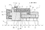
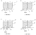
図1は、本発明の一実施形態に係る電磁スプリングクラッチの上半分を示す模式的な断面図である。図3(A)は、本発明の一実施形態に係るスプリングの線材及びインプットロータ(アウトプットハブ)の一部断面図である。 FIG. 1 is a schematic cross-sectional view showing an upper half of an electromagnetic spring clutch according to an embodiment of the present invention. FIG. 3A is a partial cross-sectional view of a spring wire and an input rotor (output hub) according to an embodiment of the present invention.
電磁スプリングクラッチ1は、入力軸2と、磁力発生部3と、入力ハブの一例としてのインプットロータ4と、アーマチュア5と、出力ハブの一例としてのアウトプットハブ6と、スプリング7と、スプリングカバー9と、アダプター10とを備える。
The
入力軸2は、図示しないベアリングにより回転可能に固定されている。入力軸2には、図示しないエンジン等の動力源からの駆動力がギヤ等を介して伝達されるようになっている。
The
磁力発生部3は、円環状の部材であり、内周側に入力軸2が挿通された状態で図示しないケースに固定される。磁力発生部3は、鉄等の強磁性体の部材により構成された円環状のヨーク3Aと、通電されるとアーマチュア5を引き寄せる磁力を発生させる励磁コイル3Bとを備える。
The
インプットロータ4は、略円筒状の部材であり、入力軸2に一体回転可能に接続される。インプットロータ4は、入力軸2の軸Oに垂直な面であって、磁力発生部3により引き寄せられたアーマチュア5が吸着される吸着面4Aと、外周側にスプリング7が巻回される、軸方向に延びる外周面(入力側外周面)4Bとを有する。
The
アーマチュア5は、インプットロータ4の外周面4Bの外径よりも長い内径を有する円環状の部材であり、例えば、永久磁石又は磁性体で構成される。アーマチュア5は、一方側(図中A側)の面がインプットロータ4の吸着面4Aと対向するように配置される。アーマチュア5は、スプリング7のA方向側の端部の爪部7Aと係合する溝部5Aを有する。アーマチュア5は、磁力発生部3により磁力が発生されていない場合には、インプットロータ4から離れた状態となっている一方、磁力発生部3により磁力が発生されている場合には、A方向に吸引されて、インプットロータ4の吸着面4Aに吸着され、インプットロータ4との間の摩擦力によりインプットロータ4と回転可能な状態となる。アーマチュア5は、インプットロータ4との摩擦力がスプリング7から受けるトルクに勝る場合には、インプットロータ4と一体回転し、インプットロータ4との摩擦力がスプリング7から受けるトルクに劣る場合には、インプットロータ4との間に滑りを発生しながら回転する。
The
アウトプットハブ6は、略円筒状の部材であり、入力軸2の周囲に軸受12,13を介して、回転可能に配置される。アウトプットハブ6は、スプリング7のB方向側の端部の爪部7Bと係合する溝部6Aと、外周側にスプリング7が巻回される、軸方向に延びる外周面(出力側外周面)6Bとを有する。アウトプットハブ6の外周面6Bの外径は、インプットロータ4の外周面4Bの外径と略同じ径となっているが、径が異なっていてもよい。
The
スプリング7は、線材8が巻回されて形成されたスプリングであり、スプリング7の無負荷時の内周の径は、インプットロータ4の外周面4B及びアウトプットハブ6の外周面6Bの径より長くなるように形成されている。スプリング7は、アウトプットハブ6の外周面6B及びインプットロータ4の外周面4Bの径方向外側を取り囲むように配置される。スプリング7のA方向側の端部には、アーマチュア5の溝部5Aと係合するための径方向外側に突出する爪部7Aが形成され、B方向側の端部には、アウトプットハブ6の溝部6Aと係合するための径方向内側に突出する爪部7Bが形成されている。
The
線材8は、外周面4B又は外周面6Bと面接触可能な接触内周面8Aを有する。線材8は、図3(A)に示すように、線材8の外周面4Bと面接触可能な接触内周面8Aを有する範囲の少なくとも一部分(本実施形態では、全接触内周面8A)において、軸Oを含む平面での断面における接触内周面8Aの軸O方向の長さLiが、断面での軸方向の最大幅Lo(例えば、外周の軸方向の長さ)よりも短くなるように形成されている。本実施形態では、接触内周面8Aは、断面におけるA方向側の端部よりもB方向側且つB方向側の端部よりもA方向側に位置するように形成されている。したがって、スプリング7が巻き締められた際に、線材8の一の部分の接触内周面8Aと、隣接して巻回される部分の接触内周面8Aとの間には、線材8がインプットロータ4及びアウトプットハブ6と接触しない隙間Gが存在する。このため、スプリング7とインプットロータ4及びアウトプットハブ6とが内周面全体で接触する場合に比して接触面積を低減することができる。これにより、スプリング7によりインプットロータ4とアウトプットハブ6とを巻き締めた場合において、スプリング7とインプットロータ4及びアウトプットハブ6との間の摩擦力を低減することができる。このように、スプリング7の接触内周面8Aとインプットロータ4との摩擦力が低減すると、スプリング7の接触内周面8Aの摩擦力に基づくアウトプットハブ6側(出力側)に伝達可能な最大のトルクが減少する。
The
ここで、スプリング7を介してインプットロータ4からアウトプットハブ6側に伝達可能なトルクは、インプットロータ4とアーマチュア5との間の摩擦力と、スプリング7とインプットロータ4との間の摩擦力とに起因する。そして、出力側を駆動するために出力側に伝達可能なトルクよりも大きいトルクが掛かってしまった場合においては、スプリング7は、インプットロータ4の周囲を滑る状態となり、且つアーマチュア5がインプットロータ4との間に滑りを発生しながら回転することとなるので、出力側には伝達可能なトルクの範囲内のトルクしか伝達されることがない。
Here, the torque that can be transmitted from the
このため、上記したようにスプリング7とインプットロータ4との摩擦力が低減されると、インプットロータ4とアーマチュア5との間の摩擦力及びスプリング7とインプットロータ4との間の摩擦力に基づく出力側に伝達可能なトルクが低減されるので、スプリング21をアウトプットハブ6に巻き締めて、インプットロータ4とアウトプットハブ6とが完全に結合されるまでの時間を長期化でき、発生するショックトルクを低減することができる。
For this reason, when the frictional force between the
スプリングカバー9は、略円筒状の部材であり、スプリング7のB方向側端部のB方向側と、スプリング7の径方向外側と、アーマチュア5の径方向外側とを取り囲むように配置される。
The
アダプター10は、略円筒状の部材であり、入力軸2の周囲に軸受13,14を介して、回転可能に配置される。アダプター10は、アウトプットハブ6に図示しないボルトにより一体回転可能に接続される。アダプター10には、入力軸2からの駆動力を必要とする駆動部に駆動力を伝達するための部材が接続される。
The
次に、本実施形態に係る電磁スプリングクラッチ1の動作について説明する。
Next, the operation of the
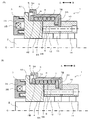
まず、電磁スプリングクラッチ1が断状態である場合、すなわち、入力軸2からの駆動力を出力側(アウトプットハブ6側)に伝達しない場合について説明する。図2(A)は、本発明の一実施形態に係る電磁スプリングクラッチの断状態を示す模式的な断面図である。
First, a case where the
この場合には、磁力発生部3の励磁コイル3Bは、通電されていない状態とされており、アーマチュア5は、インプットロータ4から離れた状態となっている。このため、入力軸2に駆動力が加えられている状態では、入力軸2とインプットロータ4とは一体回転するが、アーマチュア5は回転しない。したがって、スプリング7は縮径されず、スプリング7によるインプットロータ4及びアウトプットハブ6の巻き締めは行われないので、インプットロータ4とアウトプットハブ6とは結合されず、入力軸2からの駆動力が出力側には伝達されない。
In this case, the
次に、電磁スプリングクラッチ1を接状態にする場合、すなわち、入力軸2からの駆動力を出力側(アウトプットハブ6側)に伝達する場合について説明する。図2(B)は、本発明の一実施形態に係る電磁スプリングクラッチの接状態を示す模式的な断面図である。
Next, a case where the
この場合には、磁力発生部3の励磁コイル3Bは、通電されている状態とされる。これにより、アーマチュア5は、インプットロータ4に吸着される。
In this case, the
入力軸2に駆動力が加えられている状態では、入力軸2とインプットロータ4とは一体回転し、アーマチュア5はインプットロータ4に吸着されているので、インプットロータ4とともに回転を開始する。ここで、アーマチュア5は、インプットロータ4との摩擦力がスプリング7から受けるトルクに勝る場合には、インプットロータ4と一体回転し、インプットロータ4との摩擦力がスプリング7から受けるトルクに劣る場合には、インプットロータ4との間に滑りを発生しながら回転する。
In a state where a driving force is applied to the
インプットロータ4が回転を開始すると、アーマチュア5に一端が係合されているスプリング7が徐々に縮径されて、スプリング7によるインプットロータ4及びアウトプットハブ6の巻き締めが開始される。本実施形態では、スプリング7の線材8は、軸Oに沿った面での断面における接触内周面8Aの軸O方向の長さLiが、断面での軸方向の最大幅Loよりも短くなるように形成されており、スプリング7の内周面全体とインプットロータ4とが面接触する場合に比して接触面積を低減することができ、スプリング7とインプットロータ4との摩擦力を低減することができる。
When the
ここで、スプリング7を介してインプットロータ4からアウトプットハブ6側に伝達可能なトルク(スプリング7による巻き締める力(巻締力)に対応)は、インプットロータ4とアーマチュア5との間の摩擦力と、スプリング7とインプットロータ4との間の摩擦力とに起因するが、スプリング7とインプットロータ4との摩擦力が低減されて、アウトプットハブ6側に伝達可能なトルクが低減されるので、スプリング7がアウトプットハブ6を巻き締めて、インプットロータ4とアウトプットハブ6とが完全に結合されるまでの時間(接続時間)が長期化され、ショックトルクを低減、すなわち、発生する最大トルクを低減することができる。
Here, the torque that can be transmitted from the
以上説明したように、本実施形態に係る電磁スプリングクラッチ1によると、スプリングの内周面とインプットロータ4との接触面積を低減して、スプリング7とインプットロータ4との間の摩擦力を低減するようにしたので、スプリング7がアウトプットハブ6を巻き締めて、インプットロータ4とアウトプットハブ6とが完全に結合されるまでの時間が長期化され、発生するショックトルクを低減することができる。
As described above, according to the
また、本実施形態に係る電磁スプリングクラッチ1によると、長期間の使用により、スプリング7とインプットロータ4との接触面が馴染んだ場合であっても、スプリング7とインプットロータ4との接触面積を低減しているので、長時間の使用によるスプリング7とインプットロータ4との摩擦力の増加量を効果的に抑えることができ、発生するショックトルクを低減することができる。
Moreover, according to the
次に、本実施形態に係る電磁スプリングクラッチのいくつかの変形例について説明する。なお、上記実施形態と共通する構成等の説明については省略する。 Next, some modified examples of the electromagnetic spring clutch according to the present embodiment will be described. The description of the configuration and the like common to the above embodiment is omitted.
図3(B)は、第1変形例に係るスプリングの線材及びインプットロータ(アウトプットハブ)の一部断面図である。図3(C)は、第2変形例に係るスプリングの線材及びインプットロータ(アウトプットハブ)の一部断面図である。図3(D)は、第3変形例に係るスプリングの線材及びインプットロータ(アウトプットハブ)の一部断面図である。 FIG. 3B is a partial cross-sectional view of the wire rod of the spring and the input rotor (output hub) according to the first modification. FIG. 3C is a partial cross-sectional view of a spring wire and an input rotor (output hub) according to a second modification. FIG. 3D is a partial cross-sectional view of a spring wire and an input rotor (output hub) according to a third modification.
上記実施形態に係るスプリング7の線材8に代えて、以下の第1変形例から第3変形例に係る線材を用いることができる。
Instead of the
第1変形例に係るスプリング21の線材22は、図3(B)に示すように、軸Oを含む面での断面におけるB方向側において、接触内周面22Aに近づく程、軸方向の長さ(幅)が徐々に減少するように形成されている。接触内周面22Aの軸方向の幅Li1は、最大幅である外周の幅Loよりも短くなっている。したがって、スプリング21がインプットロータ4の外周面4Bを巻き締める場合には、線材22の或る巻き部分の接触内周面22Aと、その隣の巻き部分の接触内周面22Aとの間に、線材22とインプットロータ4とが接触しない隙間Gが存在する。したがって、スプリング21がインプットロータ4と接触する面積が減少し、スプリング21とインプットロータ4との間の摩擦力が低減し、スプリング21を介してアウトプットハブ6に伝達可能なトルクが低減する。これにより、スプリング21をアウトプットハブ6に巻き締めて、インプットロータ4とアウトプットハブ6とが完全に結合されるまでの時間を長期化でき、発生するショックトルクを低減することができる。
As shown in FIG. 3 (B), the
第2変形例に係るスプリング23の線材24は、図3(C)に示すように、軸Oを含む面での断面において、接触内周面24Aが軸方向の中央部分を除いた部分となる様に形成されている。A方向側の接触内周面24Aの長さ(幅)Li2Aと、B方向側の接触内周面24Aの長さ(幅)Li2Bとを合計した接触内周面24Aの全体の長さは、最大幅である外周の幅Loよりも短くなっている。したがって、スプリング23がインプットロータ4の外周面4Bを巻き締める場合には、線材24の軸方向の中央部分において、線材24とインプットロータ4とが接触しない隙間Gが存在する。したがって、スプリング23がインプットロータ4と接触する面積が減少し、スプリング23とインプットロータ4との間の摩擦力が低減し、スプリング23を介してアウトプットハブ6に伝達可能な最大のトルクが低減する。これにより、スプリング23をアウトプットハブ6に巻き締めて、インプットロータ4とアウトプットハブ6とが完全に結合されるまでの時間を長期化でき、発生するショックトルクを低減することができる。
As shown in FIG. 3C, the
第3変形例に係るスプリング25の線材26は、図3(D)に示すように、軸Oを含む面での断面において、接触内周面26A側の一部の軸方向の長さ(幅)が、最大幅Loよりも短い一定の幅Li3となるように形成されている。したがって、スプリング25がインプットロータ4の外周面4Bを巻き締める場合には、或る巻き部分の線材26の接触内周面26Aと、その隣の巻き部分の線材26の接触内周面26Aとの間に、線材26とインプットロータ4とが接触しない隙間Gが存在する。したがって、スプリング25がインプットロータ4と接触する面積が減少し、スプリング25とインプットロータ4との間の摩擦力が低減し、スプリング25を介してアウトプットハブ6に伝達可能なトルクが低減する。これにより、スプリング25をアウトプットハブ6に巻き締めて、インプットロータ4とアウトプットハブ6とが完全に結合されるまでの時間を長期化でき、発生するショックトルクを低減することができる。
As shown in FIG. 3D, the
なお、本発明は、上述の実施形態及び変形例に限定されるものではなく、本発明の趣旨を逸脱しない範囲で、適宜変形して実施することが可能である。 Note that the present invention is not limited to the above-described embodiments and modifications, and can be appropriately modified and implemented without departing from the spirit of the present invention.
例えば、上記実施形態及び第1〜第3変形例に係る線材は、線材の全体に亘って断面形状が同一となるようにしていたが、本発明はこれに限られず、線材の内のインプットロータ4の外周面と接触する範囲の少なくとも一部分を上記同様な形状としてもよい。このようにしても、インプットロータ4とスプリング7との摩擦力を低減できるので、スプリング7を介してアウトプットハブ6に伝えることのできる最大トルクを低減することができ、スプリング7をアウトプットハブ6に巻き締めて、インプットロータ4とアウトプットハブ6とが完全に結合されるまでの時間を長期化でき、発生するショックトルクを低減することができる。
For example, the wire rods according to the embodiment and the first to third modifications have the same cross-sectional shape over the entire wire rod, but the present invention is not limited to this, and the input rotor in the wire rod. It is good also considering the at least one part of the range which contacts the outer peripheral surface of 4 as the above-mentioned shape. Even if it does in this way, since the frictional force of the
1 電磁スプリングクラッチ
2 入力軸
3 磁力発生部
4 インプットロータ
4A 吸着面
4B 外周面
5 アーマチュア
5A 溝部
6 アウトプットハブ
6A 溝部
6B 外周面
7 スプリング
7A,7B 爪部
8 線材
8A 接触内周面
9 スプリングカバー
10 アダプター
DESCRIPTION OF
Claims (3)
前記入力軸に相対回転不能に固定され、前記入力軸の軸方向の延びる入力側外周面を有する入力ハブと、
前記入力ハブと同軸に配置され、前記入力軸の軸方向に延びる出力側外周面を有する出力ハブと、
前記入力ハブの前記入力側外周面と前記出力ハブの前記出力側外周面の径方向外側に巻回された状態で配置され、縮径されることにより前記入力ハブの前記入力側外周面と前記出力ハブの前記出力側外周面とを外周側から締め付けて、前記入力ハブと前記出力ハブとの間のトルク伝達を可能にするスプリングと、
前記スプリングの一端が係合され、電磁力により前記入力ハブに吸着され、摩擦力により前記入力ハブと同方向に回転可能となるアーマチュアと、を備え、
前記スプリングの線材は、前記入力側外周面又は前記出力側外周面と面接触可能な接触内周面を有し、前記線材の前記入力側外周面と面接触可能な前記接触内周面を有する範囲の少なくとも一部分において、前記軸を含む面での断面における前記接触内周面の前記軸方向の長さが、前記断面での軸方向の最大幅よりも短くなるように形成されている
電磁スプリングクラッチ。 An input shaft to which power is input,
An input hub fixed to the input shaft so as not to rotate relative to the input shaft and having an input side outer peripheral surface extending in the axial direction of the input shaft;
An output hub that is disposed coaxially with the input hub and has an output-side outer peripheral surface extending in the axial direction of the input shaft;
The input hub is disposed in a state of being wound radially outside the input-side outer peripheral surface of the input hub and the output-side outer peripheral surface of the output hub, and the input-side outer peripheral surface of the input hub and the A spring that enables torque transmission between the input hub and the output hub by tightening the output side outer peripheral surface of the output hub from the outer peripheral side;
An armature engaged with one end of the spring, attracted to the input hub by electromagnetic force, and rotatable in the same direction as the input hub by frictional force;
The wire of the spring has a contact inner peripheral surface that can come into surface contact with the input-side outer peripheral surface or the output-side outer peripheral surface, and has the contact inner peripheral surface that can come into surface contact with the input-side outer peripheral surface of the wire. In at least a part of the range, the electromagnetic spring is formed such that the axial length of the contact inner peripheral surface in the cross section including the shaft is shorter than the maximum axial width in the cross section. clutch.
請求項1に記載の電磁スプリングクラッチ。 In at least a part of the range having the contact inner peripheral surface capable of being in surface contact with the input-side outer peripheral surface of the wire, the axial length of the contact inner peripheral surface is the axial length of the outer periphery in the cross section. The electromagnetic spring clutch of Claim 1 currently formed so that it may become shorter than length.
請求項1又は請求項2に記載の電磁スプリングクラッチ。 The wire of the spring has at least a portion of the contact inner peripheral surface capable of being in surface contact with the input-side outer peripheral surface of the wire, and the contact inner peripheral surface is on one end side in the axial direction in the cross section. 3. The electromagnetic spring clutch according to claim 1, wherein the electromagnetic spring clutch is formed so as to be positioned on the other end side with respect to the end portion and on the one end side with respect to the end portion on the other end side in the axial direction in the cross section.
Priority Applications (1)
| Application Number | Priority Date | Filing Date | Title |
|---|---|---|---|
| JP2016082751A JP2017194076A (en) | 2016-04-18 | 2016-04-18 | Electromagnetic spring clutch |
Applications Claiming Priority (1)
| Application Number | Priority Date | Filing Date | Title |
|---|---|---|---|
| JP2016082751A JP2017194076A (en) | 2016-04-18 | 2016-04-18 | Electromagnetic spring clutch |
Publications (1)
| Publication Number | Publication Date |
|---|---|
| JP2017194076A true JP2017194076A (en) | 2017-10-26 |
Family
ID=60156299
Family Applications (1)
| Application Number | Title | Priority Date | Filing Date |
|---|---|---|---|
| JP2016082751A Pending JP2017194076A (en) | 2016-04-18 | 2016-04-18 | Electromagnetic spring clutch |
Country Status (1)
| Country | Link |
|---|---|
| JP (1) | JP2017194076A (en) |
-
2016
- 2016-04-18 JP JP2016082751A patent/JP2017194076A/en active Pending
Similar Documents
| Publication | Publication Date | Title |
|---|---|---|
| JP4741652B2 (en) | Transmission drive unit equipped with load torque cutoff device | |
| JP4961012B2 (en) | Rotary coupling device | |
| US20100259121A1 (en) | Power transmission device | |
| JP2002078287A (en) | AC generator for vehicles | |
| TW201307698A (en) | Ctromagnetic clutch | |
| JP2002021876A (en) | Electromagnetic spring clutch | |
| JP2017194076A (en) | Electromagnetic spring clutch | |
| JP6964135B2 (en) | Motor and how to assemble the motor | |
| JP2017180622A (en) | Electromagnetic spring clutch | |
| CN109586547B (en) | Magnetic gear implementation method with clutch function | |
| KR101413190B1 (en) | Motor structure for Electric vehicle | |
| CN103001351B (en) | Vehicular brushless ac generator and exciting-coil bobbin unit therefor | |
| JP7345759B2 (en) | magnetic gears | |
| JP2017194075A (en) | Electromagnetic spring clutch | |
| JP5027744B2 (en) | Power output device | |
| KR20130109681A (en) | Clutch device for water pump of vehicles | |
| JP4888801B2 (en) | Electromagnetic clutch | |
| JPH09210096A (en) | Electromagnetic clutch | |
| JP2018141530A (en) | Engagement device | |
| JPS60175830A (en) | Electromagnetic spring clutch | |
| JPS5811945Y2 (en) | electromagnetic spring clutch | |
| KR101901686B1 (en) | disc and hub assembly of electromagnetic clutch for compressor | |
| JPH0625722Y2 (en) | Electromagnetic clutch | |
| US11870321B2 (en) | Motor | |
| JP3216160U (en) | Electromagnetic clutch rotor |