JP2017194082A - Process of manufacture of disc brake pad - Google Patents
Process of manufacture of disc brake pad Download PDFInfo
- Publication number
- JP2017194082A JP2017194082A JP2016082944A JP2016082944A JP2017194082A JP 2017194082 A JP2017194082 A JP 2017194082A JP 2016082944 A JP2016082944 A JP 2016082944A JP 2016082944 A JP2016082944 A JP 2016082944A JP 2017194082 A JP2017194082 A JP 2017194082A
- Authority
- JP
- Japan
- Prior art keywords
- molding
- mold
- end surface
- friction member
- hot
- Prior art date
- Legal status (The legal status is an assumption and is not a legal conclusion. Google has not performed a legal analysis and makes no representation as to the accuracy of the status listed.)
- Granted
Links
Images
Landscapes
- Braking Arrangements (AREA)
- Casting Or Compression Moulding Of Plastics Or The Like (AREA)
Abstract
Description
本発明は、自動車や自動二輪車等の制動に用いられるディスクブレーキパッドに関するものであり、特に、繊維基材、結合材、有機充填材および無機充填材を含む摩擦材組成物からなる摩擦材が、直接バックプレートもしくは中間層を介してバックプレート(裏金)に固着されたディスクブレーキパッドに関するものである。 The present invention relates to a disc brake pad used for braking of automobiles, motorcycles and the like, and in particular, a friction material made of a friction material composition including a fiber base material, a binder, an organic filler, and an inorganic filler, The present invention relates to a disc brake pad fixed to a back plate (back metal) directly through a back plate or an intermediate layer.
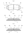
自動車や自動二輪車等の制動に用いられるディスクブレーキパッドは、キャリパ内に収容され、車軸とともに回転するディスクロータの側面を油圧等により挟み込み押さえつけることで摩擦力を発生し、運動エネルギーを熱エネルギーに変換して制動を行う部品であり、図1に示すように、キャリパに取り付けられるバックプレート(裏金)1上に、ディスクロータと摩擦摺動を行う摩擦材2が直接積層された構造、あるいは摩擦材2が接着等をになう中間層3を介して積層された構造となっている。
Disc brake pads used for braking automobiles, motorcycles, etc. are housed in calipers and generate frictional force by holding and pressing the sides of the disc rotor that rotates with the axle with hydraulic pressure to convert kinetic energy into thermal energy. As shown in FIG. 1, a structure in which a
ディスクブレーキパッドは、繊維基材、結合材、有機充填材および無機充填材を含む摩擦材組成物を金型の型孔に充填し、充填された摩擦材組成物を押圧して予備成形し、得られた予備成形体をバックプレート1とともに熱圧成形して一体化した後、必要に応じて熱処理をおこなって結合材の硬化を行い、摩擦材2の上端面2aやチャンファ2bの研削加工、スリット2cの切削加工等の機械加工を経て製造される(特許文献1等)。中間層3を有するディスクブレーキパッドの場合は、中間層を形成する組成物上に摩擦材組成物を積層して充填し、摩擦材組成物と中間層組成物を予備成形することで製造することができる。なお、中間層3を有するディスクブレーキパッドにおいては、摩擦材2を上張材、中間層3を下張材と称すこともある。
The disc brake pad is filled with a friction material composition including a fiber base material, a binder, an organic filler and an inorganic filler in a mold hole of the mold, and the filled friction material composition is pressed to be preformed, After the obtained preform is integrated with the
ディスクブレーキパッドの製造方法においては、上記のように摩擦材2の上端面2aが研削加工等により機械加工されて製造されるが、摩擦材は既に熱硬化しているため除去される部分に関しては、再利用できず廃棄するしかなく、廃棄のためのコストが必要となっている。そこで、廃棄量を削減できれば、その分廃棄のためのコストが低減され、安価にディスクブレーキパッドを製造できることとなる。このことから、本発明は、廃棄量を削減できるディスクブレーキパッドの製造方法を提供することを目的とする。
In the disc brake pad manufacturing method, as described above, the
上記目的を達成するため、本発明者らは、後に機械加工され平坦にされ、摩擦面となる摩擦材上端面に凹凸を形成して、機械加工により摩擦材上端面の凸部のみ除去するようにすれば、摩擦材上端面の凹部の分だけ、廃棄量が削減できると考えた。ただし、単純に予備成形工程と熱圧成形工程において、成形面に凹凸を設けた成形型および熱圧成形型で成形を行うと、成形面に設けた凹部と凸部で圧縮比が異なるため、一様な密度の摩擦材とすることができない。このため本発明者らは、上端面に凹凸を形成しながら比較的一様な密度の摩擦材とする方法について鋭意研究を重ね、本発明を成し遂げた。 In order to achieve the above-mentioned object, the present inventors later machined and flattened to form an unevenness on the friction material upper end surface, which becomes a friction surface, and removes only the convex portion of the friction material upper end surface by machining. In this case, it was considered that the amount of waste can be reduced by the amount of the recess on the upper end surface of the friction material. However, in the preliminary molding step and the hot-pressure molding step, when molding is performed with a molding die having a concavo-convex shape on the molding surface and a hot-pressure molding die, the compression ratio differs between the concave portion and the convex portion provided on the molding surface. A friction material with uniform density cannot be obtained. For this reason, the inventors of the present invention have made extensive studies on a method for producing a friction material having a relatively uniform density while forming irregularities on the upper end surface, thereby accomplishing the present invention.
上記目的を達成する本発明のディスクブレーキパッドの製造方法は、下部金型と、摩擦部材の外周形状を形成する型孔を有する上部金型と、摩擦部材の上端面に形成される凸部を成形する第1成形型と、摩擦部材の上端面に形成される凹部を成形する第2成形型と、からなる金型装置を用いて、下部金型と、上部金型の型孔とにより形成されるキャビティに摩擦部材組成物からなる原材料を充填するとともに、前記摩擦部材の上端面に形成される凹部を成形する第2成形型を下降させて、第2成形型によって形成される凹部の体積分に相当する原材料を予め周囲に流動させ、次いで、摩擦部材の上端面に形成される凸部を成形する第1成形型を降下させるとともに前記第2成形型を降下させて原材料を熱圧成形して予備成形を行い、上端面に凹凸を有する予備成形体を得る予備成形工程と、成形面に前記予備成形体の凹凸の位置に対応する凹凸を有する前記熱圧成形用成形型を用いて熱圧成形して、上端面に凹凸を有する熱圧成形体を得る熱圧成形工程と、前記上端面に凹凸を有する熱圧成形体の上端面を平坦に機械加工する機械加工工程を含むことを特徴とする。 The disc brake pad manufacturing method of the present invention that achieves the above object includes a lower mold, an upper mold having a mold hole that forms the outer peripheral shape of the friction member, and a convex portion formed on the upper end surface of the friction member. Formed by a lower mold and a mold hole of an upper mold using a mold apparatus comprising a first mold for molding and a second mold for molding a recess formed on the upper end surface of the friction member. The cavity is filled with the raw material made of the friction member composition, and the volume of the recess formed by the second mold is lowered by lowering the second mold for forming the recess formed on the upper end surface of the friction member. The raw material corresponding to the minute is preliminarily flowed to the surroundings, and then the first molding die for molding the convex portion formed on the upper end surface of the friction member is lowered and the second molding die is lowered to hot-press the raw material. And then preform it on the top surface A preforming step for obtaining a preform having projections, and hot pressing using the hot-press molding mold having projections and depressions corresponding to the positions of the projections and depressions on the molding surface, and irregularities on the upper end surface. A hot-pressure forming step for obtaining a hot-pressure formed body having a surface and a machining step for machining the upper end surface of the hot-pressure formed body having irregularities on the upper end surface.
上記のディスクブレーキパッドの製造方法においては、前記予備成形工程において、摩擦部材の上端面に形成される凸部を成形する第1成形型を降下させて、前記第2成形型と前記第1成形型の凹凸を所定の位置で一致させた後、前記第1成形型と前記第2成形型を同期して降下させて予備成形をおこなうことが好ましく、また、前記熱圧成形工程において、前記熱圧成形用成形型の成形面に形成された凹凸が、熱圧成形体の圧縮比として等しくなる高さに形成されていることが好ましい。 In the above-described disc brake pad manufacturing method, in the preliminary forming step, the first forming die for forming the convex portion formed on the upper end surface of the friction member is lowered, and the second forming die and the first forming die are lowered. It is preferable that the first mold and the second mold are lowered synchronously after the unevenness of the mold is matched at a predetermined position, and preliminary molding is performed. It is preferable that the unevenness formed on the molding surface of the molding die for pressure molding is formed at a height that is equal as the compression ratio of the hot-press molded body.
本発明のディスクブレーキパッドの製造方法は、摩擦材となる上端面に凹凸を形成するとともに、摩擦材を比較的一様な密度とし、機械加工により摩擦材上端面の凸部のみ除去するようにしたことから、摩擦材の機械加工による廃棄量が削減でき、その分、製造コストを小さくできるという効果を奏する。 In the disc brake pad manufacturing method of the present invention, irregularities are formed on the upper end surface that becomes the friction material, the friction material is made to have a relatively uniform density, and only the convex portions on the upper end surface of the friction material are removed by machining. Therefore, it is possible to reduce the amount of waste due to the machining of the friction material, and the production cost can be reduced correspondingly.
以下に本発明のディスクブレーキパッドの製造方法について説明する。 The method for manufacturing the disc brake pad of the present invention will be described below.
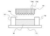
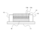
図2に示すように、摩擦部材の下端面を成形する下部金型11と、摩擦部材の外周形状を形成する型孔12aを有する上部金型12と、摩擦部材の上端面に形成される凸部を成形する第1成形型13aと、摩擦部材の上端面に形成される凹部を成形する第2成形型13bからなる金型装置を用意する。すなわち、成形型13は、第1成形型13aと第2成形型13bから構成される。ここで、第1成形型13aの下端面と、第2成形型13bの下端面は滑らかに接続するプロファイルに形成されている。
As shown in FIG. 2, a
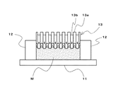
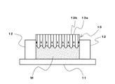
まず、摩擦部材の上端面に形成される凹部を成形する第2成形型13bを降下させて、図3に示すように、摩擦材の凹部に相当する体積分の摩擦材組成物Mを、第2成形型13bの周囲に流動(図中矢印の方向)させる。次いで、図4に示すように、摩擦部材の上端面に形成される凸部を成形する第1成形型13aを降下させて、第1成形型の下端面のプロファイルと、予め降下している第2成形型13bの下端面のプロファイルを一致させ、その後、図5に示すように、第1成形型13aと第2成形型13bを同期して降下させて、摩擦材組成物Mの予備成形を行う。予備成形された予備成形体Pは上端面に凹凸を有するものとなるが、予め摩擦材の凹部に相当する体積分の摩擦材組成物Mを、第2成形型13bの周囲に流動させた後、予備成形を行うため、予備成形体Pの密度分布は比較的均一となる。
First, the second molding die 13b for molding the recess formed on the upper end surface of the friction member is lowered, and as shown in FIG. 2 Flow around the
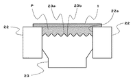
得られた予備成形体Pを用いて熱圧成形を行う。熱圧成形は、図6に示すように、熱圧成形用の金型22の型孔22aと熱成形用成形型23で形成されるキャビティに予備成形体Pを挿入するとともに、バックプレート1を予備成形体P上に積層して配置し、熱圧成形用の金型22と熱成形用成形型23により予備成形体Pを加熱して熱圧成形を行い、熱成形体Tとするとともに、熱圧成形体とバックプレートの一体化を行う。熱成形用成形型23の端面は、凹部23aと凸部23bが形成されており、熱成形用成形型23の凹部23aは予備成形体Pの凸部P2に、熱成形用成形型23の凹部22bは予備成形体Pの凸部P1に、それぞれ対応する位置に形成されている。このとき、熱成形用成形型の凹部23aと凸部23bのプロファイルは、熱圧成形体Tの上端面に形成される凹凸の各部で圧縮比が等しくなるよう形成することが好ましい。
Hot press molding is performed using the obtained preform P. As shown in FIG. 6, the hot pressing is performed by inserting the preform P into a cavity formed by the
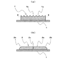
得られた熱成形体Tは、図7(a)に示すように上端面に凹部Taおよび凸部Tbが形成されたものとなっている。この後、図7(a)の点線部より上部にあたる凹部Taおよび凸部Tbを研削等の機械加工により除去して平坦な摩擦面を形成するとともに、チャンファ部および溝部の機械加工を行い、図7(b)に示すディスクブレーキパッドとする。摩擦面の機械加工においては、摩擦材の凸部Taの分は廃棄することとなるが、摩擦材の凹部Tbの分だけ廃棄量が削減でき、その分製造コストを低減することができる。 As shown in FIG. 7A, the obtained thermoformed body T has a concave portion Ta and a convex portion Tb formed on the upper end surface. Thereafter, the concave portion Ta and the convex portion Tb, which are above the dotted line portion of FIG. 7A, are removed by machining such as grinding to form a flat friction surface, and the chamfer portion and the groove portion are machined. The disc brake pad shown in FIG. In the machining of the friction surface, the convex portion Ta of the friction material is discarded, but the discard amount can be reduced by the concave portion Tb of the friction material, and the manufacturing cost can be reduced correspondingly.
上記の形態は、凹凸を波形として形成した例であるが、矩形、台形等としてもよい。また、上記の形態は、成形型13および熱圧成形用成形型23の凹凸の間隔を等間隔に配置した例であるが、成形型13および熱圧成形用成形型23の凹凸の間隔を不等間隔に配置することもできる。また、凹凸は一方向に連続した形状とすることもできるし、斑状に形成することもできる。 The above form is an example in which the unevenness is formed as a waveform, but may be a rectangle, a trapezoid or the like. Further, the above embodiment is an example in which the concave and convex intervals of the molding die 13 and the hot-pressure molding die 23 are arranged at equal intervals. It can also be arranged at equal intervals. Further, the unevenness can be formed in a continuous shape in one direction or can be formed in a patch shape.
以上は、バックプレート上に直接摩擦材を積層したディスクブレーキパッドの製造方法の例であるが、充填工程において、下部金型10と、上部金型11の型孔11aにより形成されるキャビティに中間層を形成する中間層組成物を充填した後、充填された中間層組成物の上に摩擦材組成物を積層して充填し、後の工程は上記と同様にすることで、バックプレート上に、摩擦材が中間層を介して積層されたディスクブレーキパッドを製造することができる。
The above is an example of a method for manufacturing a disc brake pad in which a friction material is directly laminated on a back plate. In the filling process, an intermediate is provided between the lower mold 10 and the cavity formed by the mold hole 11a of the
なお、摩擦材の組成としては、従来の摩擦材組成物をそのまま用いることができる。すなわち、摩擦材組成物として、繊維基材、結合剤、有機充填材および無機充填材を含む摩擦材組成物を用いることができる。基材繊維としては、ガラス繊維、炭素繊維、金属繊維、セラミック繊維、ロックウール、アラミド繊維、アクリル繊維等を用いることができる。結合材としては、熱硬化性樹脂であって、フェノール骨格を有する、熱劣化しても炭素として残りにくい樹脂が好ましく、フェノール樹脂やアクリルや各種エラストマで変性したフェノール樹脂等を用いることができる。有機充填材としては、カシューダスト、ゴムダスト等の有機粉末を用いることができる。無機充填材としては、アルミナやジルコニア等の無機粉末粒子、黒鉛、硫化アンチモン、硫化錫等の潤滑剤、銅、アルミニウム、亜鉛等の金属粉末粒子を用いることができる。 In addition, as a composition of a friction material, the conventional friction material composition can be used as it is. That is, as the friction material composition, a friction material composition including a fiber base material, a binder, an organic filler, and an inorganic filler can be used. As the base fiber, glass fiber, carbon fiber, metal fiber, ceramic fiber, rock wool, aramid fiber, acrylic fiber, or the like can be used. The binder is preferably a thermosetting resin that has a phenol skeleton and is difficult to remain as carbon even when thermally deteriorated. For example, a phenol resin or a phenol resin modified with acrylic or various elastomers can be used. As the organic filler, organic powders such as cashew dust and rubber dust can be used. As the inorganic filler, inorganic powder particles such as alumina and zirconia, lubricants such as graphite, antimony sulfide and tin sulfide, and metal powder particles such as copper, aluminum and zinc can be used.
また、上記の予備成形工程、熱圧成形工程および機械加工工程の他、従来から行われている他の工程を必要に応じ追加してもよい。すなわち本発明のディスクブレーキパッドの製造方法においては、樹脂の硬化を促進する熱処理工程を設けてもよく、摩擦材の表面をスコーチ処理するスコーチ処理工程を設けてもよく、ディスクブレーキパッドの塗装工程を追加してもよい。 Moreover, you may add the other process conventionally performed other than said preforming process, a hot-pressure forming process, and a machining process as needed. That is, in the disc brake pad manufacturing method of the present invention, a heat treatment step for promoting the curing of the resin may be provided, a scorch treatment step for scorching the surface of the friction material may be provided, and a disc brake pad coating step. May be added.
本発明のディスクブレーキパッドは、機械加工により廃棄される素材の量を低減でき、その分廃棄コストが抑制できるものであり、自動車や自動二輪車等の制動に用いられるディスクブレーキパッドの製造方法として好適なものである。 The disc brake pad of the present invention can reduce the amount of material discarded by machining, and can accordingly reduce the disposal cost, and is suitable as a method for manufacturing a disc brake pad used for braking an automobile, a motorcycle, etc. Is something.
1…バックプレート、2…摩擦材、2a…摩擦材の上端面、2b…摩擦材のチャンファ、2c…摩擦材のスリット、3…中間層、
11…下部金型、12…上部金型、12a…上部金型の型孔、13…成形型、13a…第1成形型、13b…第2成形型、
22…熱圧成形用の金型、22a…熱圧成形用の金型の型孔、23…熱成形用成形型、23a…熱成形用成形型の凹部、23b…熱成形用成形型の凸部、
P…予備成形体、Pa…予備成形体の凹部、Pb…予備成形体の凸部、
T…熱成形体、Ta…熱成形体の凹部、Tb…熱成形体の凸部
DESCRIPTION OF
DESCRIPTION OF
DESCRIPTION OF
P ... preformed body, Pa ... recessed part of preformed body, Pb ... convex part of preformed body,
T: Thermoformed body, Ta: Concavity of thermoformed body, Tb: Convex portion of thermoformed body
Claims (3)
下部金型と、上部金型の型孔とにより形成されるキャビティに摩擦部材組成物からなる原材料を充填するとともに、
前記摩擦部材の上端面に形成される凹部を成形する第2成形型を下降させて、第2成形型によって形成される凹部の体積分に相当する原材料を予め周囲に流動させ、
次いで、摩擦部材の上端面に形成される凸部を成形する第1成形型を降下させるとともに前記第2成形型を降下させて原材料を熱圧成形して予備成形を行い、上端面に凹凸を有する予備成形体を得る予備成形工程と、
成形面に前記予備成形体の凹凸の位置に対応する凹凸を有する熱圧成形用成形型を用いて熱圧成形して、上端面に凹凸を有する熱圧成形体を得る熱圧成形工程と、
前記上端面に凹凸を有する熱圧成形体の上端面を平坦に機械加工する機械加工工程を含むことを特徴とするディスクブレーキパッドの製造方法。 A lower mold, an upper mold having a mold hole that forms the outer peripheral shape of the friction member, a first mold for molding a convex portion formed on the upper end surface of the friction member, and an upper end surface of the friction member. A mold device comprising a second mold for molding the recess
Filling the cavity formed by the lower mold and the mold hole of the upper mold with the raw material made of the friction member composition,
Lowering the second mold for molding the recess formed on the upper end surface of the friction member, and flowing the raw material corresponding to the volume of the recess formed by the second mold in advance to the surroundings,
Next, the first mold for forming the convex portion formed on the upper end surface of the friction member is lowered and the second mold is lowered to perform the hot molding of the raw material to perform the preforming, and the upper end surface is uneven. A preforming step to obtain a preform with
Hot pressing using a hot-pressure forming mold having irregularities corresponding to the positions of the irregularities of the preform on the molding surface, to obtain a hot-pressure molded article having irregularities on the upper end surface; and
A method for manufacturing a disc brake pad, comprising: a machining step of machining a top end surface of a hot-pressed body having irregularities on the top end surface.
Priority Applications (1)
| Application Number | Priority Date | Filing Date | Title |
|---|---|---|---|
| JP2016082944A JP6765211B2 (en) | 2016-04-18 | 2016-04-18 | How to manufacture disc brake pads |
Applications Claiming Priority (1)
| Application Number | Priority Date | Filing Date | Title |
|---|---|---|---|
| JP2016082944A JP6765211B2 (en) | 2016-04-18 | 2016-04-18 | How to manufacture disc brake pads |
Publications (2)
| Publication Number | Publication Date |
|---|---|
| JP2017194082A true JP2017194082A (en) | 2017-10-26 |
| JP6765211B2 JP6765211B2 (en) | 2020-10-07 |
Family
ID=60155874
Family Applications (1)
| Application Number | Title | Priority Date | Filing Date |
|---|---|---|---|
| JP2016082944A Active JP6765211B2 (en) | 2016-04-18 | 2016-04-18 | How to manufacture disc brake pads |
Country Status (1)
| Country | Link |
|---|---|
| JP (1) | JP6765211B2 (en) |
Cited By (1)
| Publication number | Priority date | Publication date | Assignee | Title |
|---|---|---|---|---|
| JP2019157925A (en) * | 2018-03-08 | 2019-09-19 | 日本ブレーキ工業株式会社 | Process of manufacture of disc brake pad, disc brake pad and die for friction member of disc brake pad |
-
2016
- 2016-04-18 JP JP2016082944A patent/JP6765211B2/en active Active
Cited By (1)
| Publication number | Priority date | Publication date | Assignee | Title |
|---|---|---|---|---|
| JP2019157925A (en) * | 2018-03-08 | 2019-09-19 | 日本ブレーキ工業株式会社 | Process of manufacture of disc brake pad, disc brake pad and die for friction member of disc brake pad |
Also Published As
| Publication number | Publication date |
|---|---|
| JP6765211B2 (en) | 2020-10-07 |
Similar Documents
| Publication | Publication Date | Title |
|---|---|---|
| JP6171031B2 (en) | Carbon ceramic brake disc and method of manufacturing the same | |
| CN101549566B (en) | Friction lining | |
| CN101238305A (en) | Friction discs and their different manufacturing methods | |
| KR101984193B1 (en) | Improved friction material tooling | |
| JP6765211B2 (en) | How to manufacture disc brake pads | |
| JP5531600B2 (en) | Manufacturing method of disc brake pad | |
| JP4766925B2 (en) | Friction material manufacturing method | |
| JP2012211676A (en) | Brake pad | |
| JP2019157925A (en) | Process of manufacture of disc brake pad, disc brake pad and die for friction member of disc brake pad | |
| JP2013057337A (en) | Brake pad, and method of manufacturing the same | |
| JP5393435B2 (en) | Disc brake pad | |
| JP4560725B2 (en) | Press molding machine, press molding method, and disk brake pad obtained by press molding machine and press molding method | |
| JP6763688B2 (en) | Disc brake pad molding method | |
| JP6584800B2 (en) | Manufacturing method of disc brake pad | |
| KR101216144B1 (en) | Carbon-ceramic brake disc and method for manufacturing the same | |
| KR101258828B1 (en) | Carbon-ceramic brake disk and method for fabricating the same, and multifunctional core for being used in the same | |
| CN100389274C (en) | Preparation process for disk type brake lining and dedicated apparatus therefor | |
| JP5969327B2 (en) | Insulating mold manufacturing method | |
| JPH07167173A (en) | Brake pad manufacturing method | |
| CN102472329A (en) | Method for producing a friction lining | |
| JP4439362B2 (en) | Friction material manufacturing method and apparatus | |
| JP2904244B2 (en) | Method of manufacturing friction pad for disc brake | |
| CN207621205U (en) | Two-in-one clutch surface | |
| CN105722655A (en) | Friction ring and method for producing a friction ring | |
| TWI613020B (en) | Brake-making continuous hot pressing sintering device |
Legal Events
| Date | Code | Title | Description |
|---|---|---|---|
| RD02 | Notification of acceptance of power of attorney |
Free format text: JAPANESE INTERMEDIATE CODE: A7422 Effective date: 20180808 |
|
| RD04 | Notification of resignation of power of attorney |
Free format text: JAPANESE INTERMEDIATE CODE: A7424 Effective date: 20180808 |
|
| A621 | Written request for application examination |
Free format text: JAPANESE INTERMEDIATE CODE: A621 Effective date: 20190322 |
|
| A977 | Report on retrieval |
Free format text: JAPANESE INTERMEDIATE CODE: A971007 Effective date: 20200319 |
|
| A131 | Notification of reasons for refusal |
Free format text: JAPANESE INTERMEDIATE CODE: A131 Effective date: 20200409 |
|
| A521 | Request for written amendment filed |
Free format text: JAPANESE INTERMEDIATE CODE: A523 Effective date: 20200604 |
|
| TRDD | Decision of grant or rejection written | ||
| A01 | Written decision to grant a patent or to grant a registration (utility model) |
Free format text: JAPANESE INTERMEDIATE CODE: A01 Effective date: 20200910 |
|
| A61 | First payment of annual fees (during grant procedure) |
Free format text: JAPANESE INTERMEDIATE CODE: A61 Effective date: 20200915 |
|
| R150 | Certificate of patent or registration of utility model |
Ref document number: 6765211 Country of ref document: JP Free format text: JAPANESE INTERMEDIATE CODE: R150 |
|
| S533 | Written request for registration of change of name |
Free format text: JAPANESE INTERMEDIATE CODE: R313533 |
|
| R350 | Written notification of registration of transfer |
Free format text: JAPANESE INTERMEDIATE CODE: R350 |