JP2017194465A - Monitoring device - Google Patents

Monitoring device Download PDF

Info

Publication number
JP2017194465A
JP2017194465A JP2017081904A JP2017081904A JP2017194465A JP 2017194465 A JP2017194465 A JP 2017194465A JP 2017081904 A JP2017081904 A JP 2017081904A JP 2017081904 A JP2017081904 A JP 2017081904A JP 2017194465 A JP2017194465 A JP 2017194465A
Authority
JP
Japan
Prior art keywords
phase
voltage
current
ground line
transformer
Prior art date
Legal status (The legal status is an assumption and is not a legal conclusion. Google has not performed a legal analysis and makes no representation as to the accuracy of the status listed.)
Pending
Application number
JP2017081904A
Other languages
Japanese (ja)
Inventor
恭二 大西
Kyoji Onishi
恭二 大西
文雄 岩崎
Fumio Iwasaki
文雄 岩崎
桑原 延行
Nobuyuki Kuwabara
延行 桑原
Current Assignee (The listed assignees may be inaccurate. Google has not performed a legal analysis and makes no representation or warranty as to the accuracy of the list.)
MULTI KEISOKUKI KK
Original Assignee
MULTI KEISOKUKI KK
Priority date (The priority date is an assumption and is not a legal conclusion. Google has not performed a legal analysis and makes no representation as to the accuracy of the date listed.)
Filing date
Publication date
Application filed by MULTI KEISOKUKI KK filed Critical MULTI KEISOKUKI KK
Publication of JP2017194465A publication Critical patent/JP2017194465A/en
Pending legal-status Critical Current

Links

Images

Landscapes

  • Testing Of Short-Circuits, Discontinuities, Leakage, Or Incorrect Line Connections (AREA)

Abstract

PROBLEM TO BE SOLVED: To provide a monitoring device for monitoring an electrical state of an electric circuit.SOLUTION: A monitoring device 1 includes: a first current detection part 55 for detecting a B kind ground wire current of an electric circuit at a low-voltage side of a three-phase transformer 2 or a single-phase transformer 3 in which a high-voltage side is connected to a three-phase electric circuit; a second current detection part 56 for detecting a second ground line current flowing to a high-voltage cable ground line of either electric circuit of the three-phase electric circuit; and a monitoring part 57. The monitoring part 57 synchronously detects the B kind ground wire current by a phase of the second ground line current to measure a resistive leakage current Ior at a low-voltage side of the three-phase transformer 2 or the single-phase transformer 3, and monitors an electrical state of an electric circuit at a low-voltage side of the three-phase transformer 2 or the single-phase transformer 3 according to a measurement result of the resistive leakage current Ior. The monitoring result is displayed on a display part 58.SELECTED DRAWING: Figure 16

Description

この発明は、電路の電気的状態を監視する監視装置に関する。監視対象となる電路を、以下、「被監視電路」という。なお電気的状態は、例えば被監視電路の絶縁状態、電力、潮流、漏電方向、漏れ電流等である。   The present invention relates to a monitoring device that monitors the electrical state of an electric circuit. The electric circuit to be monitored is hereinafter referred to as “monitored electric circuit”. The electrical state is, for example, the insulation state of the monitored circuit, power, power flow, leakage direction, leakage current, and the like.

被監視電路の交流電圧の電圧位相及び電流を測定することで、被監視電路の絶縁状態、電力、潮流、漏電方向等の電気的状態を監視する監視装置がある。被監視電路の電流の測定は、電流センサを用いて非接触で行うことができる。被監視電路の電圧位相の測定は、充電部に接触して行う。充電部に接触して電圧位相を測定する方法には、被覆電線の上方に開口を設けて直接接触して測定する方法、被覆電線の上から静電容量を利用して測定する方法等がある。特許文献1は、測定プローブを電線に正確に当接した状態で電圧測定を行うことができる被接触電圧測定器を開示する。高圧の電圧位相を測定する場合、変圧器、コンデンサ等で絶縁して変換する方法がある。   There is a monitoring device that monitors the electrical state such as the insulation state, power, power flow, and leakage direction of the monitored circuit by measuring the voltage phase and current of the AC voltage of the monitored circuit. The current in the monitored circuit can be measured in a non-contact manner using a current sensor. The voltage phase of the monitored circuit is measured in contact with the charging unit. Examples of the method of measuring the voltage phase by contacting the charged part include a method in which an opening is provided above the covered electric wire and the direct contact is made, and a method in which the capacitance is measured from above the covered electric wire. . Patent Document 1 discloses a contacted voltage measuring device that can perform voltage measurement in a state in which a measurement probe is accurately in contact with an electric wire. When measuring the voltage phase of high voltage, there is a method of converting by insulating with a transformer, a capacitor or the like.

特開2014−163670号公報JP 2014-163670 A

充電部に直接接触して電圧位相を測定する場合、安全のために停電する必要がある。また、被覆電線に開口を設けて直接接触して測定する場合、電線の種類や大きさによって電線の静電容量が異なり、測定結果にその影響が大きく作用する。この場合、静電容量の相違を補正する必要があるが、そのための補正装置が非常に複雑であり、コストも高くなる。また、高圧の電圧位相の測定には、高圧側との絶縁のために変圧器やコンデンサが必要になり、構成が複雑になりやすい。   When measuring the voltage phase in direct contact with the live part, a power outage is necessary for safety. Moreover, when measuring by providing an opening in a covered electric wire and making direct contact, the electrostatic capacitance of the electric wire varies depending on the type and size of the electric wire, and the effect of the measurement greatly affects. In this case, it is necessary to correct the difference in capacitance, but the correction device for that purpose is very complicated and the cost is increased. In addition, the measurement of the high voltage phase requires a transformer and a capacitor for insulation from the high voltage side, and the configuration tends to be complicated.

本発明は、上記の問題に鑑み、被監視電路の電気的状態を監視する監視装置を提供することを主たる課題とする。   This invention makes it a main subject to provide the monitoring apparatus which monitors the electrical state of a to-be-monitored electric circuit in view of said problem.

上記課題を解決するための本発明の監視装置は、高圧側が3相電路に接続された変圧器の低圧側の電路の第1接地線電流を検出する第1検出手段と、前記3相電路のいずれかの電路の高圧ケーブル接地線に流れる第2接地線電流を検出する第2検出手段と、前記第2接地線電流の位相により前記第1接地線電流を同期検波することで、前記変圧器の前記低圧側の電気的状態を監視する監視手段と、を備えることを特徴とする。   The monitoring device of the present invention for solving the above-described problem includes a first detection means for detecting a first ground line current of a low-voltage side electric circuit of a transformer whose high-voltage side is connected to a three-phase electric circuit, A second detecting means for detecting a second ground line current flowing in a high-voltage cable ground line of any one of the electric lines; and the first ground line current is synchronously detected by the phase of the second ground line current, thereby the transformer. Monitoring means for monitoring the electrical state of the low-pressure side.

本発明によれば、被監視線路から交流電圧を取り込むことなく、被監視線路の電気的状態を監視することが可能となる。   According to the present invention, it is possible to monitor the electrical state of the monitored line without taking in an AC voltage from the monitored line.

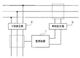
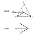
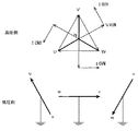
監視システムの構成図。The block diagram of a monitoring system. 3相変圧器及び単相変圧器の説明図。Explanatory drawing of a three-phase transformer and a single phase transformer. 単相変圧器の結線と3相変圧器の結線との関係を示す図。The figure which shows the relationship between the connection of a single phase transformer, and the connection of a three-phase transformer. 単相変圧器の高圧側と低圧側との電圧位相の関係の説明図。Explanatory drawing of the relationship of the voltage phase of the high voltage | pressure side and low voltage | pressure side of a single phase transformer. スター/デルタ結線の3相変圧器の高圧側と低圧側との電圧位相の説明図。Explanatory drawing of the voltage phase of the high voltage | pressure side and low voltage | pressure side of a three-phase transformer of a star / delta connection. スター/スター結線の3相変圧器の高圧側と低圧側との電圧位相の説明図。Explanatory drawing of the voltage phase of the high voltage | pressure side and low voltage | pressure side of a three-phase transformer of a star / star connection. 絶縁監視装置の外観図。The external view of an insulation monitoring apparatus. 絶縁監視装置のハードウェア構成図。The hardware block diagram of an insulation monitoring apparatus. 絶縁監視装置の機能ブロック図。The functional block diagram of an insulation monitoring apparatus. 電力測定器の外観図。The external view of an electric power measuring device. 電力測定器の機能ブロック図。The functional block diagram of an electric power measuring device. 潮流方向測定器の外観図。External view of a tidal direction measuring instrument. 潮流方向測定器の機能ブロック図。Functional block diagram of the tidal current direction measuring instrument. 漏電方向測定器の外観図。External view of a leakage direction measuring instrument. 漏電方向測定器の機能ブロック図。Functional block diagram of a leakage direction measuring instrument. (a)、(b)は、被監視線路の交流電流と、3相電路の接地線を流れる接地線電流とにより、被監視線路の電気的状態を監視する監視システムの構成図。(A), (b) is a block diagram of the monitoring system which monitors the electrical state of a to-be-monitored track | line by the alternating current of a to-be-monitored track | line and the ground wire current which flows through the ground wire of a three-phase circuit. 位相の説明図。Explanatory drawing of a phase. 位相の説明図。Explanatory drawing of a phase.

以下、本発明の実施の形態を図面を用いて詳細に説明する。   Hereinafter, embodiments of the present invention will be described in detail with reference to the drawings.

(監視システム)
図1は、被監視電路の絶縁状態、電力、潮流、漏電方向等の電気的状態を監視する監視システムの構成図である。監視装置1は、3相変圧器2及び制御電源となる単相変圧器3が接続される。3相変圧器2は、高圧側が3相電路に接続され、低圧側が監視装置1に接続される動力回路である。本実施形態では、3相変圧器2の低圧側を監視装置1の監視対象となる被監視電路として説明するが、3相変圧器2の高圧側を被監視電路としてもよい。単相変圧器3は、高圧側が3相電路のいずれか2相に接続され、低圧側が監視装置1に交流電圧を供給する電灯回路である。
(Monitoring system)
FIG. 1 is a configuration diagram of a monitoring system that monitors an electrical state such as an insulation state, electric power, power flow, and direction of leakage of a monitored electric circuit. The monitoring device 1 is connected to a three-phase transformer 2 and a single-phase transformer 3 serving as a control power source. The three-phase transformer 2 is a power circuit in which the high voltage side is connected to the three-phase electric circuit and the low voltage side is connected to the monitoring device 1. In the present embodiment, the low voltage side of the three-phase transformer 2 will be described as a monitored electric circuit to be monitored by the monitoring device 1, but the high voltage side of the three-phase transformer 2 may be a monitored electric circuit. The single-phase transformer 3 is a lamp circuit in which a high voltage side is connected to any two phases of a three-phase electric circuit, and a low voltage side supplies an AC voltage to the monitoring device 1.

従来のこの種の監視システムでは、監視装置1が、被監視電路の交流電圧の電圧位相と電流とに基づいて電気的状態を監視することになる。そのために監視装置1には、被監視電路から交流電圧及び電流が入力される。
これに対して本実施形態の監視システムでは、監視装置1に被監視電路から電流が入力されるが、交流電圧は入力されない。本実施形態の監視装置1は、単相変圧器3の高圧側の2相と、3相変圧器2の結線の種類とに基づいて、被監視電路の交流電圧の電圧位相を測定する。そのために監視装置1は、被監視電路の交流電圧の入力を必要としない。単相変圧器3の高圧側の2相と、3相変圧器2の結線の種類とに基づいて、被監視電路の交流電圧の電圧位相を測定する方法について説明する。
In this type of conventional monitoring system, the monitoring device 1 monitors the electrical state based on the voltage phase and current of the AC voltage of the monitored circuit. For this purpose, the monitoring device 1 receives AC voltage and current from the monitored electric circuit.
On the other hand, in the monitoring system of the present embodiment, a current is input to the monitoring device 1 from the monitored electric circuit, but no AC voltage is input. The monitoring device 1 of the present embodiment measures the voltage phase of the AC voltage of the monitored circuit based on the two phases on the high voltage side of the single-phase transformer 3 and the type of connection of the three-phase transformer 2. Therefore, the monitoring device 1 does not need to input an AC voltage of the monitored circuit. A method for measuring the voltage phase of the AC voltage of the monitored circuit based on the two phases on the high voltage side of the single-phase transformer 3 and the type of connection of the three-phase transformer 2 will be described.

(電圧位相)
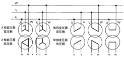
図2は、3相変圧器2及び単相変圧器3の説明図である。3相変圧器2及び単相変圧器3は、高圧側が3相電路(U相、V相、W相)に接続される。3相電路には、例えば6.6[kV]の高圧が印加されており、3相変圧器2及び単相変圧器3の高圧側に、6.6[kV]の交流電圧が印加される。3相変圧器2及び単相変圧器3は、高圧側の交流電圧を低圧、例えば200[V]や100[V]の交流電圧に変換して出力する。
(Voltage phase)
FIG. 2 is an explanatory diagram of the three-phase transformer 2 and the single-phase transformer 3. The high-voltage side of the three-phase transformer 2 and the single-phase transformer 3 is connected to a three-phase electric circuit (U phase, V phase, W phase). For example, a high voltage of 6.6 [kV] is applied to the three-phase circuit, and an alternating voltage of 6.6 [kV] is applied to the high-voltage side of the three-phase transformer 2 and the single-phase transformer 3. . The three-phase transformer 2 and the single-phase transformer 3 convert the AC voltage on the high voltage side into a low voltage, for example, an AC voltage of 200 [V] or 100 [V], and output it.

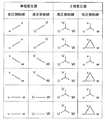
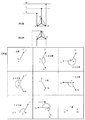
3相変圧器2の高圧側の結線と低圧側の結線とは、スター/デルタ結線やスター/スター結線のように規格化されている。単相変圧器3は、高圧側の3相のうちの2相を接続相として電圧変換を行う。2相の組み合わせは、U−V相、V−W相、W−U相の3通りである。図3は、単相変圧器3の結線と3相変圧器2の結線との関係を示す図である。図3に示すように、単相変圧器3の接続相と、3相変圧器2の結線との組み合わせは6種類になる。   The high-voltage side connection and the low-voltage side connection of the three-phase transformer 2 are standardized like a star / delta connection or a star / star connection. The single-phase transformer 3 performs voltage conversion using two phases of the three phases on the high voltage side as connection phases. There are three combinations of two phases: U-V phase, V-W phase, and W-U phase. FIG. 3 is a diagram illustrating the relationship between the connection of the single-phase transformer 3 and the connection of the three-phase transformer 2. As shown in FIG. 3, there are six combinations of the connection phase of the single-phase transformer 3 and the connection of the three-phase transformer 2.

図4は、単相変圧器3の高圧側と低圧側との電圧位相の関係の説明図である。単相変圧器3では、高圧側と低圧側とで、同じ接続相(U−V線間とu−v線間、V−W線間とv−w線間、W−U線間とw−u線間)の電圧位相が同相になる。つまり単相変圧器3の高圧側と低圧側との位相差は、接続相にかかわらず0度である。   FIG. 4 is an explanatory diagram of the voltage phase relationship between the high voltage side and the low voltage side of the single-phase transformer 3. In the single-phase transformer 3, the same connection phase (between the U and V lines and between the uv lines, between the V and W lines, between the v and w lines, between the W and U lines, and between the high voltage side and the low voltage side. The voltage phase (between -u lines) is in phase. That is, the phase difference between the high voltage side and the low voltage side of the single-phase transformer 3 is 0 degree regardless of the connection phase.

図5は、スター/デルタ結線の3相変圧器2の高圧側と低圧側との電圧位相の説明図である。図5に示すように、例えば高圧側のU相からV相を見た交流電圧(U−V線間の電圧)に対して、低圧側のu相からv相を見た交流電圧(u−v線間の電圧)の位相が30度遅れる。高圧側のU相からV相を見た交流電圧(U−V線間の電圧)に対して、低圧側のv相からw相を見た交流電圧(v−w線間の電圧)の位相が150度遅れる。高圧側のU相からV相を見た交流電圧(U−V線間の電圧)に対して、低圧側のw相からu相を見た交流電圧(w−u線間の電圧)の位相が270度遅れる。
高圧側の接続相が他の場合(V相からW相を見た交流電圧(V−W線間の電圧)、W相からU相を見た交流電圧(W−U線間の電圧))についても、位相差は同様である。
このように3相変圧器2がスター/デルタ結線である場合、3相変圧器2の高圧側と低圧側との位相差は、30度、150度、270度のいずれかになる。
FIG. 5 is an explanatory diagram of the voltage phase of the high-voltage side and the low-voltage side of the star / delta-connected three-phase transformer 2. As shown in FIG. 5, for example, an AC voltage (u− that looks at the v phase from the u phase on the low voltage side) is an AC voltage (u−V line voltage) that looks at the V phase from the U phase on the high voltage side. The phase of the voltage between the v lines is delayed by 30 degrees. Phase of AC voltage (voltage between v-w lines) viewed from low-phase v-phase to w-phase with respect to AC voltage (voltage between U-V lines) viewed from high-phase U-phase to V-phase Is delayed by 150 degrees. Phase of AC voltage (voltage between w-u lines) seen from low-phase w phase to u-phase with respect to AC voltage (voltage between U-V lines) seen from U phase on high-voltage side Is delayed by 270 degrees.
When the connecting phase on the high voltage side is other (AC voltage looking from the V phase to the W phase (voltage between the V and W lines), AC voltage looking from the W phase to the U phase (the voltage between the W and U lines)) The phase difference is also the same.
Thus, when the three-phase transformer 2 has a star / delta connection, the phase difference between the high-voltage side and the low-voltage side of the three-phase transformer 2 is either 30 degrees, 150 degrees, or 270 degrees.

図6は、スター/スター結線の3相変圧器2の高圧側と低圧側との電圧位相の説明図である。図6に示すように、例えば高圧側のU相からV相を見た交流電圧(U−V線間の電圧)の位相は、低圧側のu相からv相を見た交流電圧(u−v線間の電圧)と同じ位相であり、位相差は0度である。高圧側のU相からV相を見た交流電圧(U−V線間の電圧)に対して、低圧側のv相からw相を見た交流電圧(v−w線間の電圧)の位相が120度遅れる。高圧側のU相からV相を見た交流電圧(U−V線間の電圧)に対して、低圧側のw相からu相を見た交流電圧(w−u線間の電圧)の位相が240度遅れる。
高圧側の接続相が他の場合(V相からW相を見た交流電圧(V−W線間の電圧)、W相からU相を見た交流電圧(W−U線間の電圧))についても、位相差は同様である。
このように3相変圧器2がスター/スター結線である場合、3相変圧器2の高圧側と低圧側との位相差は、0度、120度、240度のいずれかになる。
FIG. 6 is an explanatory diagram of the voltage phase between the high voltage side and the low voltage side of the star / star connection three-phase transformer 2. As shown in FIG. 6, for example, the phase of the AC voltage (voltage between U-V lines) when the V phase is viewed from the U phase on the high voltage side is the AC voltage (u−) when the v phase is viewed from the u phase on the low voltage side. and the phase difference is 0 degree. Phase of AC voltage (voltage between v-w lines) viewed from low-phase v-phase to w-phase with respect to AC voltage (voltage between U-V lines) viewed from high-phase U-phase to V-phase Is delayed 120 degrees. Phase of AC voltage (voltage between w-u lines) seen from low-phase w phase to u-phase with respect to AC voltage (voltage between U-V lines) seen from U phase on high-voltage side Is delayed by 240 degrees.
When the connecting phase on the high voltage side is other (AC voltage looking from the V phase to the W phase (voltage between the V and W lines), AC voltage looking from the W phase to the U phase (the voltage between the W and U lines)) The phase difference is also the same.
Thus, when the three-phase transformer 2 is a star / star connection, the phase difference between the high-voltage side and the low-voltage side of the three-phase transformer 2 is 0 degree, 120 degrees, or 240 degrees.

単相変圧器3の高圧側と低圧側とが同相であり、かつ単相変圧器3と3相変圧器2の高圧側が同じ3相電路に接続される。そのために、3相変圧器2の高圧側と低圧側との交流電圧の位相差は、単相変圧器3の低圧側の交流電圧の電圧位相と被監視電路の交流電圧の位相差と同じになる。監視装置1は、単相変圧器3の低圧側から入力される交流電圧を、3相変圧器2の結線の種類と単相変圧器3の高圧側の接続相とにより得らる3相変圧器2の高圧側と低圧側との交流電圧の位相差により位相変換する。監視装置1は、この位相変換した交流電圧により、被監視電路の交流電流の電圧位相を測定することが可能になる。単相変圧器3の高圧側の接続相は、変電室やキュービクルで実際に単相変圧器3の高圧側の接続を確認することで判明する。   The high-voltage side and the low-voltage side of the single-phase transformer 3 are in phase, and the single-phase transformer 3 and the high-voltage side of the three-phase transformer 2 are connected to the same three-phase circuit. Therefore, the phase difference of the AC voltage between the high voltage side and the low voltage side of the three-phase transformer 2 is the same as the voltage phase of the AC voltage of the low voltage side of the single phase transformer 3 and the AC voltage of the monitored circuit. Become. The monitoring device 1 is a three-phase transformer that obtains an AC voltage input from the low-voltage side of the single-phase transformer 3 according to the type of connection of the three-phase transformer 2 and the connection phase on the high-voltage side of the single-phase transformer 3. Phase conversion is performed by the phase difference of the AC voltage between the high voltage side and the low voltage side of the container 2. The monitoring device 1 can measure the voltage phase of the AC current in the monitored circuit by using the AC voltage subjected to the phase conversion. The connection phase on the high-voltage side of the single-phase transformer 3 can be determined by actually checking the connection on the high-voltage side of the single-phase transformer 3 in a substation or cubicle.

(監視処理)
監視装置1は、3相変圧器2がスター/デルタ結線である場合に、単相変圧器3の高圧側が接続される2相に応じて、制御電源から入力される交流電圧の位相を30度、150度、270度のいずれかに変換することになる。また監視装置1は、3相変圧器2がスター/スター結線である場合に、単相変圧器3の高圧側が接続される2相に応じて、制御電源から入力される交流電圧の位相を0度、120度、240度のいずれかに変換することになる。監視装置1は、制御電源から入力される交流電圧の電圧位相を位相変換し、位相変換後の交流電圧の電圧位相と被監視電路を流れる電流とにより、被監視電路の電気的状態を監視する。そのために監視装置1は、被監視電路からの交流電圧の入力を必要としない。以下に、監視装置1の具体例を説明する。
(Monitoring process)
When the three-phase transformer 2 has a star / delta connection, the monitoring device 1 sets the phase of the AC voltage input from the control power supply to 30 degrees according to the two phases to which the high-voltage side of the single-phase transformer 3 is connected. , 150 degrees, or 270 degrees. In addition, when the three-phase transformer 2 has a star / star connection, the monitoring device 1 sets the phase of the AC voltage input from the control power supply to 0 according to the two phases to which the high-voltage side of the single-phase transformer 3 is connected. It will be converted to any one of degrees, 120 degrees, and 240 degrees. The monitoring device 1 performs phase conversion on the voltage phase of the AC voltage input from the control power supply, and monitors the electrical state of the monitored circuit by using the voltage phase of the AC voltage after phase conversion and the current flowing through the monitored circuit. . Therefore, the monitoring apparatus 1 does not require input of an AC voltage from the monitored electric circuit. Below, the specific example of the monitoring apparatus 1 is demonstrated.

(絶縁監視装置)
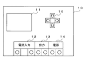
図7は、上記のような監視システムを応用した、被監視電路の絶縁状態を抵抗分漏れ電流Iorにより監視する絶縁監視装置の外観図である。絶縁監視装置10は、表示部11、電流入力部12、出力部13、制御電源入力部14、及び設定部15を備える。この絶縁監視装置10は、被監視電路である3相変圧器2の低圧側の抵抗分漏れ電流Iorを測定し、測定結果に応じて被監視電路の絶縁状態を監視する。表示部11は、電圧位相の位相変換量設定時の設定画面や、絶縁状態の監視結果の表示を行う。電流入力部12は、被監視電路に流れる電流が入力される。出力部13は、外部装置に監視結果を出力する。制御電源入力部14は、制御電源から交流電圧が入力される。制御電源は、高圧側が3相電路のいずれか2相に接続される単相変圧器3であり、低圧側から、例えばAC100[V]の交流電圧を制御電源入力部14に入力する。設定部15は、制御電源から入力される交流電圧の位相を変換するための位相変換量を入力する入力装置である。
(Insulation monitoring device)
FIG. 7 is an external view of an insulation monitoring device that applies the monitoring system as described above and monitors the insulation state of the monitored circuit by the resistance leakage current Ior. The insulation monitoring device 10 includes a display unit 11, a current input unit 12, an output unit 13, a control power input unit 14, and a setting unit 15. The insulation monitoring device 10 measures the resistance leakage current Ior on the low voltage side of the three-phase transformer 2 that is a monitored circuit, and monitors the insulation state of the monitored circuit according to the measurement result. The display unit 11 displays a setting screen when setting the phase conversion amount of the voltage phase and the monitoring result of the insulation state. The current input unit 12 receives a current flowing through the monitored circuit. The output unit 13 outputs the monitoring result to the external device. The control power supply input unit 14 receives an AC voltage from the control power supply. The control power supply is a single-phase transformer 3 whose high-voltage side is connected to any two phases of a three-phase circuit, and an AC voltage of, for example, AC 100 [V] is input to the control power input unit 14 from the low-voltage side. The setting unit 15 is an input device that inputs a phase conversion amount for converting the phase of the AC voltage input from the control power supply.

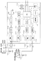
図8は、絶縁監視装置10のハードウェア構成図である。絶縁監視装置10は、単相変圧器3の低圧側である単相3線式の電灯回路(制御電源)から、コンセント122を介して制御電源入力部14に100[V]の交流電圧が入力される。また、絶縁監視装置10は、電流入力部12が2チャネル設けられ、第1チャネル12aが電灯回路に設けられる漏電センサ121に接続され、第2チャネル12bが3相変圧器2の低圧側に設けられる漏電センサ120に接続される。3相変圧器2の低圧側は3相3線の動力回路である。動力回路は、漏電センサ120を介してB種接地線で接地されており、第2チャネル12bを介して漏れ電流を絶縁監視装置10に入力する。絶縁監視装置10は、動力回路の接地線を被監視電路として、接地線の抵抗分漏れ電流Iorを測定することで絶縁状態を監視する。   FIG. 8 is a hardware configuration diagram of the insulation monitoring apparatus 10. The insulation monitoring device 10 receives an AC voltage of 100 [V] from the single-phase three-wire lamp circuit (control power supply) on the low-voltage side of the single-phase transformer 3 to the control power input unit 14 via the outlet 122. Is done. In addition, the insulation monitoring device 10 is provided with two channels of the current input unit 12, the first channel 12 a is connected to the leakage sensor 121 provided in the lamp circuit, and the second channel 12 b is provided on the low voltage side of the three-phase transformer 2. Connected to the leakage sensor 120. The low voltage side of the three-phase transformer 2 is a three-phase three-wire power circuit. The power circuit is grounded by a class B ground wire via the leakage sensor 120, and the leakage current is input to the insulation monitoring device 10 via the second channel 12b. The insulation monitoring device 10 monitors the insulation state by measuring the resistance leakage current Ior of the ground line using the ground line of the power circuit as the monitored electric circuit.

制御電源入力部14から入力される交流電圧は、電源トランス101及び位相トランス104に入力される。電源トランス101は、入力される100[V]の交流電圧を所定の電圧値の交流電圧に変換して、AC/DC部102に入力する。AC/DC部102は、電源トランス101で変換された交流電圧を直流電圧に変換して、レギュレータ103に入力する。レギュレータ103は、入力される直流電圧に応じて生成する直流の電源電圧VCC、VEEを他の装置に供給する。   The AC voltage input from the control power input unit 14 is input to the power transformer 101 and the phase transformer 104. The power transformer 101 converts an input AC voltage of 100 [V] into an AC voltage having a predetermined voltage value and inputs the AC voltage to the AC / DC unit 102. The AC / DC unit 102 converts the AC voltage converted by the power transformer 101 into a DC voltage and inputs the DC voltage to the regulator 103. The regulator 103 supplies DC power supply voltages VCC and VEE generated according to the input DC voltage to other devices.

位相トランス104は、入力される100[V]の交流電圧の位相を位相変換量に応じて変換して増幅器105に入力する。増幅器105は、位相変換後の交流電圧を増幅して、波形整形部106及びマルチプレクサ111に入力する。波形整形部106は、入力される交流電圧を波形整形して位相信号を生成し、CPU(Central Processing Unit)112に入力する。位相信号は、制御電源から入力されて位相が変換された交流電圧の電圧位相を表す。   The phase transformer 104 converts the phase of the input 100 [V] AC voltage according to the phase conversion amount and inputs the converted voltage to the amplifier 105. The amplifier 105 amplifies the AC voltage after phase conversion and inputs the amplified voltage to the waveform shaping unit 106 and the multiplexer 111. The waveform shaping unit 106 shapes the input AC voltage to generate a phase signal, and inputs the phase signal to a CPU (Central Processing Unit) 112. The phase signal represents the voltage phase of the AC voltage that has been input from the control power supply and whose phase has been converted.

電流入力部12の第1チャネル12aは、シャント抵抗107に接続される。シャント抵抗107は、漏電センサ121の漏れ電流の電流検出用の抵抗である。シャント抵抗107で検出される漏れ電流に応じた電圧は、増幅器108で増幅された後に、マルチプレクサ111に入力される。電流入力部12の第2チャネル12bは、シャント抵抗109に接続される。シャント抵抗109は、漏電センサ120の漏れ電流の電流検出用の抵抗である。シャント抵抗109で検出される漏れ電流に応じた電圧は、増幅器108で増幅された後に、マルチプレクサ111に入力される。   The first channel 12 a of the current input unit 12 is connected to the shunt resistor 107. The shunt resistor 107 is a resistor for detecting the leakage current of the leakage sensor 121. A voltage corresponding to the leakage current detected by the shunt resistor 107 is amplified by the amplifier 108 and then input to the multiplexer 111. The second channel 12 b of the current input unit 12 is connected to the shunt resistor 109. The shunt resistor 109 is a resistor for detecting the leakage current of the leakage sensor 120. A voltage corresponding to the leakage current detected by the shunt resistor 109 is amplified by the amplifier 108 and then input to the multiplexer 111.

マルチプレクサ111は、位相変換された交流電圧、及び漏電センサ120、121の漏れ電流に応じた電圧を入力とし、いずれかをCPU112に入力する。CPU112は、波形整形部106から入力される位相信号及びマルチプレクサ111から入力され漏電センサ120の漏れ電流に応じた電圧から、被監視電路の漏れ電流の電流値Iorを算出する。CPU112は、算出した漏れ電流の電流値Iorと所定値とを比較して、漏れ電流が所定値を超えた場合に被監視電路に絶縁不良が発生したと判定する。CPU112は、設定部15、表示部11、警報ランプ115、メモリ116、及び通信インタフェース(IF)117が接続される。設定部15は、キースイッチにより構成され、位相変換量の設定や絶縁状態を判定するための所定値の設定に用いられる。表示部11は、例えばLCD(Liquid Crystal Display)である。警報ランプ115は、絶縁不良の発生を光や音によりユーザに報知する。メモリ116は、CPU112で算出された漏れ電流の電流値Iorの保存、絶縁状態判定のための所定値の保存、位相変換量の保存に用いられる。通信IF117は、外部装置との通信を行い、外部装置に漏れ電流の電流値Iorや絶縁状態の判定結果を送信する。   The multiplexer 111 receives the AC voltage subjected to phase conversion and the voltage corresponding to the leakage currents of the leakage sensors 120 and 121, and inputs either of them to the CPU 112. The CPU 112 calculates the current value Ior of the leakage current of the monitored circuit from the phase signal input from the waveform shaping unit 106 and the voltage input from the multiplexer 111 and corresponding to the leakage current of the leakage sensor 120. The CPU 112 compares the calculated current value Ior of the leakage current with a predetermined value, and determines that an insulation failure has occurred in the monitored electric circuit when the leakage current exceeds the predetermined value. The CPU 112 is connected to a setting unit 15, a display unit 11, an alarm lamp 115, a memory 116, and a communication interface (IF) 117. The setting unit 15 includes a key switch, and is used for setting a phase conversion amount and setting a predetermined value for determining an insulation state. The display unit 11 is, for example, an LCD (Liquid Crystal Display). The warning lamp 115 notifies the user of the occurrence of insulation failure by light or sound. The memory 116 is used for storing the current value Ior of the leakage current calculated by the CPU 112, storing a predetermined value for determining the insulation state, and storing the phase conversion amount. The communication IF 117 performs communication with the external device, and transmits the leakage current value Ior and the insulation state determination result to the external device.

位相変換量は、例えば設定部15により直接入力される。この他に位相変換量は、例えばメモリ116に単相変圧器3の接続相及び3相変圧器2の結線の種類に応じた位相変換量を表すテーブルを格納しておき、設定部15から単相変圧器3の接続相及び3相変圧器2の結線の種類が入力されることで設定されてもよい。図8は第1チャネル12aに電灯回路が接続され、第2チャネル12bに動力回路が接続された構成であるが、位相変換量を変更することで、動力回路と電灯回路とを入れ替えることも可能である。   The phase conversion amount is directly input by the setting unit 15, for example. In addition to this, for example, the memory 116 stores a table indicating the phase conversion amount corresponding to the type of connection phase of the single-phase transformer 3 and the type of connection of the three-phase transformer 2 in the memory 116. It may be set by inputting the connection phase of the phase transformer 3 and the type of connection of the three-phase transformer 2. FIG. 8 shows a configuration in which a lamp circuit is connected to the first channel 12a and a power circuit is connected to the second channel 12b. However, the power circuit and the lamp circuit can be switched by changing the phase conversion amount. It is.

図9は、動力回路を被監視電路として、漏れ電流により被監視電路の絶縁状態を監視する絶縁監視装置10の機能ブロック図である。絶縁監視装置10は、例えばCPU112が所定のコンピュータプログラムを実行することで、上記のハードウェア構成により、電流検出部16、位相変換部17、Ior算出部18、及び制御部19として機能する。電流検出部16は、シャント抵抗109及び増幅器110により形成され、漏電センサ120から入力される漏れ電流を検出する。位相変換部17は、位相トランス104により形成され、設定部15により設定された位相変換量に応じて、制御電源から入力された交流電圧の位相を変換する。位相変換部17は、被監視電路の交流電圧の位相と同位相になるように、制御電源から入力された交流電圧の位相を変換する。   FIG. 9 is a functional block diagram of the insulation monitoring apparatus 10 that uses the power circuit as the monitored electric circuit and monitors the insulation state of the monitored electric circuit using the leakage current. The insulation monitoring device 10 functions as the current detection unit 16, the phase conversion unit 17, the Ior calculation unit 18, and the control unit 19 with the above hardware configuration, for example, when the CPU 112 executes a predetermined computer program. The current detection unit 16 is formed by a shunt resistor 109 and an amplifier 110 and detects a leakage current input from the leakage sensor 120. The phase conversion unit 17 is formed by the phase transformer 104 and converts the phase of the AC voltage input from the control power supply according to the phase conversion amount set by the setting unit 15. The phase conversion unit 17 converts the phase of the AC voltage input from the control power supply so as to be in phase with the phase of the AC voltage of the monitored circuit.

Ior算出部18及び制御部19は、CPU112により形成される。Ior算出部18は、電流検出部16で検出された電流と、位相が変換された交流電圧の電圧位相とから被監視電路の抵抗分漏れ電流の電流値Iorを算出する。
制御部19は、Ior算出部18で算出した漏れ電流の電流値Iorと所定値とを比較し、その結果により被監視電路の絶縁状態を判断する。例えば制御部19は、Ior算出部18で算出した漏れ電流の電流値Iorが所定値を超える場合、被監視電路が絶縁状態にないと判断し、所定値以下の場合、被監視電路が絶縁状態にあると判断する。制御部19は、絶縁状態の判断結果を表示部11に表示する。制御部19は、被監視電路が絶縁状態にない場合に出力部13に接続された装置へその旨を通知する。出力部13に接続された装置は、警報ランプ115や警報音の出力装置であり、被監視電路が絶縁状態にない場合に、光や音によりユーザに警報を発することで被監視装置が絶縁状態にないことを報知する。
The Ior calculation unit 18 and the control unit 19 are formed by the CPU 112. The Ior calculator 18 calculates the current value Ior of the resistance leakage current of the monitored circuit from the current detected by the current detector 16 and the voltage phase of the AC voltage whose phase has been converted.
The control unit 19 compares the current value Ior of the leakage current calculated by the Ior calculation unit 18 with a predetermined value, and determines the insulation state of the monitored circuit based on the result. For example, when the current value Ior of the leakage current calculated by the Ior calculation unit 18 exceeds a predetermined value, the control unit 19 determines that the monitored circuit is not in an insulated state. When the current value Ior is less than the predetermined value, the monitored circuit is in an insulated state. It is determined that The control unit 19 displays the determination result of the insulation state on the display unit 11. When the monitored circuit is not in an insulated state, the control unit 19 notifies the device connected to the output unit 13 to that effect. The device connected to the output unit 13 is an alarm lamp 115 or an alarm sound output device. When the monitored circuit is not in an insulated state, the monitored device is in an insulated state by issuing an alarm to the user by light or sound. Notify you that it is not.

従来のこの種の絶縁監視装置は、被監視電路の交流電圧及び漏れ電流が入力されて、この交流電圧の電圧位相と漏れ電流とにより抵抗分漏れ電流Iorを算出するように構成されている。これに対して本実施形態の絶縁監視装置10は、設定部15により設定された位相変換量に応じて制御電源から入力される交流電圧の位相を変換し、位相変換後の交流電圧の電圧位相と漏れ電流とにより抵抗分漏れ電流Iorを算出する。そのために絶縁監視装置10は、被監視電路の交流電圧の入力を必要としない。   This type of conventional insulation monitoring apparatus is configured to receive the AC voltage and leakage current of the monitored circuit and calculate the resistance leakage current Ior based on the voltage phase of the AC voltage and the leakage current. On the other hand, the insulation monitoring apparatus 10 of the present embodiment converts the phase of the AC voltage input from the control power supply according to the phase conversion amount set by the setting unit 15, and the voltage phase of the AC voltage after phase conversion. And the leakage current Ior is calculated from the leakage current. Therefore, the insulation monitoring apparatus 10 does not require the input of the AC voltage of the monitored electric circuit.

例えば高圧側がU−V相に接続された単相変圧器3を制御電源に用い、被監視電路がスター/デルタ結線の3相変圧器2の低圧側である場合、上記の通り、制御電源から供給される交流電圧の位相が被監視電路のu−v線間の電圧位相よりも30度進む。そのために、設定部15は、制御電源から入力される交流電圧の位相を30度遅らせるように位相変換量を設定する。これにより制御電源から入力される交流電圧と、被監視電路の交流電圧とが同位相になる。この電圧位相は、被監視電路の抵抗分漏れ電流Iorを算出するための同期検波用基準位相と同位相である。Ior算出部18は、このような電圧位相で被監視電路の漏れ電流を同期検波することでIor値を算出する。制御部19は、算出したIor値により3相電路の絶縁状態を監視する。   For example, when the single-phase transformer 3 whose high-voltage side is connected to the U-V phase is used as the control power source and the monitored circuit is the low-voltage side of the three-phase transformer 2 with star / delta connection, as described above, from the control power source The phase of the supplied AC voltage advances 30 degrees from the voltage phase between the uv lines of the monitored circuit. For this purpose, the setting unit 15 sets the phase conversion amount so as to delay the phase of the AC voltage input from the control power supply by 30 degrees. As a result, the AC voltage input from the control power supply and the AC voltage of the monitored circuit are in phase. This voltage phase is the same phase as the reference phase for synchronous detection for calculating the resistance leakage current Ior of the monitored circuit. The Ior calculation unit 18 calculates the Ior value by synchronously detecting the leakage current of the monitored circuit with such a voltage phase. The control unit 19 monitors the insulation state of the three-phase electric circuit based on the calculated Ior value.

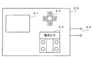
(電力測定器)
図10は、上記のような監視システムを応用した、被監視電路の電力を測定する電力測定器の外観図である。電力測定器20は、表示部21、電流入力部22、設定部23、及び制御電源入力部24を備える。この電力測定器20は、被監視電路である3相変圧器2の低圧側の電力を測定する。表示部21は、電圧位相の位相変換量設定時の設定画面や、電力の測定結果の表示を行う。電流入力部22は、被監視電路に流れる電流が入力される。設定部23は、制御電源から入力される交流電圧の位相を変換するための位相変換量を入力する入力装置である。制御電源入力部24は、制御電源から交流電圧が入力される。制御電源は、高圧側が3相電路のいずれか2相に接続される単相変圧器3であり、低圧側から、例えばAC100[V]の交流電圧を制御電源入力部24に入力する。
(Power meter)
FIG. 10 is an external view of a power measuring instrument that measures the power of the monitored electric circuit, to which the above monitoring system is applied. The power meter 20 includes a display unit 21, a current input unit 22, a setting unit 23, and a control power input unit 24. The power measuring device 20 measures the power on the low voltage side of the three-phase transformer 2 that is a monitored electric circuit. The display unit 21 displays a setting screen when setting the phase conversion amount of the voltage phase and a measurement result of the power. The current input unit 22 receives a current flowing through the monitored circuit. The setting unit 23 is an input device that inputs a phase conversion amount for converting the phase of the AC voltage input from the control power supply. The control power supply input unit 24 receives an AC voltage from the control power supply. The control power supply is a single-phase transformer 3 whose high-voltage side is connected to any two phases of a three-phase circuit, and an AC voltage of, for example, AC 100 [V] is input to the control power input unit 24 from the low-voltage side.

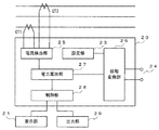
図11は、電力測定器20の機能ブロック図である。電力測定器20は、電流検出部25、位相変換部26、電力算出部27、及び制御部28として機能する。電流検出部25は、電流入力部22から入力される被監視電路のうちの2相の電流を検出する。位相変換部26は、設定部23により設定された位相変換量に応じて、制御電源から入力された交流電圧の位相を変換する。位相変換部26は、被監視電路の交流電圧の位相と同位相になるように、制御電源から入力された交流電圧の位相を変換する。電力算出部27は、電流検出部25で検出した電流と、位相変換部26で位相が変換された交流電圧の電圧位相とから被監視電路の電力を算出する。制御部28は、電力算出部27で算出された電力の算出結果を表示部21に出力し、所定のメモリに記録し、かつ出力部29から外部装置に出力する。   FIG. 11 is a functional block diagram of the power meter 20. The power measuring device 20 functions as a current detection unit 25, a phase conversion unit 26, a power calculation unit 27, and a control unit 28. The current detection unit 25 detects a two-phase current in the monitored electric circuit input from the current input unit 22. The phase conversion unit 26 converts the phase of the AC voltage input from the control power supply according to the phase conversion amount set by the setting unit 23. The phase conversion unit 26 converts the phase of the AC voltage input from the control power supply so as to be in phase with the phase of the AC voltage of the monitored circuit. The power calculator 27 calculates the power of the monitored circuit from the current detected by the current detector 25 and the voltage phase of the AC voltage whose phase is converted by the phase converter 26. The control unit 28 outputs the power calculation result calculated by the power calculation unit 27 to the display unit 21, records it in a predetermined memory, and outputs it from the output unit 29 to the external device.

従来のこの種の電力測定器は、被監視電路から交流電圧及び電流が入力されて、この交流電圧の電圧位相及び電流により電力を算出するように構成されている。これに対して本実施形態の電力測定器20は、設定部23により設定された位相変換量に応じて制御電源から入力される交流電圧の位相を変換し、位相変換後の交流電圧の電圧位相と被監視電路の電流とにより電力を算出する。そのために電力測定器20は、被監視電路の交流電圧の入力を必要としない。   This type of conventional power measuring device is configured to receive an AC voltage and current from a monitored circuit and calculate power based on the voltage phase and current of the AC voltage. On the other hand, the power measuring device 20 of the present embodiment converts the phase of the AC voltage input from the control power supply according to the phase conversion amount set by the setting unit 23, and the voltage phase of the AC voltage after phase conversion. And the power of the monitored circuit are calculated. Therefore, the power measuring device 20 does not need to input an AC voltage of the monitored circuit.

例えば高圧側がU−V相に接続された単相変圧器3を制御電源に用い、被監視電路がスター/デルタ結線の3相変圧器2の低圧側である場合、上記の通り、制御電源から供給される交流電圧の位相が被監視電路のu−v線間の電圧位相よりも30度進む。そのために、設定部23は、制御電源から入力される交流電圧の位相を30度遅らせるように位相変換量を設定する。これにより制御電源から入力される交流電圧と、被監視電路の交流電圧とが同位相になる。電力測定器20は、このように位相変換した交流電圧の電圧位相及び電流により被監視電路の電力値を算出する。   For example, when the single-phase transformer 3 whose high-voltage side is connected to the U-V phase is used as the control power source and the monitored circuit is the low-voltage side of the three-phase transformer 2 with star / delta connection, as described above, from the control power source The phase of the supplied AC voltage advances 30 degrees from the voltage phase between the uv lines of the monitored circuit. For this purpose, the setting unit 23 sets the phase conversion amount so as to delay the phase of the AC voltage input from the control power supply by 30 degrees. As a result, the AC voltage input from the control power supply and the AC voltage of the monitored circuit are in phase. The power measuring device 20 calculates the power value of the monitored circuit from the voltage phase and current of the AC voltage phase-converted in this way.

(潮流方向測定器)
図12は、上記のような監視システムを応用した、被監視電路の潮流方向を測定する潮流方向測定器の外観図である。潮流方向測定器30は、表示部31、電流入力部32、設定部33、及び制御電源入力部34を備える。この潮流方向測定器30は、被監視電路である3相変圧器2の低圧側の潮流方向を測定する。表示部31は、電圧位相の位相変換量設定時の設定画面や、潮流方向の測定結果の表示を行う。電流入力部32は、被監視電路に流れる電流が入力される。設定部33は、制御電源から入力される交流電圧の位相を変換するための位相変換量を入力する入力装置である。制御電源入力部34は、制御電源から交流電圧が入力される。制御電源は、高圧側が3相電路のいずれか2相に接続される単相変圧器3であり、低圧側から、例えばAC100[V]の交流電圧を制御電源入力部34に入力する。
(Tidal direction measuring device)
FIG. 12 is an external view of a tidal direction measuring device that measures the tidal direction of a monitored electric circuit to which the above monitoring system is applied. The power flow direction measuring device 30 includes a display unit 31, a current input unit 32, a setting unit 33, and a control power supply input unit 34. This tidal current direction measuring device 30 measures the tidal current direction on the low voltage side of the three-phase transformer 2 which is a monitored electric circuit. The display unit 31 displays a setting screen when setting the phase conversion amount of the voltage phase and a measurement result in the tidal direction. The current input unit 32 receives a current flowing through the monitored circuit. The setting unit 33 is an input device that inputs a phase conversion amount for converting the phase of the AC voltage input from the control power supply. The control power supply input unit 34 receives an AC voltage from the control power supply. The control power supply is a single-phase transformer 3 whose high-voltage side is connected to any two phases of a three-phase electric circuit, and an AC voltage of, for example, AC 100 [V] is input to the control power input unit 34 from the low-voltage side.

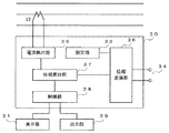
図13は、潮流方向測定器30の機能ブロック図である。潮流方向測定器30は、電流検出部35、位相変換部36、位相算出部37、及び制御部38として機能する。電流検出部35は、電流入力部32から入力される被監視電路のうちの1相の電流を検出する。位相変換部36は、設定部33により設定された位相変換量に応じて、制御電源から入力された交流電圧の位相を変換する。位相変換部36は、被監視電路の交流電圧の位相と同位相になるように、制御電源から入力された交流電圧の位相を変換する。位相算出部37は、電流検出部35で検出した電流と、位相変換部36で位相が変換された交流電圧の電圧位相とから被監視電路の位相を算出する。制御部38は、位相算出部37で算出された位相から潮流方向を測定し、測定結果を表示部31に出力し、所定のメモリに記録し、かつ出力部39から外部装置に出力する。   FIG. 13 is a functional block diagram of the tidal current direction measuring device 30. The power flow direction measuring device 30 functions as a current detection unit 35, a phase conversion unit 36, a phase calculation unit 37, and a control unit 38. The current detection unit 35 detects a one-phase current in the monitored electric circuit input from the current input unit 32. The phase conversion unit 36 converts the phase of the AC voltage input from the control power supply according to the phase conversion amount set by the setting unit 33. The phase conversion unit 36 converts the phase of the AC voltage input from the control power supply so as to be in phase with the phase of the AC voltage of the monitored circuit. The phase calculation unit 37 calculates the phase of the monitored circuit from the current detected by the current detection unit 35 and the voltage phase of the AC voltage whose phase is converted by the phase conversion unit 36. The control unit 38 measures the power flow direction from the phase calculated by the phase calculation unit 37, outputs the measurement result to the display unit 31, records it in a predetermined memory, and outputs it from the output unit 39 to the external device.

従来のこの種の潮流方向測定器は、被監視電路から交流電圧及び電流が入力されて、この交流電圧から電圧位相を算出して潮流方向を測定するように構成されている。これに対して本実施形態の潮流方向測定器30は、設定部33により設定された位相変換量に応じて制御電源から入力された交流電圧の位相を変換し、位相変換後の交流電圧の電圧位相と被監視電路の電流とにより潮流方向を測定する。そのために潮流方向測定器30は、被監視電路の交流電圧の入力を必要としない。   A conventional power flow direction measuring device of this type is configured to measure a power flow direction by inputting an alternating voltage and a current from a monitored circuit, calculating a voltage phase from the alternating voltage, and the like. On the other hand, the power flow direction measuring device 30 of the present embodiment converts the phase of the AC voltage input from the control power supply according to the phase conversion amount set by the setting unit 33, and the voltage of the AC voltage after the phase conversion. The direction of power flow is measured by the phase and current of the monitored circuit. Therefore, the power flow direction measuring device 30 does not require the input of the AC voltage of the monitored circuit.

例えば高圧側がU−V相に接続された単相変圧器3を制御電源に用い、被監視電路がスター/デルタ結線の3相変圧器2の低圧側である場合、上記の通り、制御電源から供給される交流電圧の位相が被監視電路のu−v線間の電圧位相よりも30度進む。そのために、設定部33は、制御電源から入力される交流電圧の位相を30度遅らせるように位相変換量を設定する。これにより制御電源から入力される交流電圧と、被監視電路の交流電圧とが同位相になる。潮流方向測定器30は、このように位相変換した交流電圧の電圧位相及び電流により被監視電路の潮流方向を測定する。   For example, when the single-phase transformer 3 whose high-voltage side is connected to the U-V phase is used as the control power source and the monitored circuit is the low-voltage side of the three-phase transformer 2 with star / delta connection, as described above, from the control power source The phase of the supplied AC voltage advances 30 degrees from the voltage phase between the uv lines of the monitored circuit. For this purpose, the setting unit 33 sets the phase conversion amount so as to delay the phase of the AC voltage input from the control power supply by 30 degrees. As a result, the AC voltage input from the control power supply and the AC voltage of the monitored circuit are in phase. The power flow direction measuring device 30 measures the power flow direction of the monitored electric circuit based on the voltage phase and current of the AC voltage phase-converted in this way.

(漏電方向測定器)
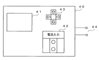
図14は、上記のような監視システムを応用した、被監視電路の漏電方向を測定する漏電方向測定器の外観図である。漏電方向測定器40は、表示部41、電流入力部42、設定部43、及び制御電源入力部44を備える。この漏電方向測定器40は、被監視電路である3相変圧器2の低圧側の漏電方向を測定する。表示部41は、電圧位相の位相変換量設定時の設定画面や、漏電方向の測定結果の表示を行う。電流入力部42は、被監視電路に流れる電流が入力される。設定部43は、制御電源から入力される交流電圧の位相を変換するための位相変換量を入力する入力装置である。制御電源入力部44は、制御電源から交流電圧が入力される。制御電源は、高圧側が3相電路のいずれか2相に接続される単相変圧器3であり、低圧側から、例えばAC100[V]の交流電圧を制御電源入力部44に入力する。
(Leakage direction measuring instrument)
FIG. 14 is an external view of a leakage direction measuring device that measures the leakage direction of the monitored electric circuit to which the above monitoring system is applied. The leakage direction measuring device 40 includes a display unit 41, a current input unit 42, a setting unit 43, and a control power supply input unit 44. This earth leakage direction measuring device 40 measures the earth leakage direction on the low voltage side of the three-phase transformer 2 which is a monitored electric circuit. The display unit 41 displays a setting screen when setting the phase conversion amount of the voltage phase and a measurement result of the leakage direction. The current input unit 42 receives a current flowing through the monitored electric circuit. The setting unit 43 is an input device that inputs a phase conversion amount for converting the phase of the AC voltage input from the control power supply. The control power input unit 44 receives an AC voltage from the control power. The control power supply is a single-phase transformer 3 whose high-voltage side is connected to any two phases of a three-phase electric circuit, and an AC voltage of, for example, AC 100 [V] is input to the control power input unit 44 from the low-voltage side.

図15は、漏電方向測定器40の機能ブロック図である。漏電方向測定器40は、電流検出部45、位相変換部46、位相算出部47、及び制御部48として機能する。電流検出部45は、電流入力部42から入力される3相の被監視電路の零相電流を検出する。位相変換部46は、設定部43により設定された位相変換量に応じて、制御電源から入力された交流電圧の位相を変換する。位相変換部46は、被監視電路の交流電圧の位相と同位相になるように、制御電源から入力された交流電圧の位相を変換する。位相算出部47は、電流検出部45で検出した電流と、位相変換部46で位相が変換された交流電圧の電圧位相とから被監視電路の位相を算出する。制御部48は、位相算出部47で算出された位相から漏電方向を測定し、測定結果を表示部41に出力し、所定のメモリに記録し、かつ出力部49から外部装置に出力する。   FIG. 15 is a functional block diagram of the leakage direction measuring device 40. The leakage direction measuring device 40 functions as a current detection unit 45, a phase conversion unit 46, a phase calculation unit 47, and a control unit 48. The current detection unit 45 detects the zero-phase current of the three-phase monitored circuit input from the current input unit 42. The phase conversion unit 46 converts the phase of the AC voltage input from the control power supply according to the phase conversion amount set by the setting unit 43. The phase converter 46 converts the phase of the AC voltage input from the control power supply so as to be in phase with the phase of the AC voltage of the monitored circuit. The phase calculation unit 47 calculates the phase of the monitored circuit from the current detected by the current detection unit 45 and the voltage phase of the AC voltage whose phase is converted by the phase conversion unit 46. The control unit 48 measures the leakage direction from the phase calculated by the phase calculation unit 47, outputs the measurement result to the display unit 41, records it in a predetermined memory, and outputs it from the output unit 49 to the external device.

従来のこの種の漏電方向測定器は、被監視電路から高圧の交流電圧を絶縁して入力し、被監視電路の漏れ電流値及び漏電方向を算出するように構成されている。これに対して本実施形態の漏電方向測定器40は、設定部43により設定された位相に、制御電源から入力される交流電圧の位相を変換し、位相変換後の交流電圧の電圧位相と被監視電路の電流とにより漏れ電流値及び漏電方向を算出する。そのために漏電方向測定器40は、被監視電路の交流電圧の入力を必要としない。   This type of conventional leakage direction measuring instrument is configured to input a high-voltage AC voltage isolated from the monitored circuit and calculate a leakage current value and a leakage direction of the monitored circuit. On the other hand, the leakage direction measuring instrument 40 of the present embodiment converts the phase of the AC voltage input from the control power source into the phase set by the setting unit 43, and the voltage phase of the AC voltage after the phase conversion and the target voltage are converted. The leakage current value and leakage direction are calculated from the current in the monitoring circuit. Therefore, the leakage direction measuring instrument 40 does not require the input of the AC voltage of the monitored circuit.

例えば高圧側がU−V相に接続された単相変圧器3を制御電源に用い、被監視電路が3相変圧器2のスター/デルタ結線の低圧側である場合、上記の通り、制御電源から供給される交流電圧の位相が被監視電路のu−v線間の電圧位相よりも30度進む。そのために、設定部43は、制御電源から入力される交流電圧の位相を30度遅らせるように位相変換量を設定する。これにより制御電源から入力される交流電圧と、被監視電路の交流電圧とが同位相になる。漏電方向測定器40は、このように位相変換した交流電圧の電圧位相及び電流により被監視電路の漏電方向を測定する。   For example, when the single-phase transformer 3 whose high-voltage side is connected to the U-V phase is used as the control power source and the monitored circuit is the low-voltage side of the star / delta connection of the three-phase transformer 2, the control power source The phase of the supplied AC voltage advances 30 degrees from the voltage phase between the uv lines of the monitored circuit. For this purpose, the setting unit 43 sets the phase conversion amount so as to delay the phase of the AC voltage input from the control power supply by 30 degrees. As a result, the AC voltage input from the control power supply and the AC voltage of the monitored circuit are in phase. The leakage direction measuring instrument 40 measures the leakage direction of the monitored circuit from the voltage phase and current of the AC voltage thus phase-converted.

以上のように本実施形態の監視装置1では、制御電源から入力される交流電圧の位相変換量を、制御電源である単相変圧器3の高圧側の接続相と、低圧側が被監視電路となる3相変圧器2の結線の種類との組み合わせにより設定することができる。監視装置1は、制御電源から入力される交流電圧を位相変換量に応じて位相変換し、位相変換後の交流電圧の電圧位相と被監視電路の電流とにより、被監視電路の監視が可能となる。そのために監視装置1は、充電部に接触することなく、安全に、低コストで被監視電路の電圧位相を取得することが可能となり、被監視電路の電気的状態を監視することができる。   As described above, in the monitoring device 1 according to the present embodiment, the phase conversion amount of the AC voltage input from the control power supply is determined based on the connection phase on the high-voltage side of the single-phase transformer 3 that is the control power supply, and the monitored circuit on the low-voltage side. It can set by the combination with the kind of connection of the three-phase transformer 2 which becomes. The monitoring device 1 phase-converts the AC voltage input from the control power supply according to the phase conversion amount, and can monitor the monitored circuit by the voltage phase of the AC voltage after phase conversion and the current of the monitored circuit. Become. Therefore, the monitoring device 1 can obtain the voltage phase of the monitored electric circuit safely and at low cost without contacting the charging unit, and can monitor the electrical state of the monitored electric circuit.

(漏れ電流計測器)
以上の説明では、監視装置1が被監視電路の交流電流と制御電源の交流電圧とを入力として、被監視線路の電気的状態を監視している。監視装置1は、制御電源の交流電圧を用いずに、被監視電路の電気的状態を監視することも可能である。図16は、被監視線路の交流電流と、3相電路のいずれかの相の高圧ケーブル接地線に流れる接地線電流(充電電流)とにより、被監視線路の電気的状態を監視する監視システムの構成図である。高圧ケーブルは、例えば高圧CVTケーブルである。
(Leakage current measuring instrument)
In the above description, the monitoring device 1 monitors the electrical state of the monitored line using the AC current of the monitored circuit and the AC voltage of the control power supply as inputs. The monitoring device 1 can also monitor the electrical state of the monitored circuit without using the AC voltage of the control power supply. FIG. 16 shows a monitoring system for monitoring the electrical state of the monitored line by the alternating current of the monitored line and the ground line current (charging current) flowing through the high-voltage cable ground line of any phase of the three-phase circuit. It is a block diagram. The high voltage cable is, for example, a high voltage CVT cable.

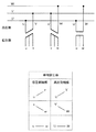
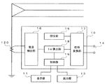
図16(a)は、3相変圧器2の低圧側である動力電路の抵抗分漏れ電流Iorを測定する監視システムの構成図である。図16(b)は、単相変圧器3の低圧側である電灯電路の抵抗分漏れ電流Iorを測定する監視システムの構成図である。監視装置1は、測定した抵抗分漏れ電流Iorにより被監視電路(動力電路、電灯電路)の絶縁状態を監視することができる。   FIG. 16A is a configuration diagram of a monitoring system that measures the resistance leakage current Ior of the power circuit that is the low voltage side of the three-phase transformer 2. FIG. 16B is a configuration diagram of a monitoring system that measures the resistance leakage current Ior of the lamp circuit that is the low-voltage side of the single-phase transformer 3. The monitoring device 1 can monitor the insulation state of the monitored circuit (power circuit, lamp circuit) based on the measured resistance leakage current Ior.

そのために監視装置1は、動力電路や電灯電路の接地線電流を検出する第1電流検出部55と、3相電路のいずれかの電路の高圧ケーブル接地線に流れる接地線電流を検出する第2電流検出部56と、動力電路や電灯電路の電気的状態を監視する監視部57と、表示部58とを備える。監視部57は、動力電路や電灯電路の接地線電流と、3相電路のいずれかの電路の高圧ケーブル接地線に流れる接地線電流とにより、動力電路や電灯電路の抵抗分漏れ電流Iorを測定する。監視部57は、抵抗分漏れ電流Iorの測定結果に応じて、被監視電路の絶縁状態を判断する。監視装置1は、抵抗分漏れ電流Iorの測定結果や、被監視電路の絶縁状態の判断結果を表示部58に表示することで、ユーザに監視結果を報知する。   For this purpose, the monitoring device 1 detects the ground line current flowing in the high-voltage cable ground line of one of the three-phase electric circuits and the first current detection unit 55 that detects the ground line current of the power circuit and the lamp circuit. A current detection unit 56, a monitoring unit 57 that monitors the electrical state of the power circuit and the lamp circuit, and a display unit 58 are provided. The monitoring unit 57 measures the resistance leakage current Ior of the power circuit and the lamp circuit from the ground line current of the power circuit and the lamp circuit and the ground line current flowing through the high-voltage cable ground line of any of the three-phase circuits. To do. The monitoring unit 57 determines the insulation state of the monitored electric circuit according to the measurement result of the resistance leakage current Ior. The monitoring device 1 notifies the user of the monitoring result by displaying the measurement result of the resistance leakage current Ior and the determination result of the insulation state of the monitored electric circuit on the display unit 58.

図16(a)に示す構成の場合、第1電流検出部55は、3相変圧器2の接地線(B種接地線)にクランプされる変流器(CT:Current Transformer)51から、動力電路の接地線電流Io(B種接地線電流Io)を検出する。第2電流検出部56は、3相変圧器2の高圧側の3相電路のいずれか1相の高圧ケーブル接地線にクランプされる補助変流器52から、接地線電流を検出する。図16(a)では補助変流器52がU相の高圧ケーブル接地線にクランプされている。第2電流検出部56は、U相の高圧ケーブル接地線に流れる接地線電流を検出する。ここで、例えばU相の高圧ケーブル接地線に流れる接地線電流は、U相の交流電圧よりも位相が90度進んでいる。監視部57は、このU相の高圧ケーブル接地線に流れる接地線電流の位相でB種接地線電流Ioを同期検波することで、動力電路の抵抗分漏れ電流Iorを測定する。   In the case of the configuration shown in FIG. 16A, the first current detection unit 55 receives power from a current transformer (CT: Current Transformer) 51 that is clamped to the ground line (B-type ground line) of the three-phase transformer 2. The ground line current Io (B-type ground line current Io) of the electric circuit is detected. The second current detection unit 56 detects the ground line current from the auxiliary current transformer 52 clamped to the high-voltage cable ground line of any one of the three-phase electric circuits on the high-voltage side of the three-phase transformer 2. In FIG. 16A, the auxiliary current transformer 52 is clamped to the U-phase high-voltage cable ground line. The second current detector 56 detects a ground line current flowing through the U-phase high-voltage cable ground line. Here, for example, the phase of the ground line current flowing through the U-phase high-voltage cable ground line is 90 degrees ahead of the U-phase AC voltage. The monitoring unit 57 measures the resistance leakage current Ior of the power circuit by synchronously detecting the B-type grounding line current Io with the phase of the grounding line current flowing through the U-phase high-voltage cable grounding line.

図17は、位相の説明図である。3相変圧器2がスター/デルタ結線の場合、高圧側のVUN(中点NからU相を見た電圧)と、低圧側のVuw(w相からu相を見た電圧)とは、同相である。中点Nは接地である。3相変圧器2の低圧側のv相からw−u相の中点の位相を見た電圧Vpが、動力電路の抵抗分漏れ電流Iorの位相方向になる。そのために監視部57は、電圧Vpの位相でB種接地線電流Ioを同期検波することで、動力電路の抵抗分漏れ電流Iorを測定することができる。監視部57は、動力電路のv相のB種接地線電流Ioを検出する場合、高圧側のU相の高圧ケーブル接地線に流れる接地線電流の位相によりB種接地線電流Ioを同期検波することで、動力電路の抵抗分漏れ電流Iorを測定することができる。動力電路の他の相(u相、w相)についても同様に、B種接地線電流Ioが高圧側の高圧ケーブル接地線に流れる接地線電流の位相により同期検波されて測定可能である。   FIG. 17 is an explanatory diagram of the phase. When the three-phase transformer 2 is a star / delta connection, the VUN on the high voltage side (voltage seen from the midpoint N to the U phase) and the Vuw on the low voltage side (voltage seen from the w phase to the u phase) are in phase It is. Midpoint N is ground. The voltage Vp obtained by viewing the phase of the midpoint of the wu phase from the v phase on the low voltage side of the three-phase transformer 2 is in the phase direction of the resistance leakage current Ior of the power circuit. Therefore, the monitoring unit 57 can measure the resistance leakage current Ior of the power circuit by synchronously detecting the B-type ground line current Io with the phase of the voltage Vp. When detecting the v-phase B-type ground line current Io of the power circuit, the monitoring unit 57 synchronously detects the B-type ground line current Io based on the phase of the ground-line current flowing in the high-voltage U-phase high-voltage cable ground line. Thus, the resistance leakage current Ior of the power circuit can be measured. Similarly, for the other phases (u phase, w phase) of the power circuit, the B-type ground line current Io can be measured by being synchronously detected by the phase of the ground line current flowing through the high-voltage cable ground line.

図16(b)に示す構成の場合、第1電流検出部55は、単相変圧器3の接地線(B種接地線)にクランプされる変流器61から、電灯電路のB種接地線電流Ioを検出する。第2電流検出部56は、単相変圧器3の高圧側の3相電路のうちの2相の接地線にクランプされる補助変流器62から2相の接地線電流(充電電流)の和を検出する。充電電流を検出する高圧側の3相電路のうちの2相は、単相変圧器3に入力される2相である。単相変圧器3は、高圧側の3相電路において接続相がU−V相、V−W相、W−U相の3種類である。単相変圧器3の接続相がU−V相の場合、補助変流器62は、3相電路のU相及びV相の2相の接地線をクランプする。単相変圧器3の接続相がV−W相の場合、補助変流器62は、3相電路のV相及びW相の2相の接地線をクランプする。単相変圧器3の接続相がW−U相の場合、補助変流器62は、3相電路のW相及びU相の2相の接地線をクランプする。   In the case of the configuration shown in FIG. 16B, the first current detection unit 55 is connected to the B-type ground wire of the lamp circuit from the current transformer 61 clamped to the ground wire (B-type ground wire) of the single-phase transformer 3. The current Io is detected. The second current detection unit 56 adds the two-phase ground line current (charging current) from the auxiliary current transformer 62 clamped to the two-phase ground line of the three-phase electric circuit on the high-voltage side of the single-phase transformer 3. Is detected. Two phases of the three-phase electric circuit on the high voltage side for detecting the charging current are two phases input to the single-phase transformer 3. The single-phase transformer 3 has three types of connection phases of a U-V phase, a V-W phase, and a W-U phase in a three-phase electric circuit on the high voltage side. When the connection phase of the single-phase transformer 3 is the U-V phase, the auxiliary current transformer 62 clamps the U-phase and V-phase two-phase ground lines of the three-phase electric circuit. When the connection phase of the single-phase transformer 3 is the V-W phase, the auxiliary current transformer 62 clamps the two-phase ground wires of the V-phase and the W-phase of the three-phase electric circuit. When the connection phase of the single-phase transformer 3 is the W-U phase, the auxiliary current transformer 62 clamps the two-phase ground wires of the W-phase and the U-phase of the three-phase electric circuit.

例えば単相変圧器3の接続相がW−U相の場合、補助変流器62は3相電路のW相及びU相の2相の接地線をクランプする。W相及びU相の充電電流の位相は、W相及びU相の線間電圧の位相と同位相である。図4に示すように、単相変圧器3の高圧側と低圧側とは電圧位相が同相である。そのために、W相及びU相の充電電流の位相は、単相変圧器3の低圧側のw相及びu相の線間電圧と同位相となる。従って、監視部57は、W相及びU相の加算電流の位相でB種接地線電流Ioを同期検波することで、電灯電路の抵抗分漏れ電流Iorを測定することができる。   For example, when the connection phase of the single-phase transformer 3 is the W-U phase, the auxiliary current transformer 62 clamps the W-phase and U-phase two-phase ground wires of the three-phase circuit. The phases of the W-phase and U-phase charging currents are in phase with the W-phase and U-phase line voltage phases. As shown in FIG. 4, the voltage phase of the high-voltage side and the low-voltage side of the single-phase transformer 3 is the same phase. Therefore, the phases of the W-phase and U-phase charging currents are in phase with the low-phase w-phase and u-phase line voltages of the single-phase transformer 3. Therefore, the monitoring unit 57 can measure the resistance leakage current Ior of the lamp circuit by synchronously detecting the B-type ground line current Io with the phase of the W-phase and U-phase added currents.

図18は、位相の説明図である。例えば単相変圧器3の高圧側の接続相がU−V相である場合、3相電路のU相及びV相の充電電流のベクトル和ICUV(U相とV相の充電電流の和)が、単相変圧器3の低圧側の線間電圧の位相と同位相になる。従って、ベクトル和ICUVで電灯電路のB種接地線のB種接地線電流Ioを同期検波することで、電灯電路の抵抗分漏れ電流Iorが測定される。同様に、単相変圧器3の高圧側の接続相がV−W相である場合、3相電路のV相及びW相の充電電流のベクトル和ICVWが、単相変圧器3の低圧側の線間電圧の位相と同位相になる。単相変圧器3の高圧側の接続相がW−U相である場合、3相電路のW相及びU相の充電電流のベクトル和ICWUが、単相変圧器3の低圧側の線間電圧の位相と同位相になる。単相変圧器3の高圧側の接続相と3相電路の充電電流の位相とを合わせるために、容易に目視確認ができる。   FIG. 18 is an explanatory diagram of phases. For example, when the connection phase on the high voltage side of the single-phase transformer 3 is the U-V phase, the vector sum ICUV (sum of the U-phase and V-phase charge currents) of the U-phase and V-phase charge currents of the three-phase circuit is The phase of the line voltage on the low voltage side of the single-phase transformer 3 is the same as the phase. Therefore, the resistance leakage current Ior of the lamp circuit is measured by synchronously detecting the class B ground line current Io of the class B ground line of the lamp circuit with the vector sum ICUV. Similarly, when the connection phase on the high-voltage side of the single-phase transformer 3 is the V-W phase, the vector sum I CVW of the V-phase and W-phase charging currents of the three-phase circuit is The phase is the same as the phase of the line voltage. When the connection phase on the high-voltage side of the single-phase transformer 3 is the W-U phase, the vector sum ICWU of the charging currents of the W-phase and U-phase of the three-phase circuit is the line voltage on the low-voltage side of the single-phase transformer 3 It becomes the same phase as. Since the connecting phase on the high-voltage side of the single-phase transformer 3 and the phase of the charging current of the three-phase circuit are matched, visual confirmation can be easily performed.

以上の説明では、各変圧器(3相変圧器2及び単相変圧器3)の高圧側の3相電路の相電圧が、U、V、Wを正三角形の頂点とし、接地(大地)を正三角形の中点Nとして表されている。高電圧側の3相電路の各相の対地間静電容量が同じ場合、接地の位置が正三角形の中点になるが、通常、3相電路の各相の対地間静電容量は同じではなくバラツキがある。正三角形の中点と、対地間静電容量のバラツキにより生じる接地との差Voは、監視対象の電路の電気的状態(抵抗分漏れ電流Ior)の誤差となる。   In the above description, the phase voltage of the three-phase circuit on the high voltage side of each transformer (the three-phase transformer 2 and the single-phase transformer 3) is such that U, V, and W are the vertices of an equilateral triangle, and the ground (ground) is It is represented as the midpoint N of the equilateral triangle. If the ground-to-ground capacitance of each phase of the three-phase circuit on the high voltage side is the same, the grounding position will be the midpoint of the equilateral triangle, but usually the capacitance to ground of each phase of the three-phase circuit is not the same. There is no variation. The difference Vo between the midpoint of the equilateral triangle and the ground caused by the variation in the capacitance between the grounds is an error in the electrical state (resistance leakage current Ior) of the monitored electric circuit.

差Voは、通常1〜2%である。低圧側のB種接地線電流Ioが100[mA]の場合、差Voが2[%]であれば、位相角が最大1.146度ずれる。B種接地線電流Ioがすべて充電電流である場合、差Voによる抵抗分漏れ電流Iorの誤差は、最大2[mA]である。抵抗分漏れ電流Iorの誤差の規格(監視装置1を取り付けた場合の計測器として隔月点検時における誤差)は10[%]であり、基準値が50[mA]であるため、3相電路の各相の対地間静電容量が同じではない場合の誤差は、問題になることはない。   The difference Vo is usually 1-2%. When the low-voltage B-type ground line current Io is 100 [mA] and the difference Vo is 2 [%], the phase angle is shifted by 1.146 degrees at the maximum. When all the B-type ground line currents Io are charging currents, the error of the resistance leakage current Ior due to the difference Vo is 2 [mA] at the maximum. The standard of the error of the resistance leakage current Ior (the error at the time of bimonthly inspection as a measuring instrument when the monitoring device 1 is attached) is 10 [%], and the reference value is 50 [mA]. Errors in the case where the ground-to-ground capacitances of each phase are not the same will not be a problem.

従来の漏れ電流計測器は、例えば動力電路に設けられるMCCB(Molded Case Circuit Breaker)により動力電路の電圧成分を検出し、B種接地線に設けられるZCT(Zero-phase Current Transformer)によりB種接地線の電流成分を検出して、動力電路の抵抗分漏れ電流Iorを測定する。或いは漏れ電流計測器は、100[V]や200[V]の交流電圧を電源から取り込み、位相をずらして動力電路の抵抗分漏れ電流Iorを測定する。   For example, a conventional leakage current measuring device detects a voltage component of a power circuit by using a MCCB (Molded Case Circuit Breaker) provided in the power circuit, and class B grounding by a ZCT (Zero-phase Current Transformer) provided in a class B ground line. The resistance component leakage current Ior of the power circuit is measured by detecting the current component of the line. Alternatively, the leakage current measuring instrument takes in an AC voltage of 100 [V] or 200 [V] from the power source, and measures the resistance leakage current Ior of the power circuit by shifting the phase.

このように従来の漏れ電流計測器は100[V]や200[V]の交流電圧を取得する必要があり、動力電路の抵抗分漏れ電流Iorの測定に危険が伴う。これに対して本実施形態の監視装置1は、2個の変流器を3相電路、動力電路、電灯電路にクランプすることで交流電流を取得し、これらの交流電流に応じて抵抗分漏れ電流Iorを測定する。そのために交流電圧を取得する必要がなく、安全に抵抗分漏れ電流Iorを測定することができる。   Thus, the conventional leakage current measuring instrument needs to acquire an AC voltage of 100 [V] or 200 [V], and there is a danger in measuring the resistance leakage current Ior of the power circuit. On the other hand, the monitoring device 1 according to the present embodiment acquires an alternating current by clamping two current transformers to a three-phase electric circuit, a power electric circuit, and a lamp electric circuit, and leaks resistance in accordance with these alternating currents. The current Ior is measured. Therefore, it is not necessary to acquire an AC voltage, and the resistance leakage current Ior can be measured safely.

1…監視装置、2…3相変圧器、3…単相変圧器、10…絶縁監視装置、20…電力測定器、30…潮流方向測定器、40…漏電方向測定器、11,21,31,41,58…表示部、12,22,32,42…電流入力部、13,29,39,49…出力部、14,24,34,44…制御電源入力部、15,23,33,43…設定部、16,25,35,45…電流検出部、17,26,36,46…位相変換部、18…Ior算出部、19,28,38,48…制御部、27…電力算出部、37,47…位相算出部、51,61…変流器、52,62…補助変流器、55…第1電流検出部、56…第2電流検出部、57…監視部   DESCRIPTION OF SYMBOLS 1 ... Monitoring device, 2 ... Three-phase transformer, 3 ... Single phase transformer, 10 ... Insulation monitoring device, 20 ... Power measuring device, 30 ... Power flow direction measuring device, 40 ... Electric leakage direction measuring device, 11, 21, 31 , 41, 58 ... display section, 12, 22, 32, 42 ... current input section, 13, 29, 39, 49 ... output section, 14, 24, 34, 44 ... control power input section, 15, 23, 33, 43 ... setting unit, 16, 25, 35, 45 ... current detection unit, 17, 26, 36, 46 ... phase conversion unit, 18 ... Ior calculation unit, 19, 28, 38, 48 ... control unit, 27 ... power calculation , 37, 47 ... phase calculation unit, 51, 61 ... current transformer, 52, 62 ... auxiliary current transformer, 55 ... first current detection unit, 56 ... second current detection unit, 57 ... monitoring unit

Claims (8)

高圧側が3相電路に接続された変圧器の低圧側の電路の第1接地線電流を検出する第1検出手段と、
前記3相電路のいずれかの電路の高圧ケーブル接地線に流れる第2接地線電流を検出する第2検出手段と、
前記第2接地線電流の位相により前記第1接地線電流を同期検波することで、前記変圧器の前記低圧側の電気的状態を監視する監視手段と、を備えることを特徴とする、
監視装置。
First detection means for detecting a first ground line current of a low-voltage side circuit of the transformer, the high-voltage side of which is connected to a three-phase circuit;
Second detection means for detecting a second ground line current flowing in the high-voltage cable ground line of any one of the three-phase electric circuits;
Monitoring means for monitoring the electrical state of the low-voltage side of the transformer by synchronously detecting the first ground line current according to the phase of the second ground line current,
Monitoring device.
前記第1検出手段は、前記第1接地線電流として、B種接地された前記変圧器の前記低圧側の前記電路からB種接地線電流を検出し、
前記監視手段は、前記第2接地線電流の位相により前記B種接地線電流を同期検波することで、前記変圧器の前記低圧側の抵抗分漏れ電流を測定することを特徴とする、
請求項1記載の監視装置。
The first detection means detects a type B ground line current from the electric circuit on the low voltage side of the transformer grounded as a type B as the first ground line current,
The monitoring means measures the resistance leakage current on the low-voltage side of the transformer by synchronously detecting the type B ground line current according to the phase of the second ground line current.
The monitoring device according to claim 1.
前記監視手段は、測定した抵抗分漏れ電流に応じて、前記変圧器の前記低圧側の前記電路の絶縁状態を監視することを特徴とする、
請求項2記載の監視装置。
The monitoring means monitors the insulation state of the electric circuit on the low-voltage side of the transformer according to the measured resistance leakage current,
The monitoring device according to claim 2.
前記電路の絶縁状態の監視結果を表示する表示手段を更に備えることを特徴とする、
請求項3記載の監視装置。
It further comprises display means for displaying the monitoring result of the insulation state of the electric circuit,
The monitoring device according to claim 3.
前記第1検出手段は、3相変圧器の低圧側の動力電路の前記第1接地線電流を検出し、
前記第2検出手段は、前記3相電路のいずれか1相の高圧ケーブル接地線から前記第2接地線電流を検出し、
前記監視手段は、前記動力電路の抵抗分漏れ電流を測定することを特徴とする、
請求項1〜4のいずれか1項記載の監視装置。
The first detection means detects the first ground line current of the power circuit on the low voltage side of the three-phase transformer,
The second detection means detects the second ground line current from the high-voltage cable ground line of any one phase of the three-phase electric circuit,
The monitoring means measures a resistance leakage current of the power circuit,
The monitoring apparatus of any one of Claims 1-4.
前記第1検出手段は、前記動力電路の接地線にクランプされた変流器から前記第1接地線電流を検出し、
前記第2検出手段は、前記3相電路のいずれか1相の高圧ケーブル接地線にクランプされた変流器から前記第2接地線電流を検出することを特徴とする、
請求項5記載の監視装置。
The first detection means detects the first ground line current from a current transformer clamped to the ground line of the power circuit,
The second detection means detects the second ground line current from a current transformer clamped to a high-voltage cable ground line of any one phase of the three-phase electric circuit,
The monitoring device according to claim 5.
前記第1検出手段は、単相変圧器の低圧側の電灯電路の前記第1接地線電流を検出し、
前記第2検出手段は、前記3相電路のいずれか2相の接地線から前記第2接地線電流を検出し、
前記監視手段は、前記電灯電路の抵抗分漏れ電流を測定することを特徴とする、
請求項1〜4のいずれか1項記載の監視装置。
The first detection means detects the first ground line current of the electric lamp circuit on the low voltage side of the single-phase transformer,
The second detection means detects the second ground line current from any two-phase ground line of the three-phase electric circuit,
The monitoring means measures a resistance leakage current of the lamp electric circuit,
The monitoring apparatus of any one of Claims 1-4.
前記第1検出手段は、前記電灯電路の接地線にクランプされた変流器から前記第1接地線電流を検出し、
前記第2検出手段は、前記3相電路のいずれか2相の接地線にクランプされた変流器から前記第2接地線電流を検出することを特徴とする、
請求項7記載の監視装置。
The first detection means detects the first ground line current from a current transformer clamped to the ground line of the lamp electric circuit,
The second detection means detects the second ground line current from a current transformer clamped to any two-phase ground line of the three-phase electric circuit,
The monitoring device according to claim 7.
JP2017081904A 2016-04-19 2017-04-18 Monitoring device Pending JP2017194465A (en)

Applications Claiming Priority (2)

Application Number Priority Date Filing Date Title
JP2016083776 2016-04-19

Publications (1)

Publication Number Publication Date
JP2017194465A true JP2017194465A (en) 2017-10-26

Family

ID=60155474

Family Applications (1)

Application Number Title Priority Date Filing Date
JP2017081904A Pending JP2017194465A (en) 2016-04-19 2017-04-18 Monitoring device

Country Status (1)

Country Link
JP (1) JP2017194465A (en)

Cited By (3)

* Cited by examiner, † Cited by third party
Publication number Priority date Publication date Assignee Title
CN107918079A (en) * 2017-11-17 2018-04-17 云南电网有限责任公司电力科学研究院 A kind of one-phase earthing failure in electric distribution network localization method and system based on frequency sweep injection
CN109066970A (en) * 2018-07-18 2018-12-21 国家电网公司华中分部 A kind of transmission cross-section dynamic monitoring and controlling method based on expert system
CN110297154A (en) * 2019-07-18 2019-10-01 国电南瑞科技股份有限公司 Earth fault line selection method and device based on zero mould current temporary state energy

Cited By (5)

* Cited by examiner, † Cited by third party
Publication number Priority date Publication date Assignee Title
CN107918079A (en) * 2017-11-17 2018-04-17 云南电网有限责任公司电力科学研究院 A kind of one-phase earthing failure in electric distribution network localization method and system based on frequency sweep injection
CN107918079B (en) * 2017-11-17 2021-03-12 云南电网有限责任公司电力科学研究院 Method and system for single-phase grounding fault location in distribution network based on sweep frequency injection
CN109066970A (en) * 2018-07-18 2018-12-21 国家电网公司华中分部 A kind of transmission cross-section dynamic monitoring and controlling method based on expert system
CN110297154A (en) * 2019-07-18 2019-10-01 国电南瑞科技股份有限公司 Earth fault line selection method and device based on zero mould current temporary state energy
CN110297154B (en) * 2019-07-18 2021-09-10 国电南瑞科技股份有限公司 Small current ground fault line selection method and device based on zero-mode current transient energy

Similar Documents

Publication Publication Date Title
TWI557412B (en) Leakage current calculation device and leakage current calculation method
JP5544517B2 (en) Leakage current measuring device and measuring method in electrical equipment
US9829519B2 (en) Method and apparatus to commission voltage sensors and branch circuit current sensors for branch circuit monitoring systems
KR100896091B1 (en) Earth resistive leakage current measuring instrument
KR20080093169A (en) Leakage current measurement and leakage current interruption method by phase angle calculation
JP6373019B2 (en) Simulated power supply device and normal weighing confirmation device
US9897647B2 (en) Method and apparatus to commission voltage sensors and branch circuit current sensors for branch circuit monitoring systems
JP5449895B2 (en) Leakage current measuring device
JPWO2018167909A1 (en) Leakage current detection device, method, and program for detecting leakage current
JP5380702B2 (en) Leakage current measuring device and measuring method
JP2023021267A (en) Detection device, method, and program
JP4599120B2 (en) Electrical installation insulation monitoring device and method
JP2017194465A (en) Monitoring device
JP6240918B1 (en) Leakage current measuring method and leakage current measuring device
JP5477020B2 (en) Leakage current measuring device and measuring method in electrical equipment
JP4993728B2 (en) Effective leakage current measuring instrument
JP6704368B2 (en) Insulation monitoring device, method and program
JP2010060329A (en) Apparatus and method for measuring leakage current of electrical path and electric instrument
JP2009058235A (en) Leak current measuring instrument for electric path and electric apparatus, and its method
JP2008309681A (en) Insulation degradation monitoring device and method
JPH11287836A (en) Compound measuring device of power supply circuit
JP5679480B2 (en) Indirect AC megger measuring instrument and insulation resistance measuring method
JPS62209371A (en) Method and apparatus for live wire type measurement of insulation resistance
JP2014010077A (en) Testing device for insulation monitoring device, insulation monitoring device and testing method for insulation monitoring device
JP2005201854A (en) Electric power measurement method and apparatus