JP2017194810A - Remote monitoring system - Google Patents
Remote monitoring system Download PDFInfo
- Publication number
- JP2017194810A JP2017194810A JP2016084156A JP2016084156A JP2017194810A JP 2017194810 A JP2017194810 A JP 2017194810A JP 2016084156 A JP2016084156 A JP 2016084156A JP 2016084156 A JP2016084156 A JP 2016084156A JP 2017194810 A JP2017194810 A JP 2017194810A
- Authority
- JP
- Japan
- Prior art keywords
- data acquisition
- external connection
- remote monitoring
- acquisition device
- monitoring system
- Prior art date
- Legal status (The legal status is an assumption and is not a legal conclusion. Google has not performed a legal analysis and makes no representation as to the accuracy of the status listed.)
- Pending
Links
Images

Landscapes
- Testing And Monitoring For Control Systems (AREA)
- Telephonic Communication Services (AREA)
Abstract
【課題】 監視対象機器のコントローラから遠隔地にある監視装置に対する物理的な一方向通信を、低コスト且つ簡易な構成で実現することが可能な遠隔監視システムを提供する。【解決手段】 監視対象機器Aの稼動状態を示すデータを取得するデータ取得装置12と、前記機器Aの稼動状態を示すデータを監視する監視装置16と、前記データ取得装置12から前記機器Aの稼動状態を示すデータを受信して、ネットワーク15を介して前記監視装置16に送信する外部接続装置14とを備えた遠隔監視システム1において、前記データ取得装置12と前記外部接続装置14との間が、シリアル通信用のクロスケーブル13の片側通信方向の信号線L2が遮断された状態で、前記データ取得装置12から前記外部接続装置14への一方向通信のみが可能になるように接続される。【選択図】図1A remote monitoring system capable of realizing physical one-way communication from a controller of a monitored device to a remote monitoring device with a low cost and simple configuration. SOLUTION: A data acquisition device 12 for acquiring data indicating the operating state of a monitoring target device A, a monitoring device 16 for monitoring data indicating the operating state of the device A, and the device A from the data acquisition device 12. In a remote monitoring system 1 including an external connection device 14 that receives data indicating an operating state and transmits the data to the monitoring device 16 via a network 15, the data acquisition device 12 and the external connection device 14 However, in a state where the signal line L2 in one communication direction of the cross cable 13 for serial communication is cut off, the connection is made so that only one-way communication from the data acquisition device 12 to the external connection device 14 is possible. . [Selection drawing] Fig. 1
Description
本発明は、機械の稼働状態を遠隔から監視する遠隔監視システムに関する。 The present invention relates to a remote monitoring system for remotely monitoring the operating state of a machine.
従来、工場やインフラ設備などで使用する機器、例えば運搬機器等に関し、稼動状態を遠隔から監視することが行われている。遠隔から機器の稼動状態を監視する際は、対象機器の動作を制御する機器コントローラから稼動状態を示すデータを取得するデータ取得装置と、遠隔地の監視装置とを、ネットワークを介して接続して構築した遠隔監視システムが利用される。 2. Description of the Related Art Conventionally, remotely monitoring the operating state of equipment used in factories, infrastructure facilities, etc., such as transport equipment, has been performed. When remotely monitoring the operating status of a device, connect a data acquisition device that acquires data indicating the operating status from the device controller that controls the operation of the target device, and a remote monitoring device via a network. The constructed remote monitoring system is used.
このような遠隔監視システムを利用することにより、監視対象の工場やインフラ設備等から遠隔にある場所においても、監視装置を用いて機器の稼動状態を監視することができる。 By using such a remote monitoring system, it is possible to monitor the operating state of a device using a monitoring device even in a place remote from a monitored factory or infrastructure facility.
上述したような遠隔監視システムは、汎用のコンピュータやネットワーク技術を利用することで簡易に構築することができる。しかし、これらの汎用の技術を用いてシステムを構築すると、外部の第三者のコンピュータから監視対象機器のコントローラに対して不正にアクセスされやすく、データ改ざんや不適切な機器操作が行われるおそれがあるという問題があった。特に、インフラ関係等の重要設備においては、不正アクセスを完全に遮断することが必要とされていた。 The remote monitoring system as described above can be easily constructed by using a general-purpose computer or network technology. However, if a system is constructed using these general-purpose technologies, it is easy for unauthorized third-party computers to access the controller of the monitored device, and data tampering or inappropriate device operation may occur. There was a problem that there was. In particular, it was necessary to completely block unauthorized access in critical facilities such as infrastructure.
当該システムへの不正アクセスを防ぐため、監視対象機器のコントローラにファイアウォールを設置し、機器コントローラへのアクセスを制限することが考えられる。ところが、現在一般的に普及しているコンピュータやネットワーク技術は双方向通信を前提として構成されているため、データ取得装置から監視装置に対してデータ送信が行われると、これに応答して監視装置からデータ取得装置に向けて送信されるACK(ACKnowledgement)信号等がネットワーク内に送出される。そのため、ファイアウォールにより機器コントローラへのアクセスを制限したとしても、ネットワーク内に送出されるACK信号等を用いて第三者がデータ取得装置やこれに接続された機器コントローラに不正アクセスする可能性が生じてしまう。 In order to prevent unauthorized access to the system, it may be possible to limit the access to the device controller by installing a firewall on the controller of the monitored device. However, since the computer and network technologies that are currently widely used are configured on the assumption of two-way communication, when data is transmitted from the data acquisition device to the monitoring device, the monitoring device responds accordingly. An ACK (ACKnowledgement) signal or the like transmitted to the data acquisition device is transmitted into the network. For this reason, even if access to the device controller is restricted by a firewall, there is a possibility that a third party may illegally access the data acquisition device or the device controller connected thereto using an ACK signal or the like transmitted within the network. End up.
そこで、データ取得装置にレーザ発光手段のみを有する(受光手段を持たない)装置を接続し、ネットワークに前記レーザ発光手段からのレーザ光を受光するレーザ受光手段のみを有する(レーザ発光手段を持たない)装置を接続して、遠隔監視システム内のデータ取得装置とネットワークとの間で物理的に一方向通信を行わせるようにする技術がある。この技術を用いることにより、ネットワーク側からデータ取得装置(機器コントローラ側)への通信は完全に遮断され、不正アクセスを確実に防止することができる。 Therefore, a device having only laser light emitting means (no light receiving means) is connected to the data acquisition device, and the network has only laser light receiving means for receiving the laser light from the laser light emitting means (no laser light emitting means). There is a technique in which devices are connected to perform physical one-way communication between a data acquisition device in a remote monitoring system and a network. By using this technology, communication from the network side to the data acquisition device (device controller side) is completely blocked, and unauthorized access can be reliably prevented.
しかし、このような一方向通信のための専用装置をシステムに搭載しようとすると多大なコストがかかるとともに、システムの構築に手間がかかるという問題があった。 However, when such a dedicated device for one-way communication is to be installed in the system, there is a problem that a great deal of cost is required and it takes time to construct the system.
本発明は上記事情に鑑みてなされたものであり、監視対象機器のコントローラから遠隔地にある監視装置に対し、物理的な一方向通信を、低コスト且つ簡易な構成で実現することが可能な遠隔監視システムを提供することを目的とする。 The present invention has been made in view of the above circumstances, and it is possible to realize physical one-way communication with a low-cost and simple configuration from a controller of a monitoring target device to a monitoring device at a remote location. The object is to provide a remote monitoring system.
上記目的を達成するための本願発明の遠隔監視システムは、双方向通信機能を有し、監視対象機器の稼動状態を示すデータを取得するデータ取得装置と、双方向通信機能を有し、前記機器の稼動状態を示すデータを監視する監視装置と、双方向通信機能を有し、前記データ取得装置から前記機器の稼動状態を示すデータを受信して、ネットワークを介して前記監視装置に送信する外部接続装置とを備えた遠隔監視システムにおいて、前記データ取得装置と前記外部接続装置との間が、シリアル通信用のクロスケーブルの片側通信方向の信号線が遮断された状態で、前記データ取得装置から前記外部接続装置への一方向通信のみが可能になるように接続されることを特徴とする。 In order to achieve the above object, a remote monitoring system of the present invention has a bidirectional communication function, a data acquisition device for acquiring data indicating an operating state of a monitored device, and a bidirectional communication function, A monitoring device that monitors data indicating the operating status of the external device, and an external device that has a bidirectional communication function, receives data indicating the operating status of the device from the data acquisition device, and transmits the data to the monitoring device via a network In the remote monitoring system comprising a connection device, the data acquisition device and the external connection device are disconnected from the data acquisition device in a state where a signal line in one-side communication direction of a cross cable for serial communication is interrupted. The external connection device is connected so that only one-way communication is possible.
本発明の遠隔監視システムによれば、監視対象機器のコントローラから遠隔地にある監視装置に対し、物理的な一方向通信を、低コスト且つ簡易な構成で実現することができる。 According to the remote monitoring system of the present invention, physical one-way communication can be realized with a low-cost and simple configuration from a controller of a monitoring target device to a monitoring device at a remote location.
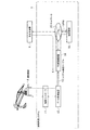
本発明の一実施形態として、インフラ設備等で使用する運搬機器Aの稼動状態を遠隔で監視する遠隔監視システムの構成について、図1を参照して説明する。本実施形態による遠隔監視システム1は、監視対象の運搬機器Aに接続された機器コントローラ11と、機器コントローラ11と双方向通信により接続されたデータ取得装置12と、データ取得装置12とシリアル通信ケーブル13で接続された外部接続装置14と、運搬機器Aから遠隔に設置され、外部接続装置14にネットワーク15を介して接続された監視装置16とを備える。
As an embodiment of the present invention, the configuration of a remote monitoring system that remotely monitors the operating state of a transporting device A used in infrastructure facilities or the like will be described with reference to FIG. The remote monitoring system 1 according to the present embodiment includes a
本実施形態において、遠隔監視システム1を構成する機器コントローラ11、データ取得装置12、外部接続装置14、監視装置16には、汎用のパーソナルコンピュータ等が用いられ、これらの装置は、外部機器と双方向通信を行う機能を有している。また、データ取得装置12および外部接続装置14は外部機器とシリアル通信を行うためのシリアルポートを有している。また、外部接続装置14と監視装置16とを接続するネットワーク15は、汎用の技術、例えばTCP/IPプロトコル等を用いたネットワークである。また、外部接続装置14と監視装置16との間は、ネットワーク15を利用したVPN(Virtual Private Network)で接続されている。
In the present embodiment, a general-purpose personal computer or the like is used for the
機器コントローラ11は、外部からの指示や予め設定された情報等に基づいて、運搬機器Aの動作(機器のON/OFF切替、運転速度や方向等)を制御するとともに、その稼動状態に関するデータ(以下、「稼働データ」と称する)を取得する。データ取得装置12は、機器コントローラ11と双方向通信可能な状態で接続され、機器コントローラ11で取得された運搬機器Aの稼動データを所定時間間隔で取得する。シリアル通信ケーブル13は、汎用のシリアル通信用のクロスケーブルの片側通信方向のケーブルが遮断されて、データ取得装置12から外部接続装置14への一方向の通信のみが確立され、外部接続装置14からデータ取得装置12への方向の通信は遮断されるように、データ取得装置12および外部接続装置14にシリアル通信接続される。外部接続装置14は、データ取得装置12からシリアル通信ケーブル13を介して運搬機器Aの稼動データを受信し、ネットワーク15のVPNを介して監視装置16に送信する。監視装置16は、外部接続装置14から送信された運搬機器の稼動データを受信して保持し、出力する。
The
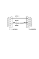
このように構成される遠隔監視システム1において利用されるシリアル通信ケーブル13について説明する。本実施形態によるシリアル通信ケーブル13には、汎用のシリアル通信用クロスケーブルが用いられ、図2に示すように、当該クロスケーブル内において所定方向へのデータ伝送に用いる信号線L1と、これとは逆方向へのデータ伝送に用いる信号線L2とのうち、いずれか一方のみを通信可能な状態にし、他方を通信不能にして、データ取得装置12と外部接続装置14とに接続させる。具体的には、通信不能にする方向の信号線を切断するかまたは、データ取得装置12または外部接続装置14の少なくともいずれか一方のシリアルポートに接続しないようにする。その際、データ取得装置12から外部接続装置14への方向への通信が可能になるように接続させる。
The serial communication cable 13 used in the remote monitoring system 1 configured as described above will be described. As the serial communication cable 13 according to the present embodiment, a general-purpose serial communication cross cable is used. As shown in FIG. 2, the signal line L1 used for data transmission in a predetermined direction in the cross cable, Only one of the signal lines L2 used for data transmission in the reverse direction is in a communicable state, the other is incapable of communication, and is connected to the
図2においては、信号線L2を切断し、信号線L1を、データ取得装置12から外部接続装置14にデータが伝送されるように接続させている。このようにクロスケーブルを接続させることで、データ取得装置12から外部接続装置14への通信は可能にしつつ、外部接続装置14からデータ取得装置12への通信は物理的に完全に遮断される。
In FIG. 2, the signal line L <b> 2 is disconnected and the signal line L <b> 1 is connected so that data is transmitted from the
この遠隔監視システム1では、機器コントローラ11で取得された運搬機器Aの稼動データが、データ取得装置12において所定時間間隔で取得される。そして、データ取得装置12で取得された稼動データが、シリアル通信ケーブル13を介してデータ取得装置12から外部接続装置14に送信される。外部接続装置14で受信された稼動データはさらに、ネットワーク15を利用したVPNを介して監視装置16に送信され、監視装置16においてモニタ等への出力や、稼働状態の正常/異常の判定等の処理に用いられる。
In the remote monitoring system 1, the operation data of the transport device A acquired by the
この遠隔監視システム1は、データ取得装置12と外部接続装置14との間が、物理的にデータ取得装置12から外部接続装置14への一方向にしか通信できない状態で構成されるため、たとえ外部の第三者装置XによりVPNのセキュリティが突破され外部接続装置14にアクセスされたとしても、外部接続装置14からデータ取得装置12へのアクセスは不可能であり、第三者装置Xから運搬機器Aの不適切な運転操作やデータの改ざん等が行われる可能性がなくなる。そのため、当該遠隔監視システムは、高い安全性および信頼性を保持することができる。
This remote monitoring system 1 is configured in a state in which the
以上の本実施形態によれば、汎用の装置やケーブル、および汎用の技術を用いたネットワークを利用することにより、安全性および信頼性が高く、安価な遠隔監視システムを簡易に構成することができる。 According to the present embodiment described above, by using a general-purpose device, a cable, and a network using a general-purpose technology, it is possible to easily configure an inexpensive remote monitoring system with high safety and reliability. .
上述した実施形態においては、データ取得装置12および外部接続装置14がシリアルポートを有する装置である場合について説明したが、シリアルポートを有さない装置を用いる場合について、図3を参照して説明する。
In the embodiment described above, the case where the
図3に示す遠隔監視システム2では、機器コントローラ11に接続されるデータ取得装置17および、監視装置16にネットワーク15を介して接続される外部接続装置18として、シリアルポートを有さず、USBポートを有する汎用のパーソナルコンピュータ等が用いられている。
In the remote monitoring system 2 shown in FIG. 3, the
この場合、データ取得装置17のUSBポートにシリアル通信変換器19を接続させるとともに、外部接続装置18のUSBポートにシリアル通信変換器20を接続させ、これらシリアル通信変換器19と20との間を、シリアル通信ケーブル13で接続させる。ここで使用するシリアル通信ケーブル13は、上述した遠隔監視システム1で使用したシリアル通信ケーブル13と同様に一方向にのみ通信可能な状態に構成されたものであり、データ取得装置17側のシリアル通信変換器19から外部接続装置18側のシリアル通信変換器20への通信が可能で、逆向きの通信(外部接続装置18側からデータ取得装置17側への通信)が遮断されるように接続されている。
In this case, the
このように構成することにより、データ取得装置および外部接続装置にシリアルポートを有さないパーソナルコンピュータを用いた遠隔監視システム2においても、上述した遠隔監視システム1と同様に、安全性および信頼性が高く、安価な遠隔監視システムを簡易に構成することができる。 With this configuration, in the remote monitoring system 2 using a personal computer that does not have a serial port in the data acquisition device and the external connection device, similarly to the remote monitoring system 1 described above, safety and reliability are ensured. A high-priced and inexpensive remote monitoring system can be easily configured.
1、2 遠隔監視システム
11 機器コントローラ
12、17 データ取得装置
13 シリアル通信ケーブル
14、18 外部接続装置
15 ネットワーク
16 監視装置
19、20 シリアル通信変換器
1, 2
Claims (2)
双方向通信機能を有し、前記機器の稼動状態を示すデータを監視する監視装置と、
双方向通信機能を有し、前記データ取得装置から前記機器の稼動状態を示すデータを受信して、ネットワークを介して前記監視装置に送信する外部接続装置と、
を備えた遠隔監視システムにおいて、
前記データ取得装置と前記外部接続装置との間が、シリアル通信用のクロスケーブルの片側通信方向の信号線が遮断された状態で、前記データ取得装置から前記外部接続装置への一方向通信のみが可能になるように接続される
ことを特徴とする遠隔監視システム。 A data acquisition device that has a bidirectional communication function and acquires data indicating the operating state of the monitored device;
A monitoring device having a bidirectional communication function and monitoring data indicating the operating state of the device;
An external connection device having a bidirectional communication function, receiving data indicating an operating state of the device from the data acquisition device, and transmitting the data to the monitoring device via a network;
In the remote monitoring system with
Only one-way communication from the data acquisition device to the external connection device is possible between the data acquisition device and the external connection device in a state where the signal line in the one-side communication direction of the cross cable for serial communication is cut off. A remote monitoring system characterized by being connected as possible.
ことを特徴とする請求項1に記載の遠隔監視システム。 Between the serial communication converter connected to the data acquisition device and the serial communication converter connected to the external connection device, the signal line in the one-side communication direction of the cross cable for serial communication is cut off. The remote monitoring system according to claim 1, wherein the remote acquisition system is connected so that only one-way communication from the data acquisition device to the external connection device is possible.
Priority Applications (1)
| Application Number | Priority Date | Filing Date | Title |
|---|---|---|---|
| JP2016084156A JP2017194810A (en) | 2016-04-20 | 2016-04-20 | Remote monitoring system |
Applications Claiming Priority (1)
| Application Number | Priority Date | Filing Date | Title |
|---|---|---|---|
| JP2016084156A JP2017194810A (en) | 2016-04-20 | 2016-04-20 | Remote monitoring system |
Publications (1)
| Publication Number | Publication Date |
|---|---|
| JP2017194810A true JP2017194810A (en) | 2017-10-26 |
Family
ID=60154799
Family Applications (1)
| Application Number | Title | Priority Date | Filing Date |
|---|---|---|---|
| JP2016084156A Pending JP2017194810A (en) | 2016-04-20 | 2016-04-20 | Remote monitoring system |
Country Status (1)
| Country | Link |
|---|---|
| JP (1) | JP2017194810A (en) |
Citations (4)
| Publication number | Priority date | Publication date | Assignee | Title |
|---|---|---|---|---|
| JP2002232505A (en) * | 2001-01-31 | 2002-08-16 | Toshiba Corp | Communication system and program thereof |
| JP2003018308A (en) * | 2001-06-29 | 2003-01-17 | Hitachi Electronics Service Co Ltd | Method for monitoring user system, and remote monitoring system |
| JP2011021977A (en) * | 2009-07-15 | 2011-02-03 | Hitachi Ltd | System for monitoring of nuclear power generation plant, and operation-maintenance data management system |
| US20150365346A1 (en) * | 2014-06-11 | 2015-12-17 | Electronics And Telecommunications Research Institute | Apparatus and method for multilateral one-way communication |
-
2016
- 2016-04-20 JP JP2016084156A patent/JP2017194810A/en active Pending
Patent Citations (4)
| Publication number | Priority date | Publication date | Assignee | Title |
|---|---|---|---|---|
| JP2002232505A (en) * | 2001-01-31 | 2002-08-16 | Toshiba Corp | Communication system and program thereof |
| JP2003018308A (en) * | 2001-06-29 | 2003-01-17 | Hitachi Electronics Service Co Ltd | Method for monitoring user system, and remote monitoring system |
| JP2011021977A (en) * | 2009-07-15 | 2011-02-03 | Hitachi Ltd | System for monitoring of nuclear power generation plant, and operation-maintenance data management system |
| US20150365346A1 (en) * | 2014-06-11 | 2015-12-17 | Electronics And Telecommunications Research Institute | Apparatus and method for multilateral one-way communication |
Similar Documents
| Publication | Publication Date | Title |
|---|---|---|
| US9282102B2 (en) | Secure front-end interface | |
| CA2813983C (en) | System and method to protect against local control failure using cloud-hosted control system back-up processing | |
| US9419975B2 (en) | Bi-directional communication over a one-way link | |
| JP2014146087A (en) | Monitoring control system | |
| US11601472B2 (en) | One-way transfer device with secure reverse channel | |
| KR101252529B1 (en) | The security system of a soft redundancy sub-station | |
| JP6968175B2 (en) | Security devices and fieldbus systems to support secure communication over the fieldbus | |
| ES2751098T3 (en) | Network coupling equipment and transmission procedure for packet-based data networks in process control systems or operation control systems | |
| US9413717B2 (en) | Apparatus and method for connecting computer networks | |
| JP5836528B1 (en) | Communication connection device and communication system | |
| KR101889502B1 (en) | Abnormal traffic detection method on control system protocol | |
| EP3377973B1 (en) | Improvements in and relating to communication links | |
| JP2017194810A (en) | Remote monitoring system | |
| CN106375273A (en) | Automated network and method for monitoring data packet transmission security | |
| US20250273914A1 (en) | Plug connector housing having a data diode for electronic data lines | |
| CA2878142C (en) | Method and control arrangement to secure an alarm system | |
| KR101069170B1 (en) | Fault management system for intelligent network switching device | |
| KR20240047239A (en) | Data transmission apparatus based on physical network separation | |
| JP2010199943A (en) | Unidirectional data communication method and information processor | |
| CN115412402A (en) | Communication gateway | |
| US20240195755A1 (en) | Network Tapped Data Diode | |
| KR101813687B1 (en) | Monitoring system and method using wireless communications | |
| JP2016129346A (en) | Supervisory control system | |
| KR101179528B1 (en) | Direct Digital Controller having convertible transmission line and Management system having the same | |
| JP2008242951A (en) | Monitoring system for digital protection relay |
Legal Events
| Date | Code | Title | Description |
|---|---|---|---|
| A621 | Written request for application examination |
Free format text: JAPANESE INTERMEDIATE CODE: A621 Effective date: 20190201 |
|
| A977 | Report on retrieval |
Free format text: JAPANESE INTERMEDIATE CODE: A971007 Effective date: 20191212 |
|
| A131 | Notification of reasons for refusal |
Free format text: JAPANESE INTERMEDIATE CODE: A131 Effective date: 20200107 |
|
| A521 | Request for written amendment filed |
Free format text: JAPANESE INTERMEDIATE CODE: A523 Effective date: 20200227 |
|
| A131 | Notification of reasons for refusal |
Free format text: JAPANESE INTERMEDIATE CODE: A131 Effective date: 20200519 |
|
| A02 | Decision of refusal |
Free format text: JAPANESE INTERMEDIATE CODE: A02 Effective date: 20201006 |