JP2017194811A - Frequency characteristic analysis apparatus, method, and program - Google Patents
Frequency characteristic analysis apparatus, method, and program Download PDFInfo
- Publication number
- JP2017194811A JP2017194811A JP2016084172A JP2016084172A JP2017194811A JP 2017194811 A JP2017194811 A JP 2017194811A JP 2016084172 A JP2016084172 A JP 2016084172A JP 2016084172 A JP2016084172 A JP 2016084172A JP 2017194811 A JP2017194811 A JP 2017194811A
- Authority
- JP
- Japan
- Prior art keywords
- calculation
- ordering
- unit
- decomposition
- circuit
- Prior art date
- Legal status (The legal status is an assumption and is not a legal conclusion. Google has not performed a legal analysis and makes no representation as to the accuracy of the status listed.)
- Granted
Links
Images


Classifications
-
- Y—GENERAL TAGGING OF NEW TECHNOLOGICAL DEVELOPMENTS; GENERAL TAGGING OF CROSS-SECTIONAL TECHNOLOGIES SPANNING OVER SEVERAL SECTIONS OF THE IPC; TECHNICAL SUBJECTS COVERED BY FORMER USPC CROSS-REFERENCE ART COLLECTIONS [XRACs] AND DIGESTS
- Y02—TECHNOLOGIES OR APPLICATIONS FOR MITIGATION OR ADAPTATION AGAINST CLIMATE CHANGE
- Y02E—REDUCTION OF GREENHOUSE GAS [GHG] EMISSIONS, RELATED TO ENERGY GENERATION, TRANSMISSION OR DISTRIBUTION
- Y02E60/00—Enabling technologies; Technologies with a potential or indirect contribution to GHG emissions mitigation
Landscapes
- Complex Calculations (AREA)
Abstract
【課題】計算精度を維持しつつ周波数特性計算に要する時間を大幅に短縮することが可能な周波数特性解析装置、方法、及びプログラムを提供する。【解決手段】周波数特性解析装置1は、計算周波数に応じた解析対象の回路方程式を、疎行列を用いて作成する回路方程式作成部14aと、回路方程式作成部14aで作成される回路方程式のうち、特定の場合に作成された回路方程式の疎行列に対してのみ完全ピボッティングによる順序付けを行う順序付け部14bと、順序付け部14bで直近に行われた順序付け結果を用いて疎行列のLU分解を行うLU分解部14cと、LU分解部14cでLU分解された行列を用いて求解演算を行う求解演算部14eと、を備える。【選択図】図1A frequency characteristic analysis apparatus, method, and program capable of significantly reducing the time required for frequency characteristic calculation while maintaining calculation accuracy are provided. A frequency characteristic analyzing apparatus 1 generates a circuit equation to be analyzed according to a calculation frequency using a sparse matrix, and a circuit equation created by a circuit equation creating unit 14a. An ordering unit 14b that performs ordering by complete pivoting only on a sparse matrix of a circuit equation created in a specific case, and an LU that performs LU decomposition of the sparse matrix using the ordering result most recently performed by the ordering unit 14b A decomposition unit 14c, and a solution calculation unit 14e that performs a solution calculation using the matrix subjected to LU decomposition by the LU decomposition unit 14c. [Selection] Figure 1
Description
本発明は、周波数特性解析装置、方法、及びプログラムに係り、特に電力系統の周波数特性解析等に適用して有用な周波数特性解析装置、方法、及びプログラムに関する。 The present invention relates to a frequency characteristic analysis apparatus, method, and program, and more particularly to a frequency characteristic analysis apparatus, method, and program that are useful when applied to frequency characteristic analysis of a power system.
電力系統で発生する過電圧や過電流の解析、電力品質の解析、交直変換器の動特性の解析等には、電力及び電流の時間変化を波形レベルで解析可能な瞬時値解析が有効である。このような瞬時値解析が可能な瞬時値解析プログラムの多くには、特定の母線から系統を見込んだインピーダンスの周波数特性を計算する機能があり、直流送電設備や周波数変換設備の交直変換器と交流系統の相互作用によって発生する高調波不安定現象や高調波特性を含めた過渡過電圧の解析等で用いられる。 For analysis of overvoltage and overcurrent generated in a power system, analysis of power quality, analysis of dynamic characteristics of an AC / DC converter, instantaneous value analysis capable of analyzing temporal changes in power and current at a waveform level is effective. Many of the instantaneous value analysis programs that can perform such instantaneous value analysis have a function to calculate the frequency characteristics of impedance from the specified bus, and the AC / DC converter of the DC power transmission equipment and frequency conversion equipment and AC It is used for analysis of transient overvoltage including harmonic instability and harmonic characteristics generated by system interaction.
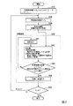
図12は、従来の周波数特性計算の計算過程を示すフローチャートである。図12に示す通り、周波数特性計算は、通常、回路の交流定常解を求める計算(交流定常解計算)を、周波数を変化させながら繰り返し実行する計算である。交流定常解計算は、連立一次方程式となる回路方程式を作成する定式化過程と、作成された回路方程式を解く求解過程とからなる。 FIG. 12 is a flowchart showing a calculation process of conventional frequency characteristic calculation. As shown in FIG. 12, the frequency characteristic calculation is usually a calculation that repeatedly executes a calculation for obtaining an AC steady solution of the circuit (AC steady solution calculation) while changing the frequency. The AC steady solution calculation includes a formulation process for creating a circuit equation that is a simultaneous linear equation and a solution process for solving the created circuit equation.
定式化過程は、回路中の全ノードと全回路部品の情報から回路方程式を作成する過程である。例えば、回路にNn個の独立ノード、Nb個の回路部品(ブランチ)が存在すると仮定した場合、回路中のNn個のノードの電圧からなるベクトルu、Nb個の回路部品を流れる電流からなるベクトルi、Nb個の回路部品の両端電圧からなるベクトルvを未知変数として取り扱い、その回路方程式は以下の(1)式となる。
上記(1)式をスパースタブロー方程式と呼び、Fをタブロー行列と呼ぶ。上記(1)式中のF,x,yは、以下の(2)式で表される。
ここで、Aは、回路中のNn個の独立ノードとNb個のブランチの接続状態を関連付けるNb×Nnのブランチ対ノード接続行列である。Iは、Nb×Nbの単位行列である。B=[B1 −B2]は、各ブランチのブランチ電圧vとブランチ電流iとを関連付けるNb×2Nbのブランチ特性行列である。sは、回路中の電圧源、電流源の値により定まるベクトルである。N=Nn×2Nbのとき、x,yは要素数がN個のベクトルとなり、FはN×Nの行列となる。交流定常解計算では、ここで示したスパースタブロー方程式の全ての量は複素数となる。 Here, A is an N b × N n branch-to-node connection matrix that associates connection states of N n independent nodes and N b branches in the circuit. I is a unit matrix of N b × N b . B = [B 1 −B 2 ] is a branch characteristic matrix of N b × 2N b that associates the branch voltage v and the branch current i of each branch. s is a vector determined by the values of the voltage source and current source in the circuit. When N = N n × 2N b , x and y are vectors having N elements, and F is an N × N matrix. In the AC steady solution calculation, all the quantities of the Spasterblow equation shown here are complex numbers.
ブランチ特性行列Bは、ブランチ特性方程式から得られる。周波数をf=ω/(2π)としたとき、例えばインダクタL、キャパシタCのブランチ特性方程式はそれぞれ、以下の(3)式及び(4)式で表される。 The branch characteristic matrix B is obtained from the branch characteristic equation. When the frequency is f = ω / (2π), for example, the branch characteristic equations of the inductor L and the capacitor C are expressed by the following equations (3) and (4), respectively.
但し、iL,iCは、L,Cに流れる電流(ブランチ電流)であり、vL,vCは、L,Cの両端電圧(ブランチ電圧)である。Lがb番目のブランチだった場合、B及びsのb行目は、以下の(5)式で表される。
但し、上記(5)式左辺の「|」印より左は行列B1のb行目を示し、「|」印より右は行列−B2のb行目を示し、右辺はsのb行目を示す。また、上記(5)式下部の2つの矢印は、1と−1/jωLがそれぞれB1とB2のb列目であることを示し、「…」で省略された要素は0である。尚、解析回路中に非線形素子が配置された場合には、非線形素子を無視するか、或いは原点近くの特性で線形化して取り扱う。また、回路中の電圧源、電流源の値により定まるベクトルsは、電圧源が発生する電圧波形がEmcos(ωt+θ)のとき、sの該当する要素にEmejθを代入する。Imcos(ωt+θ)を発生する電流源については、Imejθを代入する。 However, the left side from the “|” mark on the left side of equation (5) indicates the b-th row of the matrix B 1 , the right side from the “|” mark indicates the b-th row of the matrix −B 2 , and the right side is the b row of s. Showing eyes. The two arrows at the bottom of the above equation (5) indicate that 1 and −1 / jωL are the b-th columns of B 1 and B 2 , respectively, and the elements omitted by “...” Are 0. If a nonlinear element is arranged in the analysis circuit, the nonlinear element is ignored or handled by linearizing with characteristics near the origin. The vector s determined by the values of the voltage source and the current source in the circuit substitutes E m e jθ for the corresponding element of s when the voltage waveform generated by the voltage source is E m cos (ωt + θ). For a current source that generates I m cos (ωt + θ), I m e jθ is substituted.
求解過程は、順序付け、LU分解、前進・後退代入と呼ばれる処理が順番に実行される。順序付けは、計算精度の向上を目的に行列要素を並べ替える操作である。例えば、以下に示す手順で行列要素の並べ替えが行われる。
(イ)行列Fについて、各行に存在する非零要素数NRと、各列に存在する非零要素数NCとを求める。
(ロ)NRC=(NR−1)×(NC−1)を要素毎に計算し、NRCが最も小さい要素を1行目の対角要素(ピボット)となるように入れ替え操作を行う。NRCが同じ要素が複数ある場合は、最も絶対値が大きい要素を選択する。
(ハ)1行1列を除いた残りの行列(部分行列)をFとして考え、(イ)〜(ハ)の手順を最後の行まで繰り返し行う。
In the solution process, processes called ordering, LU decomposition, and forward / backward substitution are executed in order. Ordering is an operation of rearranging matrix elements for the purpose of improving calculation accuracy. For example, the matrix elements are rearranged in the following procedure.
(A) For the matrix F, the number of non-zero elements NR present in each row and the number of non-zero elements NC present in each column are obtained.
(B) NRC = (NR−1) × (NC−1) is calculated for each element, and the element with the smallest NRC is replaced so as to be the diagonal element (pivot) in the first row. When there are a plurality of elements having the same NRC, the element having the largest absolute value is selected.
(C) The remaining matrix (submatrix) excluding 1 row and 1 column is considered as F, and the procedures (a) to (c) are repeated until the last row.
ここで、手順(ロ)は、NRCが最も小さい要素(NRCが同じ場合は絶対値が大きい要素)を選び出し、それを対角要素にする作業であるが、例えばi行目の対角要素の探索において、その探索対象をi行の要素のみとした場合と、既に対角要素を決定した行と列を除く全ての要素とした場合の2通りの手法が考えられる。前者は部分ピボッティング、後者は完全ピボッティングと呼ばれている。一般に、部分ピボッティングは、探索範囲が狭いため計算量は少なく、完全ピボッティングは、探索範囲が広いため計算量は大きいが、より最適な対角要素を選び出すことができるため計算精度は高くなる。 Here, the procedure (b) is an operation for selecting an element having the smallest NRC (an element having a large absolute value when NRC is the same) and making it a diagonal element. In the search, two methods can be considered, in which the search target is only the i-row element and all elements except the row and column for which the diagonal elements have already been determined. The former is called partial pivoting, and the latter is called full pivoting. In general, partial pivoting requires a small amount of calculation because the search range is narrow, and complete pivoting requires a large amount of calculation because the search range is wide, but the calculation accuracy is high because a more optimal diagonal element can be selected.
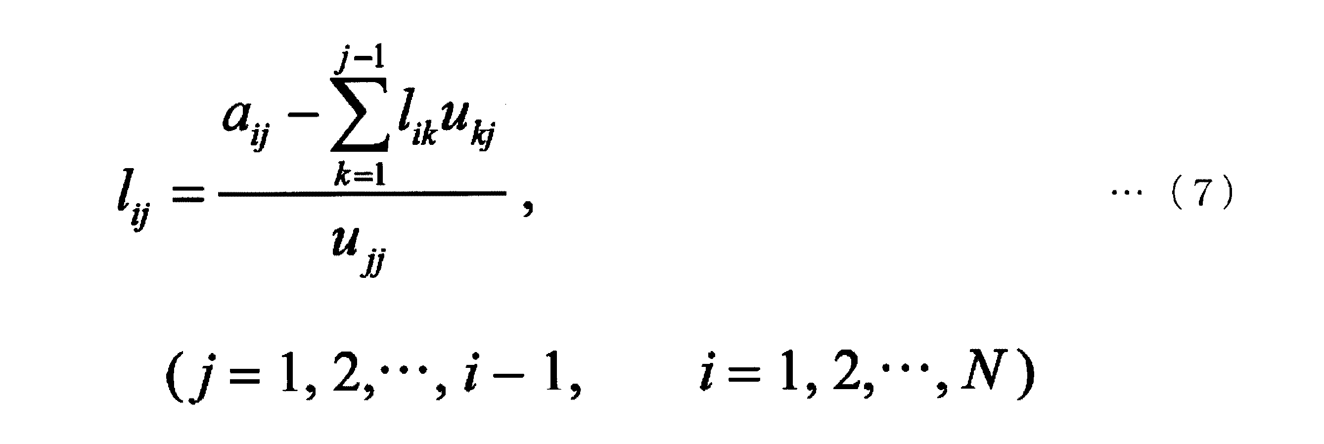
LU分解及び前進・後退代入は、回路方程式の係数行列(上記(1)式中のタブロー行列F)を、下三角行列Lと上三角行列Uとに分解し、前進代入及び後退代入と呼ばれる操作によって未知数となるxを求める操作である。いま、上記(1)式の行列要素をaij(但し、1番目の添え字は行番号、2番目の添え字は列番号、i=1,2,…,N、j=1,2,…,N)としたとき、FのLU分解後の下三角行列Lの要素lijと上三角行列Uの要素uijはそれぞれ以下の(6)式及び(7)式により計算することができる。 LU decomposition and forward / backward substitution are operations called forward substitution and backward substitution by decomposing a coefficient matrix (tableau matrix F in the above equation (1)) into a lower triangular matrix L and an upper triangular matrix U. Is an operation for obtaining x which is an unknown. Now, the matrix element of the above equation (1) is a ij (where the first subscript is the row number, the second subscript is the column number, i = 1, 2,..., N, j = 1, 2, .., N), the element l ij of the lower triangular matrix L after the LU decomposition of F and the element u ij of the upper triangular matrix U can be calculated by the following equations (6) and (7), respectively. .
次に、求めたuij,lijを用いた前進・後退代入によりxを求める。尚、LU分解に続く前進・後退代入の過程の詳細な説明は省略する。xを得ることにより、交流定常解として前述したノード電圧、ブランチ電流、ブランチ電圧が求められる。以上説明した一連の過程(定式化、求解)を、計算周波数fを更新して繰り返し行うことで、回路の周波数特性を求めることができる。尚、以下の非特許文献1,2には、周波数特性計算に係るものではないが、電圧及び電流の時間変化を求める通常の瞬時値解析における計算時間の短縮を図る方法が開示されている。
Next, x is obtained by forward / backward substitution using the obtained u ij and l ij . A detailed description of the forward / backward substitution process following the LU decomposition will be omitted. By obtaining x, the above-mentioned node voltage, branch current, and branch voltage are obtained as an AC steady solution. The frequency characteristics of the circuit can be obtained by repeatedly performing the series of processes (formulation and solution) described above by updating the calculation frequency f. The following
ところで、上述したLU分解に基づく求解は、周波数特性計算で行われるだけでなく、電圧及び電流の時間変化を求める通常の瞬時値解析でも行われる。通常の瞬時値解析では、上記(1)式を各計算時間ステップで解く計算過程となるが、素子の値が時間によって変化する時変素子や非線形素子が回路中に存在しない場合には、上記(1)式で計算時間ステップごとに変化するのはyのみであり、Fは変化しない。即ち、通常の瞬時値解析では、Fに対する順序付け及びLU分解を最初に一度だけ行っておけば良く、各計算時間ステップの解xは、変化するyに対して前進代入及び後退代入を行うだけで求めることができる。 By the way, the solution based on the above-described LU decomposition is performed not only by the frequency characteristic calculation but also by the normal instantaneous value analysis for obtaining the time change of the voltage and current. Normal instantaneous value analysis is a calculation process in which the above equation (1) is solved at each calculation time step. However, when there is no time-varying element or nonlinear element in which the element value changes with time, In equation (1), only y changes for each calculation time step, and F does not change. That is, in the normal instantaneous value analysis, the ordering and LU decomposition for F need only be performed once at first, and the solution x of each calculation time step can be performed simply by performing forward substitution and backward substitution for changing y. Can be sought.
しかしながら、周波数特性計算においては、計算周波数fの更新によってブランチ特性方程式が変化するため、設定された計算周波数f毎にFが変化してしまう。このため、周波数特性計算における求解過程では、通常の瞬時値解析における求解過程のように順序付け及びLU分解を省略することはできず、計算周波数f毎に順序付け及びLU分解を実行する必要がある。このように、周波数特性計算では、瞬時値解析の場合とは異なり、求解過程により多くの時間を要し、その計算時間の短縮が課題となっている。 However, in the frequency characteristic calculation, the branch characteristic equation changes by updating the calculation frequency f, so that F changes for each set calculation frequency f. For this reason, in the solution process in the frequency characteristic calculation, ordering and LU decomposition cannot be omitted as in the solution process in normal instantaneous value analysis, and it is necessary to execute ordering and LU decomposition for each calculation frequency f. As described above, in the frequency characteristic calculation, unlike the case of the instantaneous value analysis, more time is required for the solution-finding process, and the reduction of the calculation time is a problem.
ここで、前述の通り、求解過程における順序付けでは、部分ピボッティング又は完全ピボッティングを用いることができる。周波数特性計算における求解過程の計算時間を短縮するには、完全ピボッティングよりも計算時間が少ない部分ピボッティングを用いれば良いとも考えられる。部分ピボッティングは、計算精度は原理的に完全ピボッティングより劣るものの、多くの場合で解析精度の低下は問題とならないが、部分ピボッティングで計算精度に問題を生じる例が報告されており、必ずしも万能の手法とはいえない。そこで、計算精度の維持の観点から完全ピボッティングを用いつつ、求解過程の計算時間を短縮する必要がある。 Here, as described above, partial pivoting or complete pivoting can be used for ordering in the solution process. In order to shorten the calculation time of the solution process in the frequency characteristic calculation, it may be considered to use partial pivoting which requires less calculation time than complete pivoting. Partial pivoting is theoretically inferior to perfect pivoting in principle, but in many cases, the degradation of analysis accuracy is not a problem. That's not true. Therefore, it is necessary to reduce the calculation time of the solution process while using complete pivoting from the viewpoint of maintaining calculation accuracy.
本発明は上記事情に鑑みてなされたものであり、計算精度を維持しつつ周波数特性計算に要する時間を大幅に短縮することが可能な周波数特性解析装置、方法、及びプログラムを提供することを目的とする。 The present invention has been made in view of the above circumstances, and an object thereof is to provide a frequency characteristic analysis apparatus, method, and program capable of significantly reducing the time required for frequency characteristic calculation while maintaining calculation accuracy. And
上記課題を解決するために、本発明の周波数特性解析装置(1)は、計算周波数に応じた解析対象の回路方程式を、疎行列を用いて作成する回路方程式作成部(14a)と、前記回路方程式作成部で作成される回路方程式のうち、特定の場合に作成された回路方程式の前記疎行列に対してのみ完全ピボッティングによる順序付けを行う順序付け部(14b)と、前記順序付け部で直近に行われた順序付け結果を用いて前記疎行列のLU分解を行うLU分解部(14c)と、前記LU分解部でLU分解された行列を用いて求解演算を行う求解演算部(14e)と、を備える。
また、本発明の周波数特性解析装置は、前記順序付け部が、前記回路方程式作成部で最初に回路方程式が作成された場合に、前記完全ピボッティングによる順序付けを行う。
また、本発明の周波数特性解析装置は、前記LU分解部でLU分解された行列を用いて計算精度を評価する計算精度評価部(14d)を更に備えており、前記順序付け部が、計算精度評価部で計算精度の悪化が生じたと評価された場合に、前記完全ピボッティングによる順序付けを行う。
また、本発明の周波数特性解析装置は、前記計算精度評価部が、前記LU分解部でLU分解された行列を用いて計算精度の指標を示す不安定因子(ρ)を求め、該不安定因子が予め規定された閾値(ρth)を超えた場合に、計算精度の悪化が生じたと評価する。
本発明の周波数特性解析方法は、計算周波数に応じた解析対象の回路方程式を、疎行列を用いて作成する第1ステップ(S30)と、前記第1ステップで作成される回路方程式のうち、特定の場合に作成された回路方程式の前記疎行列に対してのみ完全ピボッティングによる順序付けを行う第2ステップ(S41)と、前記第2ステップで直近に行われた順序付け結果を用いて前記疎行列のLU分解を行う第3ステップ(S42)と、前記第3ステップでLU分解された行列を用いて求解演算を行う第4ステップ(S44)と、前記計算周波数を変えて前記第1ステップから第4ステップを繰り返す第5ステップ(S20)と、を有する。
また、本発明の周波数特性解析方法は、前記第3ステップでLU分解された行列を用いて計算精度を評価する第6ステップ(S43)を更に有しており、前記第2ステップが、前記第1ステップで最初に回路方程式が作成された場合、或いは前記第6ステップで計算精度の悪化が生じたと評価された場合に、前記完全ピボッティングによる順序付けを行う。
本発明の周波数特性解析プログラムは、コンピュータを、計算周波数に応じた解析対象の回路方程式を、疎行列を用いて作成する回路方程式作成手段(14a)と、前記回路方程式作成手段で作成される回路方程式のうち、特定の場合に作成された回路方程式の前記疎行列に対してのみ完全ピボッティングによる順序付けを行う順序付け手段(14b)と、前記順序付け手段で直近に行われた順序付け結果を用いて前記疎行列のLU分解を行うLU分解手段(14c)と、前記LU分解手段でLU分解された行列を用いて求解演算を行う求解演算手段(14e)と、して機能させる。
また、本発明の周波数特性解析プログラムは、前記コンピュータを、前記LU分解手段でLU分解された行列を用いて計算精度を評価する計算精度評価手段(14d)として更に機能させ、前記順序付け手段が、前記回路方程式作成手段で最初に回路方程式が作成された場合、或いは前記計算精度評価手段で計算精度の悪化が生じたと評価された場合に、前記完全ピボッティングによる順序付けを行う。
In order to solve the above problems, a frequency characteristic analyzing apparatus (1) of the present invention includes a circuit equation creating unit (14a) that creates a circuit equation to be analyzed according to a calculation frequency using a sparse matrix, and the circuit Of the circuit equations created by the equation creation unit, an ordering unit (14b) that performs ordering by complete pivoting only on the sparse matrix of the circuit equation created in a specific case, and the ordering unit that is most recently performed An LU decomposition unit (14c) that performs LU decomposition of the sparse matrix using the ordered result, and a solution calculation operation unit (14e) that performs solution calculation using the matrix subjected to LU decomposition by the LU decomposition unit.
In the frequency characteristic analyzing apparatus of the present invention, the ordering unit performs the ordering by the complete pivoting when the circuit equation is first created by the circuit equation creating unit.
The frequency characteristic analysis apparatus of the present invention further includes a calculation accuracy evaluation unit (14d) that evaluates calculation accuracy using the matrix subjected to LU decomposition by the LU decomposition unit, and the ordering unit includes a calculation accuracy evaluation. When it is evaluated that the calculation accuracy has deteriorated in the section, the ordering is performed by the complete pivoting.
Further, in the frequency characteristic analyzing apparatus of the present invention, the calculation accuracy evaluation unit obtains an unstable factor (ρ) indicating an index of calculation accuracy using a matrix subjected to LU decomposition by the LU decomposition unit, and the unstable factor When the value exceeds a predetermined threshold value (ρ th ), it is evaluated that the calculation accuracy has deteriorated.
The frequency characteristic analysis method according to the present invention includes a first step (S30) in which a circuit equation to be analyzed corresponding to a calculation frequency is created using a sparse matrix, and a specification among the circuit equations created in the first step. A second step (S41) for ordering by complete pivoting only for the sparse matrix of the circuit equation created in the case of (2), and using the ordering result most recently performed in the second step, the LU of the sparse matrix A third step (S42) for performing decomposition, a fourth step (S44) for performing a solution calculation using the matrix subjected to LU decomposition in the third step, and the first to fourth steps by changing the calculation frequency. The fifth step (S20) is repeated.
The frequency characteristic analysis method of the present invention further includes a sixth step (S43) for evaluating calculation accuracy using the matrix subjected to LU decomposition in the third step, and the second step includes the first step. When the circuit equation is first created in one step, or when it is evaluated that the calculation accuracy is deteriorated in the sixth step, the ordering by the complete pivoting is performed.
The frequency characteristic analysis program of the present invention is a circuit created by a circuit equation creating means (14a) for creating a circuit equation to be analyzed according to a calculation frequency using a sparse matrix, and a circuit created by the circuit equation creating means. Among the equations, the ordering means (14b) for performing ordering by complete pivoting only on the sparse matrix of the circuit equation created in a specific case, and the sparseness using the ordering result most recently performed by the ordering means. An LU decomposition means (14c) that performs LU decomposition of a matrix and a solution calculation operation means (14e) that performs solution calculation using the matrix subjected to LU decomposition by the LU decomposition means function.
The frequency characteristic analysis program according to the present invention further causes the computer to function as a calculation accuracy evaluation unit (14d) that evaluates calculation accuracy using a matrix subjected to LU decomposition by the LU decomposition unit, and the ordering unit includes: When the circuit equation is first created by the circuit equation creating unit, or when it is evaluated that the calculation accuracy has been deteriorated by the calculation accuracy evaluating unit, the ordering by the complete pivoting is performed.
本発明によれば、疎行列を用いて計算周波数に応じた解析対象の回路方程式を作成し、作成された回路方程式のうち、特定の場合に作成された回路方程式の疎行列に対してのみ完全ピボッティングによる順序付けを行い、直近に行われた順序付け結果を用いて疎行列のLU分解を行い、LU分解された行列を用いて求解演算を行うようにしている。これにより、特定の場合以外における完全ピボッティングによる順序付けを省略することができることから、計算精度を維持しつつ周波数特性計算に要する時間を大幅に短縮することが可能であるという効果がある。 According to the present invention, a circuit equation to be analyzed corresponding to a calculation frequency is created using a sparse matrix, and only a sparse matrix of a circuit equation created in a specific case among the created circuit equations is complete. Ordering is performed by pivoting, LU decomposition of a sparse matrix is performed using the most recent ordering result, and solution calculation is performed using the LU decomposed matrix. As a result, since ordering by complete pivoting in cases other than a specific case can be omitted, there is an effect that the time required for frequency characteristic calculation can be greatly shortened while maintaining calculation accuracy.
以下、図面を参照して本発明の一実施形態による周波数特性解析装置、方法、及びプログラムについて詳細に説明する。尚、以下では、解析対象が電力系統である場合を例に挙げて説明するが、本発明は、解析対象が電力系統に限られる訳ではなく、任意の電気回路を解析対象とすることができる。 Hereinafter, a frequency characteristic analyzing apparatus, method, and program according to an embodiment of the present invention will be described in detail with reference to the drawings. In the following, the case where the analysis target is a power system will be described as an example, but the present invention is not limited to the power system, and any electric circuit can be the analysis target. .
〈周波数特性解析装置〉
図1は、本発明の一実施形態による周波数特性解析装置の要部構成を示すブロック図である。図1に示す通り、本実施形態の周波数特性解析装置1は、入力装置11、出力装置12、補助記憶装置13、及び演算処理装置14を備えており、解析対象としての電力系統の周波数特性計算を行う。このような周波数特性解析装置1は、例えばデスクトップ型のパーソナルコンピュータによって実現される。
<Frequency characteristics analyzer>
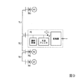
FIG. 1 is a block diagram showing a main configuration of a frequency characteristic analyzing apparatus according to an embodiment of the present invention. As shown in FIG. 1, the frequency
入力装置11は、例えばキーボードやポインティングデバイス等を備えており、周波数特性解析装置1を使用するユーザの操作に応じた指示を演算処理装置14に出力する。出力装置12は、例えば液晶表示装置やプリンタ等を備えており、演算処理装置14から出力される各種情報を出力する。補助記憶装置13は、例えばHDD(ハードディスクドライブ)やSSD(ソリッドステートドライブ)等を備えており、電力系統の解析を行う上で用いられる各種情報(順序付け結果OR及び評価パラメータPR:詳細は後述する)及び周波数特性解析プログラムPG等を記憶する。
The
演算処理装置14は、入力装置11から入力される操作指示に基づき、補助記憶装置13に記憶された周波数特性解析プログラムPGに従い補助記憶装置13に記憶された各種情報を用いて電力系統の周波数特性計算を行う。この演算処理装置14は、回路方程式作成部14a(回路方程式作成手段)、順序付け部14b(順序付け手段)、LU分解部14c(LU分解手段)、計算精度評価部14d(計算精度評価手段)、及び求解演算部14e(求解演算手段)を備える。
The
回路方程式作成部14aは、解析対象である電力系統の回路方程式を、疎行列を用いて作成する。具体的に、回路方程式作成部14aは、前述した(1)式に示されるスパースタブロー方程式を、計算周波数fに応じて作成する。尚、上記の疎行列は、前述した(2)式に示すタブロー行列Fである。解析対象である電力系統の構成が変わらない場合において、計算周波数fが変わると、前述した(2)式に示すタブロー行列F中のブランチ特性行列B=[B1 −B2]が変わる。
The circuit
順序付け部14bは、回路方程式作成部14aで作成される回路方程式のタブロー行列Fに対して、完全ピボッティングによる順序付けを行う。ここで、順序付け部14bは、回路方程式作成部14aで作成される回路方程式のうち、特定の場合に作成された回路方程式のタブロー行列Fに対してのみ完全ピボッティングによる順序付けを行う。これは、周波数特性解析に要する時間を短縮するためである。
The
具体的に、順序付け部14bは、回路方程式作成部14aで最初に回路方程式が作成された場合、或いは計算精度評価部14dで計算精度の悪化が生じたと評価された場合に、完全ピボッティングによる順序付けを行う。尚、順序付け部14bにより行われた完全ピボッティングによる順序付けの結果は、順序付け結果ORとして補助記憶装置13に記憶される。
Specifically, the
LU分解部14cは、補助記憶装置13に記憶された順序付け結果ORを用いてタブロー行列FのLU分解を行う。ここで、補助記憶装置13に記憶された順序付け結果ORは、順序付け部14bによって完全ピボッティングによる順序付けが行われる度に更新される。このため、LU分解部14cは、順序付け部14bで直近に行われた順序付け結果を用いてタブロー行列FのLU分解を行っていると言うことができる。
The
計算精度評価部14dは、LU分解部14cでLU分解された行列を用いて計算精度を評価する。具体的に、計算精度評価部14dは、以下の(8)式に示す計算精度の指標を示す不安定因子ρを求め、この不安定因子ρが予め規定された閾値ρth以上になった場合に、計算精度の悪化が生じたと評価する。尚、以下の(8)式では、下三角行列Lの要素lijと上三角行列Uの要素uijをまとめてluijと表記している。また、上記の閾値ρthは、評価パラメータPRとして補助記憶装置13に記憶されている。
The calculation
上記の(8)式から明らかな通り、不安定因子ρは、LU分解前後における行列要素の無限大ノルムの増加比となる。通常、スケーリング(或いは、正規化、均等化)と呼ばれる前処理によって、上記(8)式の分母は1付近の値となるため、不安定因子ρは、概ねluijの最大要素の値と等しくなる。順序付けにおいて、絶対値が小さい値等、対角要素として適切ではない要素が対角要素に選択されている場合には、前述した(7)式の分母が小さな値となるため、lij,uijが増大し、不安定因子ρが増大する。そのため、不安定因子ρを用いることで順序付けが適切かどうかを判断することが可能である。 As apparent from the above equation (8), the instability factor ρ is an increase ratio of the infinite norm of the matrix elements before and after the LU decomposition. Normally, the denominator of the above equation (8) becomes a value near 1 by a preprocessing called scaling (or normalization, equalization), so the instability factor ρ is approximately equal to the value of the maximum element of lu ij. Become. In ordering, when an element that is not appropriate as a diagonal element, such as a value having a small absolute value, is selected as the diagonal element, the denominator of the above-described equation (7) becomes a small value, so that l ij , u ij increases and the instability factor ρ increases. Therefore, it is possible to determine whether or not the ordering is appropriate by using the unstable factor ρ.
求解演算部14eは、LU分解部14cでLU分解された行列(下三角行列L、上三角行列U)を用いて求解演算を行う。具体的には、上三角行列Uの要素uij及び下三角行列Lの要素lijを用いた前進・後退代入によって、前述した(1),(2)式に示すxを求める。
The
周波数特性解析プログラムPGは、例えばCD−ROM又はDVD(登録商標)−ROM等のコンピュータ読み取り可能な記録媒体に記録されたもの、或いはインターネット等のネットワークを介してダウンロードされたものが周波数特性解析装置1にインストールされることにより、補助記憶装置13に記憶される。補助記憶装置13に記憶された周波数特性解析プログラムPGが読み出されて実行されることにより、周波数特性解析装置1の各ブロックの機能(例えば、回路方程式作成部14a、順序付け部14b、LU分解部14c、計算精度評価部14d、及び求解演算部14e)がソフトウェア的に実現される。つまり、これらの機能は、ソフトウェアとハードウェア資源とが協働することによって実現される。
The frequency characteristic analysis program PG is recorded on a computer-readable recording medium such as a CD-ROM or DVD (registered trademark) -ROM, or downloaded via a network such as the Internet. 1 is stored in the
〈周波数特性解析方法〉
次に、上述した周波数特性解析装置1を用いた周波数特性解析方法について説明する。周波数特性の解析を行う場合には、まず、ユーザによって解析対象である電力系統の入力が行われる。具体的には、ユーザによって周波数特性解析装置1の入力装置11が操作され、ユーザの指示に応じて、電力系統を構成する全てのノード及び回路部品の情報を演算処理装置14に入力する処理が行われる。
<Frequency characteristics analysis method>
Next, a frequency characteristic analysis method using the above-described frequency
次に、ユーザによって解析条件の入力が行われる。例えば、周波数特性解析装置1の入力装置11を操作するユーザによって、計算開始周波数fbegin、計算終了周波数fend、サンプル点数K、及び計算周波数の刻み方(等間隔、或いは対数軸上等間隔)等を入力する処理が行われる。
Next, an analysis condition is input by the user. For example, a user operating the
以上の入力が完了し、ユーザによって解析開始の指示がなされると、図2に示すフローチャートに従って、電力系統の周波数特性計算が開始される。図2は、本発明の一実施形態による周波数特性解析方法の一例を示すフローチャートである。周波数特性計算が開始されると、まず図1に示す演算処理装置14によって、各種の初期処理行われる(ステップS10)。例えば、サンプル点を特定する変数kを初期化し(値を1に設定し)、各サンプル点における計算周波数fkを求める処理が行われる。
When the above input is completed and an instruction to start analysis is given by the user, calculation of frequency characteristics of the power system is started according to the flowchart shown in FIG. FIG. 2 is a flowchart showing an example of a frequency characteristic analysis method according to an embodiment of the present invention. When the frequency characteristic calculation is started, first, various initial processes are performed by the
次に、演算処理装置14によって、計算周波数fを更新する処理が行われる(ステップS20)。ここでは、上記のステップS10の処理で変数kの値が1に設定されていることから、計算周波数fは計算周波数f1に更新(設定)される。尚、この計算周波数f1は、例えばユーザによって入力された計算開始周波数fbeginである。これにより、最初のサンプル点が特定される。 Next, processing for updating the calculation frequency f is performed by the arithmetic processing unit 14 (step S20). Here, since the value of the variable k in the process at the step S10 is set to 1, calculating the frequency f is updated to calculate the frequency f 1 (set). The calculation frequency f 1 is, for example, the calculation start frequency f begin input by the user. Thereby, the first sample point is specified.
次いで、定式化過程(電力系統の回路方程式の作成)が行われる(ステップS30:第1ステップ)。具体的には、ユーザによって入力された電力系統を構成する全てのノード及び回路部品の情報を用い、ステップS20で更新(設定)された計算周波数fに応じたスパースタブロー方程式(前述した(1),(2)式に示される方程式)を作成する処理が回路方程式作成部14aで行われる。定式化過程が完了すると、続いて求解過程が行われる(ステップS40)。
Next, a formulation process (creation of power system circuit equations) is performed (step S30: first step). Specifically, using the information of all nodes and circuit components constituting the power system input by the user, the Superstar blow equation corresponding to the calculated frequency f updated (set) in step S20 ((1) described above) , (2), the circuit
求解過程が開始されると、まず、回路方程式作成部14aで作成された回路方程式のタブロー行列Fに対し、完全ピボッティングによる順序付けが順序付け部14bで行われる(ステップS41:第2ステップ)。尚、順序付け部14bで行われた完全ピボッティングによる順序付けの結果は、順序付け結果ORとして補助記憶装置13に記憶される。次に、補助記憶装置13に記憶された順序付け結果ORを用いてタブロー行列FのLU分解を行う処理がLU分解部14cで行われる(ステップS42:第3ステップ)。つまり、LU分解部14cの初回の処理(計算)は、順序付け部14bによる順序付けが実施されてから行われる。
When the solution process starts, first, the
次いで、LU分解部14cでLU分解された行列を用いて計算精度を評価する処理が計算精度評価部14dで行われる(ステップS43:第6ステップ)。具体的には、LU分解部14cでLU分解された行列を用いて、前述した(8)式に示す計算精度の指標を示す不安定因子ρを求め、この不安定因子ρが閾値ρthよりも小であるか否かを判断する処理が計算精度評価部14dで行われる。尚、上記の閾値ρthは、評価パラメータPRとして補助記憶装置13に記憶されているものである。
Next, processing for evaluating calculation accuracy using the matrix subjected to LU decomposition by the
不安定因子ρが閾値ρthよりも小であると判断された場合(ステップS43の判断結果が「yes」である場合)には、LU分解部14cでLU分解された行列を用いた求解演算が求解演算部14eで行われる(ステップS44:第4ステップ)。具体的には、上三角行列Uの要素uij及び下三角行列Lの要素lijを用いた前進・後退代入によって、前述した(1),(2)式に示すxを求める演算が求解演算部14eで行われる。
When it is determined that the instability factor ρ is smaller than the threshold ρ th (when the determination result in step S43 is “yes”), a solution calculation using the matrix decomposed by the
以上の処理が終了すると、変数kの値がサンプル点数Kよりも大になったか否かが、演算処理装置14によって判断される(ステップS50)。変数kの値がサンプル点数K以下であると判断された場合(ステップS50の判断結果が「no」の場合)には、変数kの値をインクリメントしてから計算周波数fを更新する処理が演算処理装置14によって行われる(ステップS20:第5ステップ)。ここでは、計算周波数fが、計算周波数f2に更新される。これにより、次のサンプル点が特定される。
When the above processing is completed, the
計算周波数fが更新されると、その更新された計算周波数fに応じた回路方程式を作成する処理が回路方程式作成部14aで行われる(ステップS30)。その後、順序付け部14bによる順序付けが行われることなく、補助記憶装置13に記憶された順序付け結果ORを用いてタブロー行列FのLU分解を行う処理がLU分解部14cで行われる(ステップS42)。つまり、LU分解部14cで行われる処理(計算)は2回目以降の計算に該当することから、順序付け部14bで直近に行われた順序付け結果を用いてタブロー行列FのLU分解が行われる。
When the calculation frequency f is updated, the circuit
続いて、計算精度を評価する処理が計算精度評価部14dで行われる(ステップS43)。そして、不安定因子ρが閾値ρthよりも小であると判断された場合(ステップS43の判断結果が「yes」である場合)には、求解演算(ステップS44)、及び変数kの値とサンプル点数Kとの比較(ステップS50)が順に行われる。変数kの値がサンプル点数K以下であると判断された場合(ステップS50の判断結果が「no」の場合)には、変数kの値をインクリメントした後に計算周波数fを更新する処理が演算処理装置14によって再び行われる(ステップS20)。
Subsequently, a process for evaluating the calculation accuracy is performed by the calculation
このように、不安定因子ρが閾値ρthよりも小であり(ステップS43の判断結果が「yes」であり)、且つ変数kの値がサンプル点数K以下である(ステップS50の判断結果が「no」である)場合には、順序付け部14bによる順序付け(ステップS41)が行われることなく、計算周波数fの更新(ステップS20)、計算周波数fに応じた回路方程式の作成(ステップS30)、LU分解(ステップS42)、及び求解演算(ステップS44)が繰り返し行われる。
As described above, the instability factor ρ is smaller than the threshold ρ th (the determination result in step S43 is “yes”), and the value of the variable k is equal to or less than the sample score K (the determination result in step S50 is In the case of “no”), the
以上の処理が行われている最中に、ステップS43で求められる不安定因子ρが閾値ρth以上になったとすると、ステップS43の判断結果が「no」になる。すると、完全ピボッティングによる順序付けが順序付け部14bで行われ(ステップS41)、その順序付けの結果が順序付け結果ORとして補助記憶装置13に記憶される。その後、補助記憶装置13に記憶された順序付け結果ORを用いたLU分解がLU分解部14cで行われる(ステップS42)。このように、ステップS43で求められる不安定因子ρが閾値ρth以上になった場合には、順序付け部14bによる順序付けが行われ、新たに得られた順序付け結果ORを用いてLU分解が行われる。
If the instability factor ρ obtained in step S43 is equal to or greater than the threshold ρ th during the above processing, the determination result in step S43 is “no”. Then, ordering by complete pivoting is performed by the
変数kの値がサンプル点数K以下である場合(ステップS50の判断結果が「no」である場合)には、以上説明した一連の処理が繰り返され、サンプル点毎の電力系統の周波数特性が順次求められる。尚、図2に示す一連の処理は、変数kの値がサンプル点数K以下であると判断された場合(ステップS50の判断結果が「no」の場合)に終了する。 When the value of the variable k is equal to or less than the number K of sample points (when the determination result in step S50 is “no”), the series of processes described above is repeated, and the frequency characteristics of the power system for each sample point are sequentially determined. Desired. The series of processes shown in FIG. 2 ends when it is determined that the value of the variable k is equal to or less than the number K of sample points (when the determination result in step S50 is “no”).
このように、本実施形態では、計算が終了した周波数と次に計算する周波数との差が小さい場合には、それぞれの周波数で得られる回路方程式の変化も小さいことに着目し、順序付け部14bによる順序付けをサンプル点毎に行わずに、過去に実施した順序付けの結果を再利用するようにしている。このため、周波数特性計算に要する時間を大幅に短縮することが可能である。 As described above, in this embodiment, when the difference between the frequency at which the calculation is completed and the frequency to be calculated next is small, attention is paid to the fact that the change in the circuit equation obtained at each frequency is small. The ordering result performed in the past is reused without performing the ordering for each sample point. For this reason, it is possible to significantly reduce the time required for frequency characteristic calculation.
また、本実施形態では、順序付け部14bによる順序付けを常に省略するのではなく、必要に応じて順序付け部14bによる順序付けを行うようにしている。具体的には、計算精度の悪化が生じたと評価された場合(不安定因子ρが閾値ρth以上になった場合)に、順序付け部14bによる順序付けを行うようにしている。このため、計算精度を維持することもできる。
In the present embodiment, the ordering by the
〈計算速度及び計算精度の検証〉
本出願の発明者は、上述した周波数特性解析装置1を用いて電力系統の周波数特性解析を実際に行い、計算速度及び計算精度の検証を行った。本実施形態の周波数特性計算は、計算精度が問題とならない場合に順序付けを省略することによって計算の効率化を行うものであるが、一般に順序付け等の行列演算の計算量は、行列次数Nに影響を受ける。このため、以下では、まず行列次数Nと計算速度との関係について検証し、次に計算精度及び計算速度ついて従来例と比較しつつ検証する。尚、行列次数Nは、ノード数Nn及びブランチ数Nbにより定まる(N=Nn×2Nb)ため、回路規模と考えても差し支えない。よって、以下では、Nを回路規模と呼ぶ。
<Verification of calculation speed and calculation accuracy>
The inventor of the present application actually performed frequency characteristic analysis of the power system using the frequency
(A)回路規模と計算速度との関係
完全ピボッティングによる順序付けの計算量は、回路規模Nに影響を受けると考えられるため、回路規模Nが変化すると速度向上倍数(従来手法と比較して計算速度が何倍向上したかを示す指標)も変化すると考えられる。そこで、回路規模Nと速度向上率との関係を確認することを目的として、回路規模Nを変化させた場合の速度向上倍数の算出を行った。
(A) Relationship between circuit scale and calculation speed Since the calculation amount of ordering by complete pivoting is considered to be affected by the circuit scale N, when the circuit scale N changes, the speed improvement multiple (computation speed compared with the conventional method) It is considered that the index that shows how many times improvement of Therefore, for the purpose of confirming the relationship between the circuit scale N and the speed improvement rate, a speed improvement multiple when the circuit scale N is changed was calculated.
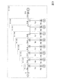
図3は、回路規模と計算速度との関係を検証するために用いた検証用回路を示す図である。図3に示す検証用回路は、発電機G2〜G10、変圧器TR2〜TR10、及び送電線TL1〜TL16を有しており、発電機G2〜G10がそれぞれ変圧器TR2〜TR10を介して送電網(送電線TL1〜TL16からなる送電網)に接続された回路である。この検証用回路の回路規模を図中に示す「ケース1」〜「ケース9」の9通りに変化させ、各々のケースについて周波数特性計算を行った。
FIG. 3 is a diagram showing a verification circuit used to verify the relationship between the circuit scale and the calculation speed. The verification circuit shown in FIG. 3 includes generators G2 to G10, transformers TR2 to TR10, and transmission lines TL1 to TL16, and the generators G2 to G10 are connected to the power transmission network via the transformers TR2 to TR10, respectively. It is a circuit connected to (a power transmission network composed of power transmission lines TL1 to TL16). The circuit scale of this verification circuit was changed to nine cases from “
例えば、「ケース1」は、発電機G2、変圧器TR2、及び送電線TL1,TL2からなる規模の回路であり、「ケース2」は、発電機G2,G3、変圧器TR2,TR3、及び送電線TL1,TL2,TL3,TL11からなる規模の回路である。尚、「ケース9」は、図3に示す発電機G2〜G10、変圧器TR2〜TR10、及び送電線TL1〜TL16の全てからなる規模の回路である。「ケース1」〜「ケース9」の各々におけるノード数及びブランチ数を以下の表1に示す。
For example, “
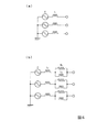
図4は、図3中の発電機G2〜G10の模擬に用いた等価回路を示す図である。図4(a)に示す通り、発電機G2〜G10の模擬に用いた等価回路は、発電機の起電力Eに、次過渡リアクタンスに相当するインダクタンスLを直列接続した回路である。発電機の次過渡インピーダンスには、周波数が高くなるにつれて表皮効果により損失が大きくなる特性があり、例えば図4(b)に示す等価回路でも模擬できると考えられる。ここでは、計算速度の評価を主目的としていることから、次過渡インピーダンスは損失成分がないと仮定し、簡易的に図4(a)に示す等価回路で模擬することとした。発電機G2〜G7,G9のインダクタンスLは32.1[μH]とし、発電機G8のインダクタンスLは64.2[μH]とし、発電機G10のインダクタンスLは10.7[μH]とした。また、電源電圧Eは短絡した。 FIG. 4 is a diagram showing an equivalent circuit used for simulating the generators G2 to G10 in FIG. As shown in FIG. 4A, the equivalent circuit used for simulating the generators G2 to G10 is a circuit in which an inductance L corresponding to the next transient reactance is connected in series to the electromotive force E of the generator. The next transient impedance of the generator has a characteristic that the loss increases due to the skin effect as the frequency increases. For example, it can be simulated by the equivalent circuit shown in FIG. Here, since the main purpose is to evaluate the calculation speed, it is assumed that the next transient impedance has no loss component and is simply simulated by the equivalent circuit shown in FIG. The inductances L of the generators G2 to G7 and G9 were 32.1 [μH], the inductance L of the generator G8 was 64.2 [μH], and the inductance L of the generator G10 was 10.7 [μH]. The power supply voltage E was short-circuited.
図5は、図3中の変圧器TR2〜TR10の模擬に用いた等価回路を示す図である。図5(a)に示す通り、変圧器TR2〜TR10の模擬に用いた等価回路は、Δ−Y接続の理想変圧器に、漏れインダクタンスL1が直列に接続された回路である。変圧器の漏れインピーダンスも発電機と同様に表皮効果によって損失が増加する特性があり、例えば図5(b)に示す等価回路でも模擬できると考えられる。ここでは、発電機の模擬と同様の理由で、漏れインピーダンスは損失成分がないと仮定し、簡易的に図5(a)に示す等価回路で模擬することとした。 FIG. 5 is a diagram showing an equivalent circuit used for simulating the transformers TR2 to TR10 in FIG. As shown in FIG. 5 (a), an equivalent circuit used to simulate the transformer TR2~TR10 is ideal transformer delta-Y connection, a circuit leakage inductance L 1 connected in series. Similarly to the generator, the transformer's leakage impedance also has a characteristic that loss increases due to the skin effect, and it is considered that it can be simulated by, for example, the equivalent circuit shown in FIG. Here, for the same reason as the simulation of the generator, it is assumed that the leakage impedance has no loss component and is simply simulated by the equivalent circuit shown in FIG.
変圧器TR2〜TR7,TR9の漏れインダクタンスL1は9.28[mH]とし、変圧器TR8の漏れインダクタンスL1は18.6[mH]とし、変圧器TR10の漏れインダクタンスL1は3.10[mH]とした。変圧比は、500[kV]:22[kV]とし、変圧器巻線の対地浮遊静電容量は、何れの変圧器も2000[pF]のキャパシタンスで模擬した。送電線TL1〜TL16は、本来であれば周波数依存分布定数線路モデルを用いた現実的な模擬をすべきであるが、ここでの検討では計算速度の評価を主目的としていることから、簡易的に相間の結合を有さないπ型等価回路モデル(1段)を用いた。 Transformer TR2~TR7, leakage inductance L 1 of TR9 is a 9.28 [mH], leakage inductance L 1 of the transformer TR8 is a 18.6 [mH], leakage inductance L 1 of the transformer TR10 3.10 [MH]. The transformation ratio was 500 [kV]: 22 [kV], and the ground floating capacitance of the transformer winding was simulated with a capacitance of 2000 [pF] for all transformers. The transmission lines TL1 to TL16 should be realistically simulated using a frequency-dependent distributed constant line model. However, since the main purpose is to evaluate the calculation speed in this study, the transmission lines TL1 to TL16 are simplified. A π-type equivalent circuit model (one stage) having no coupling between phases was used.
図3に示す「ケース1」〜「ケース9」の何れのケースにおいても、図中の母線Aから系統を見込んだインピーダンスの周波数特性計算を行った。ここで、計算周波数が広範囲であるほど、周波数サンプル間の回路方程式の差が大きくなり、本実施形態における周波数特性計算にとって不利な条件となる。そのため、ここでの検証では、通常実施される周波数範囲よりも広い0.1[Hz]から1[MHz]までとすることで、本実施形態における周波数特性計算の効果を確認することとした。周波数サンプル点は、対数軸上で等間隔に2000点とした。計算には、現在、一般的に普及しているデスクトップパソコンを用いた。
In any case of “
ここで、一般的な計算機を用いた数値計算では、倍精度演算を用いるのが標準的であり、その有効桁数はおよそ16桁となる。つまり、前述した不安定因子ρが16桁を超えた場合には、LU分解中に実行される計算(前述した(6),(7)式に示す計算)中の差分演算で情報落ちが発生し、計算精度が低下する可能性が生じる。そのため、ここでの計算では、5桁の余裕を見込んで閾値ρthを1011とした。尚、ここで用いる「ケース1」〜「ケース9」は、検証用に作成したケースであり、計算結果として得られる周波数特性自体に特別な意味はない点に注意されたい。
Here, in a numerical calculation using a general computer, it is standard to use a double precision operation, and the number of significant digits is about 16 digits. That is, when the above-mentioned unstable factor ρ exceeds 16 digits, information loss occurs in the difference calculation in the calculation executed during the LU decomposition (the calculation shown in the above-described equations (6) and (7)). However, there is a possibility that the calculation accuracy is lowered. For this reason, in this calculation, the threshold ρ th is set to 10 11 with an allowance of 5 digits. It should be noted that “
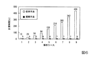
図6は、図3に示す「ケース1」〜「ケース9」について周波数特性計算を行った場合に要した計算時間を示す図である。尚、図6中の凡例「従来手法」は、図12に示す従来の方法で周波数特性計算を行ったときのものであり、凡例「提案手法」は、図2に示す本実施形態の方法で周波数特性計算を行ったときのものである。図6を参照すると、従来手法では、「ケース1」から「ケース9」の順で(つまり、回路規模が大きくなるにつれて)計算時間が増大するのに対し、提案手法では、回路規模が大きくなっても計算時間が殆ど変化しないことが分かる。
FIG. 6 is a diagram showing calculation time required when frequency characteristics are calculated for “
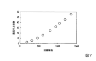
図7は、回路規模と速度向上倍数との関係を示す図である。この図7は、図6に示す各々のケースについての計算時間の比(従来手法の計算時間を提案手法の計算時間で除算して得られた値)を速度向上倍数としてプロットしたものである。尚、図6に示す各々のケースの回路規模は、前述した表1から得られる。図7を参照すると、回路規模が大きくなるにつれて速度向上倍数が大きくなることが分かる。特に、図6に示す「ケース9」の場合(回路規模が1353の場合)には、速度向上倍数が60倍近くになっており、速度向上の効果が極めて大きいことが分かる。従って、計算時間が問題となる大規模回路であるほど高速化の効果が大きく、実用的であると考えられる。 FIG. 7 is a diagram showing the relationship between the circuit scale and the speed improvement multiple. FIG. 7 is a plot of the ratio of calculation time (value obtained by dividing the calculation time of the conventional method by the calculation time of the proposed method) as a speed improvement multiple for each case shown in FIG. The circuit scale of each case shown in FIG. 6 is obtained from Table 1 described above. Referring to FIG. 7, it can be seen that the speed enhancement factor increases as the circuit scale increases. In particular, in the case of “Case 9” shown in FIG. 6 (when the circuit scale is 1353), the speed improvement multiple is close to 60 times, and it can be seen that the speed improvement effect is extremely large. Therefore, it can be considered that the larger the large-scale circuit in which the calculation time is a problem, the greater the effect of speeding up and the more practical.
図8は、図3に示す「ケース9」について周波数特性計算を行った場合の各サンプル点における不安定因子を示す図である。図8を参照すると、従来手法及び提案手法の不安定因子は、計算周波数が約5000[Hz]を超えるあたりまではほぼ同じ値であるが、計算周波数がそれ以上高くなると提案手法では不安定因子が急激に増大することが分かる。また、図8を参照すると、提案手法の不安定因子は、計算周波数が約500[kHz]あたりで急激に減少して、従来手法の不安定因子と同じ値に戻っていることが確認できる。これは、計算周波数が約500[kHz]あたりで提案手法の不安定因子が閾値ρth(1011)を超え、順序付けがやり直されたためである。図8から明らかな通り、全計算過程における初回の計算を含めた順序付けの計算回数は2回であり、全2000点(周波数サンプル点の数)の計算のうち1998回の順序付けが省略されている。 FIG. 8 is a diagram showing instability factors at each sample point when frequency characteristics are calculated for “Case 9” shown in FIG. 3. Referring to FIG. 8, the instability factors of the conventional method and the proposed method are almost the same values until the calculation frequency exceeds about 5000 [Hz], but if the calculation frequency becomes higher than that, the instability factor in the proposed method. It can be seen that increases rapidly. Referring to FIG. 8, it can be confirmed that the instability factor of the proposed method decreases rapidly around the frequency of about 500 [kHz] and returns to the same value as the instability factor of the conventional method. This is because the instability factor of the proposed method exceeds the threshold ρ th (10 11 ) around the calculation frequency of about 500 [kHz], and the ordering is performed again. As is apparent from FIG. 8, the number of calculations for ordering including the first calculation in all the calculation processes is two, and the ordering for 1998 is omitted from the calculation of all 2000 points (number of frequency sample points). .
(B)計算精度及び計算速度の検証
図9は、計算精度及び計算速度を検証するために用いた検証用回路を示す図である。図9に示す検証回路は、発電機G1〜G3、変圧器TR1〜TR3、周波数変換所FC、及び送電線TL1〜TL3を有しており、発電機G1〜G3がそれぞれ変圧器TR1〜TR3を介して送電網(送電線TL1〜TL3からなる送電網)に接続されるとともに、周波数変換所FCが上記の送電網に接続された275[kV]系統の回路である。この検証用回路は、交直変換器に伴う高調波不安定現象や高調波拡大現象の解析等で行われる交流系統の周波数特性の計算を想定した回路である。尚、図9においては、図示を簡単にするために、単線結線図で描かれているが、実際には全て三相モデルで構成されている。
(B) Verification of Calculation Accuracy and Calculation Speed FIG. 9 is a diagram showing a verification circuit used for verifying the calculation accuracy and calculation speed. The verification circuit shown in FIG. 9 has generators G1 to G3, transformers TR1 to TR3, a frequency converter station FC, and power transmission lines TL1 to TL3, and the generators G1 to G3 have transformers TR1 to TR3, respectively. And a frequency conversion station FC is a circuit of a 275 [kV] system connected to the power transmission network (a power transmission network including the transmission lines TL1 to TL3). This verification circuit is a circuit that assumes the calculation of the frequency characteristics of the AC system, which is performed in the analysis of the harmonic instability phenomenon and the harmonic expansion phenomenon associated with the AC / DC converter. In FIG. 9, for simplicity of illustration, a single-line diagram is drawn, but in actuality, all are configured by a three-phase model.
周波数変換所FCについては、他励式周波数変換所の回路構成(変換器、交流フィルタ、及び調相設備を備える回路構成)を用いた。この周波数変換所FCのパラメータを以下の表2に示す。 For the frequency conversion station FC, the circuit configuration of a separately excited frequency conversion station (circuit configuration including a converter, an AC filter, and phase adjusting equipment) was used. The parameters of this frequency converter station FC are shown in Table 2 below.
発電機G1〜G3は、図4(b)に示す通り、発電機の起電力を表す電圧源に初期過渡インピーダンスが直列に接続された等価回路で模擬した。初期過渡インピーダンスは表皮効果を考慮して図4(b)に示したインダクタンスL1,L2及び抵抗R2からなる回路で表現した。具体的に、発電機G1については、インダクタンスL1を0.283[mH]とし、インダクタンスL2を0.566[mH]とし、抵抗R2を0.577[Ω]とした。また、発電機G2については、インダクタンスL1を0.566[mH]とし、インダクタンスL2を1.13[mH]とし、抵抗R2を1.15[Ω]とした。また、発電機G3については、インダクタンスL1を54.5[μH]とし、インダクタンスL2を0.109[mH]とし、抵抗R2を0.111[Ω]とした。高調波の解析であるため、電源電圧Eは短絡した。 The generators G1 to G3 were simulated by an equivalent circuit in which an initial transient impedance was connected in series to a voltage source representing an electromotive force of the generator, as shown in FIG. The initial transient impedance is expressed by a circuit composed of inductances L 1 and L 2 and a resistor R 2 shown in FIG. 4B in consideration of the skin effect. Specifically, for the generator G1, the inductance L 1 and 0.283 [mH], the inductance L 2 and 0.566 [mH], and the resistor R 2 and 0.577 [Omega]. Also, the generator G2, the inductance L 1 and 0.566 [mH], the inductance L 2 and 1.13 [mH], and the resistor R 2 and 1.15 [Omega]. Also, the generator G3, the inductance L 1 and 54.5 [.mu.H], the inductance L 2 and 0.109 [mH], and the resistor R 2 and 0.111 [Omega]. The power supply voltage E was short-circuited because of harmonic analysis.
変圧器TR1〜TR3は、図5(b)に示す通り、Δ−Y接続の理想変圧器に、漏れインピーダンスが直列に接続された等価回路で模擬した。変圧器TR1〜TR3の漏れインピーダンスは、図5(b)に示したインダクタンスL1,L2及び抵抗R2からなる回路で表現した。具体的に、変圧器TR1については、インダクタンスL1を24.2[mH]とし、インダクタンスL2を4.78[mH]とし、抵抗R2を12.7[Ω]とした。また、変圧器TR2については、インダクタンスL1を46.5[mH]とし、インダクタンスL2を11.5[mH]とし、抵抗R2を29.6[Ω]とした。また、変圧器TR3については、インダクタンスL1を4.84[mH]とし、インダクタンスL2を0.955[mH]とし、抵抗R2を2.55[Ω]とした。変圧比は、275[kV]:22[kV]とし、変圧器巻線の対地浮遊静電容量は、何れの変圧器も2000[pF]のキャパシタンスで模擬した。 As shown in FIG. 5B, the transformers TR1 to TR3 are simulated by an equivalent circuit in which a leakage impedance is connected in series to an ideal transformer of Δ-Y connection. The leakage impedance of the transformers TR1 to TR3 is expressed by a circuit including the inductances L 1 and L 2 and the resistor R 2 shown in FIG. Specifically, for the transformer TR1, the inductance L 1 and 24.2 [mH], the inductance L 2 and 4.78 [mH], and the resistor R 2 and 12.7 [Omega]. Also, the transformer TR2, an inductance L 1 and 46.5 [mH], the inductance L 2 and 11.5 [mH], and the resistor R 2 and 29.6 [Omega]. Also, the transformer TR3, the inductance L 1 and 4.84 [mH], the inductance L 2 and 0.955 [mH], and the resistor R 2 and 2.55 [Omega]. The transformation ratio was 275 [kV]: 22 [kV], and the floating capacitance to ground of the transformer winding was simulated with a capacitance of 2000 [pF] for all transformers.
送電線TL1〜TL3は、全て架空線で、装柱は275[kV]標準装柱であると仮定し、大地抵抗率を100[Ωm]として周波数依存線路モデルで模擬した。また、送電線TL1〜TL3の亘長はそれぞれ5[km],15[km],100[km]で、周波数依存線路モデル作成時の線路定数計算周波数のサンプルは、0.1[Hz]〜10[MHz]の範囲で400点とした。 The transmission lines TL1 to TL3 are all overhead lines, and the mounting poles are assumed to be 275 [kV] standard mounting poles, and the ground resistivity is set to 100 [Ωm], and simulated by a frequency-dependent line model. The lengths of the transmission lines TL1 to TL3 are 5 [km], 15 [km], and 100 [km], respectively, and the sample of the line constant calculation frequency when creating the frequency-dependent line model is 0.1 [Hz] to 400 points were set within a range of 10 [MHz].
以上の検証用回路について、図9中の点Pから見込んだ交流系統のインピーダンスの周波数特性を1[Hz]から2000[Hz]まで1[Hz]刻みで計算した。計算には、上述した検証(図3に示す検証用回路に対する検証)で用いたデスクトップパソコンを用い、閾値ρthを1011とした。 With respect to the above verification circuit, the frequency characteristic of the impedance of the AC system estimated from the point P in FIG. 9 was calculated in increments of 1 [Hz] from 1 [Hz] to 2000 [Hz]. For the calculation, the desktop personal computer used in the above-described verification (verification for the verification circuit shown in FIG. 3) was used, and the threshold ρ th was set to 10 11 .
図10は、図9の検証用回路に対して行った周波数特性計算の計算結果を示す図である。図10を参照すると、各周波数フィルタの共振次数の周波数においてインピーダンスが低下していることが確認できる。また、図10では、従来手法の計算結果と提案手法の計算結果との双方を描画しているが、両計算結果は良く一致しており、図10からはその違いを判別することができない。計算時間は、従来手法が約156秒であり、提案手法が約8秒であった。これは、従来手法に比べて約20倍の計算速度であり、提案手法は従来手法に比べて高速に計算できることが確認できた。 FIG. 10 is a diagram illustrating a calculation result of frequency characteristic calculation performed on the verification circuit of FIG. Referring to FIG. 10, it can be confirmed that the impedance decreases at the frequency of the resonance order of each frequency filter. In FIG. 10, both the calculation result of the conventional method and the calculation result of the proposed method are drawn, but the two calculation results are in good agreement, and the difference cannot be determined from FIG. 10. The calculation time was about 156 seconds for the conventional method and about 8 seconds for the proposed method. This is about 20 times faster than the conventional method, and it was confirmed that the proposed method can calculate faster than the conventional method.
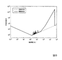
図11は、図9の検証用回路について周波数特性計算を行った場合の各サンプル点における不安定因子を示す図である。図11を参照すると、各サンプル点における不安定因子の増加は殆どなく、その推移も波形レベルで一致した。また、不安定因子の大きさは最大で105程度であり、提案手法では順序付けは繰り返されず、最も計算量が少ないケースとなった。このように、本検証では、順序付けの結果の再利用が可能であり、それにより計算速度を高速化できることが明らかになった。 FIG. 11 is a diagram showing instability factors at each sample point when frequency characteristics are calculated for the verification circuit of FIG. Referring to FIG. 11, there was almost no increase in instability factors at each sample point, and the transition was also consistent at the waveform level. The size of the instability factor is 10 approximately 5 at the maximum, ordering is not repeated in the proposed method, it became the most computational small case. Thus, in this verification, it became clear that the result of ordering can be reused, and thereby the calculation speed can be increased.
以上、本発明の一実施形態による周波数特性解析装置、方法、及びプログラムについて説明したが、本発明は上述した実施形態に制限されることなく、本発明の範囲内で自由に変更が可能である。例えば、上記実施形態では、周波数特性解析装置1が、デスクトップ型のパーソナルコンピュータによって実現される例について説明したが、周波数特性解析装置は、ネットワークに接続されたサーバの形態で実現されても良い。このような形態の場合には、例えばユーザによって操作される端末装置から解析対象及び解析条件がサーバに送信され、サーバで実施された解析の解析結果が端末装置に返信されることとなる。
The frequency characteristic analyzing apparatus, method, and program according to an embodiment of the present invention have been described above. However, the present invention is not limited to the above-described embodiment, and can be freely changed within the scope of the present invention. . For example, in the above-described embodiment, an example in which the frequency
また、上述した実施形態では、周波数特性解析装置1が周波数特性計算を行う専用の装置として説明したが、周波数特性解析装置1には、周波数特性計算機能以外の他の機能(例えば、瞬時値解析機能)が設けられていても良い。また、上記実施形態では、電力系統の周波数特性計算を行う場合を例に挙げて説明したが、本発明は疎行列演算が必要となる他の分野の解析(例えば、構造解析、流体解析等)にも適用することが可能である。本発明は、計算周波数が変更されると内容が変更されてしまう疎行列に対する疎行列演算を高速化する用途一般に適用することが可能である。
In the above-described embodiment, the frequency
1 周波数特性解析装置
14a 回路方程式作成部
14b 順序付け部
14c LU分解部
14d 計算精度評価部
14e 求解演算部
ρ 不安定因子
ρth 閾値
DESCRIPTION OF
Claims (8)
前記回路方程式作成部で作成される回路方程式のうち、特定の場合に作成された回路方程式の前記疎行列に対してのみ完全ピボッティングによる順序付けを行う順序付け部と、
前記順序付け部で直近に行われた順序付け結果を用いて前記疎行列のLU分解を行うLU分解部と、
前記LU分解部でLU分解された行列を用いて求解演算を行う求解演算部と、
を備える周波数特性解析装置。 A circuit equation creation unit for creating a circuit equation to be analyzed according to a calculation frequency using a sparse matrix;
Among the circuit equations created by the circuit equation creation unit, an ordering unit that performs ordering by complete pivoting only for the sparse matrix of the circuit equation created in a specific case,
An LU decomposition unit that performs LU decomposition of the sparse matrix using an ordering result most recently performed by the ordering unit;
A solution calculation unit that performs a solution calculation using the matrix that has been LU decomposed by the LU decomposition unit;
A frequency characteristic analyzer comprising:
前記順序付け部は、計算精度評価部で計算精度の悪化が生じたと評価された場合に、前記完全ピボッティングによる順序付けを行う、請求項1又は請求項2記載の周波数特性解析装置。 A calculation accuracy evaluation unit for evaluating calculation accuracy using the matrix decomposed by the LU decomposition unit;
The frequency characteristic analysis apparatus according to claim 1, wherein the ordering unit performs the ordering by the complete pivoting when it is evaluated that the calculation accuracy is deteriorated by the calculation accuracy evaluation unit.
前記第1ステップで作成される回路方程式のうち、特定の場合に作成された回路方程式の前記疎行列に対してのみ完全ピボッティングによる順序付けを行う第2ステップと、
前記第2ステップで直近に行われた順序付け結果を用いて前記疎行列のLU分解を行う第3ステップと、
前記第3ステップでLU分解された行列を用いて求解演算を行う第4ステップと、
前記計算周波数を変えて前記第1ステップから第4ステップを繰り返す第5ステップと、
を有する周波数特性解析方法。 A first step of creating a circuit equation to be analyzed according to a calculation frequency using a sparse matrix;
A second step of performing ordering by complete pivoting only on the sparse matrix of the circuit equation created in a specific case among the circuit equations created in the first step;
A third step of performing LU decomposition of the sparse matrix using the ordering result most recently performed in the second step;
A fourth step of performing a solution calculation using the matrix subjected to LU decomposition in the third step;
A fifth step of repeating the first step to the fourth step by changing the calculation frequency;
A frequency characteristic analysis method comprising:
前記第2ステップは、前記第1ステップで最初に回路方程式が作成された場合、或いは前記第6ステップで計算精度の悪化が生じたと評価された場合に、前記完全ピボッティングによる順序付けを行う、請求項5記載の周波数特性解析方法。 A sixth step of evaluating the calculation accuracy using the matrix subjected to LU decomposition in the third step;
The second step performs the ordering by the complete pivoting when the circuit equation is first created in the first step or when it is evaluated that the calculation accuracy is deteriorated in the sixth step. 5. The frequency characteristic analysis method according to 5.
計算周波数に応じた解析対象の回路方程式を、疎行列を用いて作成する回路方程式作成手段と、
前記回路方程式作成手段で作成される回路方程式のうち、特定の場合に作成された回路方程式の前記疎行列に対してのみ完全ピボッティングによる順序付けを行う順序付け手段と、
前記順序付け手段で直近に行われた順序付け結果を用いて前記疎行列のLU分解を行うLU分解手段と、
前記LU分解手段でLU分解された行列を用いて求解演算を行う求解演算手段と、
して機能させる周波数特性解析プログラム。 Computer
Circuit equation creation means for creating a circuit equation to be analyzed according to the calculation frequency using a sparse matrix;
Ordering means for performing ordering by complete pivoting only for the sparse matrix of the circuit equation created in a specific case among the circuit equations created by the circuit equation creation means;
LU decomposition means for performing LU decomposition of the sparse matrix using the ordering result most recently performed by the ordering means;
Solution calculation means for performing solution calculation using the matrix subjected to LU decomposition by the LU decomposition means;
Frequency characteristic analysis program to function.
前記順序付け手段は、前記回路方程式作成手段で最初に回路方程式が作成された場合、或いは前記計算精度評価手段で計算精度の悪化が生じたと評価された場合に、前記完全ピボッティングによる順序付けを行う、請求項7記載の周波数特性解析プログラム。 Further causing the computer to function as calculation accuracy evaluation means for evaluating calculation accuracy using the matrix subjected to LU decomposition by the LU decomposition means;
The ordering unit performs the ordering by the complete pivoting when the circuit equation is first created by the circuit equation creation unit or when it is evaluated that the calculation accuracy is deteriorated by the calculation accuracy evaluation unit. Item 8. The frequency characteristic analysis program according to Item 7.
Priority Applications (1)
| Application Number | Priority Date | Filing Date | Title |
|---|---|---|---|
| JP2016084172A JP6650333B2 (en) | 2016-04-20 | 2016-04-20 | Frequency characteristic analyzer, method, and program |
Applications Claiming Priority (1)
| Application Number | Priority Date | Filing Date | Title |
|---|---|---|---|
| JP2016084172A JP6650333B2 (en) | 2016-04-20 | 2016-04-20 | Frequency characteristic analyzer, method, and program |
Publications (2)
| Publication Number | Publication Date |
|---|---|
| JP2017194811A true JP2017194811A (en) | 2017-10-26 |
| JP6650333B2 JP6650333B2 (en) | 2020-02-19 |
Family
ID=60155518
Family Applications (1)
| Application Number | Title | Priority Date | Filing Date |
|---|---|---|---|
| JP2016084172A Active JP6650333B2 (en) | 2016-04-20 | 2016-04-20 | Frequency characteristic analyzer, method, and program |
Country Status (1)
| Country | Link |
|---|---|
| JP (1) | JP6650333B2 (en) |
Cited By (2)
| Publication number | Priority date | Publication date | Assignee | Title |
|---|---|---|---|---|
| JP2019219811A (en) * | 2018-06-18 | 2019-12-26 | 富士通株式会社 | Simultaneous equation processing apparatus, simultaneous equation processing method and simultaneous equation processing program |
| CN113255259A (en) * | 2021-05-21 | 2021-08-13 | 北京华大九天科技股份有限公司 | Parallel solving method based on large-scale integrated circuit division |
-
2016
- 2016-04-20 JP JP2016084172A patent/JP6650333B2/en active Active
Cited By (3)
| Publication number | Priority date | Publication date | Assignee | Title |
|---|---|---|---|---|
| JP2019219811A (en) * | 2018-06-18 | 2019-12-26 | 富士通株式会社 | Simultaneous equation processing apparatus, simultaneous equation processing method and simultaneous equation processing program |
| JP7089174B2 (en) | 2018-06-18 | 2022-06-22 | 富士通株式会社 | Simultaneous equation processing device, simultaneous equation processing method and simultaneous equation processing program |
| CN113255259A (en) * | 2021-05-21 | 2021-08-13 | 北京华大九天科技股份有限公司 | Parallel solving method based on large-scale integrated circuit division |
Also Published As
| Publication number | Publication date |
|---|---|
| JP6650333B2 (en) | 2020-02-19 |
Similar Documents
| Publication | Publication Date | Title |
|---|---|---|
| Schiessel et al. | Generalized viscoelastic models: their fractional equations with solutions | |
| Fontana et al. | A new simulation program for analog circuits using symbolic analysis techniques | |
| CN104300530A (en) | Method and device for estimating grid properties of a power grid | |
| Holters et al. | Physical modelling of a wah-wah effect pedal as a case study for application of the nodal DK method to circuits with variable parts | |
| Alsmadi et al. | Substructure preservation sylvester-based model order reduction with application to power systems | |
| Narongrit et al. | A new design approach of fuzzy controller for shunt active power filter | |
| CN118054429A (en) | Frequency modulation capability assessment method, device, equipment and medium | |
| JP6650333B2 (en) | Frequency characteristic analyzer, method, and program | |
| JP7435951B2 (en) | Floating point number generation method, apparatus, electronic device, storage medium and computer program for integrated circuit chip verification | |
| CN106786602B (en) | A kind of distribution power system load flow calculation method | |
| JP5909488B2 (en) | Magnetic field analysis program and magnetic field analysis method | |
| CN109150049B (en) | Method for establishing motor distributed parameter model of static coordinate system | |
| CN121051440A (en) | A method and system for rapid simulation of transient waveforms of typical faults in offshore wind power | |
| Prajapati et al. | Model reduction of linear systems by using improved Mihailov stability criterion | |
| Martínez et al. | Normal form analysis of complex system models: A structure-preserving approach | |
| CN119596027A (en) | A fault ride-through test method and device for high voltage ride-through of new energy equipment | |
| CN112836165A (en) | A Transient Stable Network Equation Algorithm Based on Holomorphic Embedding | |
| Ramya et al. | Real-time simulation and performance analysis of multimachine power systems using dSPACE simulator | |
| WO2019130685A1 (en) | Power supply voltage waveform calculation method, circuit coupled magnetic field analysis method, program, and recording medium having program recorded therein | |
| CN117369264A (en) | Nonlinear fuzzy large signal modeling method for new energy grid connection stability control | |
| Overlin et al. | A hybrid algorithm for parameter estimation (HAPE) for diesel generator sets | |
| CN116205181A (en) | Harmonic balance method, equipment and medium based on neural network | |
| CN107863772B (en) | A High-Order Trajectory Sensitivity Calculation Method Based on Generalized Galerkin | |
| Lang et al. | The harmonic balance method | |
| JP7198334B2 (en) | Power supply voltage waveform calculation method, circuit coupled magnetic field analysis method, program, and recording medium recording the program |
Legal Events
| Date | Code | Title | Description |
|---|---|---|---|
| A621 | Written request for application examination |
Free format text: JAPANESE INTERMEDIATE CODE: A621 Effective date: 20190121 |
|
| A977 | Report on retrieval |
Free format text: JAPANESE INTERMEDIATE CODE: A971007 Effective date: 20191125 |
|
| A131 | Notification of reasons for refusal |
Free format text: JAPANESE INTERMEDIATE CODE: A131 Effective date: 20191203 |
|
| A521 | Request for written amendment filed |
Free format text: JAPANESE INTERMEDIATE CODE: A523 Effective date: 20191212 |
|
| TRDD | Decision of grant or rejection written | ||
| A01 | Written decision to grant a patent or to grant a registration (utility model) |
Free format text: JAPANESE INTERMEDIATE CODE: A01 Effective date: 20200107 |
|
| A61 | First payment of annual fees (during grant procedure) |
Free format text: JAPANESE INTERMEDIATE CODE: A61 Effective date: 20200120 |
|
| R150 | Certificate of patent or registration of utility model |
Ref document number: 6650333 Country of ref document: JP Free format text: JAPANESE INTERMEDIATE CODE: R150 |
|
| R250 | Receipt of annual fees |
Free format text: JAPANESE INTERMEDIATE CODE: R250 |
|
| R250 | Receipt of annual fees |
Free format text: JAPANESE INTERMEDIATE CODE: R250 |
|
| R250 | Receipt of annual fees |
Free format text: JAPANESE INTERMEDIATE CODE: R250 |