JP2017194855A - Image processing apparatus, image processing method, image processing program, and image processing system - Google Patents
Image processing apparatus, image processing method, image processing program, and image processing system Download PDFInfo
- Publication number
- JP2017194855A JP2017194855A JP2016085165A JP2016085165A JP2017194855A JP 2017194855 A JP2017194855 A JP 2017194855A JP 2016085165 A JP2016085165 A JP 2016085165A JP 2016085165 A JP2016085165 A JP 2016085165A JP 2017194855 A JP2017194855 A JP 2017194855A
- Authority
- JP
- Japan
- Prior art keywords
- dimensional
- light source
- image processing
- light
- image data
- Prior art date
- Legal status (The legal status is an assumption and is not a legal conclusion. Google has not performed a legal analysis and makes no representation as to the accuracy of the status listed.)
- Pending
Links
Images


Landscapes
- Processing Or Creating Images (AREA)
- Image Processing (AREA)
- Facsimile Image Signal Circuits (AREA)
Abstract
Description
本発明は、画像処理装置、画像処理方法、画像処理プログラム、及び画像処理システムに関する。 The present invention relates to an image processing apparatus, an image processing method, an image processing program, and an image processing system.
近年、CADのような三次元モデル作成ソフトを用いて、xyz座標軸で表される三次元空間に三次元モデルを作成して全体像を把握した後、それを元に各部の設計や生産を行うことが一般化している。
また、3Dプリンタの登場以前では、三次元空間に作成された三次元モデルをディスプレイのような二次元媒体上でしか確認することができなかったが、3Dプリンタが登場したことにより、3Dプリンタで簡易的な三次元体を作成することで立体感を掴むことが可能になり、全体像をイメージすることが容易になった。
In recent years, using a three-dimensional model creation software such as CAD, a three-dimensional model is created in a three-dimensional space represented by xyz coordinate axes, and an overall image is grasped. Then, each part is designed and produced based on the three-dimensional model. It is generalized.
Prior to the advent of 3D printers, a 3D model created in a 3D space could only be confirmed on a 2D medium such as a display. However, with the advent of 3D printers, By creating a simple three-dimensional body, it is possible to grasp the three-dimensional effect, making it easier to image the whole image.
しかし、3Dプリンタは二次元媒体上に表現された三次元構造を再現することに適している反面、一つの三次元体を作成するのに多くの時間を要する。また、3Dプリンタによって作成される三次元体は、プリンタのような画像形成装置によって印刷される画像に比べて位置精度が著しく低下し、また、三次元モデルが複雑な色で形成されたものである場合、3Dプリンタでは色を再現できないため、大まかな三次元構造を再現できたとしても、本来の特徴を掴みきれないという課題があった。 However, although a 3D printer is suitable for reproducing a three-dimensional structure expressed on a two-dimensional medium, it takes a lot of time to create one three-dimensional body. In addition, a three-dimensional body created by a 3D printer has a significantly lower positional accuracy than an image printed by an image forming apparatus such as a printer, and a three-dimensional model is formed with complex colors. In some cases, 3D printers cannot reproduce colors, and there is a problem that even if a rough three-dimensional structure can be reproduced, the original features cannot be grasped.
そこで、三次元の被写体や三次元モデルを二次元媒体上で三次元的に見えるよう立体視認性を向上させるための技術が知られている。 Therefore, a technique for improving stereoscopic visibility so that a three-dimensional subject or a three-dimensional model can be viewed three-dimensionally on a two-dimensional medium is known.
人間が二次元媒体上に表示又は印刷された画像から三次元構造の立体感を把握する際には、影や光沢といった画像を形成する色情報を無意識的に捉えることにより行われる。
影については、例えば写真を撮影したときの光源の位置に依存して被写体の表面に当たる光量が場所によって異なることで、相対的な色情報の変化として視認できるものであり、ユーザは写真に現れた影を無意識的に捉えることで三次元構造を認識することができる。その他にも、三次元モデル作成ソフトで作成された三次元モデルと同一空間内に仮想的な光源を設定することで、三次元モデルの表面に照射される光量を相対的に変化させ、影を作成することも可能である。
When a human grasps the stereoscopic effect of a three-dimensional structure from an image displayed or printed on a two-dimensional medium, it is performed by unconsciously capturing color information forming an image such as a shadow or gloss.
For shadows, for example, the amount of light hitting the surface of the subject varies depending on the location depending on the position of the light source when the photograph was taken, so that it can be visually recognized as a change in relative color information, and the user appeared in the photograph The 3D structure can be recognized by capturing the shadows unconsciously. In addition, by setting a virtual light source in the same space as the 3D model created by the 3D model creation software, the amount of light irradiated on the surface of the 3D model can be changed relatively, and shadows It is also possible to create it.
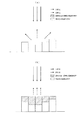
光沢については、例えばプリンタのような画像形成装置によって有彩色トナーや有彩色インクのような有彩色の画像形成材の上に透明トナーや透明インクのような透明又は半透明な画像形成材を重ねて塗布されることで画像に現れるものであり、画像の立体感を高めたい場合に有効である。光沢度は画像平面の平滑性に依存しており、図11(a)に示すように、有彩色の画像形成材のみで形成された画像の表面は凹凸が多く、表面の反射光が乱反射することで光沢度が低い。
これに対して、図11(b)に示すように、有彩色の画像形成材で形成された画像の表面が平らになるように透明又は半透明な画像形成材を塗布することで、表面の反射光が均一な方向に反射されるようになり、凹凸が多い表面に比べて光沢度が高い。
For gloss, for example, an image forming apparatus such as a printer overlays a transparent or translucent image forming material such as transparent toner or transparent ink on a chromatic image forming material such as chromatic color toner or chromatic color ink. It is effective when it is desired to enhance the stereoscopic effect of the image. The glossiness depends on the smoothness of the image plane. As shown in FIG. 11A, the surface of the image formed only with the chromatic image forming material has many irregularities, and the reflected light on the surface is irregularly reflected. The glossiness is low.
On the other hand, as shown in FIG. 11B, by applying a transparent or translucent image forming material so that the surface of the image formed with the chromatic image forming material becomes flat, Reflected light is reflected in a uniform direction, and the glossiness is higher than that of a surface with many irregularities.
光沢度を調整することで立体感を表現する技術として、例えば特許文献1には、印刷対象となる画像情報に対し、輝度の高いところは明るく、暗いところは艶消しして印刷されるようサーマルヘッドによる加熱温度を調整することで、印刷媒体の表面に光沢の分布を発生させ、画像に立体感を付与することが開示されている。
As a technique for expressing a three-dimensional effect by adjusting the gloss level, for example,
また、特許文献2には、写真プリントや印刷物などのハードコピーにおいて、印刷画像に存在する物体に応じて、金属性やガラス製などの光沢性の高い物体の領域は表面粗さを小さくし、木製や布製などの光沢性の低い物体の領域は表面粗さを大きくするように物体を形成する領域ごとの表面粗さを調整することにより、画像の立体感を好適に表現することが記載されている。さらに、物体の位置に応じて光沢性の高い物体が手前に存在する場合は、その領域の表面粗さを小さくして、それ以外の領域の表面粗さを大きくし、逆に光沢性の低い物体が手前に存在する場合には、その領域の表面粗さを大きくして、それ以外の領域の表面粗さを小さくすることで画像の立体感を好適に表現することが開示されている。
Further, in
従来の画像形成装置では二次元画像データから、文字領域、画像領域といった像域分離情報を解析してそれぞれに適した画像処理を施し、印刷媒体に塗布する画像形成材の塗布量を決定することは行われていた。
しかし、二次元画像データの色情報が特定の光源の影響を受けたものであるか否かの判断や、対象となる画素が特定の光源から照射される光が当たらない領域と特定の光源から照射される光が直接当たる領域のどちらを示しているのかの判断は、二次元画像データを解析するだけではできなかった。
そのため、光源の影響度合いを考慮した画像処理は行うことができず、画素毎の光源の影響度合いを考慮した立体視認性を向上させる処理を行うことができなかった。
A conventional image forming apparatus analyzes image area separation information such as a character area and an image area from two-dimensional image data, performs image processing suitable for each, and determines an application amount of an image forming material to be applied to a print medium. Was done.
However, it is possible to determine whether the color information of the two-dimensional image data is affected by a specific light source, and whether the target pixel is not exposed to light emitted from the specific light source and the specific light source. It was not possible to determine which of the areas directly exposed to the irradiated light was by simply analyzing the two-dimensional image data.
For this reason, image processing that takes into account the degree of influence of the light source cannot be performed, and processing for improving stereoscopic visibility that takes into account the degree of influence of the light source for each pixel cannot be performed.
特許文献1には、画像情報の輝度に基づいて光沢度を調整することで立体感を付与することは記載されているが、被写体や三次元モデルが光源の影響を受けている場合は、被写体や三次元モデルの表面の輝度自体が低いのか、光源から照射される光量が低いことにより輝度が低いのかが考慮されていない。そのため、物体の三次元構造を認識する要素のひとつである影に対して的確な処理がされず、三次元構造を表現するには不十分であった。
特許文献2には、印刷画像に存在する物体の光沢性や位置関係に基づいて光沢度を調整することで立体感を好適に表現することは開示されているが、物体そのものの再現性を高める処理が行われているだけであり、影に着目して立体視認性を更に向上させるための処理が行われているものではない。
本発明は、上記に鑑みてなされたもので、その目的は、三次元空間における三次元モデルを特定の観測点から観測して取得した二次元画像データに対し、光源の影響度合いに基づく処理を施すことで、二次元画像データの立体視認性を向上させることにある。 The present invention has been made in view of the above, and its purpose is to perform processing based on the degree of influence of a light source on two-dimensional image data obtained by observing a three-dimensional model in a three-dimensional space from a specific observation point. This is to improve the stereoscopic visibility of the two-dimensional image data.
上述した課題を解決するために、本発明は、三次元空間における特定の観測点から三次元空間に存在する三次元モデルを観測して得られる二次元画像データに対して画像処理を施す画像処理装置であって、三次元空間に存在する光源の三次元位置情報に基づいて、二次元画像データを構成する画素における三次元空間に存在する光源の影響度合いを示す陰影情報を取得する陰影情報取得部と、陰影情報取得部によって取得された陰影情報に基づいて、二次元画像データの立体視認性を高める強調処理を施す補正部と、を備えることを特徴とする。 In order to solve the above-described problems, the present invention provides image processing for performing image processing on two-dimensional image data obtained by observing a three-dimensional model existing in a three-dimensional space from a specific observation point in the three-dimensional space. Shadow information acquisition that is a device and acquires shadow information indicating the degree of influence of a light source existing in a three-dimensional space in a pixel constituting two-dimensional image data based on the three-dimensional position information of the light source existing in the three-dimensional space. And a correction unit that performs an enhancement process that increases the stereoscopic visibility of the two-dimensional image data based on the shadow information acquired by the shadow information acquisition unit.
本発明によれば、三次元座標を有するデータから取得した二次元画像データの二次元媒体上における立体視認性を向上させる処理を行うことができる。 ADVANTAGE OF THE INVENTION According to this invention, the process which improves the stereoscopic visibility on the two-dimensional medium of the two-dimensional image data acquired from the data which have a three-dimensional coordinate can be performed.
以下に、添付図面を参照しながら、本発明に係る画像形成装置における透明トナーの塗布量決定手法の具体的な実施形態について説明する。以下で示す実施形態は、透明トナーを用いた電子写真方式の画像形成装置における透明トナーの塗布量決定手法を示すが、光沢を表現する画像形成材は透明トナーに限るものではなく、例えば透明インクであっても可能である。また、光沢を表現する画像形成材の塗布量を算出する装置は画像形成装置に限るものではなく、例えばPCやスマートフォンといった情報処理端末であっても可能である。 A specific embodiment of a transparent toner coating amount determination method in an image forming apparatus according to the present invention will be described below with reference to the accompanying drawings. The embodiment described below shows a method for determining the application amount of transparent toner in an electrophotographic image forming apparatus using transparent toner, but the image forming material that expresses gloss is not limited to transparent toner. For example, transparent ink Even that is possible. Further, the apparatus for calculating the application amount of the image forming material that expresses gloss is not limited to the image forming apparatus, and may be an information processing terminal such as a PC or a smartphone.
<画像形成装置>
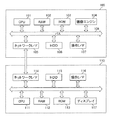
図1は本発明の一実施形態に係る画像処理装置として機能する画像形成装置100および情報処理端末110のハードウェア構成について説明する図である。
画像形成装置100は、MFPやプリンタなど、印刷媒体に対し画像形成材を用いて画像を形成する機能を有する装置である。情報処理端末110は例えばPCやスマートフォンなどであり、ディスプレイとユーザが操作するための操作部を有し、多種多様な処理を行うための端末である。
図1に示すように、本実施形態に係る画像形成装置100は、CPU(Central Processing Unit)101、RAM(Random Access Memory)102、ROM(Read Only Memory)103、画像エンジン104、ネットワークI/F(Interface)105、HDD(Hard Disk Drive)106、操作I/F107がバス108を介して接続されている。
また、本実施形態に係る情報処理端末110は、CPU111、RAM112、ROM113、ネットワークI/F114、HDD115、操作I/F116、ディスプレイ117がバス118を介して接続されている。画像形成装置100および情報処理端末110はLANなどのネットワークを介して接続されている。
<Image forming apparatus>
FIG. 1 is a diagram illustrating a hardware configuration of an
The
As shown in FIG. 1, an
In the
CPU101は画像形成装置100における演算処理装置であり、制御プログラムに基づいて画像形成装置100の全体の動作を制御する。RAM102は情報を高速で読み書きするための揮発性の記憶媒体であり、CPU101が制御プログラムを実行する際のワークエリアとして機能する。ROM103は制御プログラムが記憶されている読み出し専用の不揮発性の記憶媒体である。画像エンジン104は印刷媒体に対して画像形成を実行する機構である。
The
ネットワークI/F105は、LANなどのネットワークに接続する通信インターフェースであり、本実施形態においては、3DスキャナやPC、スマートフォン等の端末に接続される。HDD106は情報の読み書きが可能な大容量の不揮発性の記憶媒体であり、制御プログラムやアプリケーション等が記憶されている。HDD106は、SSD(Solid State Drive)などの他の形式の記憶装置であってもよい。
The network I /
操作I/F107はキーボードやタッチパネルなどによりユーザからの入力を受け付けるインターフェースである。操作I/F107からの情報はCPU101に出力される。CPU101はROM103やHDD106に記憶されている各種プログラムを実行するほか、操作I/F107やネットワークI/F105を介して情報処理端末110との通信が可能となっている。
The operation I /
CPU111は情報処理端末110における演算処理装置であり、制御プログラムに基づいて情報処理端末110の全体の動作を制御する。RAM112は情報を高速で読み書きするための揮発性の記憶媒体であり、CPU111が制御プログラムを実行する際のワークエリアとして機能する。ROM113は制御プログラムが記憶されている読み出し専用の不揮発性の記憶媒体である。
The CPU 111 is an arithmetic processing unit in the
ネットワークI/F114は、LANなどのネットワークに接続する通信インターフェースであり、本実施形態においては、画像形成装置100に接続される。HDD115は情報の読み書きが可能な大容量の不揮発性の記憶媒体であり、制御プログラムやアプリケーション等が記憶されている。HDD115は、SSDなどの他の形式の記憶装置であってもよい。
The network I /
操作I/F116はキーボードやタッチパネルなどによりユーザからの入力を受け付けるインターフェースである。操作I/F116からの情報はCPU111に出力される。CPU111はROM113やHDD115に記憶されている各種プログラムを実行するほか、操作I/F116やネットワークI/F114を介して画像形成装置100との通信が可能となっている。ディスプレイ117は表示機能を有する液晶パネルであり、操作I/Fを介したユーザからの操作を反映させて表示する。
The operation I /
<画像エンジン>
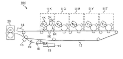
図2は本発明の一実施形態に係る画像エンジン104の構成例について説明する図である。
図2に示すように、転写ベルト12に沿って各色の現像ユニット11K、11C、11M、11Y、11Tが並べられている。現像ユニット11K、11C、11M、11Y、11Tは転写ベルト12上にトナー画像を形成するためのユニットである。
画像形成に際し、感光体1Kの外周面は暗中にて帯電器2Kにより一様に帯電された後、露光器からの露光ビーム3Kにより感光体1K上に静電潜像が形成される。現像器4Kは、この静電潜像をトナーにより可視像化し、このことにより感光体1K上にトナー画像が形成される。
このトナー画像は感光体1Kと転写ベルト12とが接する位置で、一次転写チャージャ5Kの働きにより転写ベルト12上に一次転写される。一次転写により、転写ベルト12上にトナー画像が形成される。トナー画像の一次転写が終了した感光体1Kは、外周面に残留した不要なトナーをクリーニングブレード6Kにより払拭された後、次の画像形成のために待機する。
<Image engine>
FIG. 2 is a diagram for explaining a configuration example of the
As shown in FIG. 2, developing
In forming an image, the outer peripheral surface of the photoreceptor 1K is uniformly charged by the charger 2K in the dark, and then an electrostatic latent image is formed on the photoreceptor 1K by the
This toner image is primarily transferred onto the
現像ユニット11Kによって転写ベルト12上に形成されたトナー画像は現像ユニット11Cに搬送される。
現像ユニット11Cでは、現像ユニット11Kでの画像形成プロセスと同様のプロセスにより形成されたトナー画像が、転写ベルト12上に形成されたトナー画像に重畳されて一次転写される。転写ベルト12上のトナー画像はさらに次の現像ユニット11M、11Yに搬送され、同様の動作により転写ベルト12上に重畳されて一次転写される。こうして、転写ベルト12上にフルカラーのトナー画像が形成される。
The toner image formed on the
In the developing unit 11 </ b> C, a toner image formed by the same process as the image forming process in the developing unit 11 </ b> K is superimposed and superimposed on the toner image formed on the
現像ユニット11K、11C、11M、11Yによって転写ベルト12上に形成されたフルカラーのトナー画像は現像ユニット11Tに搬送される。
現像ユニット11Tは透明トナーを一次転写するためのユニットである。現像ユニット11Tでは、現像ユニット11Kでの画像形成プロセスと同様のプロセスにより作成されたトナー画像が、転写ベルト12上に形成されたトナー画像に重畳されて一次転写される。こうして、転写ベルト12上にフルカラーのトナー画像の上に透明トナーが重畳されたトナー画像が形成される。透明トナーが重畳されたトナー画像は二次転写ローラ13の位置まで搬送され、後述するタイミングで搬送された用紙15に二次転写される。
The full-color toner image formed on the
The developing unit 11T is a unit for primary transfer of transparent toner. In the developing unit 11T, a toner image created by a process similar to the image forming process in the developing
給紙トレイ16に収納された用紙15は印刷媒体であり、画像形成に合わせて給紙ローラ17により搬送ローラ対18に順に送り出される。搬送ローラ対18に送り出された用紙15はレジストローラ対19に順に送り出される。レジストローラ対19の駆動開始は、転写ベルト12により搬送されたトナー画像と二次転写ローラ13上で、トナー画像と用紙15が適切な位置で重なり合うようなタイミングで行われる。レジストローラ対19により送り出された用紙15は、二次転写ローラ13にて転写ベルト12上のトナー画像を二次転写された後、定着器20にてトナー画像を定着され、画像形成装置100の外部に排紙される。
The paper 15 stored in the
<情報処理端末、画像形成装置>
図3は、本発明の一実施形態に係る情報処理端末110および画像形成装置100の機能構成を示す図である。
尚、本実施形態において説明する画像データ抽出部200、陰影検出部201、色補正部202、輝度補正部203、光沢補正部204、中間調処理部205の各機能は、画像形成装置100のCPU101により実現するものである。
本実施形態は、画像エンジン104による印刷媒体への印字処理を除き、ROM103に記憶されている処理に用いられるデータをHDD115等に記憶させておくことで、その内の一部又は全ての処理を情報処理端末110のCPU111によって行うものであっても良い。
<Information processing terminal and image forming apparatus>
FIG. 3 is a diagram showing a functional configuration of the
Note that the functions of the image
In the present embodiment, data used for processing stored in the
情報処理端末110は、ユーザからの入力に応じて、xyz座標系で表される三次元空間における三次元モデルの座標や色情報、面情報、光源の座標などを含んだデータであるdfx形式ファイルフォーマット等の三次元データを作成する。
The
画像データ抽出部200は、受け取った三次元データを元に、三次元モデルを特定の観測点から捉えたときの二次元画像データを抽出する。
具体的には、画像データ抽出部200は、観測点を通過する直線が三次元モデルや背景面に対して最初に交わる座標の色情報を画素値とした二次元画像データを抽出する。
<二次元画像データの抽出>
図4(a)、及び図4(b)は三次元データから二次元画像データを抽出する具体例について説明する図である。図4(a)は三次元空間に存在する三次元モデルを特定の観測点Aから捉えている図である。ここで、観測点Aを通過する直線が三次元モデルと背景面と底面に対して最初に交わる座標の色情報を取得すると、図4(b)に示すような二次元画像データが得られる。取得する座標の色情報の数は作成する二次元画像データの解像度に依存する。ここで用いられる三次元データは情報処理端末110からネットワークを介して受信する他、USBメモリ等の記録媒体を通して入手しても良い。
The image
Specifically, the image
<Extraction of 2D image data>
FIG. 4A and FIG. 4B are diagrams illustrating a specific example of extracting 2D image data from 3D data. 4A is a diagram in which a three-dimensional model existing in a three-dimensional space is captured from a specific observation point A. FIG. Here, when the color information of the coordinates at which the straight line passing through the observation point A first intersects the three-dimensional model, the background surface, and the bottom surface is acquired, two-dimensional image data as shown in FIG. 4B is obtained. The number of color information of coordinates to be acquired depends on the resolution of the two-dimensional image data to be created. The three-dimensional data used here may be obtained through a recording medium such as a USB memory in addition to being received from the
陰影検出部201は、陰影情報取得部を構成し、三次元データを基に、画像データ抽出部200によって抽出された二次元画像データの座標毎に陰影情報(id)を設定する。
陰影情報とは、三次元空間において光源からの光が直射する領域(id=1)、陰になる領域(id=2)、影になる領域(id=3)、その他の領域(id=0)を示す値である。陰になる領域(id=2)と影になる領域(id=3)は光源からの光が直射しない領域である。
The
The shadow information refers to a region (id = 1), a shaded region (id = 2), a shaded region (id = 3), and other regions (id = 0) where light from a light source directly shines in a three-dimensional space. ). The shaded area (id = 2) and the shadowed area (id = 3) are areas where light from the light source does not shine directly.
<陰影情報>
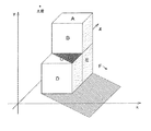
図5は三次元データにおける陰影情報について具体的に説明する図面である。
光源は三次元空間における座標の一点であり、あらゆる方向に光を照射する点である。F面は三次元モデルが置かれている面を表している底面部であり、F面を構成する座標はその他の領域(id=0)に該当する。
光が直射する領域(id=1)は、光源からの光が直射するA面、C面を構成する座標が該当する。陰になる領域(id=2)は、三次元モデルの表面側に光源からの光が直射しない座標を示しており、B面、D面、E面を構成する座標が該当する。影になる領域(id=3)は、三次元モデルによって光が遮られることにより光源からの光が直射しない座標を示しており、C面を構成する座標の一部とF面を構成する座標の一部が該当する。
<Shadow information>
FIG. 5 is a diagram for specifically explaining the shadow information in the three-dimensional data.
A light source is a point of coordinates in a three-dimensional space, and is a point that irradiates light in all directions. The F plane is a bottom surface portion representing the plane on which the three-dimensional model is placed, and the coordinates constituting the F plane correspond to other regions (id = 0).
The area where the light is directly irradiated (id = 1) corresponds to the coordinates constituting the A surface and the C surface where the light from the light source is directly irradiated. The shaded area (id = 2) indicates coordinates at which the light from the light source does not directly shine on the surface side of the three-dimensional model, and corresponds to coordinates constituting the B, D, and E planes. The shadowed area (id = 3) indicates coordinates where light from the light source is not directly irradiated by light being blocked by the three-dimensional model, and coordinates forming part of the C plane and coordinates forming the F plane. Part of this applies.
次に、光が直射する領域(id=1)と陰になる領域(id=2)の識別方法について説明する。
陰影検出部201は、光源から直線的に発せられる光線が三次元モデルを構成する面に対して貫いている向きを判断する。光線が三次元モデルを構成する面に対して表側から裏側に向けて貫いている場合には、面を構成する座標に対し光が直射する領域(id=1)に設定する。
光線が三次元モデルを構成する面に対して裏側から表側に向けて貫いている場合には、面を構成する座標に対し陰になる領域(id=2)に設定する。
ここで、表側とは三次元モデルを構成する面の内、三次元モデルの外側に面している側の面を意味し、裏側とは三次元モデルを構成する面の内、三次元モデルの内側に面している側の面を意味する。光線の貫いている方向の判断は、ベクトル演算によって行う。
Next, a method for discriminating between a region (id = 1) in which light directly shines and a region (id = 2) that is shaded will be described.
The
When the light ray penetrates from the back side to the front side with respect to the surface constituting the three-dimensional model, it is set to a region (id = 2) which is shaded with respect to the coordinates constituting the surface.
Here, the front side means the surface of the 3D model that faces the outside of the 3D model, and the back side means the 3D model of the 3D model. It means the surface facing inward. The direction in which the light beam penetrates is determined by vector calculation.
<影になる領域(id=3)の識別方法>
次に、図6(a)〜図6(c)を参照して、影になる領域(id=3)の識別方法について説明する。
図6では光源からの光線がx軸方向に対して平行に照射されている例を示しており、光源と三次元モデルのz軸座標はほぼ等しい位置関係にある。
陰影検出部201は、光源から照射されて三次元モデルの面を構成する座標を通過した光線が、背景部のxz平面および三次元モデルの内のいずれか一方と最初に交わった点の座標を影になる領域(id=3)と判断する。
図6(a)は三次元モデルの面を構成する座標を通過した光線が、背景部のxz平面を構成する座標と最初に交わった場合の例である。図6(a)ではG面を構成する座標Pを通った光線が、背景部のxz平面を構成する座標Qと最初に交わっており、このときの座標Qを影になる領域(id=3)と判断する。
図6(b)は三次元モデルの面を構成する座標を通過した光線が、三次元モデルを構成する座標と最初に交わった場合の例である。図6(b)ではG面を構成する座標Pを通過した光線が、三次元モデルを構成する座標Qと最初に交わっており、このときの座標Qを影になる領域(id=3)と判断する。
図6(c)は三次元モデルの面を構成する座標を通過した光線が、三次元モデルを構成する座標と最初に交わった場合の別の例である。図6(c)ではG面を構成する座標Pを通過した光線が、三次元モデルを構成する座標Qと最初に交わっており、このときの座標Qを影になる領域(id=3)と判断する。
<Identification method of shadow area (id = 3)>
Next, with reference to FIG. 6A to FIG. 6C, a method for identifying a shadow area (id = 3) will be described.
FIG. 6 shows an example in which light rays from the light source are irradiated in parallel to the x-axis direction, and the z-axis coordinates of the light source and the three-dimensional model are substantially equal.
The
FIG. 6A shows an example in which a light beam that has passed through the coordinates constituting the surface of the three-dimensional model first intersects with the coordinates that constitute the xz plane of the background portion. In FIG. 6 (a), the light beam passing through the coordinate P constituting the G plane first intersects with the coordinate Q constituting the xz plane of the background portion, and the coordinate Q at this time is a shadow area (id = 3). ).
FIG. 6B shows an example in which a light beam that has passed through the coordinates constituting the surface of the three-dimensional model first intersects with the coordinates that constitute the three-dimensional model. In FIG. 6B, the light beam that has passed through the coordinate P that constitutes the G plane first intersects with the coordinate Q that constitutes the three-dimensional model, and the coordinate Q at this time is a shadowed area (id = 3). to decide.
FIG. 6C shows another example in the case where the light beam that has passed through the coordinates constituting the surface of the three-dimensional model first intersects with the coordinates that constitute the three-dimensional model. In FIG. 6C, the light beam that has passed through the coordinate P that constitutes the G plane first intersects with the coordinate Q that constitutes the three-dimensional model, and the coordinate Q at this time is a shadowed area (id = 3). to decide.
陰影検出部201は、三次元データにおける背景部と三次元モデルを構成する座標毎に陰影情報(id)を設定するが、光が直射する領域(id=1)と影になる領域(id=3)が重複する領域の座標には、影になる領域(id=3)のidを設定する。また、陰影検出部201は、陰になる領域(id=2)と影になる領域(id=3)が重複する領域の座標には、陰になる領域(id=2)のidを設定する。
The
陰影検出部201は、三次元データを構成する座標に対して陰影情報(id)を設定した後、三次元空間の座標に対応する二次元画像データの画素に対して同じ陰影情報(id)を設定する。この処理により、陰影情報(id)が画素毎に設定された二次元画像データを得ることができる。
The
色補正部202は、RAM102に展開されたRGBの階調値を有する二次元画像データ(RGBデータ)を、ROM103に記憶されている色変換テーブルを参照してCMYKの階調値を有する二次元画像データ(CMYKデータ)に変換する。CMYKデータとは、CトナーによるC版、MトナーによるM版、YトナーによるY版、KトナーによるK版をそれぞれ形成するための塗布量を示すデータであり、0〜255の値をとるものとする。
The
輝度補正部203は、補正部を構成し、陰影検出部201によって判断された陰影情報に基づき、CMYKデータにおけるそれぞれの画素の輝度をROM103に記憶されているそれぞれの陰影情報(id)に対応するγカーブを参照して調整する。
光が直射する領域(id=1)に対応するγカーブは、変換後の画素の輝度が、変換前の画素の輝度よりも高くなるように設定されている。
陰になる領域(id=2)および影になる領域(id=3)に対応するγカーブは、変換後の画素の輝度が、変換前の画素の輝度よりも低くなるように設定されている。
また、影になる領域(id=3)に対応するγカーブは、陰になる領域(id=2)に対応するγカーブよりも変換前の画素の輝度と変換後の画素の輝度の変化量が大きくなるように設定されている。
輝度補正部203は、その他の領域(id=0)が設定された画素に対しては輝度の調整を行わない。このように、二次元画像データの輝度が領域毎に強調される処理を施すことで、二次元画像データの立体視認性を向上させることができる。
The
The γ curve corresponding to the region (id = 1) where light is directly irradiated is set so that the luminance of the pixel after conversion is higher than the luminance of the pixel before conversion.
The γ curves corresponding to the shadowed area (id = 2) and the shadowed area (id = 3) are set so that the luminance of the pixel after conversion is lower than the luminance of the pixel before conversion. .
Further, the γ curve corresponding to the shadowed area (id = 3) has a change amount of the luminance of the pixel before the conversion and the luminance of the pixel after the conversion than the γ curve corresponding to the shadowed area (id = 2). Is set to be large.
The
光沢補正部204は、補正部を構成し、陰影検出部201によって検出された陰影情報に基づいて塗布する透明トナー量を決定し、CMYKデータに透明トナー塗布量のデータを加えたCMYKαデータを作成する。
<透明トナーの塗布量>
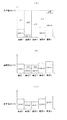
図7(a)〜(c)はそれぞれの陰影情報(id)が付与された領域における透明トナーの塗布量を決定する方法について説明する図であり、縦軸CMYK1〜5は画素1〜5に塗布されるCMYKトナー量を示しており、縦軸α1〜α5は画素1〜5に塗布される透明トナー量を示している。画素1〜5は連続した同じ陰影情報(id)が付与された画素を示している。
図7(a)は光が直射する領域(id=1)が設定された画素に対する透明トナーの塗布量を説明する図面である。
光沢補正部204は、光が直射する領域(id=1)に対し、基準値(id=1)から対象画素に塗布されるCMYKトナーの塗布量を減算した値を透明トナーの塗布量として設定する。光沢補正部204は、基準値(id=1)について、光が直射する領域(id=1)が設定された画素が連続して形成される領域における画素毎のCMYKトナーの塗布量の内、最大のものを検出し、その塗布量に一定の値を加えたものを対象となる領域の基準値(id=1)として設定しても良いし、光が直射する領域(id=1)が設定された画素毎のCMYKトナーの塗布量の内、最大のものを検出し、その塗布量に一定の値を加えたものを二次元画像データにおける基準値(id=1)として設定しても良い。
The
<Applied amount of transparent toner>
FIGS. 7A to 7C are diagrams for explaining a method of determining the application amount of the transparent toner in the region to which the respective shadow information (id) is given. The vertical axes CMYK1 to 5 are the
FIG. 7A is a diagram illustrating the amount of transparent toner applied to a pixel in which a region (id = 1) where light is directly irradiated is set.
The
図7(b)は陰になる領域(id=2)が設定された画素に対する透明トナーの塗布量を説明する図面である。
光沢補正部204は、陰になる領域(id=2)に対し、基準値(id=2)から対象画素に塗布されるCMYKトナーの塗布量を減算した値を透明トナーの塗布量として設定する。光沢補正部204は、CMYKトナーの塗布量が基準値(id=2)を上回っている場合は、透明トナーを塗布しないように設定する。光沢補正部204は、基準値(id=2)について、陰になる領域(id=2)が設定された画素が連続している領域におけるCMYKトナーの塗布量の平均値を、対象となる領域の基準値(id=2)として設定しても良いし、陰になる領域(id=2)が設定された領域のCMYKトナーの塗布量の平均値を、二次元画像データにおける基準値(id=2)として設定しても良い。
FIG. 7B illustrates the amount of transparent toner applied to a pixel in which a shaded area (id = 2) is set.
The
図7(c)は影になる領域(id=3)が設定された画素に対する透明トナーの塗布量を説明する図面である。
光沢補正部204は、影になる領域(id=3)に対し、基準値(id=3)から対象画素に塗布されるCMYKトナーの塗布量を減算した値を透明トナーの塗布量として設定する。光沢補正部204は、CMYKトナーの塗布量が基準値(id=3)を上回っている場合は、透明トナーを塗布しないように設定する。光沢補正部204は、基準値(id=3)について、影になる領域(id=3)が設定された画素が連続している領域におけるCMYKトナーの塗布量の平均値未満の値を、対象となる領域の基準値(id=3)として設定しても良いし、影になる領域(id=3)が設定された領域のCMYKトナーの塗布量の平均値未満の値を、二次元画像データにおける基準値(id=3)として設定しても良い。CMYKトナーの塗布量の平均値未満の値の設定方法として、例えば平均値の半分の値を設定する方法が挙げられる。
FIG. 7C illustrates the amount of transparent toner applied to a pixel in which a shadow area (id = 3) is set.
The
以上の光沢補正部204の処理により、光が直射する領域(id=1)、陰になる領域(id=2)、影になる領域(id=3)の順に画像の平滑性が低くなり、また透明トナーの塗布される画素数も減少することから、結果として光が直射する領域(id=1)、陰になる領域(id=2)、影になる領域(id=3)が設定されている画素の順に光沢度が低くなる。このように、印刷媒体に印刷された画像の光沢度が領域毎に異なるような強調処理を施すことで、立体視認性を向上させることができる。
By the processing of the
中間調処理部205は、各トナーの塗布量に基づきディザ処理や誤差拡散処理などの中間調処理を行い、画素毎に各トナーの塗布量を示すCMYKデータと透明トナーデータを作成する。
The
画像エンジン104は、中間調処理部205によって作成されたCMYKデータと透明トナーデータに基づき、印刷媒体に画像を形成する。
The
<陰影検出部>
図8は、本発明の一実施形態に係る陰影検出部201の処理フローを示すフローチャートである。
<Shadow detection unit>
FIG. 8 is a flowchart showing a processing flow of the
初めに、陰影検出部201は陰影検出機能がONであるか否かを判断する(S100)。ここで、陰影機能のON/OFF設定は操作I/F107または操作I/F116を操作することにより行われる。陰影検出機能がOFF設定である場合(S100、No)、処理を終了する。
陰影検出機能がON設定である場合(S100、Yes)、陰影検出部201は、三次元モデルを構成する面に対し、光源から直線的に発せられる光線が三次元モデルを構成する面に対して貫いている方向を判断し(S101)、表側から貫いている場合は(S102、Yes)、該当の三次元モデルを構成する面の座標に対し、光が直射する領域(id=1)を設定する(S103)。
一方、裏側から貫いている場合は(S102、No)、陰影検出部201は、該当の三次元モデルを構成する面の座標に対し、陰になる領域(id=2)を設定する(S104)。対象となる全ての面に対して上述した処理を行ったかを判断し、全ての面に対して処理が済んでいれば(S105、Yes)、S106に進み、処理が済んでいない面が存在していれば(S105、No)、S101に戻る。
First, the
When the shadow detection function is set to ON (S100, Yes), the
On the other hand, when penetrating from the back side (S102, No), the
全ての面に対して処理が済んでいた場合、陰影検出部201は、三次元モデルの面を構成する座標を通る光線が、背景部および三次元データを構成する三次元モデルの内のいずれか一方と最初に交わった点の座標を影になる領域(id=3)と判断する(S106)。
ここで、陰影検出部201は、(id=1)と(id=3)が重複して設定されている座標は(id=3)に設定し、(id=2)と(id=3)が重複して設定されている座標は、(id=3)に設定する(S107)。
次に、陰影検出部201はidの設定されていない三次元モデル又は背景部の座標があるか否か判断し、idの設定されていない座標がある場合には該当の画素をその他の領域(id=0)に設定する(S108)。次に、陰影検出部201は、三次元データの座標に対応する二次元画像データの画素に対して同じ陰影情報(id)を設定し(S109)、処理を終了する。
When all the surfaces have been processed, the
Here, the
Next, the
<輝度補正部>
図9は、本発明の一実施形態に係る輝度補正部203の処理フローを示すフローチャートである。輝度補正部203による処理は、陰影検出機能がONに設定されている場合に行う。
<Brightness correction unit>
FIG. 9 is a flowchart showing a processing flow of the
輝度補正部203は、対象画素のidが0であるか否かを判断する。対象画素のidが0であった場合(S200、Yes)、S205に進む。
対象画素のidが0でなかった場合(S200、No)、輝度補正部203は、対象画素のidを参照し(S201)、対象画素のid=1であればid=1に対応するγカーブを参照して輝度を調整する(S202)。
輝度補正部203は、対象画素のid=2であればid=2に対応するγカーブを参照して輝度を調整する(S203)。
輝度補正部203は、対象画素のid=3であればid=3に対応するγカーブを参照して輝度を調整する(S204)。
輝度補正部203は、すべての画素に対して処理を終えたか否か判断し(S205)、処理を終えていない画素が存在する場合(S205、No)、S200からの処理を繰り返す。すべての画素に対して処理を終えている場合(S205、Yes)、処理を終了する。
The
When the id of the target pixel is not 0 (S200, No), the
The
The
The
<光沢補正部>
図10は、本発明の一実施形態に係る光沢補正部204の処理フローを示すフローチャートである。光沢補正部による処理は、陰影検出機能がONに設定されている場合に行う。
<Gloss correction part>
FIG. 10 is a flowchart showing a processing flow of the
光沢補正部204は、同一idが連続している画素によって形成される画素領域を抽出する(S300)。
光沢補正部204は、該当画素領域を構成する画素のid=0であるか否かを判断する。光沢補正部204は、該当画素領域を構成する画素のid=0であった場合(S301、Yes)、S306に進む。
該当画素領域を構成する画素のid=0でなかった場合(S301、No)、光沢補正部204は、それぞれの画素領域を構成する画素に設定されているidを参照してidが何であるかを判断する(S302)。
光沢補正部204は、画素領域を構成する画素のid=1であれば、該当領域のうち最も多いCMYKトナーが用いられている画素を検索し、そのトナー量に所定量を加えた値を、該当領域を構成する画素の基準値(id=1)と設定する(S303)。
光沢補正部204は、画素領域を構成する画素のid=2であれば、該当領域を構成する画素のCMYKトナーの塗布量の平均値を、該当領域を構成する画素の基準値(id=2)と設定する(S304)。
光沢補正部204は、画素領域を構成する画素のid=3であれば、該当領域を構成する画素のCMYKトナーの塗布量の平均値より小さい値を、その値の該当領域を構成する画素の基準値(id=3)と設定する(S305)。
次に、光沢補正部204は、すべての画素領域を構成する画素に対して基準値を設定したか否かを判断し(S306)、設定されていない画素が存在する場合(S306、No)、設定画素領域を構成する画素に対してS301からの処理を繰り返す。
一方、すべての画素に対して基準値が設定されていた場合(S306、Yes)、光沢補正部204は、画素ごとに設定された基準値から対象画素のCMYKトナーの塗布量を減算した値を透明トナーの塗布量として設定する(S307)。
次に、光沢補正部204は、すべての画素に対して透明トナーの塗布量を設定したか否かを判断し(S308)、設定されていない画素が存在する場合(S308、No)、設定されていない画素に対してS307からの処理を繰り返す。すべての画素に対して処理を終えている場合(S308、Yes)、処理を終了する。
The
The
If the id of the pixel constituting the corresponding pixel area is not 0 (S301, No), the
If the id of the pixel constituting the pixel area is 1, the
When id = 2 of the pixels constituting the pixel area, the
When id = 3 of the pixels constituting the pixel area, the
Next, the
On the other hand, when the reference value has been set for all pixels (S306, Yes), the
Next, the
以上のように、本実施形態に係る画像形成装置100によれば、画像データ抽出部200は三次元座標を有するデータから二次元画像データを抽出し、陰影検出部201は画素領域毎に陰影情報を設定し、色補正部202は色変換テーブルを参照してRGBデータをCMYKデータに変換し、輝度補正部203は陰影情報と調整量が関係付けられた輝度調整テーブルを参照して画素領域毎に輝度を調整し、光沢補正部204は陰影情報に基づいて画素領域毎に透明トナーの塗布量を設定し、中間調処理部204は各トナーの塗布量に基づいた中間調処理を行い、画像エンジン104は中間調処理後の二次元画像データを印刷媒体に印字することで、三次元座標を有するデータから抽出した二次元画像データの光源の影響度合いをより際立たせて表現することが可能になり、抽出した二次元画像データの二次元媒体上での立体視認性を向上させることができる。
As described above, according to the
その他、輝度補正部203によって輝度補正が行われた後の立体視認性が向上した二次元画像データを、画像形成装置100のタッチパネルや情報処理端末110のディスプレイ117に表示する形態であっても良い。この形態では印刷媒体に印字する必要がなくなるため、より低コスト化が見込まれる。
In addition, two-dimensional image data with improved stereoscopic visibility after the luminance correction is performed by the
その他、輝度補正部203による輝度調整を行わず、光沢補正部204による透明トナーの塗布量の設定のみを行う形態であっても良い。この形態では輝度補正部203による輝度調整を行わないため、より短時間での処理が見込まれる。
Alternatively, the
その他、光沢補正部204による陰影情報に応じた透明トナーの塗布量の設定を行わず、輝度補正部203による陰影情報に応じた輝度調整のみを行い、透明トナーをすべての画素に対して一律に塗布する若しくはすべての画素に対して塗布しない形態であっても良い。この形態では光沢補正部204による透明トナーの塗布量の設定を行わないため、より短時間での処理が見込まれる。
In addition, the
以上、本発明の具体的な実施形態について説明したが、上述した実施形態は本発明の一例を示したものである。本発明は、上述した実施形態に限定されるものではなく、実施段階ではその要旨を逸脱しない範囲で様々な変形や変更を加えて具体化することができる。 While specific embodiments of the present invention have been described above, the above-described embodiments are examples of the present invention. The present invention is not limited to the above-described embodiments, and can be embodied with various modifications and changes without departing from the scope of the invention in the implementation stage.
<本発明の実施態様例の構成、作用、効果>
<第1態様>
本態様の画像形成装置100(画像処理装置)は、三次元空間における特定の観測点から三次元空間に存在する三次元モデルを観測して得られる二次元画像データに対して画像処理を施す画像処理装置であって、三次元空間に存在する光源の三次元位置情報に基づいて、二次元画像データを構成する画素における三次元空間に存在する光源の影響度合いを示す陰影情報(id)を取得する陰影検出部201(陰影情報取得部)と、陰影検出部201によって取得された陰影情報に基づいて、二次元画像データの立体視認性を高める強調処理を施す輝度補正部203、及び光沢補正部204(補正部)と、を備えることを特徴とする。
本態様によれば、陰影検出部201が、三次元空間に存在する光源の三次元位置情報に基づいて、二次元画像データを構成する画素における三次元空間に存在する光源の影響度合いを示す陰影情報(id)を取得する。輝度補正部203、及び光沢補正部204が、陰影検出部201によって取得された陰影情報に基づいて、二次元画像データの立体視認性を高める強調処理を施す。
これにより、三次元座標を有するデータから取得した二次元画像データの二次元媒体上における立体視認性を向上させる処理を行うことができる。
<Configuration, operation and effect of exemplary embodiment of the present invention>
<First aspect>
The image forming apparatus 100 (image processing apparatus) of this aspect performs an image process on two-dimensional image data obtained by observing a three-dimensional model existing in a three-dimensional space from a specific observation point in the three-dimensional space. Based on the three-dimensional position information of the light source existing in the three-dimensional space, the processing device obtains shadow information (id) indicating the influence degree of the light source existing in the three-dimensional space in the pixels constituting the two-dimensional image data. A shadow detection unit 201 (shadow information acquisition unit), a
According to this aspect, the
Thereby, the process which improves the three-dimensional visibility on the two-dimensional medium of the two-dimensional image data acquired from the data which have a three-dimensional coordinate can be performed.
<第2態様>
本態様の陰影情報(id)は、光源からの光が直射する領域を示す画素と光源からの光が直射しない領域を示す画素のいずれかを示す情報であり、光沢補正部204(補正部)は、光源からの光が直射する領域を示す画素と光が直射しない領域を示す画素それぞれに相反する処理を施すことを特徴とする。
本態様によれば、光沢補正部204が、光源からの光が直射する領域を示す画素と光が直射しない領域を示す画素それぞれに相反する処理を施す。
これにより、三次元座標を有するデータから取得した二次元画像データの二次元媒体上における立体視認性を向上させる処理を行うことができる。
<Second aspect>
The shade information (id) of this aspect is information indicating either a pixel indicating a region where light from the light source is directly irradiated or a pixel indicating a region where light from the light source is not directly irradiated, and the gloss correction unit 204 (correction unit). Is characterized in that opposite processing is applied to each of a pixel indicating a region where light from a light source is directly irradiated and a pixel indicating a region where light is not directly irradiated.
According to this aspect, the
Thereby, the process which improves the three-dimensional visibility on the two-dimensional medium of the two-dimensional image data acquired from the data which have a three-dimensional coordinate can be performed.
<第3態様>
本態様の輝度補正部203(補正部)は、光源からの光が直射する領域を示す画素に対して輝度を上げる処理を施し、光が直射しない領域を示す画素に対して輝度を下げる処理を施すことを特徴とする。
本態様によれば、輝度補正部203が、光源からの光が直射する領域を示す画素に対して輝度を上げる処理を施し、光が直射しない領域を示す画素に対して輝度を下げる処理を施す。
これにより、三次元座標を有するデータから取得した二次元画像データの二次元媒体上における立体視認性を向上させる処理を行うことができる。
<Third aspect>
The luminance correction unit 203 (correction unit) of this aspect performs a process of increasing the luminance for the pixel indicating the area where the light from the light source is directly irradiated, and the process of decreasing the luminance for the pixel indicating the area where the light is not directly irradiated. It is characterized by giving.
According to this aspect, the
Thereby, the process which improves the three-dimensional visibility on the two-dimensional medium of the two-dimensional image data acquired from the data which have a three-dimensional coordinate can be performed.
<第4態様>
本態様の陰影情報は、光源からの光が直射する領域を示す画素と光源からの光が直射しない領域を示す画素のいずれかを示す情報であり、光沢補正部204(補正部)は、光源からの光が直射する領域を示す画素と光が直射しない領域を示す画素の光沢度の差を広げる処理を施すことを特徴とする。
本態様によれば、光沢補正部204が、光源からの光が直射する領域を示す画素と光が直射しない領域を示す画素の光沢度の差を広げる処理を施す。
これにより、三次元座標を有するデータから取得した二次元画像データの二次元媒体上における立体視認性を向上させる処理を行うことができる。
<4th aspect>
The shade information in this aspect is information indicating either a pixel indicating a region where light from the light source is directly irradiated or a pixel indicating a region where light from the light source is not directly irradiated. The gloss correction unit 204 (correction unit) A process of widening the difference in glossiness between a pixel indicating a region where light from the direct light and a pixel indicating a region where the light is not directly irradiated is performed.
According to this aspect, the
Thereby, the process which improves the three-dimensional visibility on the two-dimensional medium of the two-dimensional image data acquired from the data which have a three-dimensional coordinate can be performed.
<第5態様>
本態様の光沢補正部204(補正部)は、画素データと陰影情報に基づいて透明又は半透明な画像形成材の塗布量を画素毎に算出することを特徴とする。
本態様によれば、光沢補正部204が、画素データと陰影情報に基づいて透明又は半透明な画像形成材の塗布量を画素毎に算出する。
これにより、三次元座標を有するデータから取得した二次元画像データの二次元媒体上における立体視認性を向上させる処理を行うことができる。
<5th aspect>
The gloss correction unit 204 (correction unit) according to this aspect is characterized in that the application amount of a transparent or translucent image forming material is calculated for each pixel based on pixel data and shading information.
According to this aspect, the
Thereby, the process which improves the three-dimensional visibility on the two-dimensional medium of the two-dimensional image data acquired from the data which have a three-dimensional coordinate can be performed.
<第6態様>
本態様として、光源からの光が直射しない領域を示す画素は、光源からの光の陰となる領域(id=2)を示す画素と光源からの光の影となる領域(id=3)を示す画素を含み、輝度補正部203又は光沢補正部204(補正部)は、それぞれの画素に対して異なる処理を施すことを特徴とする。
本態様によれば、光源からの光が直射しない領域を示す画素は、光源からの光の陰となる領域(id=2)を示す画素と光源からの光の影となる領域(id=3)を示す画素を含み、輝度補正部203又は光沢補正部204は、それぞれの画素に対して異なる処理を施す。
これにより、三次元座標を有するデータから取得した二次元画像データの二次元媒体上における立体視認性を向上させる処理を行うことができる。
<Sixth aspect>
In this embodiment, the pixel indicating the region where the light from the light source is not directly irradiated includes the pixel indicating the region (id = 2) that is the shadow of the light from the light source and the region (id = 3) that is the shadow of the light from the light source. The
According to this aspect, the pixel indicating the region where the light from the light source is not directly irradiated includes the pixel indicating the region that is shaded by the light from the light source (id = 2) and the region that is the shadow of the light from the light source (id = 3). The
Thereby, the process which improves the three-dimensional visibility on the two-dimensional medium of the two-dimensional image data acquired from the data which have a three-dimensional coordinate can be performed.
<第7態様>
本態様の画像処理方法は、三次元空間における特定の観測点から三次元空間に存在する三次元モデルを観測して得られる二次元画像データに対して画像処理を施す画像処理方法であって、
三次元空間に存在する光源の三次元位置情報に基づいて、二次元画像データを構成する画素における三次元空間に存在する光源の影響度合いを示す陰影情報を取得する陰影情報取得ステップと、
陰影情報に基づいて、二次元画像データの立体視認性を高める強調処理を施す補正ステップと、を実行することを特徴とする。
第7態様の作用、及び効果は第1態様と同様であるので、その説明を省略する。
<Seventh aspect>
The image processing method of this aspect is an image processing method for performing image processing on two-dimensional image data obtained by observing a three-dimensional model existing in a three-dimensional space from a specific observation point in the three-dimensional space,
Based on the three-dimensional position information of the light source existing in the three-dimensional space, the shadow information acquisition step for acquiring the shadow information indicating the degree of influence of the light source existing in the three-dimensional space in the pixels constituting the two-dimensional image data;
And a correction step of performing an enhancement process for enhancing the stereoscopic visibility of the two-dimensional image data based on the shadow information.
Since the operation and effect of the seventh aspect are the same as those of the first aspect, description thereof is omitted.
<第8態様>
本態様の画像処理プログラムは、三次元空間における特定の観測点から三次元空間に存在する三次元モデルを観測して得られる二次元画像データに対して画像処理を施す画像形成装置100(画像処理装置)のプロセッサに対して、三次元空間に存在する光源の三次元位置情報に基づいて、二次元画像データを構成する画素における三次元空間に存在する光源の影響度合いを示す陰影情報を取得する陰影情報取得ステップ(S100〜S109)と、陰影情報に基づいて、二次元画像データの立体視認性を高める強調処理を施す補正ステップ(S202〜S204、S203〜S205)と、を実行させる。
第8態様の作用、及び効果は第1態様と同様であるので、その説明を省略する。
<Eighth aspect>
The image processing program of this aspect is an image forming apparatus 100 (image processing) that performs image processing on two-dimensional image data obtained by observing a three-dimensional model existing in a three-dimensional space from a specific observation point in the three-dimensional space. Device) to acquire shadow information indicating the degree of influence of the light source existing in the three-dimensional space in the pixels constituting the two-dimensional image data based on the three-dimensional position information of the light source existing in the three-dimensional space. A shadow information acquisition step (S100 to S109) and a correction step (S202 to S204, S203 to S205) for performing enhancement processing for enhancing the stereoscopic visibility of the two-dimensional image data based on the shadow information are executed.
Since the operation and effect of the eighth aspect are the same as those of the first aspect, description thereof is omitted.
<第9態様>
本態様の画像処理システムは、三次元空間における特定の観測点から三次元空間に存在する三次元モデルを観測して得られる二次元画像データに対して画像処理を施す画像処理システムであって、三次元空間に存在する光源の三次元位置情報に基づいて、二次元画像データを構成する画素における三次元空間に存在する光源の影響度合いを示す陰影情報を取得する陰影検出部201(陰影情報取得部)と、陰影検出部201によって取得された陰影情報に基づいて、二次元画像データの立体視認性を高める強調処理を施す輝度補正部203、及び光沢補正部204(補正部)と、を備えることを特徴とする。
第9態様の作用、及び効果は第1態様と同様であるので、その説明を省略する。
<Ninth aspect>
The image processing system of this aspect is an image processing system that performs image processing on two-dimensional image data obtained by observing a three-dimensional model existing in a three-dimensional space from a specific observation point in the three-dimensional space, Based on the three-dimensional position information of the light source existing in the three-dimensional space, the shadow detection unit 201 (shadow information acquisition) acquires shadow information indicating the degree of influence of the light source existing in the three-dimensional space in the pixels constituting the two-dimensional image data. A
Since the operation and effect of the ninth aspect are the same as those of the first aspect, description thereof will be omitted.
100…画像形成装置、101、111…CPU、102、112…RAM、103、113…ROM、104…画像エンジン、105、114…ネットワークI/F、106、115…HDD、107、116…操作I/F、108、118…バス、117…ディスプレイ、110…情報処理端末、200…画像データ抽出部、201…陰影検出部(陰影情報取得部)、202…色補正部、203…輝度補正部(補正部)、204…光沢補正部(補正部)、205…中間調処理部
DESCRIPTION OF
Claims (9)
前記三次元空間に存在する光源の三次元位置情報に基づいて、前記二次元画像データを構成する画素における前記三次元空間に存在する光源の影響度合いを示す陰影情報を取得する陰影情報取得部と、
前記陰影情報取得部によって取得された前記陰影情報に基づいて、前記二次元画像データの立体視認性を高める強調処理を施す補正部と、を備えることを特徴とする画像処理装置。 An image processing apparatus that performs image processing on two-dimensional image data obtained by observing a three-dimensional model existing in the three-dimensional space from a specific observation point in the three-dimensional space,
A shadow information acquisition unit that acquires shadow information indicating a degree of influence of the light source existing in the three-dimensional space in the pixels constituting the two-dimensional image data based on the three-dimensional position information of the light source existing in the three-dimensional space; ,
An image processing apparatus comprising: a correction unit that performs an enhancement process for enhancing stereoscopic visibility of the two-dimensional image data based on the shadow information acquired by the shadow information acquisition unit.
前記補正部は、前記光源からの光が直射する領域を示す画素と光が直射しない領域を示す画素それぞれに相反する処理を施すことを特徴とする請求項1記載の画像処理装置。 The shadow information is information indicating one of a pixel indicating a region where light from the light source is directly irradiated and a pixel indicating a region where light from the light source is not directly irradiated;
The image processing apparatus according to claim 1, wherein the correction unit performs a process that conflicts with each of a pixel indicating a region where the light from the light source is directly irradiated and a pixel indicating a region where the light is not directly irradiated.
前記補正部は、前記光源からの光が直射する領域を示す画素と光が直射しない領域を示す画素の光沢度の差を広げる処理を施すことを特徴とする請求項1記載の画像処理装置。 The shadow information is information indicating one of a pixel indicating a region where light from the light source is directly irradiated and a pixel indicating a region where light from the light source is not directly irradiated;
The image processing apparatus according to claim 1, wherein the correction unit performs a process of widening a difference in glossiness between a pixel indicating a region where the light from the light source is directly irradiated and a pixel indicating a region where the light is not directly irradiated.
前記補正部は、それぞれの画素に対して異なる処理を施すことを特徴とする請求項2乃至5のいずれか1項記載の画像処理装置。 The pixel indicating the region where the light from the light source is not directly irradiated includes a pixel indicating a region that is a shadow of the light from the light source and a pixel indicating a region that is a shadow of the light from the light source,
The image processing apparatus according to claim 2, wherein the correction unit performs different processing on each pixel.
前記三次元空間に存在する光源の三次元位置情報に基づいて、前記二次元画像データを構成する画素における前記三次元空間に存在する光源の影響度合いを示す陰影情報を取得する陰影情報取得ステップと、
前記陰影情報に基づいて、前記二次元画像データの立体視認性を高める強調処理を施す補正ステップと、を実行することを特徴とする画像処理方法。 An image processing method for performing image processing on two-dimensional image data obtained by observing a three-dimensional model existing in the three-dimensional space from a specific observation point in the three-dimensional space,
A shadow information acquisition step for acquiring shadow information indicating a degree of influence of the light source existing in the three-dimensional space in the pixels constituting the two-dimensional image data based on the three-dimensional position information of the light source existing in the three-dimensional space; ,
An image processing method comprising: performing an enhancement process for enhancing a stereoscopic visibility of the two-dimensional image data based on the shadow information.
前記三次元空間に存在する光源の三次元位置情報に基づいて、前記二次元画像データを構成する画素における前記三次元空間に存在する光源の影響度合いを示す陰影情報を取得する陰影情報取得ステップと、
前記陰影情報に基づいて、前記二次元画像データの立体視認性を高める強調処理を施す補正ステップと、を実行させる画像処理プログラム。 For a processor of an image processing apparatus that performs image processing on two-dimensional image data obtained by observing a three-dimensional model existing in the three-dimensional space from a specific observation point in the three-dimensional space,
A shadow information acquisition step for acquiring shadow information indicating a degree of influence of the light source existing in the three-dimensional space in the pixels constituting the two-dimensional image data based on the three-dimensional position information of the light source existing in the three-dimensional space; ,
An image processing program that executes a correction step for performing enhancement processing for enhancing stereoscopic visibility of the two-dimensional image data based on the shadow information.
前記三次元空間に存在する光源の三次元位置情報に基づいて、前記二次元画像データを構成する画素における前記三次元空間に存在する光源の影響度合いを示す陰影情報を取得する陰影情報取得部と、
前記陰影情報取得部によって取得された前記陰影情報に基づいて、前記二次元画像データの立体視認性を高める強調処理を施す補正部と、を備えることを特徴とする画像処理システム。 An image processing system that performs image processing on two-dimensional image data obtained by observing a three-dimensional model existing in the three-dimensional space from a specific observation point in the three-dimensional space,
A shadow information acquisition unit that acquires shadow information indicating a degree of influence of the light source existing in the three-dimensional space in the pixels constituting the two-dimensional image data based on the three-dimensional position information of the light source existing in the three-dimensional space; ,
An image processing system comprising: a correction unit that performs an enhancement process for enhancing stereoscopic visibility of the two-dimensional image data based on the shadow information acquired by the shadow information acquisition unit.
Priority Applications (1)
| Application Number | Priority Date | Filing Date | Title |
|---|---|---|---|
| JP2016085165A JP2017194855A (en) | 2016-04-21 | 2016-04-21 | Image processing apparatus, image processing method, image processing program, and image processing system |
Applications Claiming Priority (1)
| Application Number | Priority Date | Filing Date | Title |
|---|---|---|---|
| JP2016085165A JP2017194855A (en) | 2016-04-21 | 2016-04-21 | Image processing apparatus, image processing method, image processing program, and image processing system |
Publications (1)
| Publication Number | Publication Date |
|---|---|
| JP2017194855A true JP2017194855A (en) | 2017-10-26 |
Family
ID=60156432
Family Applications (1)
| Application Number | Title | Priority Date | Filing Date |
|---|---|---|---|
| JP2016085165A Pending JP2017194855A (en) | 2016-04-21 | 2016-04-21 | Image processing apparatus, image processing method, image processing program, and image processing system |
Country Status (1)
| Country | Link |
|---|---|
| JP (1) | JP2017194855A (en) |
Citations (6)
| Publication number | Priority date | Publication date | Assignee | Title |
|---|---|---|---|---|
| JPH0765199A (en) * | 1993-08-30 | 1995-03-10 | Nippon Telegr & Teleph Corp <Ntt> | Image shadowing method |
| JP2003132350A (en) * | 2001-10-25 | 2003-05-09 | Fuji Photo Film Co Ltd | Image display method, image processing method, image processor, scanner/reader, and image signal production method |
| JP2007111125A (en) * | 2005-10-18 | 2007-05-10 | Samii Kk | Game machine |
| JP2008004085A (en) * | 2006-05-23 | 2008-01-10 | Matsushita Electric Ind Co Ltd | Image processing apparatus, image processing method, program, recording medium, and integrated circuit |
| JP2008027050A (en) * | 2006-07-19 | 2008-02-07 | Konami Digital Entertainment:Kk | Image generating apparatus, image generating method, and program |
| JP2011227458A (en) * | 2010-03-29 | 2011-11-10 | Canon Inc | Image forming apparatus |
-
2016
- 2016-04-21 JP JP2016085165A patent/JP2017194855A/en active Pending
Patent Citations (6)
| Publication number | Priority date | Publication date | Assignee | Title |
|---|---|---|---|---|
| JPH0765199A (en) * | 1993-08-30 | 1995-03-10 | Nippon Telegr & Teleph Corp <Ntt> | Image shadowing method |
| JP2003132350A (en) * | 2001-10-25 | 2003-05-09 | Fuji Photo Film Co Ltd | Image display method, image processing method, image processor, scanner/reader, and image signal production method |
| JP2007111125A (en) * | 2005-10-18 | 2007-05-10 | Samii Kk | Game machine |
| JP2008004085A (en) * | 2006-05-23 | 2008-01-10 | Matsushita Electric Ind Co Ltd | Image processing apparatus, image processing method, program, recording medium, and integrated circuit |
| JP2008027050A (en) * | 2006-07-19 | 2008-02-07 | Konami Digital Entertainment:Kk | Image generating apparatus, image generating method, and program |
| JP2011227458A (en) * | 2010-03-29 | 2011-11-10 | Canon Inc | Image forming apparatus |
Non-Patent Citations (1)
| Title |
|---|
| 池内 英夫: ""3Dプログラミングの基礎"", C MAGAZINE, vol. 11, no. 5, JPN6019051754, 1 May 1999 (1999-05-01), JP, pages 16 - 33, ISSN: 0004293900 * |
Similar Documents
| Publication | Publication Date | Title |
|---|---|---|
| US9541882B2 (en) | Print control apparatus, print system, and medium which operate using gloss effect information | |
| US9275312B2 (en) | Print control apparatus, print control system, and print control method to determine a surface-effect selection table corresponding to an acquired piece of recording medium information | |
| JP6003552B2 (en) | Display processing apparatus, display processing method, and program | |
| EP2650775B1 (en) | Display processing apparatus, display processing system, display processing method, and computer program | |
| JP5458945B2 (en) | Image forming apparatus | |
| US8477376B2 (en) | System to enable development of clear toner forms | |
| US9377742B2 (en) | Print control apparatus, and method, for selecting a control mode for use in printing image data | |
| US9083920B2 (en) | Information processing apparatus, information processing system, information processing method, and computer-readable storage medium that assign priority information indicating priority between areas in an overlapping area | |
| CN101515131B (en) | Apparatus and method for forming color image | |
| JP5874572B2 (en) | Image processing apparatus, image forming system, and image processing program | |
| JP5910183B2 (en) | Image forming apparatus and image forming information processing apparatus | |
| US8619331B2 (en) | Simulated paper texture using clear toner and glossmark on texture-less stock | |
| US9324012B2 (en) | Methods, systems and apparatus for clear texturing | |
| US12530763B2 (en) | Inspection apparatus, method of controlling the same, and storage medium | |
| JP4265421B2 (en) | Print image inspection method | |
| JP6136409B2 (en) | Display device | |
| US20150177671A1 (en) | Image processing apparatus, image forming system, and computer-readable recording medium | |
| JP6705305B2 (en) | Inspection device, inspection method and program | |
| US9111205B2 (en) | Information processing device, method, and program product generating a third object having higher display priority than a same shaped first object and lower display priority than a second object | |
| JP2019041244A (en) | Image processing apparatus, image forming apparatus, and program | |
| JP2017194855A (en) | Image processing apparatus, image processing method, image processing program, and image processing system | |
| JP2022074773A (en) | Image processing device, control method and program of image processing device | |
| JP4946415B2 (en) | Image inspection device | |
| JP2016057816A (en) | Image processing apparatus, image processing method, and image processing system | |
| JP2024080466A (en) | IMAGE PROCESSING APPARATUS, IMAGE INSPECTION APPARATUS, IMAGE PROCESSING METHOD, AND PROGRAM |
Legal Events
| Date | Code | Title | Description |
|---|---|---|---|
| A621 | Written request for application examination |
Free format text: JAPANESE INTERMEDIATE CODE: A621 Effective date: 20190208 |
|
| A977 | Report on retrieval |
Free format text: JAPANESE INTERMEDIATE CODE: A971007 Effective date: 20191225 |
|
| A131 | Notification of reasons for refusal |
Free format text: JAPANESE INTERMEDIATE CODE: A131 Effective date: 20200107 |
|
| A02 | Decision of refusal |
Free format text: JAPANESE INTERMEDIATE CODE: A02 Effective date: 20200630 |