JP2017194886A - Operating device with feedback mechanism - Google Patents
Operating device with feedback mechanism Download PDFInfo
- Publication number
- JP2017194886A JP2017194886A JP2016085836A JP2016085836A JP2017194886A JP 2017194886 A JP2017194886 A JP 2017194886A JP 2016085836 A JP2016085836 A JP 2016085836A JP 2016085836 A JP2016085836 A JP 2016085836A JP 2017194886 A JP2017194886 A JP 2017194886A
- Authority
- JP
- Japan
- Prior art keywords
- mounting piece
- plate
- main body
- operating device
- intermediate plate
- Prior art date
- Legal status (The legal status is an assumption and is not a legal conclusion. Google has not performed a legal analysis and makes no representation as to the accuracy of the status listed.)
- Granted
Links
Images

Classifications
-
- G—PHYSICS
- G06—COMPUTING OR CALCULATING; COUNTING
- G06F—ELECTRIC DIGITAL DATA PROCESSING
- G06F3/00—Input arrangements for transferring data to be processed into a form capable of being handled by the computer; Output arrangements for transferring data from processing unit to output unit, e.g. interface arrangements
- G06F3/01—Input arrangements or combined input and output arrangements for interaction between user and computer
- G06F3/016—Input arrangements with force or tactile feedback as computer generated output to the user
-
- G—PHYSICS
- G06—COMPUTING OR CALCULATING; COUNTING
- G06F—ELECTRIC DIGITAL DATA PROCESSING
- G06F3/00—Input arrangements for transferring data to be processed into a form capable of being handled by the computer; Output arrangements for transferring data from processing unit to output unit, e.g. interface arrangements
- G06F3/01—Input arrangements or combined input and output arrangements for interaction between user and computer
- G06F3/03—Arrangements for converting the position or the displacement of a member into a coded form
- G06F3/041—Digitisers, e.g. for touch screens or touch pads, characterised by the transducing means
- G06F3/0412—Digitisers structurally integrated in a display
-
- G—PHYSICS
- G06—COMPUTING OR CALCULATING; COUNTING
- G06F—ELECTRIC DIGITAL DATA PROCESSING
- G06F1/00—Details not covered by groups G06F3/00 - G06F13/00 and G06F21/00
- G06F1/16—Constructional details or arrangements
- G06F1/1613—Constructional details or arrangements for portable computers
- G06F1/1626—Constructional details or arrangements for portable computers with a single-body enclosure integrating a flat display, e.g. Personal Digital Assistants [PDAs]
-
- G—PHYSICS
- G06—COMPUTING OR CALCULATING; COUNTING
- G06F—ELECTRIC DIGITAL DATA PROCESSING
- G06F2203/00—Indexing scheme relating to G06F3/00 - G06F3/048
- G06F2203/041—Indexing scheme relating to G06F3/041 - G06F3/045
- G06F2203/04105—Pressure sensors for measuring the pressure or force exerted on the touch surface without providing the touch position
Landscapes
- Engineering & Computer Science (AREA)
- General Engineering & Computer Science (AREA)
- Theoretical Computer Science (AREA)
- Human Computer Interaction (AREA)
- Physics & Mathematics (AREA)
- General Physics & Mathematics (AREA)
- Mechanical Control Devices (AREA)
- User Interface Of Digital Computer (AREA)
Abstract
Description
本発明は、押圧操作されたときに操作本体に対してフィードバック力を与えるフィードバック機構を有する操作装置に関する。 The present invention relates to an operating device having a feedback mechanism that applies a feedback force to an operating body when a pressing operation is performed.
特許文献1に、フィードバック機構を有する入力装置に関する発明が記載されている。 Patent Document 1 describes an invention related to an input device having a feedback mechanism.
この入力装置は、支持基台上に板ばねである第1の弾性部材が固定され、第1の弾性部材によって可動基台が水平方向へ移動自在に支持されている。可動部の上にはゴム材料である第2の弾性部材が設置され、第2の弾性部材の上にパネル組立体が設置されている。第2の弾性部材が収縮することで、可動基台上でパネル組立体を垂直方向へ押し込めるようになっている。パネル組立体には、表示部材と静電容量型の第1の検知部材とが搭載されている。 In this input device, a first elastic member, which is a leaf spring, is fixed on a support base, and the movable base is supported by the first elastic member so as to be movable in the horizontal direction. A second elastic member made of a rubber material is installed on the movable part, and a panel assembly is installed on the second elastic member. By contracting the second elastic member, the panel assembly can be pushed in the vertical direction on the movable base. A display member and a capacitance type first detection member are mounted on the panel assembly.
可動基台には、力センサである第2の検知部材が設けられて、可動基台上でパネル組立体が垂直方向へ押されたことを、第2の検知部材で検知できるようになっている。また、可動基台上にゴム材料である第3の弾性部材が設置され、その上に振動発生部材が設置されている。 The movable base is provided with a second detection member that is a force sensor, and the second detection member can detect that the panel assembly is pushed in the vertical direction on the movable base. Yes. A third elastic member made of a rubber material is installed on the movable base, and a vibration generating member is installed thereon.
この入力装置では、パネル組立体が垂直方向に押されると、これが可動基台上に設けられた第2の検知部材で検知され、このときの検知出力に基づいて振動発生部材が動作し、可動基台に水平方向への振動力(フィードバック力)が与えられる。 In this input device, when the panel assembly is pushed in the vertical direction, this is detected by the second detection member provided on the movable base, and the vibration generating member is operated based on the detection output at this time, and is movable. A vibration force (feedback force) in the horizontal direction is applied to the base.
特許文献1に記載された入力装置は、支持基台上に、可動基台とパネル組立体が2段構造で配置され、可動基台を振動力の作用方向へ移動させるための第1の弾性部材(板ばね)と、パネル組立体を押し込み方向へ移動させるための第2の弾性部材(ゴム材料)とが別部材として設けられている。そのため、弾性部材の数が多く必要になり、部品点数が多くなっている。 In the input device described in Patent Document 1, a movable base and a panel assembly are arranged in a two-stage structure on a support base, and a first elasticity for moving the movable base in an acting direction of a vibration force. A member (leaf spring) and a second elastic member (rubber material) for moving the panel assembly in the pushing direction are provided as separate members. Therefore, a large number of elastic members are required and the number of parts is increased.
また、パネル組立体の押圧動作を検知するための第2の検知部材(力センサ)と振動発生部材とが、可動基台とパネル組立体との間に配置されている。このように、支持基台上に、可動基台とパネル組立体とが2段構造で重ねられ、可動基台とパネル組立体との間に、第2の検知部材と振動発生部材とが介在する構造であるため、入力装置の全体構造を薄型化することが難しい。 Further, a second detection member (force sensor) and a vibration generating member for detecting the pressing operation of the panel assembly are arranged between the movable base and the panel assembly. As described above, the movable base and the panel assembly are stacked in a two-stage structure on the support base, and the second detection member and the vibration generating member are interposed between the movable base and the panel assembly. Therefore, it is difficult to reduce the overall structure of the input device.
本発明は上記従来の課題を解決するものであり、弾性部材の数を減らすことができ、また薄型に構成でき、しかも操作面が押されたときに装置本体を押圧方向へ移動させることができ、さらにフィードバック機構によって、装置本体を水平方向へ駆動することが可能なフィードバック機構を有する操作装置を提供することを目的としている。 The present invention solves the above-described conventional problems, can reduce the number of elastic members, can be configured to be thin, and can move the apparatus main body in the pressing direction when the operation surface is pressed. Another object of the present invention is to provide an operating device having a feedback mechanism capable of driving the apparatus main body in the horizontal direction by a feedback mechanism.
本発明は、表面が操作面とされた装置本体と、前記操作面が押されたことを検知する検知部材と、前記装置本体に設けられたフィードバック機構と、基台に前記装置本体を固定する複数の支持金属板とが設けられた操作装置において、
それぞれの前記支持金属板は、前記装置本体と前記基台の一方に固定される第1の取付片と、他方に固定される第2の取付片と、前記第1の取付片と前記第2の取付片との間に位置する中間板部とが一体に形成されており、
前記第1の取付片の板面は、前記操作面とほぼ平行に設置され、前記第2の取付片の板面の少なくとも一部は前記操作面とほぼ垂直に設置されており、
前記フィードバック機構によって、前記装置本体に対して、前記第2の取付片の板面と交差する向きのフィードバック力が与えられ、前記操作面が押されたときに、前記中間板部が押圧方向へ弾性変形可能であることを特徴とするものである。
The present invention fixes an apparatus main body whose surface is an operation surface, a detection member for detecting that the operation surface is pressed, a feedback mechanism provided in the apparatus main body, and a base to which the apparatus main body is fixed. In an operating device provided with a plurality of supporting metal plates,
Each of the supporting metal plates includes a first mounting piece fixed to one of the apparatus main body and the base, a second mounting piece fixed to the other, the first mounting piece, and the second mounting plate. The intermediate plate portion located between the mounting piece is integrally formed,
The plate surface of the first mounting piece is installed substantially parallel to the operation surface, and at least a part of the plate surface of the second mounting piece is installed substantially perpendicular to the operation surface,
By the feedback mechanism, a feedback force in a direction intersecting the plate surface of the second mounting piece is given to the apparatus main body, and when the operation surface is pressed, the intermediate plate portion moves in the pressing direction. It is characterized by being elastically deformable.
本発明の操作装置は、複数の前記支持金属板が、前記第2の取付片が同じ向きで互いに平行に配置されているものである。 In the operating device according to the present invention, the plurality of supporting metal plates are arranged in parallel with each other with the second mounting pieces in the same direction.
本発明の操作装置は、前記支持金属板が、前記第1の取付片と前記中間板部との境界部および前記中間板部と前記第2の取付片との境界部の、それぞれの境界部で折られており、前記中間板部の板面が、前記第1の取付片の板面と前記第2の取付片の板面の双方に対して傾斜しているものとして構成できる。 In the operating device according to the present invention, the support metal plate includes a boundary portion between the first attachment piece and the intermediate plate portion, and a boundary portion between the intermediate plate portion and the second attachment piece. The plate surface of the intermediate plate portion is inclined with respect to both the plate surface of the first attachment piece and the plate surface of the second attachment piece.
あるいは、前記支持金属板は、前記第1の取付片と前記第2の取付片との間が所定の曲率を有する湾曲面を介して連続しており、前記湾曲面が前記中間板部とされているものとして構成できる。 Alternatively, the support metal plate is continuous between the first attachment piece and the second attachment piece via a curved surface having a predetermined curvature, and the curved surface is the intermediate plate portion. Can be configured.
または、前記支持金属板は、前記第1の取付片と前記第2の取付片との境界部で折られて、前記第1の取付片の板面と前記第2の取付片の板面とがほぼ直角に対向しており、前記第1の取付片の途中から前記境界部までが前記中間板部とされ、この中間板部が、前記装置本体または前記基台から浮いているものとして構成できる。 Alternatively, the supporting metal plate is folded at a boundary portion between the first attachment piece and the second attachment piece, and the plate surface of the first attachment piece and the plate surface of the second attachment piece are Are substantially perpendicular to each other, and the intermediate plate portion extends from the middle of the first mounting piece to the boundary portion, and this intermediate plate portion is configured to float from the apparatus main body or the base. it can.
本発明の操作装置における前記支持金属板は、前記第2の取付片を前記操作面と平行な向きに曲げるときの曲げ剛性よりも、前記第2の取付片を前記操作面と垂直な向きに押し込んだときの前記中間板部の曲げ剛性の方が高いことが好ましい。 The supporting metal plate in the operating device of the present invention has the second mounting piece in a direction perpendicular to the operating surface, rather than bending rigidity when the second mounting piece is bent in a direction parallel to the operating surface. It is preferable that the intermediate plate portion has a higher bending rigidity when pushed.
本発明の入力装置は、基台上で装置本体を支持している複数の支持金属板が設けられ、この支持金属板の弾性変形よって、装置本体を、フィードバック力が作用する方向へ移動させることができるとともに、操作面を押し込む方向へも移動させることができる。よって、従来のように、装置本体をフィードバック力の方向へ移動させる弾性部材と、装置本体を押し込む方向へ移動させる弾性部材を別々に設ける必要がなく、部品点数を少なくできる。さらに、従来のように前方へ複数段に重ねる構造を採用する必要がないため、装置を薄型に構成することが可能である。 The input device of the present invention is provided with a plurality of supporting metal plates supporting the device main body on a base, and the device main body is moved in a direction in which a feedback force acts by elastic deformation of the supporting metal plate. In addition, the operation surface can be moved in the pushing direction. Therefore, unlike the conventional case, it is not necessary to separately provide an elastic member that moves the apparatus main body in the direction of the feedback force and an elastic member that moves the apparatus main body in the direction of pushing in the apparatus main body, and the number of parts can be reduced. Furthermore, since it is not necessary to adopt a structure in which a plurality of stages are stacked forward as in the prior art, the apparatus can be configured to be thin.
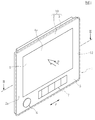
図1と図2に本発明の実施の形態としてフィードバック機構を有する操作装置1が示されている。操作装置1は車載用である。 1 and 2 show an operating device 1 having a feedback mechanism as an embodiment of the present invention. The operating device 1 is for vehicle use.
操作装置1は装置本体10を有している。装置本体10は、前方のパネル部2と後方の筐体部3とを有している。パネル部2は前方の表面が化粧面2aとなっている。図1に示すように、化粧面2aの中央の広い領域が表示・操作領域4であり、表示・操作領域4を囲む枠状の領域が加飾領域5である。
The operating device 1 has a
表示・操作領域4では、表面に透光性の表面パネルが設けられ、その内方に透光性のタッチセンサと、カラー液晶表示パネルなどの表示装置が順に配置されている。表面パネルはガラス板やアクリルなどの合成樹脂板で構成されている。タッチセンサは、透明基板に複数の透明電極が設けられ、表面パネルの表面に人の指が触れたときに電極で検知される静電容量の変化を検出し、これにより指が触れた位置を検知することができる。したがって、パネル部2における表示・操作領域4の表面が、指で押圧する操作面4aである。
In the display / operation area 4, a translucent surface panel is provided on the surface, and a translucent touch sensor and a display device such as a color liquid crystal display panel are arranged in that order. The front panel is made of a synthetic resin plate such as a glass plate or acrylic. The touch sensor is provided with a plurality of transparent electrodes on a transparent substrate, and detects the change in capacitance detected by the electrodes when a human finger touches the surface of the front panel, thereby detecting the position touched by the finger. Can be detected. Therefore, the surface of the display / operation area 4 in the
なお、表示装置で生成される表示画面は、タッチセンサと表面パネルを透過して、前方から目視可能となる。 In addition, the display screen produced | generated with a display apparatus permeate | transmits a touch sensor and a surface panel, and becomes visible from the front.
加飾領域5には、パネル部2を構成する合成樹脂材料が現れており、所定の色相を有している。図1に示すように、加飾領域5には、回転式の操作部材6やプッシュ式の操作部材6が設けられている。
In the decorative region 5, the synthetic resin material constituting the
筐体部3は、圧延鋼板やアルミニウムなどで形成された金属ケースであり、パネル部2は筐体部3の前方にねじ止めなどで固定されている。前記表示装置や、操作部材6,7で操作される操作型電子部品などは筐体部3の内部に収納されている。
The
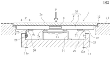
図2に示すように、装置本体10の内部、すなわち筐体部3の内部にフィードバック機構8が収納されている。フィードバック機構8が動作することによって、装置本体10にフィードバック力Fが与えられる。フィードバック機構8には、磁気吸引力を発揮するソレノイドが設けられ、ソレノイドの磁気駆動部と、磁気駆動部によって進退駆動されるプランジャの一方が、筐体部3に直接に固定され、他方がゴムなどの弾性部材を介して筐体部3に連結されている。このソレノイドにおけるプランジャの磁気吸引力によって、装置本体10に水平方向のフィードバック力Fが作用する。フィードバック力Fは、単発に発生される磁気吸引力に基づく衝撃力であり、またはフィードバック力Fは所定の周波数の振動力である。
As shown in FIG. 2, the
あるいは、フィードバック機構8は、ばね部材でF方向に移動自在に支持された錘である磁石と、磁石を力Fの発生方向へ往復移動させるコイルとで構成された振動発生機構であってもよい。または、力Fの方向と直交する回転軸を有するモータと、回転軸に固定されて質量が偏った錘とが設けられ、回転軸の回転力でF方向の振動力が発生するものであってもよい。
Alternatively, the
各図には、フィードバック機構8によって装置本体10に与えられるフィードバック力Fの向きと、パネル部2の表面である操作面4aが指で押されるときの押圧力Pの向きが矢印で示されている。ここでは、押圧力Pが、操作面4aに垂直に作用するものとする。
In each figure, the direction of the feedback force F applied to the apparatus
操作装置1は、車両のインストルメントパネル11に設置される。図1と図2に示すように、インストルメントパネル11に矩形状の開口部12が形成されており、装置本体10は、開口部12の内部に位置し、装置本体10の周縁部と、開口部12の内縁部との間には、フィードバック力Fの作用方向である水平方向と、これと直交する重力方向である垂直方向にわずかな隙間が形成されている。
The operating device 1 is installed on the
図2に示すように、インストルメントパネル11の開口部12の内部に基台13が設けられている。基台13は車体構造部の一部あるいはインストルメントパネル11の内部構造部である。基台13の前方で操作装置1が、複数の支持金属板20によって支持されている。支持金属板20は、ある程度の弾性を有する金属板で形成されており、例えば冷間圧延鋼板で形成されている。
As shown in FIG. 2, a
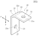
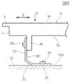
図3と図4(A)に示すように、支持金属板20は、板厚寸法と幅寸法とがほぼ均一な帯状の金属板を折り曲げて形成されている。支持金属板20は、第1の取付片21と中間板部22および第2の取付片23が連続して形成されている。第1の取付片21の板面21aと、第2の取付片23の板面23aは、設計上は互いに直角である。第1の取付片21の板面21aは、装置本体10に与えられるフィードバック力Fの作用方向に延びており、板面21aは操作面4aと平行である。第2の取付片23の板面23aは、操作面4aに与えられる押圧力Pの作用する方向に延びており、板面23aは操作面4aと垂直である。
As shown in FIGS. 3 and 4A, the supporting
第1の取付片21と中間板部22は、境界部24で折られ、中間板部22と第2の取付片23は境界部25で折られている。中間板部22の板面22aは平面であり、板面22aは、第1の取付片21の板面21aと第2の取付片23の板面23aの双方に対して傾斜している。
The
第1の取付片21には取付け穴26が形成され、第2の取付片23には取付け穴27が形成されている。
A mounting
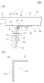
図2と図4(A)に示す実施の形態では、支持金属板20の第1の取付片21が、装置本体10の筐体部3の背面3aに設置され、固定ねじ28が取付け穴26に挿通されて、筐体部3に螺着されて固定されている。また、第2の取付片23が、基台13において操作面4aと垂直に形成された支持面13aに設置され、取付け穴27に挿入された固定ねじ29が支持台13に螺着されて、第2の取付片23が固定される。
In the embodiment shown in FIGS. 2 and 4A, the first mounting
図2に示すように、第2の取付片23は、操作面4aと垂直であり、全ての支持金属板20の第2の取付片23の板面23aは互いに平行である。また、第2の取付片23は、板厚方向がフィードバック力Fの作用方向(操作面4aと平行な方向)に向けられている。なお、第2の取付片23は、一部が平板でその板厚方向がフィードバック力Fの作用方向に向けられ、第2の取付片23の一部がコの字形状などに形成されていてもよい。
As shown in FIG. 2, the second mounting
図4(A)に示すように、支持金属板20の中間板部22は、筐体部3の背面3aに対して角度θを有して後方へ斜めに延びている。角度θは、30〜60度の範囲が好ましく、実施の形態では、θが45度である。
As shown in FIG. 4A, the
図2に示すように、基台13には検知支持部14が固定されており、検知支持部14に複数の検知部材15が取り付けられている。検知部材15は、力センサあるいは近接センサである。力センサは、装置本体10から押圧力Pを受けたときにその荷重で変形する弾性変形部と、この弾性変形部の変形を検知する歪みゲージとで構成されている。近接センサは、筐体部3の背面に設けられた磁石と、検知支持部14に設けられて前記磁石との距離の変化を検出する磁気センサとから構成される。
As shown in FIG. 2, a
あるいは、装置本体10のパネル部2に設けられた静電容量型の前記タッチセンサで、指の接触面積を検知し、この接触面積から押圧力Pを推測してもよい。この場合には、押圧力の大きさと指の接触面積の大きさとが比例するとは限らず、誤動作が生じる可能性があるので、本実施の形態のように、力センサや近接センサを用いて、装置本体10の変位を検出した方が確実に押圧操作を検出することができる。
Alternatively, the contact area of the finger may be detected by the capacitance type touch sensor provided on the
次に、前記操作装置1の動作について説明する。
この操作装置1は、装置本体10の内部に設けられた表示装置で表示される画像が、パネル部2に設けられたタッチセンサと表面パネルを透過して表示・操作領域4で前方から目視可能になる。操作装置1は、加飾領域5に設けられた操作部材6,7によって操作することができるが、さらに表示・操作領域4の表示画像を見ながら、表示・操作領域4の表面の操作面4aに指を触れることによっても入力操作を行うことができる。
Next, the operation of the controller device 1 will be described.
In this operation device 1, an image displayed on a display device provided inside the
この入力操作では、表示・操作領域4に表示された操作釦の画像に指を触れると、タッチセンサの座標検知出力によって、指がどの操作釦の画像に触れたかが判別される。その指で、操作面4aを押し込むと、支持金属板20の中間板部22が境界部24を支点としてα方向(図4(A)参照)へ倒れるように弾性変形し、装置本体10が押し込み方向へ移動でき、検知部材15でそのときの押圧力Pが検知される。制御部では、タッチセンサの検知出力から、表示・操作領域4に表示された画像のうちのどの操作釦の画像が操作されているのかを識別し、さらに検知部材15で押圧力が検知されたときに、押された操作釦の表示内容に基づく処理動作を開始する。
In this input operation, when a finger touches the image of the operation button displayed in the display / operation area 4, it is determined which operation button image the finger touches based on the coordinate detection output of the touch sensor. When the
検知部材15が押圧力Pを検知すると、制御部からフィードバック機構8に動作指令が出され、装置本体10に水平方向のフィードバック力Fが単発の力としてあるいは振動として与えられる。図4(A)に示すように、支持金属板20の第2の取付片23は、板厚方向がフィードバック力Fの作用方向に向けられているため、フィードバック力Fによって、第2の取付片23が板厚方向(β方向)へ曲げ変形できる。これにより、操作面4aがフィードバック力Fの付与方向へ動き、あるいは振動して、操作面4aに指を触れている操作者にフィードバック力Fが伝達される。
When the
図4(A)に示すように、支持金属板20は、フィードバック力Fの作用方向に対しては、主に第2の取付片23が板厚方向であるα方向へ曲げ変形する。一方で、装置本体10から押圧力Pが与えられたときは、中間板部22が境界部24を支点としてα方向へ倒れるように変形する。このとき、境界部24では、第1の取付片21と中間板部22との対向角度(i)が広がるように変形し、境界部25では、中間板部22と第2の取付片との対向角度(ii)が狭まるように変形する。したがって、装置本体10がフィードバック力Fに沿う方向へ動くときの支持金属板20の曲げ剛性(弾性係数)に対して、装置本体10が押圧力Pで押し込まれるときの支持金属板20の曲げ剛性(弾性係数)の方が十分に高くなる。
As shown in FIG. 4A, the
よって、装置本体10の操作面4aを指で押すときの抵抗力が十分に大きくなり、指に作用する反力で、操作者は指で十分強く押した操作感触を得ることができる。このとき、力センサなどの検知部材15によって、装置本体10の押圧力Pの作用方向へのわずかな動きを検知できるようにしている。一方で、フィードバック機構8が動作して、装置本体10に水平方向へのフィードバック力Fが作用したときは、装置本体10がその力の方向へ比較的動きやすくなっており、操作面4aに触れている指で、フィードバック力を十分に感じることができるようになる。
Therefore, the resistance force when the
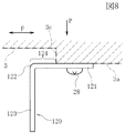
ただし、支持金属板20の力Fの方向への剛性は十分に高い値に維持することができる。図4(B)には比較例の支持金属板120が示されている。この支持金属板120は、第1の取付片121と第2の取付片123とが境界部122で直角に折り曲げられており、中間板部が設けられていない。比較例の支持金属板120を実施の形態の支持金属板20の代わりに使用することを想定したときに、実施の形態の支持金属板20と比較例の支持金属板120とで、フィードバック力Fが作用する方向での曲げ剛性(弾性係数)をほぼ同等にすることができる。
However, the rigidity of the supporting
すなわち、実施の形態の支持金属板20は、互いに垂直な第1の取付片21と第2の取付片23との間に、中間板部22を形成し、第1の取付片21と中間板部22との対向角度(i)および中間板部22と第2の取付片22との対向角度(ii)を鈍角にすることで、力Fの方向の曲げ剛性が、支持金属板120と同等となっている。よって、図4(A)に示す支持金属板20を用いて装置本体10を支持した構造では、車体振動などに対しては、比較例の支持金属板120を使用したのと同等の支持強度を発揮することができる。
That is, the
図5は、図3に示す支持金属板20の他の使用例を示している。
この使用例では、支持金属板20の第1の取付片21が、基台13の操作面4aと平行な表面13bに固定ねじ28で固定されている。装置本体10の筐体部3では、背面3aから後方に向けて固定突起3bが突出形成されており、第2の取付片23が固定突起3bの側面に設置されて固定ねじ29で固定されている。図5に示す使用例では、装置本体10に押圧力Pが与えられたときと、装置本体10にフィードバック力Fが作用したときとで、支持金属板20が図4(A)に示す使用例と同様に弾性変形し、図4(A)と図5で支持金属板20のF方向とP方向への曲げ剛性が同じである。
FIG. 5 shows another example of use of the supporting
In this usage example, the first mounting
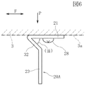
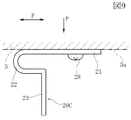
図6ないし図9は本発明の他の実施の形態における支持金属板の取付け構造を示している。 6 to 9 show a mounting structure of a supporting metal plate in another embodiment of the present invention.
図6に示す実施の形態では、支持金属板20Aの第1の取付片21と中間板部22との対向角度(iii)が鋭角となっている。図7に示す実施の形態では、支持金属板20Bの第1の取付片21と第2の取付片23との間が所定の曲率を有する湾曲面を介して連続しており、この湾曲面が中間板部22とされている。
In the embodiment shown in FIG. 6, the opposing angle (iii) between the first mounting
図6と図7に示す実施の形態では、装置本体10にフィードバック力Fが作用したときと押圧力Pが作用したときとで、支持金属板20A,20Bの曲げ剛性が図4(A)に示す実施の形態とほぼ同じである。
In the embodiment shown in FIGS. 6 and 7, the bending rigidity of the supporting
図8に示す実施の形態では、図4(B)に示したのと同じL字形状の支持金属板120が使用されている。筐体部3の背面3aに段差部3cが形成されている。第1の取付片121はその一部が背面3aに固定されているが、第1の取付片121のうちの中間部から境界部122までの一部が、段差部3cから突出して筐体部3から浮き上がっている。この浮き上がっている部分が、押圧力Pが作用したときに弾性変形可能な中間板部124になっている。
In the embodiment shown in FIG. 8, the same L-shaped supporting
図9に示す実施の形態では、支持金属板20Cの第1の取付片21と第2の取付片23との間のU字形状に曲げられた中間板部22が形成されており、装置本体10に押圧力Pが作用したときに、U字形状の中間板部22が弾性変形可能となっている。この実施の形態は、図4(A)に示す実施の形態に比較して、押圧力Pの作用方向の曲げ剛性がやや低くなっている。
In the embodiment shown in FIG. 9, an
1 操作装置
2 パネル部
3 筐体部
4 表示・操作領域
4a 操作面
5 加飾領域
8 フィードバック機構
10 装置本体
11 インストルメントパネル
12 開口部
15 検知部材
20 支持金属板
21 第1の取付片
22 中間板部
23 第2の取付片
24,25 境界部
F フィードバック力
P 押圧力
DESCRIPTION OF SYMBOLS 1
Claims (6)
それぞれの前記支持金属板は、前記装置本体と前記基台の一方に固定される第1の取付片と、他方に固定される第2の取付片と、前記第1の取付片と前記第2の取付片との間に位置する中間板部とが一体に形成されており、
前記第1の取付片の板面は、前記操作面とほぼ平行に設置され、前記第2の取付片の板面の少なくとも一部は前記操作面とほぼ垂直に設置されており、
前記フィードバック機構によって、前記装置本体に対して、前記第2の取付片の板面と交差する向きのフィードバック力が与えられ、前記操作面が押されたときに、前記中間板部が押圧方向へ弾性変形可能であることを特徴とする操作装置。 A device main body whose surface is an operation surface, a detection member for detecting that the operation surface is pressed, a feedback mechanism provided in the device main body, and a plurality of support metals for fixing the device main body to a base In an operating device provided with a plate,
Each of the supporting metal plates includes a first mounting piece fixed to one of the apparatus main body and the base, a second mounting piece fixed to the other, the first mounting piece, and the second mounting plate. The intermediate plate portion located between the mounting piece is integrally formed,
The plate surface of the first mounting piece is installed substantially parallel to the operation surface, and at least a part of the plate surface of the second mounting piece is installed substantially perpendicular to the operation surface,
By the feedback mechanism, a feedback force in a direction intersecting the plate surface of the second mounting piece is given to the apparatus main body, and when the operation surface is pressed, the intermediate plate portion moves in the pressing direction. An operating device that is elastically deformable.
Priority Applications (2)
| Application Number | Priority Date | Filing Date | Title |
|---|---|---|---|
| JP2016085836A JP6584360B2 (en) | 2016-04-22 | 2016-04-22 | Operating device having feedback mechanism |
| US15/462,075 US10338680B2 (en) | 2016-04-22 | 2017-03-17 | Operating apparatus having feedback mechanism |
Applications Claiming Priority (1)
| Application Number | Priority Date | Filing Date | Title |
|---|---|---|---|
| JP2016085836A JP6584360B2 (en) | 2016-04-22 | 2016-04-22 | Operating device having feedback mechanism |
Publications (2)
| Publication Number | Publication Date |
|---|---|
| JP2017194886A true JP2017194886A (en) | 2017-10-26 |
| JP6584360B2 JP6584360B2 (en) | 2019-10-02 |
Family
ID=60090175
Family Applications (1)
| Application Number | Title | Priority Date | Filing Date |
|---|---|---|---|
| JP2016085836A Active JP6584360B2 (en) | 2016-04-22 | 2016-04-22 | Operating device having feedback mechanism |
Country Status (2)
| Country | Link |
|---|---|
| US (1) | US10338680B2 (en) |
| JP (1) | JP6584360B2 (en) |
Cited By (6)
| Publication number | Priority date | Publication date | Assignee | Title |
|---|---|---|---|---|
| WO2019004049A1 (en) * | 2017-06-28 | 2019-01-03 | シャープ株式会社 | Input device |
| CN113778254A (en) * | 2020-06-09 | 2021-12-10 | 阿尔卑斯阿尔派株式会社 | Operating device |
| JP2022064693A (en) * | 2020-10-14 | 2022-04-26 | アルプスアルパイン株式会社 | Input device |
| JP2022097801A (en) * | 2020-12-21 | 2022-07-01 | 日本精機株式会社 | On-vehicle display device |
| JP2023047320A (en) * | 2021-09-24 | 2023-04-05 | エーエーシー アコースティック テクノロジーズ (シャンハイ) カンパニー リミテッド | Touch feedback device and electronic equipment |
| JP2023160207A (en) * | 2022-04-21 | 2023-11-02 | 株式会社東海理化電機製作所 | shift device |
Families Citing this family (2)
| Publication number | Priority date | Publication date | Assignee | Title |
|---|---|---|---|---|
| CN110620129B (en) | 2018-06-20 | 2022-02-01 | 京东方科技集团股份有限公司 | Display substrate, driving method thereof, display device and high-precision metal mask plate |
| CN110619813B (en) | 2018-06-20 | 2021-05-14 | 京东方科技集团股份有限公司 | Display substrate, driving method thereof, display device, and high-precision metal mask |
Citations (5)
| Publication number | Priority date | Publication date | Assignee | Title |
|---|---|---|---|---|
| EP2241955A1 (en) * | 2009-04-16 | 2010-10-20 | CN Innovations limited | Electronic touch screen device |
| JP2012068823A (en) * | 2010-09-22 | 2012-04-05 | Kyocera Corp | Display device with input function |
| JP2012094109A (en) * | 2010-09-28 | 2012-05-17 | Kyocera Corp | Display device with input function, and equipment |
| JP2014085932A (en) * | 2012-10-25 | 2014-05-12 | Kyocera Corp | Vibration device, and electronic apparatus |
| JP2014106584A (en) * | 2012-11-26 | 2014-06-09 | Tokai Rika Co Ltd | Input device |
Family Cites Families (4)
| Publication number | Priority date | Publication date | Assignee | Title |
|---|---|---|---|---|
| US7468573B2 (en) * | 2006-10-30 | 2008-12-23 | Motorola, Inc. | Method of providing tactile feedback |
| US8253698B2 (en) * | 2007-11-23 | 2012-08-28 | Research In Motion Limited | Tactile touch screen for electronic device |
| JP2013161384A (en) | 2012-02-08 | 2013-08-19 | Alps Electric Co Ltd | Input device |
| JP6955843B2 (en) * | 2016-03-25 | 2021-10-27 | 京セラ株式会社 | Actuator and tactile presentation device |
-
2016
- 2016-04-22 JP JP2016085836A patent/JP6584360B2/en active Active
-
2017
- 2017-03-17 US US15/462,075 patent/US10338680B2/en active Active
Patent Citations (5)
| Publication number | Priority date | Publication date | Assignee | Title |
|---|---|---|---|---|
| EP2241955A1 (en) * | 2009-04-16 | 2010-10-20 | CN Innovations limited | Electronic touch screen device |
| JP2012068823A (en) * | 2010-09-22 | 2012-04-05 | Kyocera Corp | Display device with input function |
| JP2012094109A (en) * | 2010-09-28 | 2012-05-17 | Kyocera Corp | Display device with input function, and equipment |
| JP2014085932A (en) * | 2012-10-25 | 2014-05-12 | Kyocera Corp | Vibration device, and electronic apparatus |
| JP2014106584A (en) * | 2012-11-26 | 2014-06-09 | Tokai Rika Co Ltd | Input device |
Cited By (12)
| Publication number | Priority date | Publication date | Assignee | Title |
|---|---|---|---|---|
| WO2019004049A1 (en) * | 2017-06-28 | 2019-01-03 | シャープ株式会社 | Input device |
| US10976584B2 (en) | 2017-06-28 | 2021-04-13 | Sharp Kabushiki Kaisha | Input device |
| CN113778254A (en) * | 2020-06-09 | 2021-12-10 | 阿尔卑斯阿尔派株式会社 | Operating device |
| EP3923117A1 (en) | 2020-06-09 | 2021-12-15 | Alps Alpine Co., Ltd. | Operation apparatus |
| US11400867B2 (en) | 2020-06-09 | 2022-08-02 | Alps Alpine Co., Ltd. | Operation apparatus |
| JP2022064693A (en) * | 2020-10-14 | 2022-04-26 | アルプスアルパイン株式会社 | Input device |
| JP7555229B2 (en) | 2020-10-14 | 2024-09-24 | アルプスアルパイン株式会社 | Input Devices |
| JP2022097801A (en) * | 2020-12-21 | 2022-07-01 | 日本精機株式会社 | On-vehicle display device |
| JP7552339B2 (en) | 2020-12-21 | 2024-09-18 | 日本精機株式会社 | In-vehicle display device |
| JP2023047320A (en) * | 2021-09-24 | 2023-04-05 | エーエーシー アコースティック テクノロジーズ (シャンハイ) カンパニー リミテッド | Touch feedback device and electronic equipment |
| JP7472216B2 (en) | 2021-09-24 | 2024-04-22 | エーエーシー アコースティック テクノロジーズ (シャンハイ) カンパニー リミテッド | Touch feedback device and electronic device |
| JP2023160207A (en) * | 2022-04-21 | 2023-11-02 | 株式会社東海理化電機製作所 | shift device |
Also Published As
| Publication number | Publication date |
|---|---|
| US20170308167A1 (en) | 2017-10-26 |
| US10338680B2 (en) | 2019-07-02 |
| JP6584360B2 (en) | 2019-10-02 |
Similar Documents
| Publication | Publication Date | Title |
|---|---|---|
| JP6584360B2 (en) | Operating device having feedback mechanism | |
| US20200125174A1 (en) | Tactile feedback device and electronic device equipped with said tactile feedback device | |
| US20180081483A1 (en) | Trackpad integration in an electronic device | |
| WO2011024434A1 (en) | Tactile sensation imparting device and control method of tactile sensation imparting device | |
| WO2011024435A1 (en) | Tactile sensation imparting device and control method of tactile sensation imparting device | |
| US20190107889A1 (en) | Input device | |
| JP2015536547A (en) | Operating device for vehicle parts | |
| WO2019017284A1 (en) | Input device | |
| EP3570143B1 (en) | Responsive force generator and vehicle-mounted display device including responsive force generator | |
| JP5784283B2 (en) | Tactile sensation presentation apparatus and control method for tactile sensation presentation apparatus | |
| JP5960589B2 (en) | Touch screen device | |
| EP3444948A1 (en) | Response force generation device | |
| US11377043B2 (en) | Operating device | |
| JP4808804B2 (en) | Input device | |
| JP7514849B2 (en) | Vehicle operation unit | |
| JP2019075022A (en) | Display device | |
| CN112946939A (en) | Display device | |
| EP3923117B1 (en) | Operation apparatus | |
| JP6284946B2 (en) | Capacitive sensor for detecting the relative movement of two adjacent bodies | |
| JP4838891B2 (en) | Input device | |
| JP2022043469A (en) | Operation device | |
| JP5388989B2 (en) | Input device and control method of input device | |
| JP2022164198A (en) | Display device with touch panel | |
| JP2021146238A (en) | Operation device | |
| JPWO2019092815A1 (en) | Capacitance change detection structure and electronic device having the same |
Legal Events
| Date | Code | Title | Description |
|---|---|---|---|
| A621 | Written request for application examination |
Free format text: JAPANESE INTERMEDIATE CODE: A621 Effective date: 20181225 |
|
| A977 | Report on retrieval |
Free format text: JAPANESE INTERMEDIATE CODE: A971007 Effective date: 20190826 |
|
| TRDD | Decision of grant or rejection written | ||
| A01 | Written decision to grant a patent or to grant a registration (utility model) |
Free format text: JAPANESE INTERMEDIATE CODE: A01 Effective date: 20190903 |
|
| A61 | First payment of annual fees (during grant procedure) |
Free format text: JAPANESE INTERMEDIATE CODE: A61 Effective date: 20190903 |
|
| R150 | Certificate of patent or registration of utility model |
Ref document number: 6584360 Country of ref document: JP Free format text: JAPANESE INTERMEDIATE CODE: R150 |