JP2017194913A - Probe information processing server, probe vehicle, and probe information processing method - Google Patents

Probe information processing server, probe vehicle, and probe information processing method Download PDF

Info

Publication number
JP2017194913A
JP2017194913A JP2016086213A JP2016086213A JP2017194913A JP 2017194913 A JP2017194913 A JP 2017194913A JP 2016086213 A JP2016086213 A JP 2016086213A JP 2016086213 A JP2016086213 A JP 2016086213A JP 2017194913 A JP2017194913 A JP 2017194913A
Authority
JP
Japan
Prior art keywords
probe
vehicle
information
driving
probe vehicle
Prior art date
Legal status (The legal status is an assumption and is not a legal conclusion. Google has not performed a legal analysis and makes no representation as to the accuracy of the status listed.)
Granted
Application number
JP2016086213A
Other languages
Japanese (ja)
Other versions
JP6896374B2 (en
Inventor
鈴木 美彦
Yoshihiko Suzuki
美彦 鈴木
雄介 高橋
Yusuke Takahashi
雄介 高橋
佐藤 俊雄
Toshio Sato
俊雄 佐藤
上野 秀樹
Hideki Ueno
秀樹 上野
浩 堺
Hiroshi Sakai
浩 堺
Current Assignee (The listed assignees may be inaccurate. Google has not performed a legal analysis and makes no representation or warranty as to the accuracy of the list.)
Toshiba Corp
Original Assignee
Toshiba Corp
Priority date (The priority date is an assumption and is not a legal conclusion. Google has not performed a legal analysis and makes no representation as to the accuracy of the date listed.)
Filing date
Publication date
Application filed by Toshiba Corp filed Critical Toshiba Corp
Priority to JP2016086213A priority Critical patent/JP6896374B2/en
Publication of JP2017194913A publication Critical patent/JP2017194913A/en
Application granted granted Critical
Publication of JP6896374B2 publication Critical patent/JP6896374B2/en
Active legal-status Critical Current
Anticipated expiration legal-status Critical

Links

Images

Landscapes

  • Instructional Devices (AREA)
  • Traffic Control Systems (AREA)

Abstract

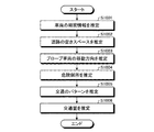
【課題】交通情報の推定精度を向上させるプローブ情報処理サーバ、プローブ車両、およびプローブ情報処理方法を提供する。【解決手段】実施形態のプローブ情報処理サーバは、受信部と、推定部と、生成部と、送信部と、を備える。受信部は、プローブ車両から、当該プローブ車両の走行に関する情報でありかつプローブ車両の走行位置を含むプローブ情報を受信する。推定部は、受信したプローブ情報に基づいて、地図上における道路の各区間の交通情報を推定する。生成部は、運転制御対象のプローブ車両が走行する区間の交通情報に対応する推奨走行方法と、運転制御対象のプローブ車両から受信したプローブ情報に基づく当該プローブ車両の走行方法との差分に基づいて、当該差分を減少させることを指示する運転制御情報を生成する。送信部は、生成した運転制御情報を運転制御対象のプローブ車両に送信する。【選択図】図7PROBLEM TO BE SOLVED: To provide a probe information processing server, a probe vehicle, and a probe information processing method for improving the estimation accuracy of traffic information. A probe information processing server according to an embodiment includes a receiving unit, an estimating unit, a generating unit, and a transmitting unit. The receiving unit receives from the probe vehicle the probe information including the traveling position of the probe vehicle and the information regarding the traveling of the probe vehicle. The estimation unit estimates the traffic information of each section of the road on the map based on the received probe information. The generation unit is based on the difference between the recommended driving method corresponding to the traffic information of the section in which the probe vehicle subject to driving control travels and the driving method of the probe vehicle based on the probe information received from the probe vehicle subject to driving control. , Generates operation control information instructing to reduce the difference. The transmission unit transmits the generated driving control information to the probe vehicle subject to driving control. [Selection diagram] FIG. 7

Description

本発明の実施形態は、プローブ情報処理サーバ、プローブ車両、およびプローブ情報処理方法に関する。   Embodiments described herein relate generally to a probe information processing server, a probe vehicle, and a probe information processing method.

プローブ車両により計測される車間距離等のプローブ情報に基づいて、地図上の各道路の交通情報を推定する技術がある。   There is a technique for estimating traffic information of each road on a map based on probe information such as an inter-vehicle distance measured by a probe vehicle.

特開2006−31422号公報JP 2006-31422 A 特開2002−251698号公報JP 2002-251698 A 特開2008−15561号公報JP 2008-15561 A

しかしながら、このような従来技術においては、プローブ車両の走行方法(例えば、車間距離の取り方、加減速の方法、車線の選定方法)にばらつきが生じると、交通情報の推定精度が低下する。   However, in such a conventional technique, when the traveling method of the probe vehicle (for example, how to obtain the inter-vehicle distance, the acceleration / deceleration method, the lane selection method) varies, the estimation accuracy of the traffic information decreases.

実施形態のプローブ情報処理サーバは、受信部と、推定部と、生成部と、送信部と、を備える。受信部は、プローブ車両から、当該プローブ車両の走行に関する情報でありかつプローブ車両の走行位置を含むプローブ情報を受信する。推定部は、受信したプローブ情報に基づいて、地図上における道路の各区間の交通情報を推定する。生成部は、運転制御対象のプローブ車両が走行する区間の交通情報に対応する推奨走行方法と、運転制御対象のプローブ車両から受信したプローブ情報に基づく当該プローブ車両の走行方法との差分に基づいて、当該差分を減少させることを指示する運転制御情報を生成する。送信部は、生成した運転制御情報を運転制御対象のプローブ車両に送信する。   The probe information processing server of the embodiment includes a reception unit, an estimation unit, a generation unit, and a transmission unit. The receiving unit receives, from the probe vehicle, probe information that is information related to the travel of the probe vehicle and includes the travel position of the probe vehicle. The estimation unit estimates traffic information of each section of the road on the map based on the received probe information. The generation unit is based on a difference between a recommended traveling method corresponding to traffic information of a section in which the probe vehicle to be controlled by driving and a traveling method of the probe vehicle based on the probe information received from the probe vehicle to be controlled by driving. Then, operation control information for instructing to decrease the difference is generated. A transmission part transmits the produced | generated driving control information to the probe vehicle of driving control object.

図1は、本実施形態にかかるプローブ情報処理システムの構成の一例を示す図である。FIG. 1 is a diagram illustrating an example of a configuration of a probe information processing system according to the present embodiment. 図2は、本実施形態にかかるプローブ情報処理システムが有するプローブ車両の構成の一例を示す図である。FIG. 2 is a diagram illustrating an example of a configuration of a probe vehicle included in the probe information processing system according to the present embodiment. 図3は、本実施形態にかかるプローブ情報処理システムが有するプローブ車両のコックピットの構成の一例を示す図である。FIG. 3 is a diagram illustrating an example of the configuration of the cockpit of the probe vehicle included in the probe information processing system according to the present embodiment. 図4は、本実施形態にかかるプローブ情報処理システムのプローブ車両が有する制御装置のハードウェア構成の一例を示す図である。FIG. 4 is a diagram illustrating an example of a hardware configuration of a control device included in the probe vehicle of the probe information processing system according to the present embodiment. 図5は、本実施形態にかかるプローブ情報処理システムのプローブ車両による車頭間距離の算出処理の一例を説明するための図である。FIG. 5 is a diagram for explaining an example of the calculation process of the inter-vehicle head distance by the probe vehicle of the probe information processing system according to the present embodiment. 図6は、本実施形態にかかるプローブ情報処理システムのプローブ車両による車頭間距離の算出処理の流れの一例を示すフローチャートである。FIG. 6 is a flowchart showing an example of the flow of calculation processing of the inter-head distance by the probe vehicle of the probe information processing system according to the present embodiment. 図7は、本実施形態にかかるプローブ情報処理サーバにおける交通情報の推定処理および運転制御情報の生成処理の一例を説明するための図である。FIG. 7 is a diagram for explaining an example of traffic information estimation processing and driving control information generation processing in the probe information processing server according to the present embodiment. 図8は、本実施形態にかかるプローブ情報処理サーバのハードウェア構成の一例を示す図である。FIG. 8 is a diagram illustrating an example of a hardware configuration of the probe information processing server according to the present embodiment. 図9は、本実施形態にかかるプローブ情報処理サーバにおける交通情報の推定処理および運転制御情報の生成処理の流れの一例を示すフローチャートである。FIG. 9 is a flowchart illustrating an example of the flow of traffic information estimation processing and driving control information generation processing in the probe information processing server according to the present embodiment. 図10は、本実施形態にかかるプローブ情報処理サーバによる交通情報の推定処理の流れの一例を示すフローチャートである。FIG. 10 is a flowchart illustrating an example of a flow of traffic information estimation processing by the probe information processing server according to the present embodiment. 図11は、本実施形態にかかるプローブ車両による個別車両運転特性の特定処理の流れの一例を示すフローチャートである。FIG. 11 is a flowchart showing an example of the flow of individual vehicle driving characteristic specifying processing by the probe vehicle according to the present embodiment. 図12は、本実施形態にかかるプローブ情報処理システムにおけるプローブ車両とプローブ情報処理サーバ間における各種情報の送受信処理の一例を説明するための図である。FIG. 12 is a diagram for explaining an example of various information transmission / reception processes between the probe vehicle and the probe information processing server in the probe information processing system according to the present embodiment. 図13は、本実施形態にかかるプローブ車両の機能構成の一例を示すブロック図である。FIG. 13 is a block diagram illustrating an example of a functional configuration of the probe vehicle according to the present embodiment. 図14Aは、本実施形態にかかるプローブ車両の運転手による外界の認識状況を推定する処理の流れの一例を示すフローチャートである。FIG. 14A is a flowchart illustrating an example of a flow of processing for estimating the recognition status of the outside world by the driver of the probe vehicle according to the present embodiment. 図14Bは、本実施形態にかかるプローブ車両の運転手の視線方向を検出する処理の一例を説明するための図である。FIG. 14B is a diagram for explaining an example of a process of detecting the line-of-sight direction of the driver of the probe vehicle according to the present embodiment. 図15は、本実施形態にかかるプローブ車両による外界のオブジェクトの検出処理の流れの一例を示すフローチャートである。FIG. 15 is a flowchart illustrating an example of a flow of processing for detecting an object in the outside world by the probe vehicle according to the present embodiment. 図16は、本実施形態にかかるプローブ車両による撮像画像データを記憶する処理の流れの一例を示すフローチャートである。FIG. 16 is a flowchart illustrating an example of a flow of processing for storing captured image data by the probe vehicle according to the present embodiment. 図17は、本実施形態にかかるプローブ車両による高次特徴量を記憶する処理の一例を説明するための図である。FIG. 17 is a diagram for explaining an example of processing for storing higher-order feature values by the probe vehicle according to the present embodiment. 図18は、本実施形態にかかるプローブ車両による運転操作の検出処理の流れの一例を示すフローチャートである。FIG. 18 is a flowchart illustrating an example of a flow of detection processing of a driving operation by the probe vehicle according to the present embodiment. 図19は、本実施形態にかかるプローブ車両による運転操作の検出処理の一例を説明するための図である。FIG. 19 is a diagram for explaining an example of the driving operation detection process by the probe vehicle according to the present embodiment. 図20は、本実施形態にかかるプローブ車両による個別車両運転特性の検出処理の流れの一例を示すフローチャートである。FIG. 20 is a flowchart showing an example of the flow of the individual vehicle driving characteristic detection process by the probe vehicle according to the present embodiment.

以下、添付の図面を用いて、本実施形態にかかるプローブ情報処理サーバ、プローブ車両、およびプローブ情報処理方法を適用したプローブ情報処理システムについて説明する。   Hereinafter, a probe information processing system to which a probe information processing server, a probe vehicle, and a probe information processing method according to the present embodiment are applied will be described with reference to the accompanying drawings.

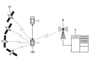
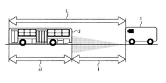
図1は、本実施形態にかかるプローブ情報処理システムの構成の一例を示す図である。図1に示すように、本実施形態にかかるプローブ情報処理システムは、プローブ車両1と、先行車両2と、GPS(Global Positioning System)衛星STと、基地局Bと、プローブ情報処理サーバSと、を有する。プローブ車両1は、当該プローブ車両1の周囲(例えば、先行車両2)を撮像する。先行車両2は、プローブ車両1の前方を走行する車両である。   FIG. 1 is a diagram illustrating an example of a configuration of a probe information processing system according to the present embodiment. As shown in FIG. 1, the probe information processing system according to this embodiment includes a probe vehicle 1, a preceding vehicle 2, a GPS (Global Positioning System) satellite ST, a base station B, a probe information processing server S, Have The probe vehicle 1 images the periphery of the probe vehicle 1 (for example, the preceding vehicle 2). The preceding vehicle 2 is a vehicle that travels in front of the probe vehicle 1.

本実施形態では、プローブ車両1は、後述する携帯端末205(図3参照)を介して基地局Bと無線通信する制御装置100を有する。本実施形態では、制御装置100は、携帯端末205を介して基地局Bと無線通信しているが、これに限定するものではなく、携帯端末205を介さずに、基地局Bと無線通信可能とする通信インターフェースを備えていても良い。制御装置100は、プローブ車両1に搭載され、当該プローブ車両1を制御する。また、制御装置100は、プローブ車両1の走行に関する情報であって、少なくともプローブ車両1の走行位置を含むプローブ情報を取得する。   In the present embodiment, the probe vehicle 1 includes a control device 100 that wirelessly communicates with the base station B via a portable terminal 205 (see FIG. 3) described later. In the present embodiment, the control device 100 wirelessly communicates with the base station B via the mobile terminal 205, but is not limited thereto, and can wirelessly communicate with the base station B without using the mobile terminal 205. A communication interface may be provided. The control device 100 is mounted on the probe vehicle 1 and controls the probe vehicle 1. In addition, the control device 100 obtains probe information that is information related to the traveling of the probe vehicle 1 and includes at least the traveling position of the probe vehicle 1.

例えば、制御装置100は、プローブ車両1と先行車両2との車間距離を所定の周期(例えば、数秒周期)で取得する。そして、制御装置100は、取得した車間距離および先行車両2の車長に基づいて、プローブ車両1と先行車両2との車頭間距離を算出する。また、制御装置100は、GPS衛星STから受信するGPS信号に基づいて、プローブ車両1の走行位置を示す位置情報を取得する。例えば、位置情報は、プローブ車両1の走行位置の緯度および経度、時刻等を含むGPS情報である。また、制御装置100は、プローブ車両1の走行速度を取得する。   For example, the control device 100 acquires the inter-vehicle distance between the probe vehicle 1 and the preceding vehicle 2 at a predetermined cycle (for example, a cycle of several seconds). Then, the control device 100 calculates the inter-head distance between the probe vehicle 1 and the preceding vehicle 2 based on the acquired inter-vehicle distance and the vehicle length of the preceding vehicle 2. Moreover, the control apparatus 100 acquires the positional information which shows the traveling position of the probe vehicle 1 based on the GPS signal received from GPS satellite ST. For example, the position information is GPS information including the latitude and longitude of the travel position of the probe vehicle 1 and the time. In addition, the control device 100 acquires the traveling speed of the probe vehicle 1.

そして、制御装置100は、車間距離、先行車両2の車種(例えば、普通車、大型車)、車頭間距離、位置情報、走行速度、先行車両2の移動方向、プローブ車両1と先行車両2との相対速度等をプローブ情報として、基地局Bを介して、プローブ情報処理サーバSに送信する。また、制御装置100は、プローブ情報に基づいて、地図上の道路を分割した区間のうち、プローブ車両1が走行する区間の交通情報(例えば、車両の密度、車両の流量など)を推定可能である場合、当該推定した交通情報をプローブ情報に含めて、プローブ情報処理サーバSに送信しても良い。   The control device 100 then determines the distance between the vehicles, the vehicle type of the preceding vehicle 2 (for example, a normal vehicle, a large vehicle), the distance between the heads, the position information, the traveling speed, the moving direction of the preceding vehicle 2, the probe vehicle 1 and the preceding vehicle 2. Is transmitted as probe information to the probe information processing server S via the base station B. Further, the control device 100 can estimate traffic information (for example, vehicle density, vehicle flow rate, etc.) of a section where the probe vehicle 1 travels among sections obtained by dividing the road on the map based on the probe information. In some cases, the estimated traffic information may be included in the probe information and transmitted to the probe information processing server S.

また、制御装置100は、プローブ車両1の運転の癖、安全運転、環境負荷、および移動効率のうち少なくとも1つに関する運転特性(以下、個別車両運転特性と言う)をプローブ情報に含めて、プローブ情報処理サーバSに送信する。本実施形態では、個別車両運転特性には、安全運転度、エコ運転度、および移動効率のうち少なくとも1つを含む。安全運転度は、プローブ車両1の安全運転度の度合いを示す。エコ運転度は、プローブ車両1の走行による環境負荷の度合いを示す。移動効率は、プローブ車両1の所定時間当たりの移動距離を示す。また、制御装置100は、基地局Bを介して、プローブ情報処理サーバSから運転制御情報を受信する。ここで、運転制御情報は、プローブ車両1を制御する情報であり、詳細は後述する。   In addition, the control device 100 includes, in the probe information, driving characteristics (hereinafter referred to as individual vehicle driving characteristics) relating to at least one of the driving habits of the probe vehicle 1, safe driving, environmental load, and movement efficiency. It transmits to the information processing server S. In the present embodiment, the individual vehicle driving characteristics include at least one of a safe driving degree, an eco driving degree, and a movement efficiency. The safe driving degree indicates the degree of the safe driving degree of the probe vehicle 1. The eco-driving degree indicates the degree of environmental load due to traveling of the probe vehicle 1. The movement efficiency indicates a movement distance of the probe vehicle 1 per predetermined time. Further, the control device 100 receives the operation control information from the probe information processing server S via the base station B. Here, the driving control information is information for controlling the probe vehicle 1 and will be described in detail later.

GPS衛星STは、時刻等を含むGPS信号を地上に送信する。基地局Bは、プローブ車両1と無線通信可能であり、プローブ車両1から送信されたプローブ情報を、プローブ情報処理サーバSに転送する。プローブ情報処理サーバSは、基地局Bを介してプローブ車両1から受信したプローブ情報等に基づいて、交通情報の推定や運転制御情報の生成等を行う。本実施形態では、運転制御情報は、速度指示、車間指示、車線指示などを含む。速度指示は、プローブ車両1の走行速度を指示する。本実施形態では、速度指示は、減速、現状維持、または加速を指示する。車間指示は、プローブ車両1の先行車両2との車間距離または車頭間距離を指示する。本実施形態では、車間指示は、短縮、現状維持、または延長を指示する。車線指示は、プローブ車両1が走行する車線を指示する。本実施形態では、車線指示は、左車線に変更、現状維持、または右車線に変更を指示する。   The GPS satellite ST transmits a GPS signal including time and the like to the ground. The base station B can communicate wirelessly with the probe vehicle 1 and transfers the probe information transmitted from the probe vehicle 1 to the probe information processing server S. The probe information processing server S estimates traffic information and generates driving control information based on probe information received from the probe vehicle 1 via the base station B. In the present embodiment, the driving control information includes a speed instruction, an inter-vehicle instruction, a lane instruction, and the like. The speed instruction indicates the traveling speed of the probe vehicle 1. In the present embodiment, the speed instruction instructs deceleration, maintenance of current conditions, or acceleration. The inter-vehicle instruction indicates the inter-vehicle distance or the inter-vehicle head distance between the probe vehicle 1 and the preceding vehicle 2. In the present embodiment, the inter-vehicle instruction instructs shortening, maintaining the current state, or extending. The lane instruction indicates a lane in which the probe vehicle 1 travels. In this embodiment, the lane instruction instructs to change to the left lane, maintain the current state, or change to the right lane.

例えば、プローブ情報処理サーバSは、運転制御対象のプローブ車両1から受信したプローブ情報が含む車頭間距離と、推奨走行方法が含む車頭間距離との差分を求める。ここで、推奨走行方法は、プローブ車両1の走行位置が属する区間の交通情報に応じた走行方法である。例えば、推奨走行方法は、プローブ車両1に推奨される車頭間距離等を含む。そして、プローブ情報処理サーバSは、受信したプローブ情報が含む車頭間距離が、推奨走行方法が含む車頭間距離よりも短い場合、車頭間距離の延長を指示する車間指示を含む運転制御情報を、基地局Bを介して、プローブ車両1に送信する。すなわち、プローブ情報処理サーバSは、運転制御対象のプローブ車両1の走行方法と推奨走行方法との差分に基づいて、当該差分を減少させることを指示する運転制御情報を生成する。   For example, the probe information processing server S obtains a difference between the inter-head distance included in the probe information received from the probe vehicle 1 to be operated and the inter-head distance included in the recommended travel method. Here, the recommended travel method is a travel method according to traffic information of a section to which the travel position of the probe vehicle 1 belongs. For example, the recommended traveling method includes a head-to-head distance recommended for the probe vehicle 1. And the probe information processing server S, when the inter-vehicle distance included in the received probe information is shorter than the inter-vehicle distance included in the recommended driving method, the driving control information including the inter-vehicle instruction instructing to extend the inter-vehicle distance, It transmits to the probe vehicle 1 via the base station B. That is, the probe information processing server S generates driving control information instructing to reduce the difference based on the difference between the driving method of the probe vehicle 1 to be driving controlled and the recommended driving method.

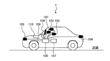
図2は、本実施形態にかかるプローブ情報処理システムが有するプローブ車両の構成の一例を示す図である。図2に示すように、プローブ車両1は、制御装置100と、カメラ101〜104と、レーダ105と、ECU(Engine Control Unit)107と、表示部108と、スピーカ109と、通信機器110と、を有する。カメラ101〜104は、プローブ車両1に搭載される車載カメラであり、撮像により得られた撮像画像データをフレーム単位で制御装置100に出力する。カメラ101は、予め設定された高さ、俯角、回転角等の撮像条件に従って設けられ、プローブ車両1の車内を撮像可能である。カメラ102〜104は、予め設定された高さ、俯角、回転角等の撮像条件に従って設けられ、プローブ車両1の車外を撮像可能である。レーダ105は、プローブ車両1の外部に対して電波を照射し、その反射波を測定することによって、プローブ車両1の外部に存在するオブジェクト(障害物や歩行者など)までの距離を測定する。そして、レーダ105は、測定した距離を示す距離情報を制御装置100に出力する。   FIG. 2 is a diagram illustrating an example of a configuration of a probe vehicle included in the probe information processing system according to the present embodiment. As shown in FIG. 2, the probe vehicle 1 includes a control device 100, cameras 101 to 104, a radar 105, an ECU (Engine Control Unit) 107, a display unit 108, a speaker 109, a communication device 110, Have The cameras 101 to 104 are in-vehicle cameras mounted on the probe vehicle 1 and output captured image data obtained by imaging to the control device 100 in units of frames. The camera 101 is provided in accordance with imaging conditions such as a preset height, depression angle, and rotation angle, and can image the interior of the probe vehicle 1. The cameras 102 to 104 are provided according to imaging conditions such as a preset height, depression angle, and rotation angle, and are capable of imaging the outside of the probe vehicle 1. The radar 105 measures the distance to an object (such as an obstacle or a pedestrian) existing outside the probe vehicle 1 by irradiating the outside of the probe vehicle 1 with radio waves and measuring the reflected wave. Then, the radar 105 outputs distance information indicating the measured distance to the control device 100.

制御装置100は、カメラ101〜104から出力される撮像画像データに基づいて、先行車両2との車間距離を検出する。そして、制御装置100は、レーダ105から出力される距離情報や先行車両2との車間距離の検出結果に基づいて、安全運転の支援に必要な情報(以下、警告情報と言う)を表示部108に表示したり、当該警告情報を表す音声をスピーカ109から出力したりする。また、制御装置100は、カメラ101〜104から出力される撮像画像データに基づいて、プローブ車両1の自動ブレーキの作動が必要であることを検出した場合、ECU107に対して、自動ブレーキの作動を指示する運転アシスト情報を送信する。ECU107は、制御装置100から運転アシスト情報を受信した場合に、自動ブレーキを作動させて、プローブ車両1を停止させる。   The control device 100 detects the inter-vehicle distance from the preceding vehicle 2 based on the captured image data output from the cameras 101 to 104. Based on the distance information output from the radar 105 and the detection result of the inter-vehicle distance from the preceding vehicle 2, the control device 100 displays information (hereinafter referred to as warning information) necessary for assisting safe driving. Or a sound representing the warning information is output from the speaker 109. Further, when the control device 100 detects that the automatic brake operation of the probe vehicle 1 is necessary based on the captured image data output from the cameras 101 to 104, the control device 100 causes the ECU 107 to operate the automatic brake. The driving assistance information to be instructed is transmitted. When the ECU 107 receives the driving assistance information from the control device 100, the ECU 107 activates the automatic brake to stop the probe vehicle 1.

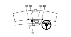
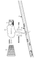
図3は、本実施形態にかかるプローブ情報処理システムが有するプローブ車両のコックピットの構成の一例を示す図である。図3に示すように、プローブ車両1のコックピットには、制御装置100と、カメラ202,203と、GPS(Global Positioning System)アンテナ204と、携帯端末205と、が設けられる。カメラ202,203は、カメラ102に含まれ、プローブ車両1の前方を走行する先行車両2を、互いに異なるアングルから撮像可能に設けられている。本実施形態では、カメラ202,203は、センターコンソールを挟んで左右対称に設けられている。   FIG. 3 is a diagram illustrating an example of the configuration of the cockpit of the probe vehicle included in the probe information processing system according to the present embodiment. As shown in FIG. 3, the cockpit of the probe vehicle 1 is provided with a control device 100, cameras 202 and 203, a GPS (Global Positioning System) antenna 204, and a mobile terminal 205. The cameras 202 and 203 are included in the camera 102 and are provided so that the preceding vehicle 2 traveling in front of the probe vehicle 1 can be imaged from different angles. In the present embodiment, the cameras 202 and 203 are provided symmetrically with respect to the center console.

制御装置100は、カメラ202,203それぞれの撮像により得られた撮像画像データに基づいて、カメラ202,203のアングルの視差を求める。そして、制御装置100は、求めた視差を用いて、プローブ車両1の先端から先行車両2の後端までの距離である車間距離を算出する。本実施形態では、制御装置100は、カメラ202,203の撮像により得られた撮像画像を用いて、車間距離を算出しているが、これに限定するものではなく、ステレオカメラまたは単眼カメラの撮像により得られた画像を用いて、車間距離を算出しても良い。   The control device 100 obtains the parallax of the angles of the cameras 202 and 203 based on the captured image data obtained by capturing the images of the cameras 202 and 203, respectively. And the control apparatus 100 calculates the inter-vehicle distance which is the distance from the front-end | tip of the probe vehicle 1 to the rear end of the preceding vehicle 2 using the calculated | required parallax. In the present embodiment, the control device 100 calculates the inter-vehicle distance using the captured images obtained by the imaging of the cameras 202 and 203. However, the present invention is not limited to this, and the imaging of a stereo camera or a monocular camera is performed. The inter-vehicle distance may be calculated using the image obtained by the above.

GPSアンテナ204は、プローブ車両1の位置を取得するために、GPS衛星STから発信されるGPS信号を受信する。携帯端末205は、基地局Bを介して、プローブ情報処理サーバSとデータ通信を行う。例えば、携帯端末205は、プローブ情報処理サーバSから受信した運転制御情報に基づいて、音声等を出力して、プローブ車両1の搭乗者(例えば、運転手)に対して運転制御情報を通知する。本実施形態では、携帯端末205は、スマートフォンやタブレット端末等により構成されるが、プローブ情報処理サーバSと通信可能な装置であれば、これに限定するものではない。   The GPS antenna 204 receives a GPS signal transmitted from the GPS satellite ST in order to acquire the position of the probe vehicle 1. The portable terminal 205 performs data communication with the probe information processing server S via the base station B. For example, the mobile terminal 205 outputs a voice or the like based on the driving control information received from the probe information processing server S, and notifies the driving control information to the passenger (for example, the driver) of the probe vehicle 1. . In the present embodiment, the mobile terminal 205 is configured by a smartphone, a tablet terminal, or the like, but is not limited to this as long as it is a device that can communicate with the probe information processing server S.

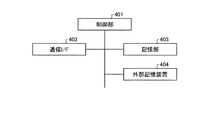
図4は、本実施形態にかかるプローブ情報処理システムのプローブ車両が有する制御装置のハードウェア構成の一例を示す図である。図4に示すように、制御装置100は、制御部401と、通信I/F402と、記憶部403と、外部記憶装置404と、を有する。制御部401は、制御装置100全体を制御する。本実施形態では、制御部401は、MPU(Micro Processing Unit)等を含むマイクロコンピュータで構成される。   FIG. 4 is a diagram illustrating an example of a hardware configuration of a control device included in the probe vehicle of the probe information processing system according to the present embodiment. As illustrated in FIG. 4, the control device 100 includes a control unit 401, a communication I / F 402, a storage unit 403, and an external storage device 404. The control unit 401 controls the entire control device 100. In the present embodiment, the control unit 401 is composed of a microcomputer including an MPU (Micro Processing Unit) and the like.

具体的には、制御部401(送信部の一例)は、プローブ情報をプローブ情報処理サーバSに送信する。また、制御部401(受信部の一例)は、プローブ情報処理サーバSから運転制御情報を受信する。本実施形態では、制御部401は、携帯端末205を制御して、モバイル回線等を介して、プローブ情報処理サーバSとの間でプローブ情報および運転制御情報を送受信する。さらに、制御部401は、プローブ情報処理サーバSから受信した運転制御情報を、携帯端末205から音声として出力等することによって、当該運転制御情報に従って、プローブ車両1の走行を制御する。本実施形態では、制御部401は、携帯端末205から音声を出力することにより、プローブ車両1の走行を制御しているが、これに限定するものではない。例えば、制御部401は、プローブ情報処理サーバSから受信した運転制御情報に基づいて、運転アシスト情報を生成し、当該運転アシスト情報をECU107に送信して、自動ブレーキ等を作動させてプローブ車両1を減速させたり停止させたりすることによって、プローブ車両1の走行を制御しても良い。   Specifically, the control unit 401 (an example of a transmission unit) transmits probe information to the probe information processing server S. The control unit 401 (an example of a receiving unit) receives operation control information from the probe information processing server S. In the present embodiment, the control unit 401 controls the portable terminal 205 to transmit / receive probe information and operation control information to / from the probe information processing server S via a mobile line or the like. Further, the control unit 401 controls the traveling of the probe vehicle 1 according to the driving control information by outputting the driving control information received from the probe information processing server S as a voice from the portable terminal 205. In the present embodiment, the control unit 401 controls the traveling of the probe vehicle 1 by outputting sound from the portable terminal 205, but is not limited to this. For example, the control unit 401 generates driving assist information based on the driving control information received from the probe information processing server S, transmits the driving assist information to the ECU 107, and activates an automatic brake or the like to operate the probe vehicle 1. The traveling of the probe vehicle 1 may be controlled by slowing down or stopping the vehicle.

通信I/F402は、カメラ101〜104,レーダ105、ECU107、表示部108、スピーカ109、通信機器110等、プローブ車両1が備える各部と通信する。記憶部403は、制御部401による制御装置100の制御に用いる各種プログラム等を不揮発的に記憶するROM(Read Only Memory)、当該ROMに記憶された各種プログラムを実行する際の作業領域として用いられるRAM(Random Access Memory)、プローブ車両1に設定される設定データを不揮発的に記憶するフラッシュROM、カメラ101〜104の撮像により得られた撮像画像データを記憶するVRAM等を有する。外部記憶装置404は、HDD(Hard Disk Drive)やSSD(Solid State Drive)等の大容量記憶装置により構成される。   The communication I / F 402 communicates with each unit included in the probe vehicle 1 such as the cameras 101 to 104, the radar 105, the ECU 107, the display unit 108, the speaker 109, and the communication device 110. The storage unit 403 is used as a work area when executing various programs stored in the ROM (ROM) that stores various programs and the like used for control of the control device 100 by the control unit 401 in a nonvolatile manner. A RAM (Random Access Memory), a flash ROM that stores setting data set in the probe vehicle 1 in a non-volatile manner, a VRAM that stores captured image data obtained by imaging of the cameras 101 to 104, and the like. The external storage device 404 is configured by a large-capacity storage device such as an HDD (Hard Disk Drive) or an SSD (Solid State Drive).

次に、図5および図6を用いて、本実施形態にかかる制御装置100による車頭間距離の算出処理について説明する。図5は、本実施形態にかかるプローブ情報処理システムのプローブ車両による車頭間距離の算出処理の一例を説明するための図である。図6は、本実施形態にかかるプローブ情報処理システムのプローブ車両による車頭間距離の算出処理の流れの一例を示すフローチャートである。   Next, the calculation process of the inter-vehicle head distance by the control device 100 according to the present embodiment will be described with reference to FIGS. 5 and 6. FIG. 5 is a diagram for explaining an example of the calculation process of the inter-vehicle head distance by the probe vehicle of the probe information processing system according to the present embodiment. FIG. 6 is a flowchart showing an example of the flow of calculation processing of the inter-head distance by the probe vehicle of the probe information processing system according to the present embodiment.

本実施形態では、制御部401は、まず、カメラ202,203の撮像により得られた撮像画像データを取得する(ステップS601)。次いで、制御部401は、カメラ202の撮像により得られた撮像画像データおよびカメラ203の撮像により得られた撮像画像データそれぞれから先行車両2の画像(以下、先行車両画像と言う)を検出する(ステップS602)。そして、制御部401は、検出した2つの先行車両画像の視差に基づいて、プローブ車両1と先行車両2との車間距離lを計測する(ステップS603)。ここで、車間距離lは、図5に示すように、プローブ車両1の先端から、先行車両2の後端までの距離である。   In the present embodiment, the control unit 401 first acquires captured image data obtained by imaging with the cameras 202 and 203 (step S601). Next, the control unit 401 detects an image of the preceding vehicle 2 (hereinafter referred to as a preceding vehicle image) from each of the captured image data obtained by imaging by the camera 202 and the captured image data obtained by imaging by the camera 203 (hereinafter referred to as a preceding vehicle image). Step S602). Then, the control unit 401 measures the inter-vehicle distance l between the probe vehicle 1 and the preceding vehicle 2 based on the detected parallax between the two preceding vehicle images (step S603). Here, the inter-vehicle distance l is a distance from the front end of the probe vehicle 1 to the rear end of the preceding vehicle 2, as shown in FIG.

さらに、制御部401は、検出した先行車両画像に基づいて、先行車両2の車種を判定する(ステップS604)。そして、制御部401は、判定した先行車両2の車種に基づいて、先行車両2の車長clを推定する(ステップS605)。本実施形態では、記憶部403は、車種と、当該車種の車両の車長とを対応付ける車長判定用テーブルを記憶している。そして、制御部401は、車長判定用テーブルから、判定した先行車両2の車種と対応付けられた車長を、先行車両2の車長clと推定する。次に、制御部401は、図5に示すように、プローブ車両1と先行車両2の車間距離lと、推定した先行車両2の車長clとの合計を、プローブ車両1と先行車両2の車頭間距離Lとして算出する(ステップS606)。   Further, the control unit 401 determines the vehicle type of the preceding vehicle 2 based on the detected preceding vehicle image (step S604). Then, the control unit 401 estimates the vehicle length cl of the preceding vehicle 2 based on the determined vehicle type of the preceding vehicle 2 (step S605). In the present embodiment, the storage unit 403 stores a vehicle length determination table that associates a vehicle type with the vehicle length of the vehicle of the vehicle type. Then, the control unit 401 estimates the vehicle length associated with the determined vehicle type of the preceding vehicle 2 from the vehicle length determination table as the vehicle length cl of the preceding vehicle 2. Next, as shown in FIG. 5, the control unit 401 calculates the sum of the inter-vehicle distance l between the probe vehicle 1 and the preceding vehicle 2 and the estimated vehicle length cl of the preceding vehicle 2 as the probe vehicle 1 and the preceding vehicle 2. It is calculated as the inter-vehicle head distance L (step S606).

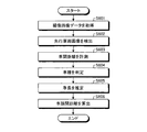
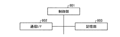
次に、図7〜9を用いて、本実施形態にかかるプローブ情報処理サーバSにおける交通情報の推定処理および運転制御情報の生成処理について説明する。図7は、本実施形態にかかるプローブ情報処理サーバにおける交通情報の推定処理および運転制御情報の生成処理の一例を説明するための図である。図8は、本実施形態にかかるプローブ情報処理サーバのハードウェア構成の一例を示す図である。図9は、本実施形態にかかるプローブ情報処理サーバにおける交通情報の推定処理および運転制御情報の生成処理の流れの一例を示すフローチャートである。   Next, traffic information estimation processing and driving control information generation processing in the probe information processing server S according to the present embodiment will be described with reference to FIGS. FIG. 7 is a diagram for explaining an example of traffic information estimation processing and driving control information generation processing in the probe information processing server according to the present embodiment. FIG. 8 is a diagram illustrating an example of a hardware configuration of the probe information processing server according to the present embodiment. FIG. 9 is a flowchart illustrating an example of the flow of traffic information estimation processing and driving control information generation processing in the probe information processing server according to the present embodiment.

図8に示すように、プローブ情報処理サーバSは、制御部801と、通信I/F802と、記憶部803と、を有する。制御部801は、プローブ情報処理サーバS全体を制御する。本実施形態では、制御部801は、CPU(Central Processing Unit)等を含むマイクロコンピュータで構成される。通信I/F802は、インターネット等のネットワークNTを介して、プローブ車両1および中央処理装置CSと通信可能である。記憶部803は、制御部801によるプローブ情報処理サーバSの制御に用いる各種プログラム等を不揮発的に記憶するROM、当該ROMに記憶された各種プログラムを実行する際の作業領域として用いられるRAM、プローブ情報、運転制御情報、交通情報等の各種情報を不揮発的に記憶するフラッシュROM等を有する。   As illustrated in FIG. 8, the probe information processing server S includes a control unit 801, a communication I / F 802, and a storage unit 803. The control unit 801 controls the entire probe information processing server S. In the present embodiment, the control unit 801 is configured by a microcomputer including a CPU (Central Processing Unit) and the like. Communication I / F 802 can communicate with probe vehicle 1 and central processing unit CS via network NT such as the Internet. A storage unit 803 is a ROM that stores various programs used for controlling the probe information processing server S by the control unit 801 in a nonvolatile manner, a RAM that is used as a work area when executing the various programs stored in the ROM, and a probe It has a flash ROM or the like that stores various information such as information, driving control information, and traffic information in a nonvolatile manner.

図7に示すように、制御部801(受信部の一例)は、まず、ネットワークNTおよび基地局Bを介して、プローブ車両1から、プローブ情報を受信する(ステップS901)。次いで、制御部801は、地図上における道路を分割した区間のうち、受信したプローブ情報が含む位置情報が示す走行位置が属する区間に対して、当該受信したプローブ情報を割り当てるマッピング処理を実行する(ステップS902)。また、制御部801(推定部の一例)は、区間(例えば、500m間隔)毎に、当該区間に割り当てられたプローブ情報に基づいて、交通情報を推定する(ステップS903)。すなわち、制御部801は、プローブ車両1から受信したプローブ情報に基づいて、地図上における道路の各区間の交通情報を推定する。本実施形態では、制御部801は、道路上の車両の粗密情報、空きスペース、移動方向、危険個所、および渋滞情報のうち少なくとも1つの交通情報として推定する。ステップS903に示す処理の詳細については、後述する。さらに、制御部801は、受信したプローブ情報が含む個別車両運転特性を特定する(ステップS904)。   As illustrated in FIG. 7, the control unit 801 (an example of a receiving unit) first receives probe information from the probe vehicle 1 via the network NT and the base station B (step S901). Next, the control unit 801 executes a mapping process for allocating the received probe information to a section to which the traveling position indicated by the position information included in the received probe information belongs, among the sections obtained by dividing the road on the map ( Step S902). In addition, the control unit 801 (an example of an estimation unit) estimates traffic information for each section (for example, at an interval of 500 m) based on the probe information assigned to the section (step S903). That is, the control unit 801 estimates the traffic information of each section of the road on the map based on the probe information received from the probe vehicle 1. In the present embodiment, the control unit 801 estimates as at least one piece of traffic information among the density information of the vehicle on the road, the empty space, the moving direction, the dangerous location, and the traffic jam information. Details of the processing shown in step S903 will be described later. Furthermore, the control unit 801 specifies individual vehicle driving characteristics included in the received probe information (step S904).

次いで、制御部801は、運転制御対象のプローブ車両1が走行する走行位置(すなわち、当該プローブ車両1から受信した位置情報が示す走行位置)が属する区間(以下、走行区間と言う)の交通情報に対応する推奨走行方法を特定する(ステップS905)。本実施形態では、記憶部803は、交通情報と当該交通情報に対応する推奨走行方法とを対応付けて記憶している。そして、制御部801は、記憶部803において、推定した交通情報と対応付けて記憶された推奨走行方法を、運転制御対象のプローブ車両1の推奨走行方法として特定する。推奨走行方法は、交通情報の推定に適したプローブ情報を取得可能とする走行方法である。本実施形態では、推奨走行方法は、走行区間の交通情報に応じたプローブ車両1の走行速度、車間距離または車頭間距離、車線等を含む。   Next, the control unit 801 has traffic information of a section (hereinafter referred to as a travel section) to which the travel position (that is, the travel position indicated by the position information received from the probe vehicle 1) traveled by the probe vehicle 1 subject to operation control belongs. A recommended traveling method corresponding to is identified (step S905). In the present embodiment, the storage unit 803 stores traffic information and a recommended traveling method corresponding to the traffic information in association with each other. Then, the control unit 801 specifies the recommended travel method stored in the storage unit 803 in association with the estimated traffic information as the recommended travel method of the probe vehicle 1 to be controlled. The recommended travel method is a travel method that enables acquisition of probe information suitable for traffic information estimation. In the present embodiment, the recommended travel method includes the travel speed of the probe vehicle 1 according to the traffic information of the travel section, the inter-vehicle distance or the inter-vehicle distance, the lane, and the like.

また、制御部801は、運転制御対象のプローブ車両1が走行する走行位置の道路の交通情報に対応する推奨運転特性(本実施形態では、安全運転度、エコ運転度、および移動効率)を特定する。   In addition, the control unit 801 specifies recommended driving characteristics (in this embodiment, safe driving degree, eco driving degree, and movement efficiency) corresponding to traffic information of a road at a driving position where the probe vehicle 1 to be driven is driven. To do.

そして、制御部801は、運転制御対象のプローブ車両1から受信したプローブ情報に基づく当該プローブ車両1の走行方法と、特定した推奨走行方法との差分を取得する走行改善項目分析処理を実行する(ステップS906)。図7に示すように、さらに、制御部801(生成部の一例)は、走行改善項目分析処理により取得した差分に基づいて、当該差分を減少させることを指示する運転制御情報を生成する(ステップS907)。本実施形態では、制御部801は、予め設定された時間毎に、運転制御情報を生成しなおすものとする。   And the control part 801 performs the driving | running | working improvement item analysis process which acquires the difference of the driving | running | working method of the said probe vehicle 1 based on the probe information received from the probe vehicle 1 of driving control object, and the specified recommended driving | running | working method ( Step S906). As illustrated in FIG. 7, the control unit 801 (an example of a generation unit) further generates driving control information instructing to decrease the difference based on the difference acquired by the travel improvement item analysis process (step). S907). In the present embodiment, the control unit 801 regenerates the operation control information for each preset time.

ここで、走行区間の交通情報が渋滞を示している場合に生成する運転制御情報について説明する。制御部801は、運転制御対象のプローブ車両1の走行速度が、推奨走行方法が含む走行速度より速い場合、減速を指示する走行指示を含む運転制御情報を生成する。また、制御部801は、運転制御対象のプローブ車両1の車間距離が、推奨走行方法が含む車間距離である場合、現在の車間距離の維持を指示する車間指示を含む運転制御情報を生成する。一方、制御部801は、運転制御対象のプローブ車両1の車間距離が、推奨走行方法が含む車間距離より短い場合、車間距離の延長を指示する車間指示を含む運転制御情報を生成する。また、制御部801は、運転制御対象のプローブ車両1の車線が、推奨走行方法が含む車線(例えば、左車線)である場合、現在の車線の維持を指示する車線指示を含む運転制御情報を生成する。   Here, the driving control information generated when the traffic information of the travel section indicates a traffic jam will be described. The control unit 801 generates driving control information including a driving instruction for instructing deceleration when the driving speed of the probe vehicle 1 to be driving controlled is faster than the driving speed included in the recommended driving method. In addition, when the inter-vehicle distance of the probe vehicle 1 that is the target of operation control is the inter-vehicle distance included in the recommended travel method, the control unit 801 generates operation control information including an inter-vehicle instruction that instructs maintenance of the current inter-vehicle distance. On the other hand, when the inter-vehicle distance of the probe vehicle 1 subject to operation control is shorter than the inter-vehicle distance included in the recommended travel method, the control unit 801 generates operation control information including an inter-vehicle instruction that instructs extension of the inter-vehicle distance. In addition, when the lane of the probe vehicle 1 that is the target of operation control is the lane included in the recommended travel method (for example, the left lane), the control unit 801 displays the operation control information including the lane instruction that instructs the maintenance of the current lane. Generate.

次に、走行区間の交通情報が自由流を示している場合に生成する運転制御情報について説明する。制御部801は、運転制御対象のプローブ車両1の走行速度が、推奨走行方法が含む走行速度より遅い場合、加速を指示する走行指示を含む運転制御情報を生成する。また、制御部801は、運転制御対象のプローブ車両1の車間距離が、推奨走行方法が含む車間距離より長い場合、車間距離の短縮を指示する車間指示を含む運転制御情報を生成する。一方、制御部801は、運転制御対象のプローブ車両1の車間距離が、推奨走行方法が含む車間距離より短い場合、車間距離の延長を指示する車間指示を含む運転制御情報を生成する。また、制御部801は、運転制御対象のプローブ車両1の車線が、推奨走行方法が含む車線(例えば、右車線)である場合、現在の車線の維持を指示する車線指示を含む運転制御情報を生成する。一方、制御部801は、運転制御対象のプローブ車両1の車線が、推奨走行方法が含む車線(例えば、右車線)と異なる場合、右車線への変更を指示する車線指示を含む運転制御情報を生成する。   Next, the driving control information generated when the traffic information of the travel section indicates a free flow will be described. The control unit 801 generates driving control information including a driving instruction for instructing acceleration when the driving speed of the probe vehicle 1 to be driving controlled is slower than the driving speed included in the recommended driving method. In addition, when the inter-vehicle distance of the probe vehicle 1 subject to operation control is longer than the inter-vehicle distance included in the recommended travel method, the control unit 801 generates operation control information including an inter-vehicle instruction that instructs to shorten the inter-vehicle distance. On the other hand, when the inter-vehicle distance of the probe vehicle 1 subject to operation control is shorter than the inter-vehicle distance included in the recommended travel method, the control unit 801 generates operation control information including an inter-vehicle instruction that instructs extension of the inter-vehicle distance. In addition, when the lane of the probe vehicle 1 to be controlled for driving is a lane included in the recommended travel method (for example, the right lane), the control unit 801 displays driving control information including a lane instruction that instructs to maintain the current lane. Generate. On the other hand, when the lane of the probe vehicle 1 subject to operation control is different from the lane (for example, the right lane) included in the recommended driving method, the control unit 801 displays the operation control information including the lane instruction instructing the change to the right lane. Generate.

本実施形態では、制御部801は、速度指示、車間指示、および車線指示を含む運転制御情報を生成しているが、走行改善項目分析処理により取得された差分を示す情報を運転制御情報として生成しても良い。例えば、制御部801は、運転制御対象のプローブ車両1の車頭間距離と、推奨走行方法が含む車頭間距離との差分を示す運転制御情報を生成する。   In the present embodiment, the control unit 801 generates driving control information including a speed instruction, an inter-vehicle instruction, and a lane instruction, but generates information indicating the difference acquired by the travel improvement item analysis process as the driving control information. You may do it. For example, the control unit 801 generates driving control information indicating the difference between the head-to-head distance of the probe vehicle 1 to be driven and the head-to-head distance included in the recommended travel method.

図9に戻り、制御部801は、運転制御対象のプローブ車両1から受信したプローブ情報が個別車両運転特性を含む場合、当該個別車両運転特性と、特定した推奨運転特性とを比較し、その比較結果に基づいて、個別車両運転特性を推奨運転特性に近づけることを指示する運転制御情報を生成する。その後、制御部801(送信部の一例)は、図7に示すように、通信I/F802を介して、当該生成した運転制御情報を、運転制御対象のプローブ車両1に対して送信する(ステップS908)。これにより、プローブ車両1の走行方法を、交通情報の推定に適したプローブ情報を取得可能な走行方法に近づけることができるので、交通情報の推定精度を向上させることができる。本実施形態では、制御部801は、予め設定された時間毎に運転制御情報が生成される度に、当該運転制御情報を、運転制御対象のプローブ車両1に対して送信するものとする。また、本実施形態では、制御部801は、図7に示すように、地図上の道路の区間毎の交通情報を、ネットワークNTを介して、中央処理装置CSに送信する。   Returning to FIG. 9, when the probe information received from the probe vehicle 1 that is the operation control target includes the individual vehicle driving characteristics, the control unit 801 compares the individual vehicle driving characteristics with the specified recommended driving characteristics, and compares them. Based on the result, driving control information for instructing to bring the individual vehicle driving characteristics closer to the recommended driving characteristics is generated. Thereafter, the control unit 801 (an example of a transmission unit) transmits the generated driving control information to the probe vehicle 1 that is the target of driving control via the communication I / F 802 as shown in FIG. S908). Thereby, since the traveling method of the probe vehicle 1 can be brought close to a traveling method capable of acquiring probe information suitable for traffic information estimation, it is possible to improve the traffic information estimation accuracy. In this embodiment, the control part 801 shall transmit the said driving control information with respect to the probe vehicle 1 of driving control whenever the driving control information is produced | generated for every preset time. In the present embodiment, as shown in FIG. 7, the control unit 801 transmits traffic information for each road section on the map to the central processing unit CS via the network NT.

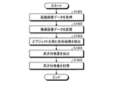
次に、図10を用いて、プローブ情報処理サーバSによる交通情報の推定処理について説明する。図10は、本実施形態にかかるプローブ情報処理サーバによる交通情報の推定処理の流れの一例を示すフローチャートである。   Next, traffic information estimation processing by the probe information processing server S will be described with reference to FIG. FIG. 10 is a flowchart illustrating an example of a flow of traffic information estimation processing by the probe information processing server according to the present embodiment.

制御部801は、プローブ情報のマッピング処理を行った地図上における道路の各区間を走行する車両の粗密情報を推定する(ステップS1001)。具体的には、制御部801は、地図上の道路を複数の区間に分割する。次いで、制御部801は、各区間における車両の占有率に基づいて、地図上の道路における車両の分布(以下、車両分布と言う)を算出する。そして、制御部801は、算出した車両分布を粗密情報とする。   The control unit 801 estimates coarse / dense information of a vehicle traveling on each section of the road on the map on which the probe information mapping process has been performed (step S1001). Specifically, the control unit 801 divides a road on the map into a plurality of sections. Next, the control unit 801 calculates the distribution of vehicles on the road on the map (hereinafter referred to as vehicle distribution) based on the vehicle occupancy rate in each section. Then, the control unit 801 uses the calculated vehicle distribution as density information.

次に、制御部801は、推定した粗密情報(すなわち、車両分布)に基づいて、地図上の道路の空きスペース(例えば、車両が存在しない道路または車両が少ない道路)を推定する(ステップS1002)。また、制御部801は、同一のプローブ車両1から受信するプローブ情報の変化に基づいて、地図上の道路における車両の移動方向を推定する(ステップS1003)。また、制御部801は、車両分布、空きスペース、および移動方向に基づいて、車両の接触や衝突等が発生し易い危険個所を推定する(ステップS1004)。   Next, the control unit 801 estimates an empty space of a road on the map (for example, a road where there are no vehicles or a road with few vehicles) based on the estimated density information (ie, vehicle distribution) (step S1002). . Further, the control unit 801 estimates the moving direction of the vehicle on the road on the map based on the change in the probe information received from the same probe vehicle 1 (step S1003). In addition, the control unit 801 estimates a dangerous place where a vehicle contact or a collision is likely to occur based on the vehicle distribution, the empty space, and the moving direction (step S1004).

さらに、制御部801は、車両分布、空きスペース、および移動方向に基づいて、閑散、混雑、渋滞等の交通のパターンを渋滞情報として推定する(ステップS1005)。さらに、制御部801は、地図上の各道路に割り当てられているプローブ情報が含む車頭間距離または車間距離を用いて、交通工学の理論に従って、各道路の車両の密度または流量である交通量を交通情報として推定する(ステップS1006)。本実施形態では、制御部801は、粗密情報、空きスペース、移動方向、危険個所、および渋滞情報を交通情報として推定しているが、粗密情報、空きスペース、移動方向、危険個所、および渋滞情報のうち少なくとも1つを交通情報として推定するものであれば良い。   Furthermore, the control unit 801 estimates traffic patterns such as light, congestion, and traffic jam as traffic jam information based on the vehicle distribution, the empty space, and the moving direction (step S1005). Furthermore, the control unit 801 uses the distance between the heads or the distance between the vehicles included in the probe information assigned to each road on the map to determine the traffic volume that is the density or flow rate of the vehicle on each road according to the theory of traffic engineering. It is estimated as traffic information (step S1006). In the present embodiment, the control unit 801 estimates the density information, the empty space, the moving direction, the dangerous location, and the traffic jam information as traffic information. However, the density information, the empty space, the moving direction, the dangerous location, and the traffic jam information are estimated. What is necessary is just to estimate at least one of them as traffic information.

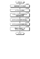
次に、図11を用いて、プローブ車両1における個別車両運転特性の特定処理について説明する。図11は、本実施形態にかかるプローブ車両による個別車両運転特性の特定処理の流れの一例を示すフローチャートである。   Next, the individual vehicle driving characteristic specifying process in the probe vehicle 1 will be described with reference to FIG. FIG. 11 is a flowchart showing an example of the flow of individual vehicle driving characteristic specifying processing by the probe vehicle according to the present embodiment.

制御部401(安全度判定部の一例)は、プローブ車両1と先行車両2との車間距離または車頭間距離、プローブ車両1の走行位置、およびプローブ車両1の走行速度の少なくとも1つの時間変化に基づいて、プローブ車両1の安全運転度を判定する(ステップS1101)。また、制御部401(エコ運転度判定部の一例)は、プローブ車両1の加減速およびプローブ車両1の走行速度の平均の少なくとも1つに基づいて、プローブ車両1のエコ運転度を判定する(ステップS1102)。さらに、制御部401(移動効率算出部の一例)は、プローブ車両1の走行位置の時間変化に基づいて、移動効率を算出する(ステップS1103)。   The control unit 401 (an example of a safety degree determination unit) changes at least one time change in the inter-vehicle distance or the head-to-vehicle distance between the probe vehicle 1 and the preceding vehicle 2, the travel position of the probe vehicle 1, and the travel speed of the probe vehicle 1. Based on this, the degree of safe driving of the probe vehicle 1 is determined (step S1101). Further, the control unit 401 (an example of the eco-driving degree determination unit) determines the eco-driving degree of the probe vehicle 1 based on at least one of the acceleration / deceleration of the probe vehicle 1 and the average traveling speed of the probe vehicle 1 ( Step S1102). Furthermore, the control unit 401 (an example of the movement efficiency calculation unit) calculates the movement efficiency based on the time change of the travel position of the probe vehicle 1 (step S1103).

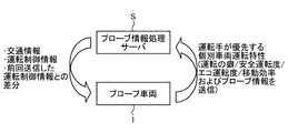
次に、図12を用いて、プローブ車両1とプローブ情報処理サーバS間における各種情報の送受信処理の一例について説明する。図12は、本実施形態にかかるプローブ情報処理システムにおけるプローブ車両とプローブ情報処理サーバ間における各種情報の送受信処理の一例を説明するための図である。   Next, an example of a transmission / reception process of various information between the probe vehicle 1 and the probe information processing server S will be described with reference to FIG. FIG. 12 is a diagram for explaining an example of various information transmission / reception processes between the probe vehicle and the probe information processing server in the probe information processing system according to the present embodiment.

プローブ車両1は、予め設定された時間毎に、プローブ情報をプローブ情報処理サーバSに送信する。また、プローブ車両1は、運転の癖、安全運転度、エコ運転度、および移動効率のうち、当該プローブ車両1の運転手が優先する個別車両運転特性をプローブ情報処理サーバSに送信する。プローブ情報処理サーバSは、運転制御対象のプローブ車両1から受信したプローブ情報に基づく当該プローブ車両1の走行方法と、当該プローブ車両1が走行する区間の交通情報に基づく推奨走行方法との差分に基づいて運転制御情報を生成する。   The probe vehicle 1 transmits probe information to the probe information processing server S every preset time. Further, the probe vehicle 1 transmits to the probe information processing server S the individual vehicle driving characteristics that are given priority by the driver of the probe vehicle 1 among the driving habits, the safe driving degree, the eco driving degree, and the movement efficiency. The probe information processing server S determines the difference between the traveling method of the probe vehicle 1 based on the probe information received from the probe vehicle 1 to be controlled and the recommended traveling method based on the traffic information of the section in which the probe vehicle 1 travels. Based on this, operation control information is generated.

さらに、プローブ情報処理サーバSは、各区間に割り当てられたプローブ情報に基づいて、プローブ車両1の走行位置が属する区間の交通情報に対応する推奨運転特性を生成する。次いで、プローブ情報処理サーバSは、生成した推奨運転特性と、運転制御対象のプローブ車両1の個別車両運転特性とを比較し、その比較結果を、運転制御情報に含める。その後、プローブ情報処理サーバSは、生成した運転制御情報を、運転制御対象のプローブ車両1に送信する。また、プローブ情報処理サーバSは、運転制御対象のプローブ車両1の走行位置が属する区間の交通情報を、当該プローブ車両1に送信しても良い。また、プローブ情報処理サーバSは、運転制御対象のプローブ車両1に前回送信した運転制御情報と、当該プローブ車両1に今回送信する運転制御情報の差分を、当該プローブ車両1に送信しても良い。   Furthermore, the probe information processing server S generates recommended driving characteristics corresponding to the traffic information of the section to which the traveling position of the probe vehicle 1 belongs based on the probe information assigned to each section. Next, the probe information processing server S compares the generated recommended driving characteristic with the individual vehicle driving characteristic of the probe vehicle 1 to be controlled, and includes the comparison result in the driving control information. Thereafter, the probe information processing server S transmits the generated driving control information to the probe vehicle 1 that is a driving control target. Further, the probe information processing server S may transmit the traffic information of the section to which the traveling position of the probe vehicle 1 that is the operation control target belongs to the probe vehicle 1. In addition, the probe information processing server S may transmit to the probe vehicle 1 the difference between the operation control information that was previously transmitted to the probe vehicle 1 that is the object of operation control and the operation control information that is currently transmitted to the probe vehicle 1. .

ただし、プローブ車両1は、周囲を走行する車両との関係で局所的な安全を考慮して走行を行うため、プローブ情報処理サーバSから受信した運転制御情報に従った走行を行うと、他の車両と接触または衝突する可能性がある。そのため、プローブ情報処理サーバSは、個別車両運転特性のうち優先する所定の個別車両運転特性と、推奨運転特性との比較結果のみを含む運転制御情報を、運転制御対象のプローブ車両1に送信しても良い。これにより、プローブ車両1が、運転制御情報に従って運転された結果、他の車両と接触または衝突する可能性を低減することができる。   However, since the probe vehicle 1 travels in consideration of local safety in relation to a vehicle traveling around, when traveling according to the operation control information received from the probe information processing server S, Possible contact or collision with the vehicle. Therefore, the probe information processing server S transmits driving control information including only a comparison result between a predetermined individual vehicle driving characteristic having priority among the individual vehicle driving characteristics and a recommended driving characteristic to the probe vehicle 1 to be driven. May be. Thereby, as a result of driving the probe vehicle 1 according to the driving control information, it is possible to reduce the possibility of contact or collision with another vehicle.

次に、図13〜20を用いて、プローブ車両1において個別車両運転特性を取得する処理について説明する。図13は、本実施形態にかかるプローブ車両の機能構成の一例を示すブロック図である。   Next, a process for acquiring individual vehicle driving characteristics in the probe vehicle 1 will be described with reference to FIGS. FIG. 13 is a block diagram illustrating an example of a functional configuration of the probe vehicle according to the present embodiment.

図13に示すように、プローブ車両1は、制御部401が記憶部403に記憶されたプログラムを実行することによって、ドライバモニタリング機能部1301と、外部センシング機能部1302と、学習機能部1303と、運転モニタリング機能部1304と、運転ログ収集・分析機能部1305と、を実現する。   As illustrated in FIG. 13, the probe vehicle 1 causes the driver 401 monitoring function unit 1301, the external sensing function unit 1302, the learning function unit 1303, when the control unit 401 executes the program stored in the storage unit 403. An operation monitoring function unit 1304 and an operation log collection / analysis function unit 1305 are realized.

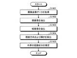
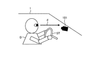
図14Aは、本実施形態にかかるプローブ車両の運転手による外界の認識状況を推定する処理の流れの一例を示すフローチャートである。図14Bは、本実施形態にかかるプローブ車両の運転手の視線方向を検出する処理の一例を説明するための図である。ドライバモニタリング機能部1301は、プローブ車両1の運転手を監視する。具体的には、図14Aに示すように、ドライバモニタリング機能部1301は、有線ネットワークまたは無線ネットワークを介して、カメラ101によりプローブ車両1の車内を撮像して得られた撮像画像データを取得する(ステップS1401)。次いで、ドライバモニタリング機能部1301は、取得した撮像画像データから、プローブ車両1の運転手の顔画像を抽出する(ステップS1402)。本実施形態では、ドライバモニタリング機能部1301は、図14Bに示すように、カメラ101の撮像により得られた撮像画像データに基づいて、プローブ車両1の座席に着座してステアリングホイールSTを握る運転手Dの視線方向dを検出する。さらに、ドライバモニタリング機能部1301は、抽出した顔画像から、プローブ車両1の運転手の瞳画像を抽出する(ステップS1403)。   FIG. 14A is a flowchart illustrating an example of a flow of processing for estimating the recognition status of the outside world by the driver of the probe vehicle according to the present embodiment. FIG. 14B is a diagram for explaining an example of a process of detecting the line-of-sight direction of the driver of the probe vehicle according to the present embodiment. The driver monitoring function unit 1301 monitors the driver of the probe vehicle 1. Specifically, as illustrated in FIG. 14A, the driver monitoring function unit 1301 acquires captured image data obtained by imaging the interior of the probe vehicle 1 with the camera 101 via a wired network or a wireless network ( Step S1401). Next, the driver monitoring function unit 1301 extracts the face image of the driver of the probe vehicle 1 from the acquired captured image data (step S1402). In the present embodiment, as shown in FIG. 14B, the driver monitoring function unit 1301 is a driver who sits on the seat of the probe vehicle 1 and holds the steering wheel ST based on captured image data obtained by imaging with the camera 101. A line-of-sight direction d of D is detected. Further, the driver monitoring function unit 1301 extracts a pupil image of the driver of the probe vehicle 1 from the extracted face image (step S1403).

そして、ドライバモニタリング機能部1301は、抽出した瞳画像から、プローブ車両1の運転手の視線方向および瞬きを検出する(ステップS1404)。その後、ドライバモニタリング機能部1301は、プローブ車両1の運転手の視線方向および瞬きの検出結果に基づいて、当該運転手が注視している注視領域や当該運転手が注視している注視時間を推定する。さらに、ドライバモニタリング機能部1301は、推定した注視領域および注視時間に基づいて、プローブ車両1の運転手による外界の認識状況を推定する(ステップS1405)。   Then, the driver monitoring function unit 1301 detects the line-of-sight direction and blink of the driver of the probe vehicle 1 from the extracted pupil image (step S1404). Thereafter, the driver monitoring function unit 1301 estimates the gaze area that the driver is gazing at and the gaze time that the driver is gazing based on the detection result of the gaze direction and blink of the driver of the probe vehicle 1. To do. Furthermore, the driver monitoring function unit 1301 estimates the external environment recognition status by the driver of the probe vehicle 1 based on the estimated gaze area and gaze time (step S1405).

図15は、本実施形態にかかるプローブ車両による外界のオブジェクトの検出処理の流れの一例を示すフローチャートである。外部センシング機能部1302は、プローブ車両1の外界のオブジェクトを検出する。具体的には、図15に示すように、外部センシング機能部1302は、有線ネットワークまたは無線ネットワークを介して、カメラ102〜104の撮像により得られた撮像画像データを取得する(ステップS1501)。次いで、外部センシング機能部1302は、取得した撮像画像データから、プローブ車両1の外界に存在するオブジェクト(例えば、障害物、歩行者)を検出する(ステップS1502)。また、外部センシング機能部1302は、有線ネットワークまたは無線ネットワークを介して、レーダ105から出力される距離情報を取得する(ステップS1503)。   FIG. 15 is a flowchart illustrating an example of a flow of processing for detecting an object in the outside world by the probe vehicle according to the present embodiment. The external sensing function unit 1302 detects an object outside the probe vehicle 1. Specifically, as illustrated in FIG. 15, the external sensing function unit 1302 acquires captured image data obtained by imaging with the cameras 102 to 104 via a wired network or a wireless network (step S1501). Next, the external sensing function unit 1302 detects an object (for example, an obstacle or a pedestrian) existing in the external environment of the probe vehicle 1 from the acquired captured image data (step S1502). Also, the external sensing function unit 1302 acquires distance information output from the radar 105 via a wired network or a wireless network (step S1503).

外部センシング機能部1302は、レーダ105から出力される距離情報およびカメラ102〜104から取得した撮像画像データに基づいて、プローブ車両1を基準とする、オブジェクトの移動方向およびオブジェクトの相対速度を推定する(ステップS1504、ステップS1505)。その後、外部センシング機能部1302は、オブジェクトの移動方向およびオブジェクトの相対速度の推定結果に基づいて、プローブ車両1の走行において運転手が認識すべきオブジェクトを検出する(ステップS1506)。   The external sensing function unit 1302 estimates the moving direction of the object and the relative speed of the object with reference to the probe vehicle 1 based on the distance information output from the radar 105 and the captured image data acquired from the cameras 102 to 104. (Step S1504, Step S1505). Thereafter, the external sensing function unit 1302 detects an object that the driver should recognize in the traveling of the probe vehicle 1 based on the estimation result of the moving direction of the object and the relative speed of the object (step S1506).

図16は、本実施形態にかかるプローブ車両による撮像画像データを記憶する処理の流れの一例を示すフローチャートである。図17は、本実施形態にかかるプローブ車両による高次特徴量を記憶する処理の一例を説明するための図である。学習機能部1303は、カメラ101〜104の撮像により得られた撮像画像データを収集し、記憶する。具体的には、図16に示すように、学習機能部1303は、カメラ101〜104の撮像により得られた撮像画像データを取得する(ステップS1601)。さらに、学習機能部1303は、取得した撮像画像データを記憶する(ステップS1602)。次いで、学習機能部1303は、図17に示すように、取得した撮像画像データにおいて、外部センシング機能部1302により検出されたオブジェクトを囲む矩形画像SGを検出する(ステップS1603)。そして、学習機能部1303は、抽出した矩形画像SG内の高次特徴量を抽出する(ステップS1604)。その後、学習機能部1303は、抽出した矩形画像SGの高次特徴量を記憶する(ステップS1605)。外部センシング機能部1302は、図15のステップS1502において撮像画像データからオブジェクトを検出する際、撮像画像データにおいて、学習機能部1303が記憶する高次特徴量を有する領域を、オブジェクトとして検出する。   FIG. 16 is a flowchart illustrating an example of a flow of processing for storing captured image data by the probe vehicle according to the present embodiment. FIG. 17 is a diagram for explaining an example of processing for storing higher-order feature values by the probe vehicle according to the present embodiment. The learning function unit 1303 collects and stores captured image data obtained by imaging with the cameras 101 to 104. Specifically, as illustrated in FIG. 16, the learning function unit 1303 acquires captured image data obtained by imaging with the cameras 101 to 104 (step S1601). Furthermore, the learning function unit 1303 stores the acquired captured image data (step S1602). Next, as shown in FIG. 17, the learning function unit 1303 detects a rectangular image SG surrounding the object detected by the external sensing function unit 1302 in the acquired captured image data (step S1603). Then, the learning function unit 1303 extracts higher-order feature amounts in the extracted rectangular image SG (step S1604). Thereafter, the learning function unit 1303 stores the higher-order feature amount of the extracted rectangular image SG (step S1605). When the external sensing function unit 1302 detects an object from the captured image data in step S1502 of FIG. 15, the external sensing function unit 1302 detects, in the captured image data, an area having a higher-order feature amount stored by the learning function unit 1303 as an object.

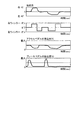
図18は、本実施形態にかかるプローブ車両による運転操作の検出処理の流れの一例を示すフローチャートである。図19は、本実施形態にかかるプローブ車両による運転操作の検出処理の一例を説明するための図である。運転モニタリング機能部1304は、プローブ車両1の運転操作を検出する。具体的には、図18に示すように、運転モニタリング機能部1304は、プローブ車両1の運転手によるステアリングの操舵角、アクセスペダルおよびブレーキペダルの踏込量、左右のウィンカーのオンまたはオフなど、プローブ車両1に対する運転手の運転操作を取得する(ステップS1801)。そして、運転モニタリング機能部1304は、図19に示すように、取得した各運転操作を、時系列に並べて記憶する(ステップS1802)。   FIG. 18 is a flowchart illustrating an example of a flow of detection processing of a driving operation by the probe vehicle according to the present embodiment. FIG. 19 is a diagram for explaining an example of the driving operation detection process by the probe vehicle according to the present embodiment. The driving monitoring function unit 1304 detects the driving operation of the probe vehicle 1. Specifically, as shown in FIG. 18, the driving monitoring function unit 1304 includes a probe steering angle by the driver of the probe vehicle 1, the amount of depression of the access pedal and the brake pedal, the on / off of the left and right winkers, and the like. The driver's driving operation for the vehicle 1 is acquired (step S1801). Then, as shown in FIG. 19, the driving monitoring function unit 1304 stores the acquired driving operations in time series (step S1802).

次に、運転モニタリング機能部1304は、記憶した各運転操作に応じた、プローブ車両1の挙動および当該プローブ車両1の走行軌跡を推定する(ステップS1803)。そして、運転モニタリング機能部1304は、推定したプローブ車両1の挙動およびプローブ車両1の走行軌跡を出力する(ステップS1804)。   Next, the driving monitoring function unit 1304 estimates the behavior of the probe vehicle 1 and the travel locus of the probe vehicle 1 according to each stored driving operation (step S1803). Then, the driving monitoring function unit 1304 outputs the estimated behavior of the probe vehicle 1 and the travel locus of the probe vehicle 1 (step S1804).

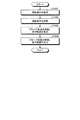
図20は、本実施形態にかかるプローブ車両による個別車両運転特性の検出処理の流れの一例を示すフローチャートである。運転ログ収集・分析機能部1305は、プローブ車両1の個別車両運転特性を検出する。具体的には、図20に示すように、運転ログ収集・分析機能部1305は、ドライバモニタリング機能部1301によるプローブ車両1の運転手の監視結果、外部センシング機能部1302によるプローブ車両1の外界のオブジェクトの検出結果、および運転モニタリング機能部1304によるプローブ車両1の運転手の運転操作の検出結果に基づいて、プローブ車両1の運転手による外界のオブジェクトの視認の漏れや遅れを検出する(ステップS2001)。次に、運転ログ収集・分析機能部1305は、プローブ車両1の運転手による外界のオブジェクトの視認の漏れや遅れの検出結果に基づいて、安全運転度を個別車両運転特性として取得する(ステップS2002)。また、運転ログ収集・分析機能部1305は、運転モニタリング機能部1304により推定されたプローブ車両1の挙動および走行軌跡等に基づいて、エコ運転度および移動効率を取得する。そして、運転ログ収集・分析機能部1305は、取得した個別車両運転特性を含むプローブ情報を、プローブ情報処理サーバSに送信する(ステップS2003)。   FIG. 20 is a flowchart showing an example of the flow of the individual vehicle driving characteristic detection process by the probe vehicle according to the present embodiment. The driving log collection / analysis function unit 1305 detects the individual vehicle driving characteristics of the probe vehicle 1. Specifically, as shown in FIG. 20, the driving log collection / analysis function unit 1305 monitors the driver's monitoring result of the probe vehicle 1 by the driver monitoring function unit 1301 and the external environment of the probe vehicle 1 by the external sensing function unit 1302. Based on the detection result of the object and the detection result of the driving operation of the driver of the probe vehicle 1 by the driving monitoring function unit 1304, a leakage or delay in visual recognition of an object in the outside world by the driver of the probe vehicle 1 is detected (step S2001). ). Next, the driving log collection / analysis function unit 1305 acquires the safe driving degree as the individual vehicle driving characteristic based on the detection result of the leakage or delay of the visual recognition of the external object by the driver of the probe vehicle 1 (step S2002). ). In addition, the driving log collection / analysis function unit 1305 acquires the eco-driving degree and the movement efficiency based on the behavior of the probe vehicle 1 and the traveling locus estimated by the driving monitoring function unit 1304. Then, the driving log collection / analysis function unit 1305 transmits probe information including the acquired individual vehicle driving characteristics to the probe information processing server S (step S2003).

このように、本実施形態にかかるプローブ情報処理システムによれば、交通情報の推定精度を向上させることができる。   Thus, according to the probe information processing system concerning this embodiment, the estimation accuracy of traffic information can be improved.

なお、本実施形態の制御部401,801で実行されるプログラムは、ROM等に予め組み込まれて提供される。本実施形態の制御部401,801で実行されるプログラムは、インストール可能な形式又は実行可能な形式のファイルでCD−ROM、フレキシブルディスク(FD)、CD−R、DVD(Digital Versatile Disk)等のコンピュータで読み取り可能な記録媒体に記録して提供するように構成してもよい。   Note that the programs executed by the control units 401 and 801 of the present embodiment are provided by being incorporated in advance in a ROM or the like. A program executed by the control units 401 and 801 of the present embodiment is an installable or executable file, such as a CD-ROM, a flexible disk (FD), a CD-R, or a DVD (Digital Versatile Disk). You may comprise so that it may record and provide on a computer-readable recording medium.

さらに、本実施形態の制御部401,801で実行されるプログラムを、インターネット等のネットワークに接続されたコンピュータ上に格納し、ネットワーク経由でダウンロードさせることにより提供するように構成しても良い。また、本実施形態の制御部401,801で実行されるプログラムをインターネット等のネットワーク経由で提供または配布するように構成しても良い。   Furthermore, the program executed by the control units 401 and 801 of the present embodiment may be stored on a computer connected to a network such as the Internet and provided by being downloaded via the network. Further, the program executed by the control units 401 and 801 of the present embodiment may be configured to be provided or distributed via a network such as the Internet.

本発明の実施形態を説明したが、この実施形態は、例として提示したものであり、発明の範囲を限定することは意図していない。この新規な実施形態は、その他の様々な形態で実施されることが可能であり、発明の要旨を逸脱しない範囲で、種々の省略、置き換え、変更を行うことができる。この実施形態は、発明の範囲や要旨に含まれるとともに、特許請求の範囲に記載された発明とその均等の範囲に含まれる。   Although the embodiment of the present invention has been described, this embodiment is presented as an example and is not intended to limit the scope of the invention. The novel embodiment can be implemented in various other forms, and various omissions, replacements, and changes can be made without departing from the scope of the invention. This embodiment is included in the scope and gist of the invention, and is also included in the invention described in the claims and the equivalent scope thereof.

1 プローブ車両
2 先行車両
100 制御装置
101〜104,202,203 カメラ
105 レーダ
107 ECU
108 表示部
109 スピーカ
110 通信機器
204 GPSアンテナ
205 携帯端末
401,801 制御部
402,802 通信I/F
403,803 記憶部
404 外部記憶装置
S プローブ情報処理サーバ
DESCRIPTION OF SYMBOLS 1 Probe vehicle 2 Leading vehicle 100 Control apparatus 101-104,202,203 Camera 105 Radar 107 ECU
108 Display Unit 109 Speaker 110 Communication Device 204 GPS Antenna 205 Portable Terminal 401, 801 Control Unit 402, 802 Communication I / F
403, 803 Storage unit 404 External storage device S Probe information processing server

Claims (15)

プローブ車両から、当該プローブ車両の走行に関する情報でありかつ前記プローブ車両の走行位置を含むプローブ情報を受信する受信部と、
受信した前記プローブ情報に基づいて、地図上における道路の各区間の交通情報を推定する推定部と、
運転制御対象の前記プローブ車両が走行する前記区間の前記交通情報に対応する推奨走行方法と、前記運転制御対象のプローブ車両から受信した前記プローブ情報に基づく当該プローブ車両の走行方法との差分に基づいて、当該差分を減少させることを指示する運転制御情報を生成する生成部と、
生成した前記運転制御情報を前記運転制御対象のプローブ車両に送信する送信部と、
を備えるプローブ情報処理サーバ。
A receiving unit that receives probe information from the probe vehicle that is information related to the traveling of the probe vehicle and includes the traveling position of the probe vehicle;
An estimation unit that estimates traffic information of each section of the road on the map based on the received probe information;
Based on a difference between a recommended traveling method corresponding to the traffic information of the section in which the probe vehicle to be controlled by driving and a traveling method of the probe vehicle based on the probe information received from the probe vehicle to be controlled by driving A generation unit that generates operation control information instructing to decrease the difference;
A transmission unit that transmits the generated driving control information to the probe vehicle that is the target of driving control;
A probe information processing server comprising:
前記受信部は、前記プローブ車両の運転の癖、安全運転、環境負荷、および移動効率のうち少なくとも1つに関する個別車両運転特性を含む前記プローブ情報を受信し、
前記生成部は、前記運転制御対象のプローブ車両から受信した前記プローブ情報が含む前記個別車両運転特性と、前記運転制御対象のプローブ車両が走行する前記区間の前記交通情報に対応する推奨運転特性とを比較し、その比較結果に基づいて、前記個別車両運転特性を前記推奨運転特性に近づける前記運転制御情報を生成する請求項1に記載のプローブ情報処理サーバ。
The receiving unit receives the probe information including individual vehicle driving characteristics related to at least one of driving habits, safe driving, environmental load, and movement efficiency of the probe vehicle;
The generation unit includes the individual vehicle driving characteristics included in the probe information received from the driving vehicle to be driven and recommended driving characteristics corresponding to the traffic information of the section in which the driving vehicle to be driven is driven. The probe information processing server according to claim 1, wherein the driving control information that makes the individual vehicle driving characteristics closer to the recommended driving characteristics is generated based on the comparison result.
前記個別車両運転特性は、前記プローブ車両の安全運転の度合いを示す安全運転度、前記プローブ車両の走行による環境負荷の度合いを示すエコ運転度、および前記プローブ車両の所定時間当たりの移動距離を示す移動効率の少なくとも1つを含む請求項2に記載のプローブ情報処理サーバ。   The individual vehicle driving characteristics indicate a safe driving degree indicating a degree of safe driving of the probe vehicle, an eco driving degree indicating a degree of environmental load due to the traveling of the probe vehicle, and a moving distance per predetermined time of the probe vehicle. The probe information processing server according to claim 2, comprising at least one of movement efficiencies. 前記交通情報と当該交通情報に対応する前記推奨走行方法とを対応付けて記憶する記憶部をさらに備え、
前記生成部は、前記記憶部において、前記運転制御対象のプローブ車両が走行する道路の前記交通情報と対応付けて記憶された前記推奨走行方法と、前記運転制御対象のプローブ車両の走行方法との差分に基づいて、前記運転制御情報を生成する請求項1から3のいずれか一に記載のプローブ情報処理サーバ。
A storage unit that stores the traffic information and the recommended travel method corresponding to the traffic information in association with each other;
In the storage unit, the generation unit includes the recommended traveling method stored in association with the traffic information of the road on which the probe vehicle that is the operation control target travels, and the traveling method of the probe vehicle that is the operation control target. The probe information processing server according to any one of claims 1 to 3, wherein the operation control information is generated based on a difference.
前記推定部は、地図上の道路の車両の粗密情報、空きスペース、移動方向、危険個所、および渋滞情報のうち少なくとも1つを前記交通情報として推定する請求項1から4のいずれか一に記載のプローブ情報処理サーバ。   5. The estimation unit according to claim 1, wherein the estimation unit estimates at least one of road traffic density information, empty space, moving direction, dangerous location, and traffic jam information on the map as the traffic information. Probe information processing server. 前記プローブ情報は、前記プローブ車両と先行車両との車間距離または車頭間距離を含み、
前記推定部は、前記プローブ情報が含む前記車間距離または前記車頭間距離に基づいて、地図上の道路の車両の密度または流量を前記交通情報として推定する請求項1から5のいずれか一に記載のプローブ情報処理サーバ。
The probe information includes an inter-vehicle distance or a head-to-vehicle distance between the probe vehicle and a preceding vehicle,
The said estimation part estimates the density or flow volume of the vehicle of the road on a map as said traffic information based on the said inter-vehicle distance or the said inter-vehicle head distance which the said probe information contains. Probe information processing server.
プローブ車両の走行に関する情報でありかつ前記プローブ車両の走行位置を含むプローブ情報をプローブ情報処理サーバに送信する送信部と、
前記プローブ情報処理サーバから、前記プローブ車両の走行方法と、前記プローブ情報に基づく地図上における道路の各区間の交通情報に対応する推奨走行方法との差分を減少させることを指示する運転制御情報を受信する受信部と、
受信した前記運転制御情報に従って、前記プローブ車両の走行を制御する制御部と、
を備えたプローブ車両。
A transmitter for transmitting probe information to the probe information processing server, which is information related to travel of the probe vehicle and includes the travel position of the probe vehicle;
Driving control information for instructing to reduce the difference between the traveling method of the probe vehicle and the recommended traveling method corresponding to the traffic information of each section of the road on the map based on the probe information from the probe information processing server. A receiving unit for receiving;
In accordance with the received driving control information, a control unit that controls the traveling of the probe vehicle;
Probe vehicle equipped with.
前記プローブ車両と先行車両との車間距離または車頭間距離、前記プローブ車両の走行位置、および前記プローブ車両の走行速度の少なくとも1つの時間変化に基づいて、前記プローブ車両の安全運転の度合いである安全運転度を判定する安全度判定部をさらに備え、
前記送信部は、前記安全運転度を含む前記プローブ情報を前記プローブ情報処理サーバに送信する請求項7に記載のプローブ車両。
Safety that is the degree of safe driving of the probe vehicle based on at least one temporal change in the inter-vehicle distance or head-to-vehicle distance between the probe vehicle and the preceding vehicle, the travel position of the probe vehicle, and the travel speed of the probe vehicle. It further includes a safety level determination unit that determines the driving degree,
The probe vehicle according to claim 7, wherein the transmission unit transmits the probe information including the safe driving degree to the probe information processing server.
前記プローブ車両の加減速および前記プローブ車両の走行速度の平均の少なくとも1つに基づいて、前記プローブ車両の走行による環境負荷の度合いを示すエコ運転度を判定するエコ運転度判定部をさらに備え、
前記送信部は、前記エコ運転度を含む前記プローブ情報を前記プローブ情報処理サーバに送信する請求項7に記載のプローブ車両。
An eco-driving degree determination unit that determines an eco-driving degree indicating a degree of environmental load caused by traveling of the probe vehicle based on at least one of acceleration / deceleration of the probe vehicle and an average traveling speed of the probe vehicle;
The probe vehicle according to claim 7, wherein the transmission unit transmits the probe information including the eco-driving degree to the probe information processing server.
前記プローブ車両の走行位置の時間変化に基づいて、前記プローブ車両の所定時間当たりの移動距離を示す移動効率を算出する移動効率算出部をさらに備え、
前記送信部は、前記移動効率を含む前記プローブ情報を前記プローブ情報処理サーバに送信する請求項7に記載のプローブ車両。
A movement efficiency calculation unit that calculates a movement efficiency indicating a movement distance per predetermined time of the probe vehicle based on a time change of the travel position of the probe vehicle;
The probe vehicle according to claim 7, wherein the transmission unit transmits the probe information including the movement efficiency to the probe information processing server.
プローブ車両から、当該プローブ車両の走行に関する情報でありかつ前記プローブ車両の走行位置を含むプローブ情報を受信し、
受信した前記プローブ情報に基づいて、地図上における道路の各区間の交通情報を推定し、
運転制御対象の前記プローブ車両が走行する前記区間の前記交通情報に対応する推奨走行方法と、前記運転制御対象のプローブ車両から受信した前記プローブ情報に基づく当該プローブ車両の走行方法との差分に基づいて、当該差分を減少させることを指示する運転制御情報を生成し、
生成した前記運転制御情報を前記運転制御対象のプローブ車両に送信する、
ことを含むプローブ情報処理方法。
From the probe vehicle, the probe information is information related to the travel of the probe vehicle and includes the travel position of the probe vehicle,
Based on the received probe information, the traffic information of each section of the road on the map is estimated,
Based on a difference between a recommended traveling method corresponding to the traffic information of the section in which the probe vehicle to be controlled by driving and a traveling method of the probe vehicle based on the probe information received from the probe vehicle to be controlled by driving To generate operation control information instructing to decrease the difference,
The generated driving control information is transmitted to the driving vehicle subject to driving control.
A probe information processing method.
前記プローブ車両の運転の癖、安全運転、環境負荷、および移動効率のうち少なくとも1つに関する個別車両運転特性を含む前記プローブ情報を受信し、
前記生成部は、前記運転制御対象のプローブ車両から受信した前記プローブ情報が含む前記個別車両運転特性と、前記運転制御対象のプローブ車両が走行する前記区間の前記交通情報に対応する推奨運転特性とを比較し、その比較結果に基づいて、前記個別車両運転特性を前記推奨運転特性に近づける前記運転制御情報を生成する請求項11に記載のプローブ情報処理方法。
Receiving the probe information including individual vehicle driving characteristics related to at least one of driving habits of the probe vehicle, safe driving, environmental load, and movement efficiency;
The generation unit includes the individual vehicle driving characteristics included in the probe information received from the driving vehicle to be driven and recommended driving characteristics corresponding to the traffic information of the section in which the driving vehicle to be driven is driven. The probe information processing method according to claim 11, wherein the driving control information that makes the individual vehicle driving characteristics closer to the recommended driving characteristics is generated based on the comparison result.
前記個別車両運転特性は、前記プローブ車両の安全運転の度合いを示す安全運転度、前記プローブ車両の走行による環境負荷の度合いを示すエコ運転度、および前記プローブ車両の所定時間当たりの移動距離を示す移動効率の少なくとも1つを含む請求項12に記載のプローブ情報処理方法。   The individual vehicle driving characteristics indicate a safe driving degree indicating a degree of safe driving of the probe vehicle, an eco driving degree indicating a degree of environmental load due to the traveling of the probe vehicle, and a moving distance per predetermined time of the probe vehicle. The probe information processing method according to claim 12, comprising at least one of movement efficiencies. 記憶部において、前記運転制御対象のプローブ車両が走行する道路の前記交通情報と対応付けて記憶された前記推奨走行方法と、前記運転制御対象のプローブ車両の走行方法との差分に基づいて、前記運転制御情報を生成する請求項11から13のいずれか一に記載のプローブ情報処理方法。   In the storage unit, based on a difference between the recommended travel method stored in association with the traffic information of the road on which the probe vehicle to be controlled by driving is stored and the traveling method of the probe vehicle to be controlled by driving, The probe information processing method according to claim 11, wherein the operation control information is generated. 前記プローブ情報は、前記プローブ車両と先行車両との車間距離または車頭間距離を含み、
前記プローブ情報が含む前記車間距離または前記車頭間距離に基づいて、地図上の道路の車両の密度または流量を前記交通情報として推定する請求項11から14のいずれか一に記載のプローブ情報処理方法。
The probe information includes an inter-vehicle distance or a head-to-vehicle distance between the probe vehicle and a preceding vehicle,
The probe information processing method according to any one of claims 11 to 14, wherein a density or a flow rate of a road vehicle on a map is estimated as the traffic information based on the inter-vehicle distance or the inter-vehicle head distance included in the probe information. .
JP2016086213A 2016-04-22 2016-04-22 Probe information processing server and probe information processing method Active JP6896374B2 (en)

Priority Applications (1)

Application Number Priority Date Filing Date Title
JP2016086213A JP6896374B2 (en) 2016-04-22 2016-04-22 Probe information processing server and probe information processing method

Applications Claiming Priority (1)

Application Number Priority Date Filing Date Title
JP2016086213A JP6896374B2 (en) 2016-04-22 2016-04-22 Probe information processing server and probe information processing method

Publications (2)

Publication Number Publication Date
JP2017194913A true JP2017194913A (en) 2017-10-26
JP6896374B2 JP6896374B2 (en) 2021-06-30

Family

ID=60156405

Family Applications (1)

Application Number Title Priority Date Filing Date
JP2016086213A Active JP6896374B2 (en) 2016-04-22 2016-04-22 Probe information processing server and probe information processing method

Country Status (1)

Country Link
JP (1) JP6896374B2 (en)

Cited By (6)

* Cited by examiner, † Cited by third party
Publication number Priority date Publication date Assignee Title
WO2019163813A1 (en) * 2018-02-22 2019-08-29 本田技研工業株式会社 Vehicle control system, vehicle control method, and program
JP2019175366A (en) * 2018-03-29 2019-10-10 株式会社トヨタマップマスター Information generating apparatus, information generating method, program, and recording medium
CN112833894A (en) * 2019-11-25 2021-05-25 丰田自动车株式会社 Information providing system, information providing apparatus and non-transitory computer readable medium
CN114495482A (en) * 2020-10-26 2022-05-13 现代自动车株式会社 Apparatus and method for predicting traffic information
JPWO2022145351A1 (en) * 2020-12-28 2022-07-07
JP2024142632A (en) * 2023-03-30 2024-10-11 本田技研工業株式会社 Data communication equipment

Citations (10)

* Cited by examiner, † Cited by third party
Publication number Priority date Publication date Assignee Title
JPH09249053A (en) * 1996-03-13 1997-09-22 Nissan Motor Co Ltd Vehicle control device
JP2002123894A (en) * 2000-10-16 2002-04-26 Hitachi Ltd Probe car control method and apparatus, and traffic control system using probe car
JP2003228800A (en) * 2002-02-01 2003-08-15 Nissan Motor Co Ltd Recommended manipulated variable generator for vehicles
JP2004185245A (en) * 2002-12-03 2004-07-02 Omron Corp Safe driving information intermediary system, safe driving information intermediary device used therefor, and method for confirming safe driving information
JP2008158562A (en) * 2006-12-20 2008-07-10 Toyota Motor Corp Traffic information distribution center, vehicle probe device, traffic information system, and traffic information distribution method for traffic information distribution center
JP2008186082A (en) * 2007-01-26 2008-08-14 Toyota Motor Corp Information creation system
JP2010086070A (en) * 2008-09-29 2010-04-15 Toshiba Corp Road traffic information providing system and method
WO2010122666A1 (en) * 2009-04-24 2010-10-28 トヨタ自動車株式会社 In-vehicle apparatus and information processing center
JP2015007902A (en) * 2013-06-25 2015-01-15 株式会社東芝 Road state grasping system and road state grasping apparatus
WO2015111344A1 (en) * 2014-01-21 2015-07-30 トヨタ自動車 株式会社 Anomalous travel location detection device and anomalous travel location detection method

Patent Citations (10)

* Cited by examiner, † Cited by third party
Publication number Priority date Publication date Assignee Title
JPH09249053A (en) * 1996-03-13 1997-09-22 Nissan Motor Co Ltd Vehicle control device
JP2002123894A (en) * 2000-10-16 2002-04-26 Hitachi Ltd Probe car control method and apparatus, and traffic control system using probe car
JP2003228800A (en) * 2002-02-01 2003-08-15 Nissan Motor Co Ltd Recommended manipulated variable generator for vehicles
JP2004185245A (en) * 2002-12-03 2004-07-02 Omron Corp Safe driving information intermediary system, safe driving information intermediary device used therefor, and method for confirming safe driving information
JP2008158562A (en) * 2006-12-20 2008-07-10 Toyota Motor Corp Traffic information distribution center, vehicle probe device, traffic information system, and traffic information distribution method for traffic information distribution center
JP2008186082A (en) * 2007-01-26 2008-08-14 Toyota Motor Corp Information creation system
JP2010086070A (en) * 2008-09-29 2010-04-15 Toshiba Corp Road traffic information providing system and method
WO2010122666A1 (en) * 2009-04-24 2010-10-28 トヨタ自動車株式会社 In-vehicle apparatus and information processing center
JP2015007902A (en) * 2013-06-25 2015-01-15 株式会社東芝 Road state grasping system and road state grasping apparatus
WO2015111344A1 (en) * 2014-01-21 2015-07-30 トヨタ自動車 株式会社 Anomalous travel location detection device and anomalous travel location detection method

Cited By (11)

* Cited by examiner, † Cited by third party
Publication number Priority date Publication date Assignee Title
WO2019163813A1 (en) * 2018-02-22 2019-08-29 本田技研工業株式会社 Vehicle control system, vehicle control method, and program
JPWO2019163813A1 (en) * 2018-02-22 2020-12-03 本田技研工業株式会社 Vehicle control systems, vehicle control methods, and programs
JP7489314B2 (en) 2018-02-22 2024-05-23 本田技研工業株式会社 VEHICLE CONTROL SYSTEM, VEHICLE CONTROL METHOD, AND PROGRAM
JP2019175366A (en) * 2018-03-29 2019-10-10 株式会社トヨタマップマスター Information generating apparatus, information generating method, program, and recording medium
CN112833894A (en) * 2019-11-25 2021-05-25 丰田自动车株式会社 Information providing system, information providing apparatus and non-transitory computer readable medium
CN114495482A (en) * 2020-10-26 2022-05-13 现代自动车株式会社 Apparatus and method for predicting traffic information
JPWO2022145351A1 (en) * 2020-12-28 2022-07-07
WO2022145351A1 (en) * 2020-12-28 2022-07-07 株式会社Subaru Driving control system for vehicle and driving control device for vehicle
JP7412603B2 (en) 2020-12-28 2024-01-12 株式会社Subaru Vehicle driving control system and vehicle driving control device
JP2024142632A (en) * 2023-03-30 2024-10-11 本田技研工業株式会社 Data communication equipment
JP7639046B2 (en) 2023-03-30 2025-03-04 本田技研工業株式会社 Data communication equipment

Also Published As

Publication number Publication date
JP6896374B2 (en) 2021-06-30

Similar Documents

Publication Publication Date Title
CN111439199B (en) reporting device
JP6896374B2 (en) Probe information processing server and probe information processing method
EP3339999B1 (en) Information processing apparatus, information processing method, and recording medium storing programm
JP6662828B2 (en) Driving support system, driving support device, and driving support method
US20160318518A1 (en) Travel control apparatus
US20200189459A1 (en) Method and system for assessing errant threat detection
KR102591823B1 (en) Apparatus and method for avoiding vehicle collision
JPWO2019181284A1 (en) Information processing equipment, mobile devices, and methods, and programs
JP7251629B2 (en) Running memory system and running memory method
US11377101B2 (en) Information processing apparatus, information processing method, and vehicle
CN108122432A (en) For asking for the method for the data of traffic
JP2013067302A (en) Apparatus and system for controlling follow travel
JP7852098B2 (en) Information processing device, information processing system, and program
CN109795500B (en) Vehicle control device, vehicle control method, and storage medium
CN105022986B (en) Mobile member control apparatus and object detection device
US20220253065A1 (en) Information processing apparatus, information processing method, and information processing program
JP2019079363A (en) Vehicle control device
JP2013067303A (en) Follow travel control apparatus
JP7192771B2 (en) Information processing device, information processing method, program, and vehicle
JP6933069B2 (en) Pathfinding device
US12012099B2 (en) Information processing apparatus, information processing method, movement control apparatus, and movement control method
CN112567427B (en) Image processing device, image processing method, and program
JP2019145016A (en) Method for storing vehicle control information, in-vehicle device and system
KR101836246B1 (en) Current Lane Detecting Method
US11645038B1 (en) Augmented reality head-up display for audio event awareness

Legal Events

Date Code Title Description
A711 Notification of change in applicant

Free format text: JAPANESE INTERMEDIATE CODE: A712

Effective date: 20170911

A711 Notification of change in applicant

Free format text: JAPANESE INTERMEDIATE CODE: A711

Effective date: 20170912

A621 Written request for application examination

Free format text: JAPANESE INTERMEDIATE CODE: A621

Effective date: 20190311

A977 Report on retrieval

Free format text: JAPANESE INTERMEDIATE CODE: A971007

Effective date: 20200115

A131 Notification of reasons for refusal

Free format text: JAPANESE INTERMEDIATE CODE: A131

Effective date: 20200128

A521 Request for written amendment filed

Free format text: JAPANESE INTERMEDIATE CODE: A523

Effective date: 20200330

A131 Notification of reasons for refusal

Free format text: JAPANESE INTERMEDIATE CODE: A131

Effective date: 20201006

A521 Request for written amendment filed

Free format text: JAPANESE INTERMEDIATE CODE: A523

Effective date: 20201201

TRDD Decision of grant or rejection written
A01 Written decision to grant a patent or to grant a registration (utility model)

Free format text: JAPANESE INTERMEDIATE CODE: A01

Effective date: 20210511

A61 First payment of annual fees (during grant procedure)

Free format text: JAPANESE INTERMEDIATE CODE: A61

Effective date: 20210609

R150 Certificate of patent or registration of utility model

Ref document number: 6896374

Country of ref document: JP

Free format text: JAPANESE INTERMEDIATE CODE: R150

S111 Request for change of ownership or part of ownership

Free format text: JAPANESE INTERMEDIATE CODE: R313115

R350 Written notification of registration of transfer

Free format text: JAPANESE INTERMEDIATE CODE: R350